1
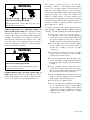
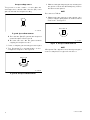
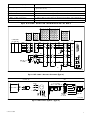
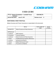
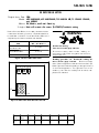
SB-555 5/96
SERVICE BULLETIN
Original Issue Date: 5/96
Model: 4/5CKM/CKMR, 4CFKM/CFKMR, 7CCKM/CCKMR, 7CCFKM/CCFKMR,
and 6.5RMY
Market: RV, Mobile, and Small Standby
Subject: Kohler Electronic Governor (D-278670) Troubleshooting
WARNING
Kohler Generator Division, in an attempt to reduce returns
of functional electronic governors, created this bulletin to
better inform customers. Consult the Service Manual for
adjustment procedures not found in this bulletin.
Service Manual
Publication Number
Model
4/5CKM/CKMR
4CFKM/CFKMR
7CCKM/CCKMR
7CCFKM/CCFKMR
6.5RMY
TP-5394
TP-5570
TP-5632
Figure 1. Service Manual Selection
P7
M4
Disabling generator set. Accidental starting can
cause severe injury or death. Disconnect battery
M2
70
M1
AD
MP
MP
Disconnect battery cables before working on
generator set (disconnect negative lead first and
reconnect it last).
cables (remove negative lead first and reconnect it last) to
disable generator set before working on the generator set
or connected equipment. The generator set can be
started by the remote start/stop switch unless this
precaution is followed.
OVER
SPEED GAIN SPEED
M3
Accidental starting.
Can cause severe injury or death.
N
P2
Figure 2. Kohler Electronic Governor Control
Routing
Initial
Here
Service
Manager
Sales
Manager
Parts
Manager
Technician
No. 1
Technician
No. 2
Technician
No. 3
Return
This to
WARNING
Hazardous voltage.
Moving rotor.
Can cause severe injury or death.
Operate generator set only with all guards and
electrical enclosures in place.
Grounding generator set. Hazardous voltage can
cause severe injury or death. Electrocution is possible
whenever electricity is present. Open main circuit
breakers of all power sources before servicing equipment.
Configure the installation to electrically ground the
generator set and electrical circuits when in use. Never
contact electrical leads or appliances when standing in
water or on wet ground, as the chance of electrocution is
increased under such conditions.
WARNING
Rotating parts.
Can cause severe injury or death.
Do not operate generator set without all guards,
screens, and covers in place.
Exposed moving parts can cause severe injury or
death. Keep hands, feet, hair, and clothing away from
belts and pulleys when unit is running. Replace guards,
covers, and screens before operating generator set.
2
The governor system consists of an electronic
isochronous governor, an electro-mechanical stepper
motor, and a magnetic pickup. Electrical pulses are
supplied by the magnetic pickup to the isochronous
governor (control unit) each time one of the ring gear teeth
passes the pickup. The control unit compares the
frequency of these pulses to a preset reference and
provides a signal to the stepper motor which controls the
carburetor throttle position and the engine speed. This is a
closed-loop system and typically provides steady-state
speed regulation of 0.25%.
The factory sets the electronic governor and the governor
usually requires no further adjustment. If the unit operates
erratically, check the following items before readjustment.
D Check the carburetor for dirt, grime, or
misadjustment. Also, check the idle-adjustment
screw. The screw should not prevent the throttle
plate from completely closing. Also, check the
throttle linkage for any binding, dirt, damage, etc.
D Check electrical connections— check the stepper
motor, controller box, and governor connector
(inside the controller) for clean and tight
connections.
D Check electrical ground connections— a good DC
ground must be provided to the controller
assembly and governor circuit.
D Check for a good positive 12-volt DC supply. Also
check if the positive voltage supply is unstable or
below 8-volts DC making the control unit function
erratically.
D Check magnetic pickup connections. Poor
connections may cause the signal to be erratic.
As long as this erratic signal is being sent, the unit
will not shut down due to loss of pickup.
D Check for dirt buildup on magnetic pickup— metal
filings or caked-on dirt/grease may decrease the
output signal of the magnetic pickup.
D Check for a loose coupling screw.
D Check for stepper motor/throttle shaft coupling
wear— if the roll pin wore the slot of the stepper
motor coupling, loosen coupling screw and move
coupling so that roll pin is positioned at a point in
stepper motor coupling without wear. Tighten
coupling screw.
SB-555 5/96
Magnetic Pickup
(See Figure 3 or Figure 4)
The magnetic pickup provides an AC signal to the control
unit. Minimum voltage output from the pickup during
engine cranking should be 1.75 VAC.
4
Air Gap
(See Figure 3 or Figure 4)
The air gap between the ring gear and pickup should be
0.040 inches.
NOTE
Measure the air gap at 3 or 4 places to get an accurate
reading.
To adjust air gap, loosen the locknut and turn pickup
bottoms on the ring gear, then back
clockwise until it
out 3/4 turns.
Hold pickup in this position while retightening locknut.
If loss of signal or failure of the pickup occurs while
running, the governor control will de-energize the
carburetor shut-off solenoid to stop the engine.
2
1
3
just
TP-5572-6
1.
2.
3.
4.
0.04-in. air gap
Top of flywheel ring gear tooth
Magnetic pickup generates an AC voltage
Locknut
Figure 3. Magnetic Pickup Air Gap
(4/5CKM/CKMR and 6.5RMY)
1
2
TP-5572-6
1. Ignition coil
2. Magnetic pickup
Figure 4. Magnetic Pickup (7CCKM/CCKMR)
SB-555 5/96
3
Actuator
(See Figure 5 and Figure 6)
The actuator consists of a stepper motor coupled to the
carburetor throttle shaft.
It receives signals from the governor control unit and
rotates the shaft to the proper position.
To test for proper operation of the actuator, disconnect
magnetic pickup leads. Manually move the throttle
shaft/governor stepper motor fully counterclockwise
(closed throttle). Start generator set. Actuator should
initially move clockwise (wide-open throttle) and then turn
completely counterclockwise. The actuator should
remain in this position. Stop generator set. If actuator fails
this test, replace actuator.
The governor actuator should function with steady and
smooth movement during operation. If movement of
actuator is erratic or large changes in movement occur:
D Check shaft alignment— ensure that the actuator
and throttle shafts are concentric and that the
throttle-shaft pin is at midpoint of the actuator slot
D Check for excessive coupling slot wear— replace
worn parts
D Check for broken or loose wiring including plug
connections
Adjust coupling so throttle shaft pin is recessed to the
middle of the slot.
Stepper-motor rotational position adjustment is not
necessary. Throttle plate position can be either open or
closed during assembly.
Only two actuator leads of each coil group are utilized.
(BLK-YEL, and RED-WHT.) Resistance per phase: 38.5
ohms.
Voltage pulses received from the governor control
determine movement of the stepper motor.
NOTE
A 12-VDC voltage applied to the motor leads will result in a
single-step movement of 1.8_. Reversal of the voltage
polarity will result in a 1.8_ movement in the reverse
direction.
TOP VIEW
2
1
3
5
4
1
6
7
4
1.
2.
3.
4.
5.
6.
7.
TP-5572-6
Actuator
Coupling
Closed throttle
Intake air flow
Pin
Set screw
Open throttle
Figure 5. Actuator (Stepper Motor)
BLK
YEL
GRN
RED WHT BLU
TP-5572-6
Figure 6. Actuator Coil Group
NOTE
The stepper motor will not continuously rotate with battery
voltage supplied to its windings.
4
SB-555 5/96
Governor Control
The electronic control board provides power to the
actuator. It also controls energizing and de-energizing of
the fuel— anti-diesel (AD) solenoid or gas valve.
Prior to any governor adjustments:
1. Open the line circuit breaker between the generator
and any loads which may be frequency sensitive.
2. Connect a frequency meter to the generator AC
output in order to monitor AC output while making
adjustments.
Gain Adjustment
The Gain Potentiometer (Pot) pertains to governor
sensitivity. See Figure 8.
GAIN
Speed Adjustment
Turn speed potentiometer clockwise to increase speed,
counterclockwise to decrease speed. See Figure 7.
TP-5572-6
Figure 8. Gain Potentiometer
D
OVER
SPEED GAIN SPEED
D
D
Move Gain Pot in 1/8-turn increments if hunting or
surging occurs.
Changing the Gain Pot setting may affect the
governor Speed Pot.
Governor Speed Pot adjustment will not affect
the Gain Pot.
4-Pole Generators
60 Hz = 1800 RPM
50 Hz = 1500 RPM
TP-5572-6
Figure 7. Speed Potentiometer
SB-555 5/96
5
Overspeed Adjustment
The governor control contains a circuit which will
de-energize the carburetor fuel solenoid (AD) if the
generator exceeds the overspeed setting.
3. While observing the frequency meter, manually turn
the governor actuator shaft until frequency reaches
the desired cut-out speed.
Do not exceed 72 Hertz
NOTE
4. While keeping the generator at the desired cut-in
speed, slowly turn Overspeed Pot clockwise until unit
shuts down. See Figure 11.
SPEED
TP-5572-6
OVERSPEED
Figure 9. Speed Potentiometer
Do not use the Speed Pot to check the overspeed
shutdown setpoint. See Figure 9.
D Disconnect all loads from the generator when
adjusting the overspeed cutout.
1. Connect a frequency meter to the generator output.
2. Turn Overspeed Pot counterclockwise to max.
overspeed cut-out point. See Figure 10.
D
TP-5572-6
Figure 11. Overspeed Potentiometer
NOTE
If Overspeed Pot is adjusted too low, the engine may shut
down on startup because of governor overshoot.
OVERSPEED
TP-5572-6
Figure 10. Overspeed Potentiometer
6
SB-555 5/96
Result
Condition (Fault)
Throttle moves to closed position and fuel shut-off solenoid de-energizes
(genset shutdown)
Fuel shut-off solenoid de-energizes (genset shutdown)
Fuel shut-off solenoid de-energizes
Fuel shut-off solenoid de-energizes (genset shutdown)
Erratic performance then fuel shut-off solenoid de-energizes (genset shutdown)
Erratic performance then fuel shut-off solenoid de-energizes (genset shutdown)
Loss of pickup while running
Engine overspeed
Break of fuel shut-off solenoid lead
Loss of DC power to governor assembly
Break of stepper motor leads
Actuator linkage failure
Figure 12. Electronic Governor Fault Shutdown Conditions and Results
1
2
GOVERNOR
ACTUATOR
WHT.
YEL.
BLK.
RED
GRN.
BLU.
1
1
2
3
4
5
6
7
8
2
9
10 11 12
4
3
3
4
13 14 15 16
6
5
5
6
17 18 19 20
P9
J9
1
2
3
4
5
6
1
2
3
4
5
6
M2
M4
M3
M1
P4
16
17
9
10
4
3
2
1
7
6
5
3
2
1
12 11
8
10
9
6
5
4
16 15 14 13
9
8
7
20 19 18 17
12 11 10
J4
P7
J7
16
17
9
10
M2
M4
M3
M1
1
2
3
4
N
10
1
2
3
4
10
MP
MP
11
13
11
13
MP
MP
11
7
11
7
AD
70
1
1
AD
9
6
9
6
CARB.
MAGNETIC
PICKUP
AD
B+
70
TP-5572-6
Figure 13. Electronic Governor Schematic (Typical)
Schematic
GOVERNOR
MP
MP
MP
Line
BLACK
YEL
GREEN
ELECTRONIC
GOVERNOR BOARD
STM
P6--5
P6--6
OVER GAIN SPEED
SPEED
MAGNETIC
PICKUP
SENSOR
Figure 14. Schematic Symbols (Typical)
SB-555 5/96
YELLOW
WHITE
BLACK
GREEN
RED
BLUE
STEPPER
MOTOR
TP-5572-6
7