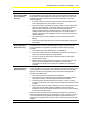
1
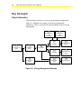
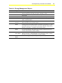
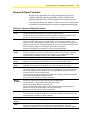
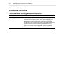
N30 Supervisory Controller User’s Manual
A-1
Appendix A
Building an Energy Management
Application
Introduction
Numerous energy management applications are possible for small to
mid-size site configurations. This document provides information to
consider when building a core energy management application,
including what objects are involved and how attributes interact.
This document describes how to build a core energy management
application.
© November 01, 2001 Johnson Controls, Inc.
Code No. LIT-6892310
www.johnsoncontrols.com
Software Release 5.0
A-2
N30 Supervisory Controller User’s Manual
Key Concepts
Object Interaction
Different objects interact in a core energy management application.
Figure A-1 illustrates an example of an energy management
application. Table A-1 describes the objects and their role in energy
management.
7
8
N2 Binary Input
Object
(Output Alarm)
N2 Binary Input
Object
(Comfort Alarm)
2
6
Load Object
N2 Binary Output
Object
2
6
Load Object
N2 Binary Output
Object
4
3
9
Pulse Meter
Object
Utility Profile
Object
Schedule Object
5
4
1
N2 Pulse Counter
Object
Pulse Meter
Object
DLLR Object
DLLR Flow
Figure A-1: Energy Management Example
N30 Supervisory Controller User’s Manual
A-3
Table A-1: Energy Management Objects
Number
Object
Role
1
DLLR
Receives energy consumption data from the Pulse Meter object to manage
demand limiting and load rolling through the shedding of loads.
2
Load
Registers with the DLLR object to let the DLLR object know that it exists and
can be shed.
3
Utility Profile
Collects utility data from a Pulse Meter object and a DLLR object.
4
Pulse Meter
Collects energy consumption data to be available to either the Utility Profile
object or the DLLR object.
5
N2 Pulse
Counter
Counts energy pulses via the N2 Bus from an actual hardware meter and
relates the data to the Pulse Meter object.
6
Output
Object
Acts as the associated output for the Load object, which switches it off for the
actual physical load shedding. Besides an N2 Binary Output object, a Load’s
associated output can also be a Binary Value (BV), Multistate Output (MSO),
Multistate Value (MSV), or Multiple Command (MC) object.
7
Output Alarm
Object
Provides the attribute supplying the output alarm condition. This attribute can be
any numerical attribute of any object type in which a change from zero to a
non-zero value indicates an alarm condition.
8
Comfort
Alarm Object
Provides the attribute supplying the comfort override alarm condition. This
attribute can be any numerical attribute of any object type in which a change
from zero to a non-zero value indicates an alarm condition.
9
Schedule
Object
Starts new billing periods by resetting the Utility Profile object.
A-4
N30 Supervisory Controller User’s Manual
Attribute Involvement
Building a core energy management application means that each
object must have its attributes configured to reference the appropriate
objects in order to achieve the desired results. Table A-2 lists the
objects and attributes involved and guidelines for data entry.
Table A-2: Key Components for a Core Energy Management Application
Object
Type/Function
Attributes
Involved
Data Entry Guidelines
DLLR
Meter Object
Enter the exact name of that Pulse Meter object, which is
dedicated to serve only as an input to this particular DLLR object.
Load
DLLR Object
Enter the exact name of the DLLR object.
Output Attribute
Enter the attribute of the output object that will be shut off to shed
the load. Make sure that the attribute supports a prioritized write.
Output Alarm Attr
Enter the attribute supplying the Output Alarm condition.
Comfort Alarm Attr
Enter the attribute supplying the Comfort Alarm condition.
Meter Object
Enter the exact name of that Pulse Meter object, which is
dedicated to serve only as an input to this particular Utility Profile
object.
DLLR Object
Enter the exact name of the DLLR object.
Pulse Meter
Counter Object
Enter the exact name of the N2 Pulse Counter object. The
N2 Pulse Counter object must reside on the same device as the
Pulse Meter object.
N2 Pulse Counter
None
None. The Pulse Meter object references this object.
Output Object
None
None. The Load object references this object’s Output Attribute.
Output Alarm
Object
None
None. The Load object references this object ‘s Output Alarm
attribute.
Comfort Alarm
Object
None
None. The Load object references this object’s Comfort Alarm
attribute.
Schedule Object
List of Prop Refs
Enter the name of the Utility Profile object and schedule the
Utility Profile’s Reset attribute to go to 1 at the time you want a
new billing period to start, and to go back to 0 one minute later.
Setting back the reset attribute is necessary to avoid a premature
start of the billing period in case the Schedule’s fast clock feature
should run.
Utility Profile
N30 Supervisory Controller User’s Manual
A-5
Advanced Object Functions
Beyond a core application, the energy management objects can
combine with other objects to perform a variety of functions for
sophisticated applications. The possibilities are too numerous to be
covered in this document. Table A-3 offers an overview of the objects
and advanced functions possible in energy management applications.
Table A-3: Advanced Object Functions
Object
Function
DLLR
Operates at different demand limits and load rolling targets over time.
Allows an external source instead of the internal algorithm to dictate the amounts to shed.
Accounts for Pulse Meter failure through the configuration of its algorithm.
Load
Adapts shedding priority to the current situation.
Performs local load rolling, such as cyclically running one out of many air handlers. This
requires the load to drive a Multiple Command object, which coordinates the local load rolling.
Handles analog loads, such as adjusting setpoints when shed. Again, this functionality is best
achieved through a Multiple Command object as the load’s output object.
Remains shed through load configuration in case of an abnormal situation.
Utility
Profile
Provides a breakdown of energy consumption data over variable time periods.
Provides a breakdown of energy consumption data into different energy tariffs. In this case
one Utility Profile per tariff must be used. The coordination of the Utility Profiles is best
achieved through scheduling, interlock, and/or multiple command objects.
Pulse Meter
Allows electronic filtering of the pulse rate input signal by varying its Sample Time attribute.
Analog
Alarm
Provides detailed alarm notification for any abnormal situations in the energy management
application. Alarm objects can be attached to any numerical attribute of any object.
Multistate
Alarm
Provides detailed alarm notification for any abnormal situations in the energy management
application. Alarm objects can be attached to any numerical attribute of any object.
Interlock
Monitors any numerical attribute of any object involved in the DLLR application.
Invokes any command of any object involved in the DLLR application. Can send commands
with or without delays to itself. This opens up many opportunities for periodic execution of
certain processes, such as local load rolling.
Tunes the energy management application at runtime by modifying parameters in the DLLR
and Load objects depending on certain conditions.
Serves as Comfort Alarm points used by Load objects.
Multiple
Command
Invokes any command of any object involved in the DLLR application.
Coordinates which of several Utility Profiles currently is active.
Replaces an N2 Binary Output as a load’s output.
Sends commands with or without delays to itself. This opens up many opportunities for
periodic execution of certain processes, such as local load rolling.
Serves as Comfort Alarm points used by Load objects.
Schedule
Resets Utility Profiles or to select the currently active Utility Profile.
Tunes the energy management application at runtime by modifying parameters in the DLLR
and Load objects, depending on certain conditions.
Trend Log
Provides additional detailed energy data.
Global Data
Sharing
Propagates data within the energy management application.
Signal
Select
Changes attributes of the objects.
Monitors numerical attributes and subsequently propagates data within the energy
management application, based on the result of the logic evaluation of the input conditions.
A-6
N30 Supervisory Controller User’s Manual
Procedure Overview
Table A-4: Building an Energy Management Application
To Do This
Follow These Steps:
Build an Energy Management
Application
Add N2 point objects to the database, including N2 Pulse Counter objects.
Add the DLLR object. Add a Pulse Meter object referencing the N2 Pulse
Counter object and the DLLR object. Add a Utility Profile object to the
same device as the Pulse Meter and DLLR objects. Add another Pulse
Meter object referencing the N2 Pulse Counter object and the Utility
Profile object. Add Load objects referencing output loads to potentially be
shed and referencing objects representing an Output Alarm and a
Comfort Alarm. Add a Schedule object referencing the Utility Profile
object. Verify that the energy management application is operating
correctly.
N30 Supervisory Controller User’s Manual
A-7
Detailed Procedures
Building an Energy Management Application
To build an energy management application:
1.
Add N2 point objects to the database, including N2 Pulse Counter
objects. See the N30 Supervisory Controller Point Mapping
Technical Bulletin (LIT-6891400).
2.
Add the DLLR object. One DLLR object exists per meter
hardware piece. For example, a building with three electric meters
should have three DLLR objects to regulate the system. Multiple
DLLR objects can exist in one N30.
3.
Add a Pulse Meter object referencing the N2 Pulse Counter object
and the DLLR object. The Pulse Meter should be on the same
device as the DLLR object.
4.
Add a Utility Profile object to the same device as the Pulse Meter
and DLLR objects.
5.
Add another Pulse Meter object referencing the N2 Pulse Counter
object and the Utility Profile object. One Pulse Meter object
should be dedicated to one Utility Profile object.
6.
Add Load objects referencing output loads to potentially be shed
and referencing objects representing an Output Alarm and a
Comfort Alarm. A maximum of 80 Load objects can register to
one DLLR. A maximum of 80 output objects can be referenced by
the 80 Load objects.
7.
Add a Schedule object referencing the Utility Profile object. This
Schedule is required to reset the Utility Profile object at the end of
each billing period. Enter the name of the Utility Profile object
and schedule the Utility Profile’s Reset attribute to go to 1 at the
time you want a new billing period to start, and to go back to 0
one minute later. Setting back the reset attribute is necessary to
avoid a premature start of the billing period if the Schedule’s fast
clock feature should run.
8.
Verify that the energy management application is operating
correctly. Refer to the Troubleshooting section of this document.
A-8
N30 Supervisory Controller User’s Manual
Troubleshooting
This section provides some guidelines for making an energy
management application successful.
Table A-5: Energy Management Troubleshooting Guidelines
Guideline
Procedure
Ensure All Loads are
Capable of
Registering Correctly
It is best to throttle (regulate the speed of) the load registration process by
modifying each Load object’s Registering Delay attribute, if one or more of the
following conditions exist:
•
twenty or more Load objects are used per DLLR object
•
Load objects are mainly not on the same device as the DLLR object
•
the device housing the DLLR object is likely to be low on acquired memory
To throttle the load registration process, assign a Register Delay of 5 seconds to
the first load to register, a delay of 6 seconds to the next, and so on. This results in
approximately one incoming registration message per second during the
Registering Phase. This also results and in a predictable order for the list of loads
kept inside the DLLR object.
Leaving the Register Delay attributes of all Load objects to zero seconds result in
the fastest possible load registration. However, if this overloads the device, such as
an N30, housing the DLLR object, use the Register Delay attributes to throttle the
registration process.
Ensure All Loads are
Registered Correctly
After creating the entire database, check if the Load objects are correctly
registered at their respective DLLR objects. Depending on the configuration
settings in the Load or DLLR objects, some loads may not have registered. Also,
creating the database while certain devices are offline may result in unregistered
loads.
1. Check if the DLLR object’s Number of Loads attribute matches the number of
loads expected to be registered (the number of loads created to register to the
DLLR object). If the numbers match, the loads are registered correctly. If not,
go the Step 2.
2. If the numbers do not match, or to ensure the correctness of the load
registration process, run the DLLR object’s Force Register command:
•
•
To get all loads to register while the DLLR algorithm is not yet in a stage
in which it would be harmful to suspend its operation, run the DLLR
object’s Force Register command with the command parameter set to
True. This command erases the entire load registration information inside
the DLLR object, and starts a new registration process.
To get all loads to register while the DLLR algorithm is already in a stage
in which it is critical not to suspend its operation, run the DLLR object’s
Force Register command with the command parameter set to False.
This command preserves the entire load registration information inside the
DLLR object while starting a new registration process.
3. Wait the amount of time equal to the Register Delay attribute, and then
recheck if the DLLR object’s Number of Loads attribute now matches the
number of loads expected to be registered.
Note:
Since the Number of Loads attribute does not refresh automatically,
refresh the display by closing the current view and reopening it.
Continued on next page . . .
N30 Supervisory Controller User’s Manual
A-9
Guideline (Cont.)
Procedure
Ensure All Loads are
Registered Correctly
(Cont.)
4.
Ensure All Loads are
Potentially Eligible for
Shedding
An incorrectly configured load may never be eligible for shedding and therefore be
of no use to the system.
To check if all loads have the potential to be eligible, each load must be individually
checked.
1. Check if the DLLR object’s Eligible for DL Only, Eligible for LR Only, and
Eligible for DLLR attributes add up to the Number of Loads attribute. If the
numbers add up, and the DLLR object’s Not Eligible attribute is zero, the loads
are eligible for shedding. If both conditions are not met, continue with Step 2.
Note:
The above attributes do not refresh automatically each time they are
updated. To refresh the display, close the current view and reopen it.
2. Check each Load object’s Eligibility attribute. If Ineligible, continue with Step 3.
3. Check each Load object’s Shed Refusal attribute for a reason why the Load
may be ineligible for shedding.
4. Remove all of the conditions listed in the Load object’s Shed Refusal attribute
until the load becomes eligible, and Shed Refusal becomes No Refusal.
If the numbers still do not match, and re-sending the Load object’s Force
Register command does not correct the situation, check each Load object’s
Load Number attribute. A load number of zero indicates unsuccessful
registering that can be the result of several factors. Each Load object with a
Load Number attribute value of zero should be checked with these steps:
a. Check if all Load objects are online to their DLLR object. If all are online,
the loads are registered correctly. If not, continue with Step 4b.
b. Check if all Load objects have the correct name of the DLLR object
entered in their DLLR object attribute. If all have the correct name, all
loads are registered correctly. If not, continue with Step 4c.
c. Run the Force Register command for each questionable load.
d. Wait until the Registering Delay time has elapsed, then recheck the Load
Number attribute to see if it contains a non-zero number. This would
indicate that the load is now registered. In addition, if the DLLR object’s
Number of Loads attribute increases by one, this also indicates the load is
now registered.
e. Repeat Steps 4c and 4d. If it still appears that loads are not registered,
continue with Step 4f.
f. Check the DLLR object’s Registering Phase attribute. This attribute
defines the length of the registration process. In large systems it may be
necessary to extend this value to a time similar to the highest Register
Delay attribute.
g. Run the DLLR object’s Force Register command with the command
parameter set to True. This assures that loads are registered correctly, as
long as they are configured correctly and online.
If running the DLLR object’s Force Register command never results in correct load
registration, a memory or communication overload may exist, and registration
messages may be lost. In this case, throttle the registration process as described
earlier. If this does not improve the registration process, there may be a
communication or memory problem in the system, requiring a re-evaluation of the
entire system.
Continued on next page . . .
A-10
N30 Supervisory Controller User’s Manual
Guideline (Cont.)
Procedure
Ensure the Pulse
Meter is Working
Correctly
If you want to use the Demand Limiting feature of the DLLR object, a rate of
consumption must be fed into the algorithm. While this rate could be provided by
any analog Present Value attribute of type float, the DLLR object is optimized to
use a Pulse Meter object as its input.
To ensure proper Pulse Meter operation:
1. Check the Pulse Meter object’s Reliability attribute. If it is Reliable, the Pulse
Meter object is operating correctly. If the value is Unreliable for more than a
few minutes, the Pulse Meter object is not working correctly. Go to Step 2.
2. Check if the Pulse Counter object specified in the Pulse Meter’s Counter
Object attribute resides on the same device as the Pulse Meter. If both objects
reside on the same device, but the Pulse Meter object is still Unreliable, go to
Step 3.
3. Verify that the Pulse Counter object’s N2 device is online.
4. Check if the value of the Pulse Meter object’s Consumption attribute actually
represents the consumption of a single pulse. Refer to the meter’s type plate
or user manual.
5. Check if the value of the Pulse Meter object’s Rate Constant attribute equals
the Rate Units attribute multiplied by seconds divided by the value of the
Consumption Units attribute. For example, if the Rate Unit is KW, and the
Consumption Unit is KWh, the correct value of the Rate Constant attribute
must be KWs / KWh = 3600 s/h.
6. Check that the calculated rate does not exceed the Pulse Meter object’s Rate
Limit attribute. To estimate the calculated rate:
a. Monitor the Pulse Meter’s Pulse Count attribute for a minute. It should
increase by a few points within that minute. However, in some cases the
rate of consumption is so low that no pulse is generated in a minute. If this
is true, wait until a pulse is generated and counted by the Pulse Counter
object and keep track of the time until the next pulse.
b. Multiply the number of Pulse Counts from Step 6a with the value of the
Pulse Consumption attribute, then divide it by the pulse counting period
length in seconds, and multiply that result by the value of the Rate
Constant attribute. The result should be reasonable. In most cases, you
can refer to figures from utility bills to check if the values are reasonable.
c. Make sure the Pulse Meter object’s Sample Time is set to 60 seconds.
This ensures that the DLLR algorithm always uses current data calculated
from the last minute’s consumption.
If a Sample Time of 60 seconds provides too few pulses to reasonably
operate the Demand Limiting algorithm, use a different pulse generator
with a higher resolution. The pulse count is too low if 60-second intervals
without any pulses occur, even during normal building operation.
However, sampling no pulses during some minutes at night may be a
reasonable rate. The DLLR algorithm works best when the rate is higher
than ten pulses per minute. This way the rate used in the algorithm is at
least within 10% of its real value.
When a meter different from a Pulse Meter is used, most considerations described
above do not apply. In this case, make sure the meter’s Present Value attribute
can be correctly read, and that it represents the average demand during the last
60 seconds.
Continued on next page . . .
N30 Supervisory Controller User’s Manual
A-11
Guideline (Cont.)
Procedure
Ensure the
End-of-Interval (EOI)
Pulse is Working
Correctly
When the Fixed Window Algorithm is used, the End-of-Interval information has to
be made available to the DLLR object. After one entire interval has elapsed, the
DLLR object’s EOI Alarm attribute should remain set to False. If it is set to True,
the DLLR object did not receive the End-of-Interval information. In this case,
check the following:
1. If the utility company provides the End-of-Interval pulse, verity that the EOI
pulse creating device is correctly wired to the system.
2. Verify that the object, typically a BI, actually changes to True for a short time
when the pulse is detected. The pulse should be long enough to allow the
N2 Bus to poll the high value from the N2 controller and generate a
Change-of-Value message to the DLLR object. In case the pulse cannot be
reliably transferred into a BI or similar object and on to the DLLR object, a
latching mechanism has to be added that ensures a pulse long enough to be
definitely detected.
3. Verify that the End-of-Interval regularly occurs once after each interval is
finished.
4. Verify that the object providing the End-of-Interval information is online to the
DLLR object.
Ensure the Load
Rolling Algorithm is
Working Correctly
The DLLR object’s Load Rolling algorithm, when the LR Mode attribute is set to
LR Shedding, tries to keep the LR Shed attribute equal to or greater than the
LR Target attribute. This algorithm can easily be verified using the following
procedure:
1. Set the DLLR object’s LR Mode attribute to LR Shedding.
2. Verify that the DLLR object’s LR Shed attribute quickly becomes equal to or
greater than the DLLR object’s LR Target attribute.
3. If it does not reach the target, verify that the DLLR object’s DLLR Status
attribute reads In Alarm.
4. Make sure that the DLLR object’s LR Target is not unreasonably high, and
ensure that enough eligible loads are available to meet the target.
Occasionally not meeting the LR Target is acceptable, but it should be an
exception.
Ensure the Demand
Limiting Algorithm is
Working Correctly
When the DLLR object’s DL Mode attribute is set to Shedding, the Demand
Limiting algorithm tries to keep the Interval Demand below the Demand Limit. The
correct operation of the algorithm is much harder to verify than the Load Rolling
algorithm. Use this general guideline to see if the Demand Limiting algorithm
produces reasonable results:
1. Set the DLLR object’s DL Mode attribute to Shedding.
2. Verify that the value of the DLLR object’s Interval Demand attribute always
stays below the value of the DLLR object’s Demand Limit attribute.
3. If Interval Demand exceeds the Demand Limit value, or when it is close to
exceeding the Demand Limit, verify that the DLLR object’s DLLR Status reads
In Alarm.
4. Make sure that the DLLR object’s Demand Limit is not unreasonably low, and
ensure that enough eligible loads are available to avoid exceeding the
Demand Limit. Do not exceed the Demand Limit, since it may cause penalties
to be paid to the utility company.
If there are severe consequences for exceeding the Demand Limit, start with a
much lower Demand Limit during the first weeks or months of operation to ensure
not to exceed the limit. With growing knowledge of the system’s behavior, the
Demand Limit may gradually be set closer to the actual limit provided by the utility
company.
Continued on next page . . .
A-12
N30 Supervisory Controller User’s Manual
Guideline (Cont.)
Procedure
Ensure the Demand
Limiting Load Rolling
Object is Working
Correctly
The DLLR object’s DLLR Status attribute summarizes the overall state of the DLLR
object. The value should be Normal except when it is in its registering phase.
Please verify the following additional DLLR attributes for more detailed information
about how the DLLR application is behaving:
•
Reliability
•
DLLR Alarm Reason
•
Meter Alarm
•
EOI Alarm
•
Meter Value
The following attributes also provide more detailed information about how the
DLLR application is doing. In some cases it takes expertise to interpret the results,
but severe errors or malfunctions should be easily identifiable.
•
Number of Loads Eligible For DLLR
•
Eligible For DL Only
•
Eligible For LR Only
•
Not Eligible
•
Highest Load Shed Sent
•
Shed Accepted
•
Shed Refused
•
Shed Pending
•
Shed Lost
•
Shed Not Sent
•
Interval Demand
•
Unc Interval Demand
•
Demand History
•
Unc Demand History
•
Amount Shed
•
LR Shed
•
LR to Shed
•
LR not Shed
•
DL Shed
•
DL to Shed
•
DL not Shed
Fixed Window Algorithm Only
•
Calculation Active Limit
•
Active Elevation
•
Time Until EOI
•
Time Since EOI
•
Energy Since EOI
•
Demand Since EOI
•
Profile Limit
•
Max Demand
Continued on next page . . .
N30 Supervisory Controller User’s Manual
A-13
Guideline (Cont.)
Procedure
Ensure the Utility
Profile Application is
Working Correctly
The modular design of the Utility Profile makes it possible to track consumption
data and peak data broken down into a variety of specific tracking periods, such as
tracking periods for specific utility tariffs, days, weeks, months, or for any other
reason you may want to create separate tracking records.
The Utility Profile object should ideally reside either close to the Pulse Meter object
or the DLLR object. Ideally Pulse Meter and DLLR objects should reside in the
same device.
To verify the correct operation of the Utility Profile application:
1. Check the Utility Profile object’s Meter Active attribute. It should be either
Normal if the object is currently tracking data, or it should be Suspended if it is
currently not tracking data.
2. Make sure each Utility Profile object has a dedicated Pulse Meter object. The
Meter Active attribute of the Pulse Meter object must always be identical to the
Meter Active attribute of the Utility Profile object.
3. Check if the Pulse Meter object specified in the Utility Profile’s Meter object
attribute is an online Pulse Meter object.
4. Check if any Peak Unreliable or Consump Unreliable flags are set for each
Utility Profile object. Also check the Historical Data attribute for these flags. If
both the Pulse Meter and the DLLR object continuously provided reliable data,
there should be no indication of unreliable data in the Utility Profile object.
However, some previous conditions may have left their unreliability mark in the
utility profile data.
After each Utility Profile object has begun collecting, check for reasonable data for
the following attributes:
•
Period Start Date
•
Period Start Time
•
Consumption Unc
•
Consump Unreliable
•
Peak Unreliable
•
Demand Peak
•
Demand Peak Date
•
Demand Peak Time
•
Unc Demand Peak Date
•
Unc Demand Peak Time
•
Historical Data
Figures from previous utility bills as well as some common sense should be
enough to determine if the results are reasonable.
Ensure the DLLR
Energy Management
Application is
Working Correctly
Run the following test to verify the system is configured correctly. Certain tests may
require modification of values to simulate conditions that would not occur under
normal operations.
1. Verify all alarm messages generated by DLLR related objects are correctly
delivered to all their destinations. Invoking alarm messages may require
temporary manipulation of DLLR related data.
2. Verify all schedules involved in the DLLR application schedule the correct
objects at the correct times.
3. Verify all calendars are correctly tied into the DLLR application.
4. Verify there are no unbound references in the entire DLLR application. The
unbound references can be found in the Unbound References attribute of
each device object involved in the DLLR application.
5. Verify each device has sufficient memory and processor bandwidth. Refer to
the device object’s user manual for more information on how to verify these
conditions.