1
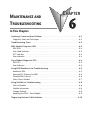
MAINTENANCE AND
TROUBLESHOOTING
In This Chapter:
CHAPTER
6
Isolating a Communication Problem . . . . . . . . . . . . . . . . . . . . . . . . . . . . . . . . . . . .6–2
Diagnostic Tools and Techniques . . . . . . . . . . . . . . . . . . . . . . . . . . . . . . . . . . . . . . .6–2
Troubleshooting Chart . . . . . . . . . . . . . . . . . . . . . . . . . . . . . . . . . . . . . . . . . . . . . . .6–2
ERM Module Diagnostic LEDs . . . . . . . . . . . . . . . . . . . . . . . . . . . . . . . . . . . . . . . . .6–4
ERM LEDs . . . . . . . . . . . . . . . . . . . . . . . . . . . . . . . . . . . . . . . . . . . . . . . . . . . . . . . .6–4
Link Good Indicator . . . . . . . . . . . . . . . . . . . . . . . . . . . . . . . . . . . . . . . . . . . . . . . . .6–4
ACT Indicator . . . . . . . . . . . . . . . . . . . . . . . . . . . . . . . . . . . . . . . . . . . . . . . . . . . . .6–4
Error Indicator . . . . . . . . . . . . . . . . . . . . . . . . . . . . . . . . . . . . . . . . . . . . . . . . . . . . .6–4
Slave Module Diagnostic LEDs . . . . . . . . . . . . . . . . . . . . . . . . . . . . . . . . . . . . . . . . .6–4
EBC LEDs . . . . . . . . . . . . . . . . . . . . . . . . . . . . . . . . . . . . . . . . . . . . . . . . . . . . . . . . .6–4
Error Indicator . . . . . . . . . . . . . . . . . . . . . . . . . . . . . . . . . . . . . . . . . . . . . . . . . . . . .6–4
Using ERM Workbench for Troubleshooting . . . . . . . . . . . . . . . . . . . . . . . . . . . . . .6–5
Read from ERM . . . . . . . . . . . . . . . . . . . . . . . . . . . . . . . . . . . . . . . . . . . . . . . . . . . .6–5
Reserved PLC Memory for ERM . . . . . . . . . . . . . . . . . . . . . . . . . . . . . . . . . . . . . . . .6–6
Detailed ERM Statistics . . . . . . . . . . . . . . . . . . . . . . . . . . . . . . . . . . . . . . . . . . . . . . .6–6
Select Slaves Window . . . . . . . . . . . . . . . . . . . . . . . . . . . . . . . . . . . . . . . . . . . . . . .6–7
Using NetEdit for Troubleshooting . . . . . . . . . . . . . . . . . . . . . . . . . . . . . . . . . . . . .6–8
Select a Module . . . . . . . . . . . . . . . . . . . . . . . . . . . . . . . . . . . . . . . . . . . . . . . . . . . .6–8
Module Information . . . . . . . . . . . . . . . . . . . . . . . . . . . . . . . . . . . . . . . . . . . . . . . . .6–8
Change Protocol . . . . . . . . . . . . . . . . . . . . . . . . . . . . . . . . . . . . . . . . . . . . . . . . . . .6–9
Replacing the ERM / Slave Module . . . . . . . . . . . . . . . . . . . . . . . . . . . . . . . . . . . . .6–9
Diagnosing Network Cable Problems . . . . . . . . . . . . . . . . . . . . . . . . . . . . . . . . . .6–10
Chapter 6: Maintenance and Troubleshooting
Isolating a Communication Problem
If you are experiencing a problem communicating with an ERM module or one of its
1
slaves, the problem can usually be isolated to one of four components of the
2
communication link:
•the Ethernet module itself (hardware or firmware)
3
•the setup of the ethernet module
•the cabling or connections
4
•other external influences, such as electrical noise, heavy communication traffic on the network or
exceeding the power budget
5
Diagnostic Tools and Techniques
Several available tools and techniques can help you isolate a communication
6
problem:
•The LEDs on the face of the module indicate the status of the link, the module, and the
7
network communications.
•Replacing the module may determine whether the problem is in the module.
8
•NetEdit and the ERM Workbench display a list of the active modules on the network and
their protocol and configuration settings.
9
•Cable testing devices can pinpoint short or open circuits or diagnose attenuation problems
and other cabling problems.
10 Troubleshooting Chart
The following chart summarizes the different types of communication failures you could
11
experience. In each case the CPU PWR LED must be on, and you must be attempting to
communicate with the module in question.
12
NOTE: The ERM Workbench Utility allows the user to flash the error LED for 3 seconds to help identify the
ERM module visually. Do not mistake this user initiated event with a true ERM error condition.
13
The meaning of the diagnostic LEDs is explained on page 6-4.
14
Troubleshooting Chart
Legend:
Off
On
Flash
A
ERM Module LEDs
Corrective Action
B
1. Cycle power on the CPU Interface unit. This will clear
the ERROR if it was due to a transient condition.
OR
C
2. Try another cable that you know works. Check pinouts
(see page 3–7).
3.
Try another port on the hub or another hub.
D
Error ON
Error Flashing
4. Replace module.
LINKGD
ACT
ERROR
6–2
LINKGD
ACT
ERROR
Ethernet Remote Master User Manual, 2nd Edition, Rev. A - H24-ERM-M
Chapter 6: Maintenance and Troubleshooting
Troubleshooting Chart (Continued)
Legend:
ERM Module LEDs
LINKGD
ACT
ERROR
Off
On
Flash
Corrective Action
1. Try another cable that you know works. Check pinouts
(see page 3–6).
2. Try another port on the hub or another hub.
3. Replace module.
No LEDs
LINKGD
ACT
ERROR
Only LINKGD ON
1. Try another cable between PC and hub.
2. Try another port on the hub or another hub.
3. Make sure you have not exceeded the recommended
cable length for your network cable. The link signal
could arrive with sufficient strength even though the
data transmission does not.
4. Could be related to Windows configuration. Consult
Windows documentation.
Note: This is also the indication of
proper operation! Troubleshoot only if
you are failing to exchange data.
LINKGD
ACT
ERROR
OR
LINKGD ON
ACT Flashing
LINKGD
ACT
ERROR
LINKGD ON
ACT ON
1. Try another cable between PC and hub or other
module and hub.
2. Try another port on the hub or another hub.
3. Confirm that ERM module is in a usable slot in the
PLC base (see pages 3–2 and 3–3) and that the CPU
Interface and its firmware support the ERM module.
4. Look for errors in the setup of the ERM module or in
the communication program.
Ethernet Remote Master User Manual, 2nd Edition, Rev. A - H24-ERM-M
1
2
3
4
5
6
7
8
9
10
11
12
13
14
A
B
C
D
6–3
Chapter 6: Maintenance and Troubleshooting
ERM Module Diagnostic LEDs
1
LED
H2-ERM, H4-ERM
H2-ERM100
H4-ERM100
2
STATUS
3
LINKGD
4
ACTIVE
5
ERROR
6
100MBIT
7
8
Note 1: The ERROR LED on H2-ERM or H4-ERM modules indicates a fatal internal error. Cycle power to
clear the error. If the error will not clear, replace the module.
9
Note 2: The ERROR LED on H2-ERM100 or H4-ERM100 modules indicates that some error is present.
Refer to troubleshooting section of this manual to determine the error. Example errors:
10
• Cannot communicate with an ECOM or GS-EDRV(100).
• Hardware installed in a base does not match the hardware configuration.
11
• An analog module error bit is ON.
• Fatal error. If a fatal error has occurred ERM Workbench and NetEdit are unlikely to successfully
communicate with the ERM. Try cycling power to the ERM. If the error will not clear, replace the module.
12
13 Slave Module Diagnostic LEDs
EBC LEDs
14
Hx–EBCs LED Diagnostic information is located in the Troubleshooting Guidelines chapter
in the Ethernet Base Controller Manual (H24–EBC–M) and for the T1H–EBC in
A
(T1H–EBC–M) manual.
Error Indicator
B
A specific ERM network condition that can cause the EBCs ERROR LED indicator to
illuminate is if the watchdog timer times out. This can result from the slave being
C
disconnected from the ERM network.
D
N/A
Blinks while module is booting. N/A
On solid when module is ready.
On when module has established communications with the connected Ethernet
device, typically a switch.
Indicates network activity. May appear solid ON during heavy traffic.
6–4
Indicates an internal fatal
error of the ERM module.
See Note 1.
Indicates an error from a network device or a fatal
internal error of the ERM module. See Note 2.
N/A
On solid when linked at 100Mbps.
Ethernet Remote Master User Manual, 2nd Edition, Rev. A - H24-ERM-M
Chapter 6: Maintenance and Troubleshooting
Using ERM Workbench for Troubleshooting
ERM Workbench can be used for troubleshooting an ERM Ethernet remote I/O system. It
allows you to:
• View slave status and Detailed ERM Statistics.
• See active modules on the network.
• Examine or change the slave module’s configuration settings.
Read from ERM
To view the current configuration in the ERM module, launch ERM Workbench and click
on “Read from ERM” under the File menu or tool bar. The following ERM main
configuration window will be displayed.
The ERM main configuration window lists the ERM’s Ethernet Address, IP Address, Module
ID just below the menu to identify the connected ERM. If the fields are blank, select File >
Read From ERM to read a specific ERM’s configuration.
In the Slave Status box, the status of a specific slave can be displayed by clicking on the slave
number 1–16. The numbers are highlighted in either normal, green, yellow or red. Normal
indicates that the slave is not configured. Green indicates the ERM is successfully
communicating with that particular slave. Yellow indicates I/O is being updating, but some
error exists within the I/O of that slave and that there are no I/O module errors in the slave.
Red indicates I/O is not being updating or that the ERM is not communicating with that
slave. A description of the error will be listed.
The network I/O modules and I/O points are listed by slave and slot number. For a PLC, the
first two words of memory in the Discrete Input table is used for ERM/slave status
information, and the first word of memory in the Discrete Output table is for Disable Slave
Command bits. The PLC memory map information is not displayed if a WinPLC is selected
as the CPU interface.
Ethernet Remote Master User Manual, 2nd Edition, Rev. A - H24-ERM-M
1
2
3
4
5
6
7
8
9
10
11
12
13
14
A
B
C
D
6–5
Chapter 6: Maintenance and Troubleshooting
Reserved PLC Memory for ERM
1
2
3
4
5
6
7
8
9
10
11
12
13
14
A
B
C
D
The first two words of memory in the Discrete Input table is used for ERM/slave status
information, and the first word of memory in the Discrete Output table is for Disable Slave
Command bits. The default memory addresses DLX300/X300 and DLY300/Y300 are used
in this example.
Do-more
DirectLOGIC
Slave Status Bits
Slave Status Bits
MSB
Slave 16
DLX
3
1
7
LSB
Slave 1
DLX
3
0
0
ERM Status Word
MSB
LSB
DLX
33
32
07
DLX
3
3
7
Status Bits
DLX
3
2
0
Error Code
Disable Slave Bits
MSB
Slave 16
DLY
3
1
7
6–6
LSB
Slave 1
DLY
3
0
0
The Slave Status Bits can
be monitored to detect if a
slave is in error.
The ERM Status Word
contains the ERM error
code and Status Bits (see
the following description
and Error Codes in
Appendix B). Bit 8
indicates that the ERM is
disabling a slave.
The Disable Slave Bits can
be used to disable a slave
from communicating with
the ERM module. Bit ON
= disable that specific slave.
RESET = re-enable the
specific slave.
MSB
Slave 16
X
3
1
7
V40414
LSB
Slave 1
X
3
0
0
ERM Status Word
MSB
V40415
LSB
X
3
3
7
XX
33
32
07
X
3
2
0
Status Bits
Error Code
Disable Slave Bits
MSB
V40514
Slave 16 Y
3
1
7
LSB
Y Slave 1
3
0
0
Detailed ERM Statistics
Detailed ERM Statistics provides I/O Cycle Times, Total Retries to All Slaves and CPU
Interface information. This information may be helpful when trying to diagnose a remote
I/O network problem. The maximum I/O Cycle Time is the time for the ERM to 1) read the
remote slave inputs and write the data to the CPU and 2) for the ERM to read the output
data from the CPU and write the data to the remote slaves.
Ethernet Remote Master User Manual, 2nd Edition, Rev. A - H24-ERM-M
Chapter 6: Maintenance and Troubleshooting
Select Slaves Window
The left column displays the Ethernet Address, IP Address, Module ID and Model number of
the modules currently on the remote I/O network. This means you are linking to the modules
from your PC. If you are linking to a module but the ERM is failing to communicate with
the module, you can conclude that:
• The module is working.
• The cabling is satisfactory from the PC to the hub and from the hub to the ERM module
• The hub is working.
• The problem may be an addressing issue. If the ERM is configured to use IP protocol, make
sure that the IP Address for the ERM and slave is valid and unique. If the ERM is configured
to use IPX protocol, make sure that either the Module ID or Ethernet Address in the slave is
correct and unique.
If the ERM or slave module is not on the list, try clicking on either the IPX or UDP/IP radio
button (Query is automatically done when the protocol in the center column is changed).
Confirm that your PC has IPX and TCP/IP protocol loaded.
Make sure the desired network slaves are in the ERM’s Slave List. The right column displays
the Slave Configuration of the the specific slave that is selected in the ERM’s Slave List.
NetEdit can be accessed from this window. NetEdit is a software utility that can be used to set
the Module ID, set an IP Address or configure the 405 EBCs for analog I/O modules if
necessary. See the following section for details on NetEdit.
Ethernet Remote Master User Manual, 2nd Edition, Rev. A - H24-ERM-M
1
2
3
4
5
6
7
8
9
10
11
12
13
14
A
B
C
D
6–7
Chapter 6: Maintenance and Troubleshooting
1
2
3
4
5
6
7
8
9
10
11
12
13
14
A
B
C
D
Using NetEdit for Troubleshooting
6–8
NetEdit is a software utility within ERM Workbench which came with this manual. To
review the procedures for accessing and using NetEdit, see Chapter 5. It allows you to:
• See active modules on the network.
• Examine and change the modules’ configuration settings.
• See the firmware revision number.
• Review statistical information about communication errors by type.
If you can see the ERM and slave modules on the list in the Module box (described below),
you are linking to the module from your PC. If you are linking to the module but failing to
communicate with the module, you can conclude that:
• The module is working.
• The cabling is satisfactory from the PC to the hub and from the hub to the ERM module.
• The hub is working.
• The problem is in one of the other components of the communication link.
Select a Module
The Module box shows the Ethernet
Addresses of all modules which are
currently linked to the NetEdit utility.
If your ERM or slave module is not on
this list, try the following:
• Change Protocol selection and click
on Query Network. See Change Protocol on the next page.
• Confirm that your PC has IPX or TCP/IP protocol loaded.
• Confirm that the module’s LINKGD LED is on.
NOTE: The Ethernet Address is permanently assigned at the factory, and it is recorded on a label on the
side of the ERM module. See page 2-4 if you need help locating the label. It is recommended to record the
module’s Ethernet Address on a label and affix it near the module in a visible location.
Module Information
The Module Information box provides the module Version, Booter and Dip switch settings,
as well as, Ethernet Stats and Errors. Verify that all modules of the same type have the same
firmware version.
Ethernet Remote Master User Manual, 2nd Edition, Rev. A - H24-ERM-M
Chapter 6: Maintenance and Troubleshooting
Ethernet Stats
If you are able to see the problem module on the list of modules currently active on the
network, you can select the module to see the Ethernet Stats for that module. Select the
module by clicking on the Ethernet Address in the Module box.
To begin a new statistical record, click the Reset Stats button.
The diagnostic information available in the Ethernet Stats box is:
• Missed Frames – frames lost due to unavailability of buffer space.
• TX Collisions – detected when RXD+ and RXD– become active during a data
transmission. Two devices are trying to communicate at the same time.
• Lost Packets – packets that overflow the queue.
• Bad Packets – packets that fit the Ethernet standard but are not in the right format for the
EBC module.
• Unknown Type – a foreign command was received and could not be interpreted. This will
probably happen only during software driver development.
• TX Errors – the Ethernet standard number of retries were attempted for a transmission.
Change Protocol
If you are experiencing a problem communicating from your PC
to a module that does not appear on the list of active modules, try
changing the protocol and clicking on Scan Network. You may be
able to link to your module with the other protocol.
Replacing the ERM / Slave Module
If you set up your original ERM or slave module using NetEdit, you will need to duplicate
the settings in the new module using the same procedure.
WARNING: Your system can be damaged if you install or remove system components before
disconnecting the system power. To minimize the risk of equipment damage, electrical shock, or
personal injury, always disconnect the system power before installing or removing any system
component.
Ethernet Remote Master User Manual, 2nd Edition, Rev. A - H24-ERM-M
1
2
3
4
5
6
7
8
9
10
11
12
13
14
A
B
C
D
6–9
Chapter 6: Maintenance and Troubleshooting
1
2
3
4
5
6
7
8
9
10
11
12
13
14
A
B
C
D
Diagnosing Network Cable Problems
6–10
If you are experiencing communication problems, swapping cables is one of the simplest
diagnostic procedures you can perform. If the network operates correctly with a different
cable, you have isolated and cured the problem. If possible, use a short run of cable to test the
network because problems with longer cable runs can be more difficult to diagnose and are
more often intermittent.
If you are unable to swap cables, verify the proper operation of all other network components.
You probably have a cable problem if you have verified that your:
• ERM module is working correctly.
• ERM module configuration is correct.
• RLL program is correct.
• hubs are working correctly.
• Windows configuration is correct.
• network adapter card is the correct type, and it is working correctly.
It is a good maintenance practice to test network cables periodically and maintain a
permanent record of cable characteristics. A number of cable test instruments are available to
test 10/100BaseT and 10BaseFL networks. These instruments will check the electrical or
optical characteristics of your cabling, including:
• Continuity – This is a check to make sure the communication pairs are wired correctly, and
that the wires are continuous from end to end. In the case of fiber optic network this is a test
to be sure light is transmitted from one end of the cable to the other.
• Attenuation – This refers to the amount of signal loss over the cable segment at the signal
frequency of interest. The 10/100BaseT specification allows for a maximum signal loss of
11.5 decibels (dB) for the entire link at the signal frequency used by 10Mbps Ethernet. The
10BaseFL specification calls for the optical loss in link segment to be no greater than 12.5 dB.
• Crosstalk – Crosstalk occurs when a signal in one pair of wires is electromagnetically
coupled to an adjacent pair. This is critical for 10/100BaseT networks which are susceptible
to noise interference. 10BaseFL networks are virtually immune to noise interference.
NOTE: Any significant difference between the cable characteristics of the transmitter and receiver can cause
communication errors.
Ethernet devices continually monitor the receive data path for activity as a means of
verifying their link is working correctly. When the network is idle, each network device
(including the ERM module) sends a periodic link test signal to verify that the network
is working. If the link test signal or other network activity is not received periodically,
the LINKGD LED on the ERM module is turned off.
Ethernet Remote Master User Manual, 2nd Edition, Rev. A - H24-ERM-M