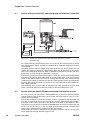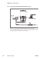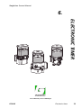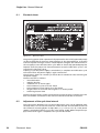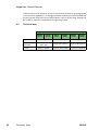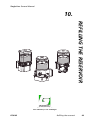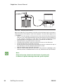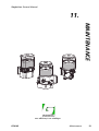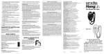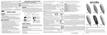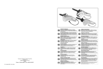
1
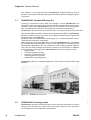
General Manual
Single Line
Automatic Greasing Systems
North American Market
EG0102
Your efficiency is our challenge!
your efficiency is our challenge
All rights reserved. No part of this manual may be copied and/or published by means of printing, photocopying,
microfilm or by any other means without prior written permission from Groeneveld. This applies also to the
drawings and diagrams appended.
Groeneveld reserves the right to change parts at any time, without prior or direct notice to the customer. The
contents of this manual may also be changed without prior notice.
This manual applies to the standard version of the product. Groeneveld cannot accept liability for any damage
arising from the use of specifications other than that supplied.
You are requested to contact Groeneveld technical service for information concerning adjustment, maintenance
work or repairs that is not described in this manual.
Whilst this manual has been prepared with the greatest possible care Groeneveld cannot accept responsibility for
any errors of the concequences of such errors.
Single Line General Manual
1.
1.
Introduction - - - - - - - - - - - - - - - - - - - - - - - - - - - - - - - - - - - - - - - - - 7
1.1.
1.2.
1.3.
2.
Conversions sizes and weights - - - - - - - - - - - - - - - - - - - - - - - - - - - 11
2.1.
2.2.
3.
4.
System summary - - - - - - - - - - - - - - - - - - - - - - - - - - - - - - - - - - - - - 17
Date of issue: January 2004
24
24
26
27
27
28
29
29
31
Electronic timer - - - - - - - - - - - - - - - - - - - - - - - - - - - - - - - - - - - - - - - - Adjustment of the cycle time interval - - - - - - - - - - - - - - - - - - - - - - - Testing the electronic timer - - - - - - - - - - - - - - - - - - - - - - - - - - - - - - - Alarm signals - - - - - - - - - - - - - - - - - - - - - - - - - - - - - - - - - - - - - - - - - Technical data - - - - - - - - - - - - - - - - - - - - - - - - - - - - - - - - - - - - - - - - - -
34
34
35
35
36
Operation - - - - - - - - - - - - - - - - - - - - - - - - - - - - - - - - - - - - - - - - - - - - - 38
Setting the number of brake applications - - - - - - - - - - - - - - - - - - - - - 39
Technical data - - - - - - - - - - - - - - - - - - - - - - - - - - - - - - - - - - - - - - - - - - 39
Metering units - - - - - - - - - - - - - - - - - - - - - - - - - - - - - - - - - - - - - - 41
8.1.
8.2.
8.3.
8.4.
8.5.
EG0102
Pneumatically operated piston pump - - - - - - - - - - - - - - - - - - - - - - - Pump unit - - - - - - - - - - - - - - - - - - - - - - - - - - - - - - - - - - - - - - - - - - - - Technical data - - - - - - - - - - - - - - - - - - - - - - - - - - - - - - - - - - - - - - - - - Electrically operated gear pump - - - - - - - - - - - - - - - - - - - - - - - - - - - Pump unit - - - - - - - - - - - - - - - - - - - - - - - - - - - - - - - - - - - - - - - - - - - - Technical data - - - - - - - - - - - - - - - - - - - - - - - - - - - - - - - - - - - - - - - - - Electric axial plunger pump - - - - - - - - - - - - - - - - - - - - - - - - - - - - - - - Pump unit - - - - - - - - - - - - - - - - - - - - - - - - - - - - - - - - - - - - - - - - - - - - Technical data - - - - - - - - - - - - - - - - - - - - - - - - - - - - - - - - - - - - - - - - - -
Pneumatic impulse counter - - - - - - - - - - - - - - - - - - - - - - - - - - - - - 37
7.1.
7.2.
7.3.
8.
18
18
19
20
21
22
Electronic timer - - - - - - - - - - - - - - - - - - - - - - - - - - - - - - - - - - - - - - 33
6.1.
6.2.
6.3.
6.4.
6.5.
7.
System with pneumatically operated pump and electronic timer/PLC System with pneumatically operated pump and impulse counter - - - System with pneumatically operated impulse counter - - - - - - - - - - - System with electrically operated impulse counter - - - - - - - - - - - - - - System with electrically operated pump - - - - - - - - - - - - - - - - - - - - - System with electric plunger pump - - - - - - - - - - - - - - - - - - - - - - - - - -
Pumps - - - - - - - - - - - - - - - - - - - - - - - - - - - - - - - - - - - - - - - - - - - - - 23
5.1.
5.1.1.
5.1.2.
5.2.
5.2.1.
5.2.2.
5.3.
5.3.1.
5.3.2.
6.
Sizes and weights conversions - - - - - - - - - - - - - - - - - - - - - - - - - - - - - - 12
Temperature conversions - - - - - - - - - - - - - - - - - - - - - - - - - - - - - - - - - 13
Principle of operation - - - - - - - - - - - - - - - - - - - - - - - - - - - - - - - - - 15
4.1.
4.2.
4.2.1.
4.2.2.
4.3.
4.4.
5.
GROENEVELD Transport Efficiency B.V. - - - - - - - - - - - - - - - - - - - - - - - - 8
GROENEVELD Greasing Systems - - - - - - - - - - - - - - - - - - - - - - - - - - - - - - 8
Single Line Automatic Greasing Systems - - - - - - - - - - - - - - - - - - - - - - - 9
q^_ib=lc=`lkqbkqp
Preface - - - - - - - - - - - - - - - - - - - - - - - - - - - - - - - - - - - - - - - - - - - - - 5
Types of metering units - - - - - - - - - - - - - - - - - - - - - - - - - - - - - - - - - - Operating principle - - - - - - - - - - - - - - - - - - - - - - - - - - - - - - - - - - - - - Phase A - - - - - - - - - - - - - - - - - - - - - - - - - - - - - - - - - - - - - - - - - - - - - - Phase B - - - - - - - - - - - - - - - - - - - - - - - - - - - - - - - - - - - - - - - - - - - - - - Phase C - - - - - - - - - - - - - - - - - - - - - - - - - - - - - - - - - - - - - - - - - - - - - - -
42
43
43
44
44
Table of contents
3
Single Line General Manual
9.
Other components - - - - - - - - - - - - - - - - - - - - - - - - - - - - - - - - - - - 45
9.1.
9.1.1.
9.2.
9.2.1.
9.3.
9.4.
Solenoid valve - - - - - - - - - - - - - - - - - - - - - - - - - - - - - - - - - - - - - - - - - Technical data - - - - - - - - - - - - - - - - - - - - - - - - - - - - - - - - - - - - - - - - - Pressure switch - - - - - - - - - - - - - - - - - - - - - - - - - - - - - - - - - - - - - - - - Technical data - - - - - - - - - - - - - - - - - - - - - - - - - - - - - - - - - - - - - - - - - Reservoir - - - - - - - - - - - - - - - - - - - - - - - - - - - - - - - - - - - - - - - - - - - - - Follower plate - - - - - - - - - - - - - - - - - - - - - - - - - - - - - - - - - - - - - - - - - -
46
46
47
47
48
48
10.
Refilling the reservoir - - - - - - - - - - - - - - - - - - - - - - - - - - - - - - - - - 49
11.
Maintenance - - - - - - - - - - - - - - - - - - - - - - - - - - - - - - - - - - - - - - - - 51
12.
Fault diagnosis - - - - - - - - - - - - - - - - - - - - - - - - - - - - - - - - - - - - - - 53
Date of issue: January 2004
4
Table of contents
EG0102
Single Line General Manual
3.
2.
Date of issue: January 2004
PREFACE
your efficiency is our challenge
Your efficiency is our challenge!
EG0102
Preface
5
Single Line General Manual
This general manual is a description of the Singleline Automatic Greasing System.
The intention is to provide clients with an insight into how the system works, what
the possibilities are and, briefly, maintenance aspects. Furthermore, you will find
the technical data of the various parts of the lubrication system in this manual.
The general manual can also be used as a user manual. The manual is built up of
different sections, indicated by chapter numbers. The numbering of pages and the
images re-starts with every new chapter.
In this manual, the following pictograms are used to bring an item to the user’s attention or to notify the user.
ATTENTION:
ATTENTION:
Important supplementary
information
is provided
for the user,
in users
the hopes
of
Important
supplementary
information
is brought
to the
attention,
so
preventing
errors
from
occurring.
trying to prevent problems occurring.
WARNING:
WARNING:
This pictogram notifies the user when the danger of physical injury or seThis pictogram notifies the user when the danger of physical injury or
vere
damage to the apparatus by inadequate operation is threatened.
severe damage by improper use should arise.
Date of issue: January 2004
6
Preface
EG0102
Single Line General Manual
4.
1.
Date of issue: January 2004
INTRODUCTION
your efficiency is our challenge
Your efficiency is our challenge!
EG0102
Introduction
7
Single Line General Manual
This chapter is a short presentation of GROENEVELD Transport Efficiency and its
products. The chapter ends with some general remarks about the Singleline greasing systems.
1.1
GROENEVELD Transport Efficiency B.V.
Investing in operational safety. With this thought in mind, GROENEVELD was
founded in 1971. The present, international network is administered from its headquarters in Gorinchem. GROENEVELD strives for an expansion of its leading position, achieved by the company’s solid image and customer-oriented policy.
GROENEVELD employees form
enthusiasm
and and
GROENEVELD
form aa team
team that
that daily
worksworks
everywith
daygreat
with great
enthusiam
dedication for its customers. Extensive automation makes a high working rate possible. The ISO 9001 standard is the basis for the guaranteed quality of GROENEVELD
products. Frequent contact with clients and an extensive dealer network guarantee
the good name of GROENEVELD.
We know what the entrepreneur needs today, not a ready-made product, but a
custom-made solution for automation.
New technologies offer new applications. Therefore GROENEVELD has a large budget available for the development of new cost-saving products. Our Research and
Development department not only collaborates with leading external organizations, but also with leading manufacturers of vehicles and machinery. In addition
to the Automatic Greasing System, GROENEVELD also delivers products such as:
•
speed limiters
•
on-board computer systems
•
automatic oil level controllers
•
reversing protection systems
•
temperature recording systems
GROENEVELD delivers a complete program of cost-saving and comfort-enhancing
products.
1.2
Date of issue: January 2004
Figure 1.1
GROENEVELD Head office
GROENEVELD Greasing Systems
GROENEVELD Automatic Greasing Systems ensure the daily maintenance of everything that has moving parts. They avoid unnecessary machinery wear and downtime and,thus,save cost and prevent exasperation.
8
Introduction
EG0102
Single Line General Manual
GROENEVELD greasing systems are used by, for example, production companies,
machinery used in service industries, agriculture, ships, the offshore industry and
the transport industry.
In the following list are the most important advantages:
•
increase of the service intervals, thus,less unnecessary down-time;
•
less wear of the lubricated parts because of accurate and constant lubricating;
•
reduced repair and replacement costs;
•
reduced unexpected down-time;
•
fewer production losses.
1.3
Single Line Automatic Greasing Systems
With a Single Line Automatic Greasing System, all lubrication points of a vehicle or
machine are automatically lubricated at the correct time with the correct dose.
Moreover, optimum grease or lube-oil distribution over the whole lubricating surface is achieved, because the lubrication takes place while the machinery or vehicle
is in operation. Every action is automatically carried out by the system. The user
needs only to refill the reservoir periodically.
The GROENEVELD Automatic Greasing Systems are designed with great care and
thoroughly tested to guarantee a long and fault-free life span, under the most
heavy operational conditions.
A well-functioning system requires:
•
correct assembly;
•
use of the prescribed type of grease or lube oil;
•
a periodic check of the functionality of the system.
The periodic check can easily be carried out at the same time as the normal maintenance of the machine or vehicle. Moreover, because of the careful choice of materials, the greasing system is nearly maintenance-free.
ATTENTION:
Date of issue: January 2004
An automatic greasing system avoids the time-consuming manual lubricating of important parts. Remember, however, that there can be lubricating
points that still have to be lubricated manually.
EG0102
Introduction
9
Single Line General Manual
Notes
Date of issue: January 2004
10
Introduction
EG0102
Single Line General Manual
5.
2.
Date of issue: January 2004
CONVERSIONS SIZES AND WEIGHTS
your efficiency is our challenge
Your efficiency is our challenge!
EG0102
Conversions sizes and weights
11
Single Line General Manual
2.1
Sizes and weights conversions
Metric
SAE
1 bar
= 14,7 psi
1 kilogram
= 2,2 lbs
1 cubic centimeter
= 0,061 cubic inches
1 liter
= 0,26 US gallon
1 liter
= 0,22 Imperial gallon
1 millimeter
= 0,03937 inch
1 psi
= 0,068 bar
1 lbs
= 0,454 kilogram
1 cubic inch
= 16,4 cubic centimeter
1 US gallon
= 3,79 liters
1 Imperial gallon
= 4,55 liters
1 inch
= 25,4 millimeters
Celsius
= (°F - 32) + 1,8
Fahrenheit
= (°C x 1,8) + 32
Date of issue: January 2004
12
Conversions sizes and weights
EG0102
Single Line General Manual
Temperature conversions
Celsius
Fahrenheit
-45
-49
-40
-40
-35
-31
-30
-22
-25
-13
-20
-4
-15
5
-10
14
-5
23
0
32
5
41
10
50
15
59
20
68
25
77
30
86
35
95
40
104
45
113
50
122
Date of issue: January 2004
2.2
EG0102
Conversions sizes and weights
13
Single Line General Manual
Notes
Date of issue: January 2004
14
Conversions sizes and weights
EG0102
Single Line General Manual
6.
3.
Date of issue: January 2004
PRINCIPLE OF OPERATION
your efficiency is our challenge
Your efficiency is our challenge!
EG0102
Principle of operation
15
Single Line General Manual
Each system consists of a pump with an integral reservoir, a control unit, a main
pipe, one or more metering unit blocks, metering units, secondary piping and connectors. Lubricant is transferred from the reservoir by the pump, via the main pipe,
to the metering unit blocks.
Each metering unit is connected by a secondary pipe to a lubrication point. An electronic timer,
timer, PLC
PLC or
ora apneumatically-operated
pneumatically operated
impulse
counter,
depending
impulse
counter,
depending
on on
whether there is a continuous electrical supply available, is used to determine when
lubrication occurs.
Generally only trailers and semi-trailers are equipped with a pneumatic (brake) impulse counter since they usually do not have a continuous electrical supply.
There are
are two
main types
types of
There
two main
of pump:
pumps:
• electrically-operated
electrically operatedpumps
pumps(with
(withelectronic
electronictimer
timeror
orPLC);
PLC)
• pneumatically-operated
pneumatically operatedpumps
pumps
(with
electronic
timer,
or pneumatic
(with electronic timer, PLC PLC
or pneumatic
impulse
counter).
impulse counter).
The electrically operated pump is used mainly for installations or vehicles without
a compressed air supply. The electrically -operated pump is also used for installations where a large lubricant delivery is required. The delivery is larger as the pump
operates for longer periods.
Date of issue: January 2004
16
Principle of operation
EG0102
Single Line General Manual
7.
4.
Date of issue: January 2004
SYSTEM SUMMARY
Yourefficiency
efficiencyis
isour
our challenge
challenge!
your
EG0102
System summary
17
Single Line General Manual
4.1
System with pneumatically -operated pump and electronic timer/PLC
Figure 4.1
System with pneumatically-operated pump and electronic timer
(schematically)
At a time preset by the electronic timer, the circuit to the solenoid valve is closed.
The solenoid valve opens and allows compressed air from the compressor to flow
to the pump.
The pump piston now rises under compressor pressure and forces grease into the
system. The lubricant pressure is dependent upon the air pressure on the piston
(this is the compressor pressure). With a compressor pressure of 125 psi and for a
pump with 9:1 ratio, the grease pressure is 1125 psi.
The metering units then simultaneously pass a fixed, pre-selected metered quantity
of grease to the points to be lubricated. To end the lubrication cycle the electronic
timer or PLC opens the electrical circuit closing the solenoid valve. Therefore ,the
compressed air supply to the pump is shut off and the piston reverts to atmospheric
pressure. This allows the piston to return to its starting position and the whole system is depressurized.
The metering units are then able to automatically refill themselves and are then
(after a minimum delay of 2 minutes) ready for the next lubrication cycle.
System with pneumatically-operated pump and impulse counter
As a rule, trailers and semi-trailers are equipped with a pneumatic (brake) impulse
counter and not with an electronic timer or PLC. This is because of a lack of a continuous electrical supply.
The standard version of the brake impulse counter is pneumatically-operated and
uses the air signal from the service line which is usually connected to the number
4 position of the trailer relay valve. This position may differ in the different countries; please contact your local dealer or GROENEVELD. In certain situations the signal line can be too long, as is the case with extended semi-trailers. Another relay
valve is then installed in the fixed part of the semi-trailer.
Alternatively ,an electrical version of the pneumatic impulse counter can be used,
which operates through the brake-light circuit.
18
System summary
EG0102
Date of issue: January 2004
4.2
Single Line General Manual
4.2.1
System with pneumatically-operated impulse counter
Figure 4.2
System with pneumatically-operated impulse counter (schematically)
Date of issue: January 2004
The vehicle air tank is connected to input P of the pneumatic impulse counter. Always draw air from the auxiliary tank. Port A on the pneumatic impulse counter is
connected to the compressed air connection on the underside of the pump. Port R
on the pneumatic impulse counter is connected to the vent above the main piston.
The other connection on this double banjo-union is an open vent.
EG0102
System summary
19
Single Line General Manual
4.2.2
System with electrically-operated impulse counter
Figure 4.3
System with electrically-operated impulse counter (schematically)
This corresponds broadly with that of a pneumatically operated impulse counter.
The signal impulse is derived from an electric signal.
Date of issue: January 2004
20
System summary
EG0102
Single Line General Manual
4.3
System with electrically-operated pump
Figure 4.4
System with electrically-operated pump (schematically)
Date of issue: January 2004
At a time set by the electronic timer or PLC, a gear pump under the grease reservoir
is started. The lubricant is pumped from the reservoir via the main pipe, to the metering unit blocks. The metering units then simultaneously allow a measured quantity of lubricant to be pressurized to the points to be lubricated. A pressure bypass
valve keeps the system at a preset pressure during the pumping cycle.
To end the lubrication cycle, the electronic timer or PLC opens the electrical circuit,
the gear pump then stops. Pressure in the output main (primary) pipe to the metering units then falls by means of a built-in pressure discharge valve. The metering
units then automatically refill themselves after which they are ready for the next
lubrication cycle.
EG0102
System summary
21
Single Line General Manual
4.4
System with electric plunger pump
Figure 4.5
System with electric plunger pump (schematically)
22
System summary
EG0102
Date of issue: January 2004
GROENEVELD Automatic Greasing Systems with electrically-driven pumps are usually employed on vehicles or machines on which electric power is always available.
An electric pump is also the best choice if the lubricant demand of the system is
high.
The control unit - an advanced electronic timer, for instance - holds a number of
system control variables, such as the lubrication interval and the duration of the lubrication cycle. The control unit is able to process and store all functional errors that
may occur and automatically maintains an electronic log book. If the greasing system requires action, the controller will generate an alarm signal (i.e. if the reservoir
needs to be refilled).
At a given point in time, the control unit will start the pump and lubricant will be
pressed through the primary line to the distributors and, consequently, to the dosage metering units. Each metering device then forces - powered by the grease pressure - an exact amount of grease through the secondary lines to the grease points.
All metering units act simultaneously. The amount of lubricant that goes to each of
the grease points depends on the type of metering device installed.
A pressure control valve - built into the pump unit - maintains a constant pressure
of 1500 psi in the system during the lubrication cycle (i.e. while the pump runs).
If the grease pressure exceeds 1500 psi this valve will redirect the grease back toward the reservoir.
During the lubrication cycle, the integrated pressure switch must report to the control unit that the required pressure has been attained (at least 1029 psi). If the control unit does not receive this signal it will generate an alarm signal.
The lubrication cycle ends when the control unit stops the pump. The pressure in
the primary line then slowly drops to zero, via an electrically- controlled relieve
valve. The metering units will then be able to reset themselves and will be ready
for the next lubrication cycle after about two minutes.
Single Line General Manual
8.
5.
Date of issue: January 2004
PUMPS
Your
efficiencyisisour
ourchallenge
challenge!
your
efficiency
EG0102
Pumps
23
Single Line General Manual
5.1
Pneumatically -operated piston pump
5.1.1
Pump unit
1.
2.
3.
4.
5.
6.
7.
8.
9.
10.
11.
12.
13.
14.
15.
16.
17.
reservoir with follower plate
air venting channel
grease channel
return channel to reservoir
main line connection
pressure channel
return valve
non-return valve
grease pressure colour
color indicator
indicator
compressed air connection
main air piston
spring
filler connector
small grease piston
grease chamber
flapper valve
connection to reservoir
Date of issue: January 2004
Figure 5.1
24
Pumps
Pneumatically-operated pump
EG0102
Single Line General Manual
Date of issue: January 2004
If pressure is applied via the compressed air connection (10) the main piston (11)
will be forced upwards applying pressure to the lubricant in chamber (15). The pressure in chamber (15) forces valve (16) against the seat. The connection (17) to the
reservoir (1) is thus closed.
The lubricant leaves the chamber (15) via a channel (3) through the non-return
valve (8) into the main or primary line. The metering units are brought under full
pump pressure passing their metered quantities of lubricant into the lubrication
points. As a result of the pressure differential at the return valve (7) the return
channel (4) remains closed.
At the end of the complete lubrication cycle the air pressure under the main piston
(11) falls, allowing the piston to be pushed downward by the spring (12). At the
same time flapper valve (16) is released and, because of the reduced pressure in the
chamber (15), lubricant is drawn from the reservoir.
The non-return valve (8) prevents grease from the system piping and metering units
from flowing back into the chamber (15).
The pressure in the main pipe opens the return valve (7) via the channel (6). This
allows the pressure of the lubricant to flow via the channel (4) to the reservoir. The
metering units, with this pressure drop can now automatically refill themselves following which, they are ready for the next lubrication cycle.
A manometer can be connected to the lubricant channel showing the pressure in
indithe main line. It is also possible to replace this manometer by a pressure colour
color indicator (9). At the start of the lubrication cycle, this will be red as a result of the air
pressure, and will change to green at the end of the cycle, due to the pressure.
Green,thus, indicates that the pump has worked and that sufficient pressure has
built up in the grease line system. If the color remains red, this means that insufficient pressure has built up in the system. This could be caused by leakage from the
main line.
EG0102
Pumps
25
Single Line General Manual
5.1.2
Technical data
Grease pumps:
part number
reservoir capacity
36201
68801
35501
4 liters
6 liters
8 liters
delivery
42 cc / stroke
ratio
grease pressure
9:1
1125 psi (for an air pressure of 125 psi)
maximum grease pressure
temperature range
weight
1500 psi
-13°F to +176°F (NLGI 0 grease)
13.86 lbs
14.85 lbs
15.84 lbs
part number
37101
reservoir capacity
4 liters
delivery
weight
8 liters
9:1
1125 psi (for an air pressure of 125 psi)
maximum grease pressure
temperature range
6 liters
60 cc / stroke
ratio
grease pressure
43001
1500 psi
-13°F to +176°F (NLGI 0 grease)
16.54 lbs
17.53 lbs
18.52 lbs
Oil pumps:
part number
reservoir capacity
00511
06511
4 liters
8 liters
delivery
42 cc / stroke
oil pressure
9:1
1125 psi (for an air pressure of 125 psi)
maximum grease pressure
1500 psi
temperature range
weight
26
Pumps
-13°F to +176°F
13.32 lbs
14.3 lbs
EG0102
Date of issue: January 2004
ratio
Single Line General Manual
5.2
Electrically -operated gear pump
5.2.1
Pump unit
Date of issue: January 2004
1.
2.
3.
4.
5.
6.
7.
8.
9.
10.
11.
follower plate
low level indicator switch
pressure control valve
connector fitting
vent opening
main pipe line connector
pressure switch connection
electro-motor
filler connector
gear pump
reservoir
Figure 5.2
EG0102
Electrically-operated pump
Pumps
27
Single Line General Manual
The gear pump (9) is activated by the electronic timer. The lubricant will now be
pumped from the reservoir (10) through the main pipe line (6) to the metering unit
distribution blocks. The pump remains in operation throughout the entire cycle period. This cycle or impulse period is 3 minutes, when the standard version of the
electronic timer is used. The pump builds up the lubricant pressure during the cycle.
When the pressure reaches 838 psi, the pressure control valve (3) opens, lubricant
is then no longer pumped into the main line but returns to the reservoir. The pressure is thus limited to 838 psi.
The standard version of the electrically- operated pump is fitted with a pressure
switch (7). If, during the lubrication cycle, the pressure does not rise above 588 psi
the electronic timer or PLC will sound an alarm signal. A level indicator switch (2)
(not in all versions) provides an alarm signal if the lubricant in the reservoir falls below a certain minimum level.
On the right-hand side between the connector for the primary line (6) and the connector fitting (4),there is a right-angle connector for air venting and overflow (5).
When filling the reservoir with lubricant the air above the follower plate escapes.
This air flows downward through an opening in the piston line and leaves the
pump via the right-angle connector (5). The escape of a small quantity of lubricant
via this connector during venting is quite normal.
(A version with the connections for the primary line and for the connector on the
left-hand side of the pump can also be supplied if required.)
5.2.2
Technical data
Gear pump:
part number
without level indicator
switch:
530.01 (12 V)
522.01 (24 V)
with level indicator
switch:
531.01 (12 V)
523.01 (24 V)
current consumption
8A
4A
reservoir capacity
2.7 litres
2.7 litres
delivery
120 cc/minute
(NLGI 0 grease) at 20 °C
120 cc/minute
(NLGI 0 grease) at 20 °C
grease pressure
855 psi
855 psi
temperature range
-4°F to +158°F
(NLGI 0 grease)
-4°F to +158°F
(NLGI 0 grease)
at extreme circumstances ,please consult your local
organization
GROENEVELD-organization
28
Pumps
14.74 lbs
Date of issue: January 2004
weight
14.74 lbs
EG0102
Single Line General Manual
5.3
Electric axial plunger pump
5.3.1
Pump unit
follower piston
reservoir
guide rod of follower
level switch
plunger pump
coupling for primary grease line
electric connector
pressure switch
electric motor
return valve
filler port
overflow port
filter
pressure control valve
Date of issue: January 2004
1.
2.
3.
4.
5.
6.
7.
8.
9.
10.
11.
12.
13.
14.
Figure 5.3
EG0102
The electric plunger pump
Pumps
29
Single Line General Manual
The actual pump (5) of the unit consists of six fixed cylinders amid a ring duct. The
six plungers are driven by the electric motor (9) through a mechanical transmission.
In the channel between the ring duct and the output port (6) of the pump unit, a
pressure control valve (14) and an electrically operated return valve (10) have been
incorporated. The pressure control valve is used to maintain a constant grease pressure during the pump cycle. The return valve allows the grease pressure in the system to fade after the pump cycle has ended.
The standard electric plunger pump is fitted with a pressure switch (8) which is used
to check that the required grease pressure is attained during the pump cycle. The
optional low level switch (4) in the reservoir will cause the control unit to generate
an alarm signal when the level of the lubricant in the reservoir becomes too low
and needs to be replenished.
The pump is electrically-connected with the control unit through a connector (7).
The reservoir (2) is mounted on top of the pump unit. The reservoir is filled via the
filler port (11) at the side of the pump unit. A filter (13) prevents contaminations
from entering the reservoir. Any bubbles of air that might be introduced in the lubricant while filling the reservoir can escape to the space above the follower piston
(1) through the overflow port (12) and a channel in the guide rod (3). If the reservoir is - inadvertently - filled to a level above its maximum level, this excess lubricant
is also allowed to escape in this way.
Date of issue: January 2004
30
Pumps
EG0102
Single Line General Manual
5.3.2
Technical data
Grease pump:
partnumber
160.22
161.22
162.22
214.22
315.22
339.22
50
25
25
50
25
25
1500
psi
1500
psi
1500
psi
1500
psi
1500
psi
1500
psi
content reservoir (litres)
8
8
4
4
4
4
supply voltage (V dc)
12
24
24
12
12
24
nominal current (A)
8
4
4
8
8
4
grease output (cc/min)
(see remark)
max. grease pressure (psi)
electrical connection
(connector):
pin 1: plus
pin 2: minus
pin 3: grease pressure
switch
pin 4: grease level switch
4-pin
follower piston in reservoir
yes
yes
yes
yes
yes
yes
integrated pressure switch
yes
yes
yes
yes
yes
yes
optional
optional
optional
optional
optional
optional
level switch
operating temperatures
(°F): 0-grease 00, 000, or of +23°F . . . . +176°F
LT-grease
(operating temperatures below +5°F)
weight
21.56
lbs
21.56
lbs
19.36
lbs
19.36
lbs
19.36
lbs
19.36
lbs
REMARK:
Date of issue: January 2004
The output of the pump is specified in cubic centimetres per minute. If the
greasing system is to operate properly however, the pump should have
supplied the total quantity of grease required by the system before 70% of
the lubrication cycle has expired. The length of the cycle must be set
accordingly. This will guarantee that the grease pressure reaches a value of
at least 1176 psi and that the pressure switch in the pump will report this
fact to the control unit. If the control unit does not receive this signal, it will
generate an alarm signal.
EG0102
Pumps
31
Single Line General Manual
Oil pumps:
part number
61522 (24Vdc)
F172672 (24Vdc)
current consumption
4A
4A
reservoir capacity
4 liters
8 liters
delivery
50 cc/minute at +68°F
50 cc/minute at +68°F
oil pressure
855 psi
855 psi
temperature range
-4°F to +158°F
-4°F to +158°F
at extreme circumstances ,please consult your local
organization
GROENEVELD-organization
weight
20.24 lbs
22.44 lbs
Date of issue: January 2004
32
Pumps
EG0102
Single Line General Manual
9.
6.
Date of issue: January 2004
ELECTRONIC TIMER
your
efficiency
Your
efficiencyisisour
ourchallenge
challenge!
EG0102
Electronic timer
33
Single Line General Manual
6.1
Electronic timer
687.01
Figure 6.1
Electronic timer
The greasing system (with a pneumatically-operated or electrically-operated pump)
can be controlled by an electronic timer (Figure 6.1). The timer produces, at set time
intervals impulses lasting 3 minutes. These impulses energize the solenoid valve in
the air supply to start the lubrication cycle. With an electrically operated pump the
impulses start the pump. The interval between successive lubrication cycles is adjusted on the electronic timer.
If during a cycle the power supply is switched off, a complete new lubrication cycle
will restart when the power supply is again switched on.
The electronic timer has a memory in which data is stored even after switching off
the power supply.
The data stored is as follows:
•
interval duration
•
impulse duration
•
conditions for an alarm signal
•
total number of cycles since first fitted
•
total number of alarm signals since first fitted
•
longest series of successive alarm signals in a certain period
•
remaining interval time
The data in the memory can be recovered using a special test or read-out unit. This
device should be connected via the socket on the left-hand side of the timer.
Adjustment of the cycle time interval
The interval time between two successive lubrication cycles can be adjusted using
the step switch. One of ten time intervals can be selected. The standard version has
time intervals increasing by 0.5 h steps (0.5 h, 1 h, 1.5 h etc. to 5 h). If the power
supply is switched off during a cycle the cycle will be ended. When the power supply is switched on again a complete new cycle will be started.
34
Electronic timer
EG0102
Date of issue: January 2004
6.2
Single Line General Manual
6.3
Testing the electronic timer
The various electronic timer functions can be tested as follows:
Test 1, step switch test:
•
•
•
•
•
•
•
•
This test checks the step switch contacts in all positions.
Set the step switch to position ‘test A’.
Activate the electronic timer by switching on the ignition.
Press the ‘test’ button.
Wait for the audible alarm signal then release the ‘test’ button.
Within 5 seconds turn the step switch to the required interval time position. Each position produces a number of signals: position 1 gives one signal, position 2 two signals etc.
The switch can be set to all positions; positions ‘test A’ and ‘test B’ will not
produce an alarm signal.
End the test by switching off the ignition.
Test 2, accelerated cycle test:
•
•
•
•
•
•
•
Set the step switch to position ‘test A’.
Press and hold the ‘test’ button.
Switch the ignition on while still keeping the ‘test’ button pressed in.
The alarm signal buzzer will now sound. The ‘test’ button must be pressed
as long as the alarm signal continues.
Within 5 seconds of the end of the alarm signal turn the step switch to the
required position.
The electronic timer is now fully operational; the time intervals are now 1/
20 of their usual times.
End the test by switching off the power supply.
Test 3, normal system test:
•
•
Switch the ignition on.
Press the ‘test’ button; a normal lubrication cycle will then follow. The
switch can be set in any position except ‘test A’ or ‘test B’.
After this test the electronic timer will work at the interval set.
The ‘test B’ position is only for use with the test or read-out unit.
6.4
Alarm signals
Date of issue: January 2004
Alarm signals can be generated by the electronic timer in various circumstances.
The standard version uses a built-in buzzer. In other versions another (external)
alarm indicator can be fitted, for example a lamp.
The alarm signal is generated in the following situations:
•
After reaching 70% of the cycle time (70% of 3 minutes = 2 minutes) the
pressure switch should have connected to earth. If this is not the case because insufficient pressure has been built up - then a continuous alarm
signal is generated.
•
If a level indicator switch is fitted to an electrically- operated pump, an
intermittent alarm is generated when the level of the lubricant in the
reservoir falls below a set minimum. This signal will be generated throughout
the entire cycle. If, moreover, insufficient pressure is built up, the pressure
alarm will take over after 2 minutes, causing a change in the frequency of the
alarm signal.
•
The electronic timer runs a self-test after the power supply is switched on; if
there is a fault condition an intermittent alarm is generated. This can occur if
no interval is selected by the step switch.
EG0102
Electronic timer
35
Single Line General Manual
If the electronic timer sounds an alarm to indicate that the timer or greasing system
is not functioning properly, it is strongly advised to examine (or have examined) the
greasing system and,if necessary,to make repairs. If this is left too long, damage can
be caused to either the installation or the greasing system.
6.5
Technical data
part number
099.01
(12 V)
cycle time
cycle
intervals
alarm
032.01
(24 V)
676.02
(12V)
675.02
(24V)
678.02
(12V)
677.02
(24V)
3 minutes
2 minutes
3 minutes
steps of 30 minutes
(0.5 - 5 h)
steps of 5 minutes
steps of 30 minutes
built-in buzzer
internal relay (16A)
internal relay(16A)
Date of issue: January 2004
36
Electronic timer
EG0102
Single Line General Manual
10.
7.
Date of issue: January 2004
PNEUMATIC IMPULSE COUNTER
your
challenge
Yourefficiency
efficiency is
is our
our challenge!
EG0102
Pneumatic impulse counter
37
Single Line General Manual
7.1
Operation
1
2
P
A
R
solenoid valve
screw for manual operation (test)
compressed air connection
pump connection
venting outlet
Figure 7.1
1
2
P
A
R
Electrically-operated brake impulse counter
signal air
screw for manual operation (test)
compressed air connection
pump connection
venting outlet
Figure 7.2
Pneumatically-operated brake impulse counter
38
Pneumatic impulse counter
EG0102
Date of issue: January 2004
The pneumatic impulse counter starts the lubrication cycle after a set number of
pulses. The electrically -operated counter (Figure 7.1) is activated by an electric signal. The solenoid valve of the pneumatic impulse counter is energized, causing the
operating cam to be rotated. With a pneumatically-operated impulse counter (Figure 7.2) activation is through pulses from the pneumatic system before the relay
valve. The compressed air operates a piston, which in turn rotates the operating
cam.
After a preset number of pulses the operating cam opens the air valve through
which compressed air passes to the pump.
The lubrication cycle then begins. After a further number of pulses, depending on
the setting of the counter, the pump is vented through the venting outlet R.
Single Line General Manual
7.2
Setting the number of brake applications
Figure 7.3
Setting the brake impulse
The number of pulses required for the counter to activate the pump, is set as follows:
•
Remove the transparent cover.
•
Set the distance (Figure 7.3) between the left-hand side of the striker (1) and
the head of the adjusting bolt (2). The distances equivalent to a specific
number of pulses are shown on the transparent cover. A feeler-gauge (3) is
fixed to the inside of the cover and can be used to set this distance. The tool is
marked with the number of pulses related to each thickness.
•
Tighten the adjustment bolt lock nut (4).
•
Replace and secure the cover.
REMARK:
Setting the pneumatic impulse counter is easier when the pneumatic line is
under pressure. This moves the cam striker to the right so that the distance
between the striker and the adjustment bolt can be measured.
7.3
Technical data
part number
Date of issue: January 2004
074.01
pneumatically operated
EG0102
003.01
electrically operated
cycle time
minimum 2 brake impulses
minimum 2 brake impulses
cycle intervals
10 - 80 brake impulses
10 - 80 brake impulses
Pneumatic impulse counter
39
Single Line General Manual
Notes
Date of issue: January 2004
40
Pneumatic impulse counter
EG0102
Single Line General Manual
11.
8.
Date of issue: January 2004
METERING UNITS
Your
efficiency
ourchallenge
challenge!
your
efficiency
isisour
EG0102
Metering units
41
Single Line General Manual
Figure 8.1
Distribution block with metering units
Linesystem,
system,
each
with
There are 11 metering unit types (1) available for the Single
Singleline
each
with
a differing metered lubricant quantity. By careful selection of the type of metering
unit each lubrication point can be provided with the right quantity of lubricant.
The metering units are fitted in groups on distribution blocks (2); this is a cast brass
distribution block to which the primary (main) line(3) is connected. The blocks are
available with several ports or outlets to which metering units can be connected.
The unused outlets should be blanked-off.
The metering units are also made of brass and are, because of their enclosed design, exceptionally suitable for use in dirty and dusty conditions. It is not advisable
to open the metering units as this allows the entry of dirt, and, thus,is a potential
cause of faults.
8.1
Types of metering units
The delivery (per lubrication cycle) of a metering unit is determined by the number
and thickness of the spacers mounted between the head and the housing of the
metering unit (Figure 8.2). The following metering units are available:
Date of issue: January 2004
Figure 8.2
42
Metering units
Types of metering units
EG0102
Single Line General Manual
8.2
Operating principle
Figure 8.3
Metering unit in initial position
Figure 8.3 illustrates a new metering unit, one that has not yet been filled with
grease. Item (1) in this figure is the spacer, which determines the delivery of the metering unit (see previous paragraph).
The metering units that are used in your greasing system may differ externally, or
even internally, from the one illustrated here. However, the operating principle is
always the same.
Date of issue: January 2004
8.3
Phase A
Figure 8.4
Metering unit in phase A
The pump presses the grease into grease channel (1). The grease pushes plunger (4)
past channel (2). The grease now fills chamber (3) and pushes plunger (5) to the
right. The stroke length of plunger (5) will determine the amount of grease that
will be pressed through the secondary grease line to the grease point. This stroke
length - hence the capacity of chamber (3) – is determined by the number and thickness of the spacers (Figure 8.3/1).
EG0102
Metering units
43
Single Line General Manual
8.4
Phase B
Figure 8.5
Metering unit in phase B
When the pump stops and as the grease pressure drops, spring (7) (Figure 8.5) will
push plunger (4) back to the left, closing off channel (1).
O-ring (9) prevents grease from being sucked back from chamber (6). Plunger (5) is
pushed back by spring (10) and presses the grease in chamber (3), via channel (2),
to chamber (8).
8.5
Phase C
Metering unit in phase C
During the next lubrication cycle, the same happens as in phase A. Chamber (8) (Figure 8.6), however, is now filled with grease. As plunger (4) moves right under influence of the grease pressure, the grease in chamber (8) is pressed, via chamber (6)
and the secondary grease line, to the grease point.
During all this, O-ring (9) is pressed outward to allow the grease to leave
chamber (8).
44
Metering units
EG0102
Date of issue: January 2004
Figure 8.6
Single Line General Manual
12.
9.
Date of issue: January 2004
OTHER COMPONENTS
your efficiency is our challenge
EG0102
Other components
45
Single Line General Manual
9.1
Solenoid valve
Figure 9.1
Solenoid valve
The solenoid valve (Figure 9.1) between the air tank and the pneumatically-operated pump (usually fitted to the pump) is a normally closed, free venting type. The
valve is connected electrically by an M24 screw connector.
9.1.1
Technical data
part number
184.08 (12 V)
183.08 (24 V)
type
normally-closed with
open venting
normally-closed with
open venting
operating pressure
maximum 150 psi
maximum 150 psi
power requirement
maximum 8 W
maximum 8 W
screw thread
M24
M24
Date of issue: January 2004
46
Other components
EG0102
Single Line General Manual
9.2
Pressure switch
Figure 9.2
Pressure switch
A pressure switch is included in the lubrication system (in the main pipe) to provide
an alarm for too low a pressure in the system during the lubrication cycle.
This switch closes at a pressure of 600 psi, making a connection to earth. If this does
not happen during the lubrication cycle, because insufficient or no grease pressure
is generated, an alarm will be given. During the remaining cycle time there will be
an intermittent alarm signal. This alarm will be repeated after a preset time if the
problem is not corrected.
An M24 screw connector connects the switch electrically.
For a system with a pneumatically-operated pump the pressure switch is fitted to a
distribution block. The electrically-operated pump is provided with a built-in pressure switch.
9.2.1
Technical data
part number
225.01
normally-open
switching pressure
600 psi
connection
2-wire
screw thread
M24
Date of issue: January 2004
type
EG0102
Other components
47
Single Line General Manual
9.3
Reservoir
Figure 9.3
Pump
The reservoir (2) is made from impact-resistant plastic that can withstand the influences of fluctuating temperatures. The reservoir can hold a quantity of lubricant
that in most cases is sufficient for about 4 months, depending on the number of
grease points.
The minimum level (5 cm) is marked by a label (3) on the reservoir.
9.4
Follower plate
In the standard reservoir,a follower plate is placed above the level of the lubricant
(Figure 9.3/1). This plate follows the level of the lubricant; as the level falls,the follower plate falls with it under the action of a tension spring. The follower plate prevents the increase of air into the lubricant and any consequent soaping of the
lubricant. Funneling of grease as the level falls is also prevented. The follower plate
also wipes the reservoir wall clean. This allows the level of the lubricant to be
checked easily at a glance.
Date of issue: January 2004
48
Other components
EG0102
Single Line General Manual
13.
10.
Date of issue: January 2004
REFILLING THE RESERVOIR
your efficiency is our challenge
Your efficiency is our challenge!
EG0102
Refilling the reservoir
49
Single Line General Manual
Figure 10.1
Filling the grease reservoir
When the lubricant in the reservoir has fallen to the minimum level it must be refilled. Generally a filler pump is used for this purpose. The procedure (Figure 10.1)
is as follows:
•
With a new filler pump (or filling hose) the hose should first be primed with
lubricant. This avoids the pumping of air into the reservoir. For this the ball (1)
in the snap-on connector on the filler hose should be depressed while
pumping lubricant through the hose until it is filled with the lubricant.
•
Remove the dust cap from the filler connector.
•
Carefully clean the filler connector and the connector on the filler hose.
•
Secure the filler hose to the filler connector.
•
Fill the reservoir to not more than the maximum level (2 cm below the top of
the reservoir) or until the follower plate meets its stop.
•
Replace the dust cap on the filler connector.
•
There is a filter within the filler connector in the reservoir. If pumping is very
difficult the filter could be blocked. In this case, dismantle and clean the filter.
Note:
Note:
Keep main pump raised from the bottom of grease pail, to insure no plastic
Keep main
shavings
enterpump
greaseraised
system.from the bottom of grease pail,
to ensure no plastic shavings enter the grease system.
Date of issue: January 2004
50
Refilling the reservoir
EG0102
Single Line General Manual
14.
11.
Date of issue: January 2004
MAINTENANCE
your
isour
ourchallenge!
challenge
Your efficiency
efficiency is
EG0102
Maintenance
51
Single Line General Manual
Maintenance of
Automatic
Greasing
System
Maintenance
of Groeneveld's
the Groeneveld
Automatic
Greasing
Systemcan
canbe
becombined
combined with
with
normal
vehicle
or
installation
maintenance.
normal vehicle or installation maintenance.
Check the pump, paying particular attention to:
•
the level of the lubricant (top up in time),
•
external damage.
Check the electronic timer with particular reference to the correct operation of the
various functions.
For this an accelerated test should be carried out (see section 6).
Check the brake impulse counter and pay attention to the manometer on the
pump.
Operate the brake impulse counter manually by means of the screw.
Check the entire system and in particular for:
•
damage of tubing;
•
operation of the metering units.
If a high pressure (steam) cleaner is used to clean the vehicle or installation, the lubrication system pump should be avoided to prevent any possible entry of water
through the venting openings. Water will not enter under normal operating conditions.
REMARK:
When an automatic greasing system is used, time-consuming lubricating by
hand is largely replaced. However, do not forget that, for example, the universal joints of the propeller shaft still have to be greased manually.
Date of issue: January 2004
52
Maintenance
EG0102
Single Line General Manual
15.
12.
Date of issue: January 2004
FAULT DIAGNOSIS
your
efficiency
is is
our
Your
efficiency
ourchallenge
challenge!
EG0102
Fault diagnosis
53
Single Line General Manual
Fault
1. All points to be lubricated are dry.
Cause
Action
a. Pump reservoir is empty.
a. Fill the reservoir (see section 10).
b. Reservoir filled with
grease that is too thick and
unsuitable for the system.
b. Remove and clean the
reservoir. Refit and fill the
reservoir with the correct
grease. Remove the end
plugs from the distribution
blocks and pump the old
grease out of the system.
c. Main pipe leaking.
c. Repair the line and bleed
the system if a new piece of
piping has been fitted.
d. Electronic timer, PLC or
pneumatic impulse counter
not set correctly.
d. Reset the electronic
timer, PLC or brake impulse
counter.
If there is another cause,
please consult your dealer.
2. Pump does not work or
does not reach working
pressure.
a. Pneumatically-operated
pump: No or too-low air
pressure.
a. Ensure there is an air
pressure of 90 to 125 psi.
b. Piston does not rise.
b. Dismantle the cover of
the pump casing and clean
the piston.
If there is another cause,
please consult your dealer.
3. One or more lubrication
points are dry while the
others receive sufficient
grease.
a. Repair or replace the
line.
b. Inoperative metering
unit.
b. Remove the metering
unit and fit a new unit.
4. A lubrication point
receives too much grease.
a. Internal leak in the
metering unit.
a. Remove and clean the
metering unit or fit a new
unit.
5. Pneumatically-operated
pump: Solenoid valve fails
to operate or does not
operate correctly.
a. Bad or open electrical
connections.
a. Check the electrical circuit and connections to the
solenoid valve. Check the
valve with direct current
bypassing the electronic
timer. Watch out for shortcircuits!
b. Solenoid valve internally
fouled with water and/or
rust from the vehicle air system.
b. Dismantle, clean and
refit the valve or fit a new
valve. Clean the vehicle air
system.
Fault diagnosis
EG0102
Date of issue: January 2004
54
a. Break in the secondary
tubing.
Single Line General Manual
Fault
Cause
Action
a. Short circuit.
a. Check wiring and test
solenoid.
7. Electronic timer does not
operate.
a. Fuse blown.
a. Fit new fuse.
8. Too much grease at all
lubrication points.
a. System greasing frequency does not correspond with vehicle
operating conditions.
b. Reduce the greasing frequency. Do not be too sparing, it is better to grease
too much than too little.
9. Alarm buzzer in electronic timer sounds intermittently.
a. Grease level in the reservoir below the minimum.
a. Fill the reservoir (see section 10).
a. System not reaching
working pressure.
a. Top up the reservoir with
grease and/or repair the
main pipe, check the pump
pressure with a manometer.
c. No cycle time interval
selected on the electronic
timer.
c. Set a cycle time interval
on the electronic timer.
Date of issue: January 2004
6. Continuous buzzing from
the electronic timer.
EG0102
Fault diagnosis
55
Single Line General Manual
Notes
Date of issue: January 2004
56
Fault diagnosis
EG0102
Groeneveld Australia Pty. Ltd.
Groeneveld Information Technology B.V.
18 - 20 Mc Dougall Road
P.O.Box 787
Sunbury, Vic 3429, AUSTRALIA
Tel.: +61 397 4099943
Fax: +61 397 4099665
Stephensonweg 12, 4207 HB Gorinchem
THE NETHERLANDS
Tel.: +31 183 641400
Fax: +31 183 641690
Groeneveld New Zealand Ltd.
Groeneveld Belgium NV/SA
Industriezone Hogenakkerhoek
Heirbaan 3, B-9150 Kruibeke, BELGIUM
Tel.: +32 3 8979860
Fax: +32 3 8979861
58 Newton Road
P.O.Box 4509
Mt Maunganui, NEW ZEALAND
Tel.: +64 7 5720684
Fax: +64 7 5724587
Groeneveld do Brasil Ltda
Groeneveld Polska Sp. Z.o.o.
Rua Sabiá 775, Moema
04515-001 Sao Paulo, SP, Brasil
Tel: + 55 (11) 5052 5259
Fax: + 55 (11) 5052 7002
Ul. Ostrowska 476
61 - 342 Poznan, POLAND
Tel.: +48 61 8726207/08/09
Fax: +48 61 8798166
Groeneveld CPL Systems Canada Inc.
Groeneveld South Africa
7065
Road
R.R.#3.
8450 Twiss
Lawson
Road,
Unit 5
Milton,
Ontario,
L9T 0J8Ontario,
CANADA
LOP
1BO
Campbellville,
CANADA
Tel: +
+1
800 875
2631017
1760
Tel:
1 905
Fax:+11905
Fax:
905875
875 2125
2125
Unit 65, Sunny Rock Park
Sun Rock Close, Germiston
1401 SOUTH AFRICA
Tel.: +27 11 4503977
Fax.: +27 11 4503980
Groeneveld Deutschland GMBH
Bullermanshof 2B
47441 Moers-Hülsdonk, DEUTSCHLAND
Tel.: +49 2841 793520
Fax: +49 2841 7935222
Groeneveld France
53, rue Antoine Condorcet
38090 Vaulx Milieu, FRANCE
Tel.: +33 4 74999333
Fax: +33 4 74999350
Groeneveld France IT
53, rue Antoine Condorcet
38090 Vaulx Milieu, FRANCE
Tel.: +33 4 74999333
Fax: +33 4 74999350
GINTEC
Active Safety Ltd.,
49, Hasharoshet 1st
Karmiel, 20101, ISRAËL
Tel.: +972 4 9882220
Fax: +972 4 9883179
Groeneveld Ibérica S.A.
Pol. Ind. Mercederias,
C/. Font de Sant Llorenç 36
08720 Vilafranca del Penedès (Barcelona), SPAIN
Tel.: +34 93 8171822
Fax: +34 93 8172061
Groeneveld Transport Efficiency U.K. Ltd.
The Greentec Centre
Gelders Hall Road, Shepshed
Loughborough, Leicestershire, LE12 9NH
UNITED KINGDOM
Tel.: +44 1509 600033
Fax: +44 1509 602000
Groeneveld Transport Efficiency, Inc.
1130 Industrial Parkway North
Brunswick, Ohio 44212, U.S.A.
Tel.: +1 330 2254949
Toll free: +1 800 5867283
Fax: +1 330 2255213
Mobile: +1 800 5867283
Groeneveld Pacific West L.L.C.
Groeneveld L’Efficienza nel Trasporto
S.r.l. (GENT)
Via Chiari 100
23868 Valmadrera (Lecco), ITALIA
Tel.: +39 3 41200536
Fax: +39 3 41201539
Groeneveld Italia (GRIT)
Via Chiari 100
23868 Valmadrera (Lecco), ITALIA
Tel.: +39 3 41201133
Fax: +39 3 41201158
Groeneveld Transport Efficiency B.V.
Postbus 777, 4200 AT Gorinchem
THE NETHERLANDS
Tel.: +31 183 641400
Fax: +31 183 624993
1089 Valentine Avenue SE
Pacific, WA 98047, U.S.A.
Tel.: +1 253 8633700
Fax: +1 253 8633131
Mobile: +1 253 6061838
Groeneveld Atlantic South, Inc.
9633 Palm River Road
Tampa, FL 33619, U.S.A.
Tel.: +1 813 6265600
Fax: +1 813 6265540
Mobile: +1 813 7650928
Groeneveld USA • Brunswick (OH) 1 330 225 4949 • Pacific (WA) 1 253 863 3700
Groeneveld Canada • 1 905 875 1017 • Ottawa (ON) 1 800 263 1760 • Edmonton (AB) 1 800 263 1760
Winnipeg (MB) 1 800 263 1760 • Surrey (BC) 1 888 326 1971 • Atlantic 1 902 883 2234
www.groeneveld-group.com
Groeneveld USA • Brunswick (OH) 1 330 225 4949 • Pacific (WA) 1 253 863 3700
GroeneveldCanada
Transport
Efficiency
B.V.,
Stephensonweg
4207 (ON)
HB Gorinchem,
4200 AT(AB)
Gorinchem,
Groeneveld
• Milton
(ON)
1 905
875 1017 • 12,
Ottawa
1 866 931Postbus
4990 •777,
Edmonton
1 780 481 8573
the Netherlands.
Tel.(MB)
+31 183
64 14
00,8693
Fax +31
183 62(BC)
34 05,
www.groeneveld-groep.com
Winnipeg
1 204
224
• Surrey
1 http://
888 326
1971 • www.groeneveld-group.com