1
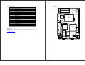
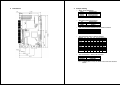
PCISA-C3/EDEN
VIA® Processor CPU Board with 10/100Mb LAN & VGA
March 30, 2006
Quick Startup Reference
Version 2.0
Specifications
VIA® C3 EBGA packing (FSB: Supports 100/133MHz)
Bus:
DMA channels:
Interrupt levels: 15
Chipset: VIA® VT8601A (Integrated 2D / 3D graphics accelerator.) & VT82C686B
RAM memory:
- One 168-pin DIMM sockets.
- Maximum memory is 512MB.
Ultra ATA/33/66/100 IDE Interface: Two PCI Enhance IDE hard drives. The
south bridge VT82C686B supports Ultra ATA/33/66/100 IDE interface.
Floppy disk drive interface: Supports 2.88 MB, 1.44MB, 1.2MB, 720KB, or
360KB floppy disk drive.
Two high speed serial ports: NS16C550 compatible UART’ s
Bi-directional parallel port: IEEE1284 compatible
IrDA port: Supports Serial Infrared (SIR) and Amplitude Shift Keyed IR (ASKIR)
interface.
USB port: Equipped with four USB ports for future expansion.
Intel 82559 or REALTEK RTL8100 Fast Ethernet Multifunction PCI
Controller:
- IEEE 802.3u Auto-Negotiation support for 10BASE-T/100BASE-TX
standard.
- Fast back-to-back transmission support with minimum interface
spacing.
- Connected to your LAN via RJ45 connector.
Keyboard connector & PS/2 Mouse Port on-board
PICMG Bus (Support PCI Master x 4)
7
Power Consumption: +5VSB @ 180mA, +5V @ 3.8A, +12V @ 170mA
(C3-800MHz with 512MB SDRAM x 2, Windows2000)
Operating Temperature: 0 ° ~ 55° C (CPU needs Cooler)
Package Contents
Before you begin installing the product, please check the following materials
are included in the package:
PCISA-C3/EDEN SERIES Single Board Computer x1
IDE HDD Cable x 1
FDD Cable x 1
RS-232/Print Cable x 1
Y Cable x 1
Audio Cable x 1
RS-422/485 Cable x 1
Companion CD (for user manual, drivers…etc.) x 1
Quick Startup Reference x 1
If any of these items are missing or damaged, contact your distributor or sales
representative immediately.
Connection
LABEL
IDE1
CN2
CN10
IDE2
FDD1
JP3
U10
BIOS
C3
CPU
DIMM1
CN4
CN5
JBAT1
FDC CONNECTOR
IDE Interface Connector
Parallel Port Connector
4 ports USB Connector
2 Pin Power Button Switch
Serial Port 10-pin Connector
6-pin DIN Keyboard/Mouse Connector
5-pin External Keyboard Connector
IrDA connector
CPU / SYS. Fan Connector
15-pin Female Connector
4-pin Connector
External Switches and Indicators
PS-ON Connector
LAN1 RJ45 Connector (10/100)
External LED Connector
Compact Flash Storage Card Socket pin assignment
Audio Connector
Audio Connector
RS422/485 Connectors
JFAN2
FDD1
IDE1 / IDE2
PRN1
USB1 /USB2
CN5
COM1 / COM2
P2
CN3
J1
JFAN1 / JFAN2
P3
CN10
CN4
CN9
P1
CN1
CN2
CN8
CD_IN1
CN13
Layout
FUNCTION
BAT1
CN9 JP5
J1
JFAN1
PSON
U3
U2
PRN1
Support
For any questions regarding the product or documentation, please email us at:
JP2
[email protected].
U14
CD_IN1
CN8
P3
COM2
COM1
P1
USB2
P2
CN1
CN13
CN3
USB1
U21
DOC
Dimensions
Jumper Setting
JBAT1: Clear CMOS Setup
JBAT1
DESCRIPTION
1-2
(default)*
Short 2-3
Keep CMOS Setup
(Normal Operation)
Clear CMOS Setup
JP3: Master/Slave Mode Setting
JP3
DESCRIPTION
SHORT *
OPEN
MASTER
SLAVE
CN4 (2-4): Enabled/Disabled Onboard Buzzer Function
2-4
DESCRIPTION
SHORT *
OPEN
Enabled
Disabled
JP2: DiskOnChip Memory Address Settings
ADDRESS
CC000
1-2
3-4
5-6
7-8
9-10 11-12 13-14
OPEN OPEN CLOSE OPEN OPEN CLOSE CLOSE
CE000
OPEN OPEN OPEN CLOSE OPEN CLOSE CLOSE
D0000
CLOSE OPEN OPEN OPEN CLOSE OPEN CLOSE
D2000
OPEN CLOSE OPEN OPEN CLOSE OPEN CLOSE
D4000
OPEN OPEN CLOSE OPEN CLOSE OPEN CLOSE
D6000
OPEN OPEN OPEN CLOSE CLOSE OPEN CLOSE
D8000
CLOSE OPEN OPEN OPEN OPEN OPEN CLOSE
DA000
OPEN CLOSE OPEN OPEN OPEN OPEN CLOSE
DC000
OPEN OPEN CLOSE OPEN OPEN OPEN CLOSE
DE000
OPEN OPEN OPEN CLOSE OPEN OPEN CLOSE
JP5: COM2 RS232 or RS422/485 Selection
JP5
DESCRIPTION
1-2 Short
2-3 Short
RS232
RS422/485
Caution: If RS422/485 is in use, the COM2 on the main board would be
disable.