1
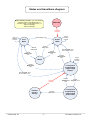
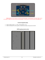
FlexControl 14
User’s manual
Firmware v0.2
www.kae-systems.com
‘FlexControl 14’
-1-
Firmware version 0.2
What’s this?
‘FlexControl 14’ is an universal multi-purpose MIDI device. It provides 14 digital buffered
outputs, controllable simultaneously by: 14 on-board digital/analog inputs, MIDI messages or another
‘FlexControl 14’ device. Also, it can transmit up to 3 messages at once at activation of any digital input,
and send Control Change messages on change of analog inputs.
Hardware features (board revision A)
•
•
•
•
•
•
•
•
•
•
•
•
•
14 high-current open-collector digital outputs for relays / LEDs / servo motors
14 digital inputs (pulled up) for buttons or switches / up to 11 analog inputs for potentiometers
All digital inputs and outputs go out on standard 2,54mm male connectors
1 ‘MIDI In’ DIN5 connector
1 ‘MIDI Out/Thru’ DIN5 connector
Semi-transparent illuminated button for MIDI presets programming
RJ-45 jack for connecting another ‘FlexControl 14’ remote control board over straight-through
Ethernet cable.
Phantom power with configurable polarity available on pins 1 and 3 of the ‘MIDI In’ jack
2.5mm DC power jack (with center positive pin).
2-pin DC power connector
Reverse polarity protection
Specially designed for panel mounting
Non-volatile memory to store user configuration and presets
‘FlexControl 14’
-2-
Firmware version 0.2
How does it work?
‘FlexControl 14’ comes with 3 pre-programmed firmware profiles (applications), which
implement specific behavior.
Beside application-specific behavior, all firmware profiles share following common features:
Configurable activation edges of digital inputs. The choice is between falling and both falling and
rising edges. This allows both retentive and non-retentive switches to be attached to the inputs.
• Individually configurable role of each output (PWM or simple digital).
• Individually configurable period and duty cycle for each PWM output
•
Following features are available for all profiles, except for ‘Remote’:
• Individually configurable role of each input pin (analog or digital)
• Individually configurable transformation type for each analog input. The input analog value will
be (optionally) transformed and then sent in MIDI CC message and (optionally) to PWM output
with same number.
You can choose between following transformations: exponent, logarithmic and Gaussian (‘Scurve’).
• Configurable polarity of the outputs (normally ‘off’ or normally ‘on’), also applicable for PWM
outputs.
• Configurable mutual exclusive digital outputs (i.e. “mutex”). In a mutex group, there can be only
one active output. There can be mutex and non-mutex outputs working in parallel.
• Configurable delay at startup
• Configurable reception (Rx) MIDI channel (1-16 or all)
• Configurable transmission (Tx) MIDI channel (1-16). Tx channel is valid for all transmitted
messages.
• Configurable Rx MIDI controller for output #1. The rest of the outputs have consecutive
increasing numbers.
• Configurable Tx MIDI controller for analog input #1. The rest of the inputs have consecutive
increasing numbers.
• Configurable MIDI presets (retrievable on Rx PC messages).
• Configurable Tx messages. Up to 3 messages can be sent at once on each activation of a digital
input (either local or remote). For messages with 2 data bytes, the value of second data byte is
also configurable and may follow the state of the digital output with same number. All message
types, except SysEx, can be transmitted.
• MIDI Thru – every byte, received on MIDI In will be immediately sent to MIDI Out. However, if
there is configured at least one analog channel or Tx message, MIDI Thru will not be available.
Each profile requires specific hardware wiring (explained in profile’s description).
Firmware profiles are configured by special Windows® application ‘FlexControl configurator’.
Analog inputs
Up to 11 of the inputs can be configured as analog type, thus allowing potentiometers to be
attached to them. The result of analog-to-digital conversion is a 7-bit value which is (optionally)
transformed (see charts below) and sent in MIDI CC message and (optionally) – to PWM output with
same number (as input pin). Messages are sent only on change of the measured value.
However, You should remove corresponding pull-up resistors, located on the bottom side of
the board (rev.A), according to table below. We recommend linear potentiometers between 500 Ω and
‘FlexControl 14’
-3-
Firmware version 0.2
5 kΩ. Also, we highly recommend a 100 ÷ 200nF capacitor to be soldered between the analog pin and
GND as close as possible to the MCU, like shown on the connection diagram below:
Input #
1
2
3
4
5
6
7
8
9
10
11
12
13
14
Pull-up
resistor
R21
R18
R17
R15
R14
R13
R11
R10
R9
R8
R7
R6
R5
R4
Note
Can’t be analog
Can’t be analog
Can’t be analog
Each analog input have auto-range feature, allowing the attached potentiometer to operate in
limited range and yet to give full-range 7-bit values. The min-max ranges can be reset anytime with the
help of ‘FlexControl Configurator’ tool.
Most suitable sources of stabilized 5V supply
for potentiometers are shown on the pictures on
the left and right.
Transformation charts
Exponential
Logarithmic
Gaussian
* Range of values for both axes: [0..127]
* Input values are on horizontal axes
* The charts represent actual values.
‘FlexControl 14’
-4-
Firmware version 0.2
Profile “Amp control”
Designed to control guitar/bass amplifiers.
Firmware operation
• Each digital input can control only an digital output with the same number (In 1 -> Out 1; In 2 ->
Out 2 and etc.).
• All the 14 digital outputs have latching action (see below for the exception).
• One of the digital outputs can be assigned (optionally) to act as a pulse output, which is
activated simultaneously with any other digital output.
• Every digital output (except the pulse one) can be switched on and off individually by a MIDI
‘Control change’ message.
• Some (or all) outputs can be configured in mutual exclusive group (“mutex”). In addition, the
state of all non-mutex outputs can be memorized and subsequently restored on activation of a
mutex output.
• Non-mutex outputs toggle on each activation.
• All outputs (except the pulse one) can be switched at once by a MIDI ‘Program change’ message.
• A MIDI preset can be programmed by starting a MIDI preset programming sequence.
Wiring diagram
Profile “Looper”
Designed to control effect switching systems (a.k.a “loopers”) for musicians. The idea is the
musician to switch numerous effect pedals at once with a single button/switch.
‘FlexControl 14’
-5-
Firmware version 0.2
Firmware operation
The user has 14 digital inputs, 14 relay outputs and 14 indication outputs. The relay outputs control
the effect pedals (on/off), while indication outputs show additional information depending on the work
mode. The relay outputs can be loaded at once by a ‘preset’. There are 14 local and 128 MIDI presets.
Those preset groups are independent from each other and are stored in separate non-volatile memory
locations. The local presets can be recalled only by the digital inputs, while the MIDI presets can be
recalled only by MIDI ‘Program change’ messages.
There are 3 modes of operation:
• ‘Preset’ – the user loads pre-programmed local presets into relay outputs.
• ‘Free’ – relay outputs can be freely turned on or off
• ‘Local preset programming’ – the user can define the local presets that’ll be used in ‘Preset’
mode.
One ‘FlexControl 14’ board can output only first 7 relay outputs and first 7 indication outputs; the
upper outputs are supplied by another ‘FlexControl 14’ board, working with profile ‘Remote’.
A MIDI preset can be programmed by starting a MIDI preset programming sequence, but only from
modes ‘Preset’ or ‘Free’.
Wiring diagram
‘FlexControl 14’
-6-
Firmware version 0.2
States and transitions diagram
Output activation requests – one of the following:
- Activation edges on local digital inputs 1-7
- Activation edges on remote digital inputs 1-14
- MIDI PC messages
- MIDI CC messages
Powerup
Automatic
transition
Output
activation
requests
Activate “Free” input
‘Preset’
Mode
‘Free’
Mode
Output
activation
requests
Activate
relay inputs
Activate
relay inputs
Activate
“Mute/Cancel”
input
Activate
“Mute/Cancel”
input
Hold “Program” input
low for at least 3 sec.
Activate
“Mute/Cancel”
input
MUTE
Activate
“Mute/Cancel”
input
Output
activation
requests
Local preset
programming,
stage ‘Setup
outputs’
Hold “Program” input
low for at least 3 sec.
Automatic
transition
Indicate
preset’s
storage
‘FlexControl 14’
Activate
relay inputs
-7-
Activate
Activate
“Mute/Cancel”
“Program” input
input
Local preset
programming,
stage ‘Setup
preset index’
Firmware version 0.2
Action table
Stimulus source
Stimulus type
Work mode
Preset
Relay inputs
Activation edge
Free
Local preset programming,
stage 'Setup outputs'
Local input 12
'Local
programming'
Active level
(Hold for at least
3 seconds to
enter 'Local
preset
programming'
mode)
Preset
Free
Local preset programming,
stage 'Setup outputs'
Activation edge
Local preset programming,
stage 'Setup preset index'
Local input 13
'Free'
Local input 14
'Mute/Cancel'
Activation edge
Activation edge
Preset
Free
All other
Preset
Free
Local preset programming
Mute
MIDI Program
change
message
MIDI Controller
change
message
‘FlexControl 14’
-
value > 63
value < 64
Preset
Free
Preset
Free
Local preset programming
-8-
Action
Input 1 loads preset #1, Input 2 loads
preset #2 etc.
Relay outputs show the currently active
local preset.
Indication outputs show the index of
currently active local preset.
Relay outputs:
- Mutex outputs: requested output is on,
others - off
- Non-mutex outputs: toggle
Indication outputs: all off
Relay outputs:
- Mutex outputs: requested output is on,
others - off
- Non-mutex outputs: toggle
Indication outputs: all on
Enter stage 'Setup outputs'
Indication outputs: all on.
Go to stage 'Setup preset index'
Indication outputs starts to toggle with fast
rate.
The indication outputs show the index of
currently programmed preset with 3-time
blink.
Go back to stage 'Setup outputs'
Go to "Free" mode
Go to "Normal" mode.
No effect.
Turn all relay outputs off immediately
If in stage "Setup outputs": return to
normal or free mode
If in stage "Setup preset number": return
to stage "Setup outputs"
Restore the previous state of relay outputs
Load a MIDI preset to relay outputs
Only relay outputs: turn on specific channel
Only relay non-mutex outputs: turn off
specific channel
Firmware version 0.2
Profile “Remote”
Designed as slave extension or remote control when working together with another master
‘FlexControl 14’ board. Both master and slave boards should be connected with a straight-through
Ethernet cable (same pinout on both ends). The profile doesn’t react on MIDI PC and CC messages.
When used with master ‘Amp control’ board, it acts only as remote control:
- ‘Remote’ inputs and ‘Amp control’ digital inputs work in parallel.
- ‘Remote’ outputs copy the state of ‘Amp control’ outputs.
When used with master ‘Looper’ board, there are 2 scenarios:
• The ‘Looper’ interprets ‘Remote’ as remote control.
‘Remote’ device provide all 14 digital inputs. ‘Remote’s inputs 1-7 and ‘Amp control’s inputs 1-7
work in parallel.
All ‘Remote’s outputs copy the state of ‘Looper’s outputs.
• The ‘Looper’ interprets ‘Remote’ as extension.
In this case ‘Remote’s outputs 1-7 will output relay outputs 8-14, and ‘Remote’s outputs 8-14 will
output indication outputs 8-14.
Wiring diagram
The wiring is the same as the wiring of the master board, except of the power jack and internal
power pins.
Important: The ‘Remote’ board should be powered only from the master board through the
Ethernet cable! Don’t connect any power supply to the remote board - neither to the DC power jack nor
the internal DC power connector!
MIDI preset programming sequence
(Only for firmware profiles ‘Amp Control’ and ‘Looper’)
1.
2.
3.
4.
5.
6.
7.
8.
Power the device on.
Connect your MIDI controller’s MIDI output to the ‘FlexControl’s ‘MIDI In’ jack.
Press and hold the illuminated button until it starts to blink with a short pulse.
Configure the outputs you want in a preset (by on-board digital inputs / remote / MIDI CC
message)
Send a MIDI PC message from your MIDI controller. The illuminated button will start to blink
rapidly.
Press the button shortly to confirm the preset. It will light on for a while and after that will revert
automatically to short pulse blinking.
Repeat steps 4 to 6 if necessary
To exit the programming sequence, press and hold the illuminated button until it light off or
leave the board idle for 100 seconds.
‘FlexControl 14’
-9-
Firmware version 0.2
‘FlexControl configurator’ utility
All important parameters of the firmware profiles can be configured only with few mouse clicks
with the help of ‘FlexControl configurator’. It’s a small .NET GUI application for Microsoft® Windows OS.
Following prerequisites should be fulfilled to run the application:
• Your OS version should be at least ‘Windows XP SP3’
• .NET 4.0 or .NET 4.5 framework installed on your computer. Installation requires administrator
privileges.
• A sound card with MIDI port or USB-MIDI cable connected to your computer.
Connect the MIDI Out jack of your device to the MIDI In jack of ‘FlexControl 14’ board and launch
the application.
First, you should select the active firmware profile, by clicking menu ‘Firmware profile’. Then
adjust the rest of parameters you need.
You can save the configuration you’ve made to a file.
Finally, hit the button ‘Write to device’ and wait for transfer to complete. The new configuration
will take effect at next power up.
Changing the firmware
1.
2.
3.
4.
5.
Go to www.kae-systems.com and navigate to ‘FlexControl 14’ page.
Download the firmware version you want. Firmware files have *.bin extension.
Download ‘FlexControl configurator’ with the same version as the firmware file.
Bring back to mind instructions from previous chapter ‘FlexControl configurator’ utility.
Open ‘FlexControl configurator’ and click menu ‘Update firmware’. A new dialog window will pop, so
You can enter a path to the downloaded firmware file. Click button ‘Go!’ and wait to complete.
Troubleshooting
During the update process, the illuminated button will blink with fast rate. If download has been
successful, the button will light on for 2 seconds, then light off; otherwise, it will light on constantly and
remain it this state.
If download fails or hasn’t been started at all, it could be because of:
- You didn’t connect the MIDI cable to ‘FlexControl 14’
- The firmware is intended for other device
Then you should correct preconditions and try again.
Supplying phantom power to pins 1 and 3 of the MIDI In jack
Some MIDI devices can be powered through spare pins 1 and 3 of their MIDI Out jacks.
‘FlexControl 14’ is ready to complement this feature by bridging its power sources (DC power jack or DC
internal connector) to 4 jumper pads on its bottom side. Depending on the device you want to power,
you’ll need to shorten jumpers J1+ and J1- or J2+ and J2-, as shown on the picture below:
‘FlexControl 14’
- 10 -
Firmware version 0.2
Please note: Do not shorten any of J1x and J2x jumpers simultaneously! That will short circuit
your power supply and almost certainly will damage it; ‘FlexControl 14’ will be certainly damaged too!
Electrical specifications
•
•
Supply voltage range: 7,5 – 25V, recommended 9 - 15V.
Power consumption: 20 mA @ 12V; no loads connected; all outputs off; LED off.
MIDI implementation chart
Message type
Note off
Note on
Polyphonic aftertouch
Control change
Program change
Channel aftertouch
Pitch wheel
Quarter frame (MTC)
Song pointer
Song select
Tune request
Timing clock
Start
Continue
Stop
Active Sensing
Reset
‘FlexControl 14’
8x
9x
Ax
Bx
Cx
Dx
Ex
F1
F2
F3
F6
F8
FA
FB
FC
FE
FF
- 11 -
Can receive
Yes
Yes
-
Can send
Yes
Yes
Yes
Yes
Yes
Yes
Yes
Yes
Yes
Yes
Yes
Yes
Yes
Yes
Yes
Yes
Yes
Firmware version 0.2
Straight-through Ethernet cable pinout
Mechanical drawing
All dimensions in millimeters.
‘FlexControl 14’
- 12 -
Firmware version 0.2