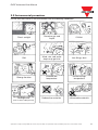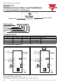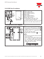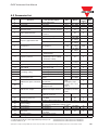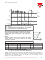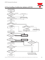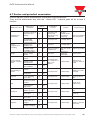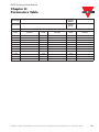
1
CARLO GAVAZZI
Automation
Components
VariFlex2
RVDF Series
Advanced User Manual
110V
Class 1ph
220V
Class 1ph
Class 3ph
440V
Class 3ph
0.20~0.75kW
0.25~1.0HP
0.20~2.2kW
0.25~3.0HP
1.50~2.2kW
2.0~3.0HP
0.75~2.2kW
1.0~3.0HP
RVDF Advanced User Manual
General Information
The manufacturer accepts no liability for any consequences resulting from inappropriate,
negligent or incorrect installation or adjustment of the optional parameters of the equipment
or from mismatching the variable speed drive with the motor.
The contents of this guide are believed to be correct at the time of printing. In the interests of
commitment to a policy of continuous development and improvement, the manufacturer
reserves the right to change the specification of the product or its performance, or the
content of the guide without notice.
All rights reserved. No parts of this guide may be reproduced or transmitted in any form or by
any means, electrical or mechanical including, photocopying, recording or by an information
storage or retrieval system, without permission in writing from the publisher.
Environmental Statement
The electronic variable speed drives have the potential to save energy and (through increased
machine/process efficiency) reduce raw material consumption and scrap throughout their
long working lifetime. In typical applications, these positive environmental effects far
outweigh the negative impacts of product manufacture and end-of-life disposal.
Nevertheless, when the products eventually reach the end of their useful life, they can very
easily be dismantled into their major component parts for efficient recycling. Many parts snap
together and can be separated without the use of tools, while other parts are secured with
conventional screws.
Virtually all parts of the product are suitable for recycling.
Product packaging is of good quality and can be re-used. All the products come in strong
cardboard cartons which themselves have a high recycled fibre content. If not re-used, these
containers can be recycled. Polythene, used on the protective film and bags from wrapping
product, can be recycled in the same way. Carlo Gavazzi packaging strategy favours easily
recyclable materials of low environmental impact, and regular reviews identify opportunities
for improvement.
When preparing to recycle or dispose of any product or packaging, please observe local
legislation and best practice.
© Copyright - Carlo Gavazzi – All rights reserved - Revision. R00
Specifications are subject to change without notice. Pictures are just an example. For special features and/or customization, please ask to our sales network. 121109
RVDF Advanced User Manual
CONTENTS
Chapter 0: Preface . . . . . . . . . . . . . . . . . . . . . . . . . . . . . . . . . . . . . . . . . . . . . . . . . . . . . . . 4
0.1 Preface . . . . . . . . . . . . . . . . . . . . . . . . . . . . . . . . . . . . . . . . . . . . . . . . . . . . . . . . . . . . 4
0.2 Examination before installation . . . . . . . . . . . . . . . . . . . . . . . . . . . . . . . . . . . . . . . . . . 4
Chapter 1: Safety Precaution . . . . . . . . . . . . . . . . . . . . . . . . . . . . . . . . . . . . . . . . . . . . . . . 5
1.1 Operation Precaution . . . . . . . . . . . . . . . . . . . . . . . . . . . . . . . . . . . . . . . . . . . . . . . . . 5
1.1.1 Before power ON . . . . . . . . . . . . . . . . . . . . . . . . . . . . . . . . . . . . . . . . . . . . . . . . . 5
1.1.2 When power is applied . . . . . . . . . . . . . . . . . . . . . . . . . . . . . . . . . . . . . . . . . . . . 6
1.1.3 Under operation . . . . . . . . . . . . . . . . . . . . . . . . . . . . . . . . . . . . . . . . . . . . . . . . . . 6
1.1.4 When performing an examination or maintenance . . . . . . . . . . . . . . . . . . . . . . . 7
Chapter 2: Ambient Environment and Installation . . . . . . . . . . . . . . . . . . . . . . . . . . . . . . 8
2.1 Environment . . . . . . . . . . . . . . . . . . . . . . . . . . . . . . . . . . . . . . . . . . . . . . . . . . . . . . . . 8
2.2 Environment precautions . . . . . . . . . . . . . . . . . . . . . . . . . . . . . . . . . . . . . . . . . . . . . . 9
Chapter 3: Hardware Instructions and Installation . . . . . . . . . . . . . . . . . . . . . . . . . . . . 10
3.1 Sample Model No. Identification . . . . . . . . . . . . . . . . . . . . . . . . . . . . . . . . . . . . . . . 10
3.2 Type Selection . . . . . . . . . . . . . . . . . . . . . . . . . . . . . . . . . . . . . . . . . . . . . . . . . . . . . . 10
3.3 Connection Diagrams . . . . . . . . . . . . . . . . . . . . . . . . . . . . . . . . . . . . . . . . . . . . . . . . 10
3.4 Specification . . . . . . . . . . . . . . . . . . . . . . . . . . . . . . . . . . . . . . . . . . . . . . . . . . . . . . . 11
3.4.1 Products Individual Specification . . . . . . . . . . . . . . . . . . . . . . . . . . . . . . . . . . . 11
3.4.2 General Specifications . . . . . . . . . . . . . . . . . . . . . . . . . . . . . . . . . . . . . . . . . . . . 12
3.5 Wiring Specification and Suitable Optionals . . . . . . . . . . . . . . . . . . . . . . . . . . . . . . 13
3.6 Description of Inverter Terminals . . . . . . . . . . . . . . . . . . . . . . . . . . . . . . . . . . . . . . . 17
3.6.1 Descriptionsof Main Circuit Terminals . . . . . . . . . . . . . . . . . . . . . . . . . . . . . . . . 17
3.6.2 Control Circuitry Terminal Block (TM2) Description . . . . . . . . . . . . . . . . . . . . . 17
3.7 RVDF - IP20 Type . . . . . . . . . . . . . . . . . . . . . . . . . . . . . . . . . . . . . . . . . . . . . . . . . . . 18
3.7.1 DIN-Rail mounting diagram . . . . . . . . . . . . . . . . . . . . . . . . . . . . . . . . . . . . . . . . 18
3.7.2 Additional DIN-Rail Installation . . . . . . . . . . . . . . . . . . . . . . . . . . . . . . . . . . . . . 18
3.7.3 RVDF IP20 Type Dimensions . . . . . . . . . . . . . . . . . . . . . . . . . . . . . . . . . . . . . . . 19
3.8 RVDF - IP65 Type . . . . . . . . . . . . . . . . . . . . . . . . . . . . . . . . . . . . . . . . . . . . . . . . . . . 20
3.8.1 RVDF Size A Installation . . . . . . . . . . . . . . . . . . . . . . . . . . . . . . . . . . . . . . . . . . 20
3.8.2 RVDF Size A Circuit Diagram . . . . . . . . . . . . . . . . . . . . . . . . . . . . . . . . . . . . . . 20
3.8.3 RVDF Size A Connections . . . . . . . . . . . . . . . . . . . . . . . . . . . . . . . . . . . . . . . . . 20
3.8.4 RVDF Size A EMC mounting . . . . . . . . . . . . . . . . . . . . . . . . . . . . . . . . . . . . . . . 20
3.8.5 RVDF Size B Installation . . . . . . . . . . . . . . . . . . . . . . . . . . . . . . . . . . . . . . . . . . 21
3.8.6 RVDF Size B Circuit Diagram . . . . . . . . . . . . . . . . . . . . . . . . . . . . . . . . . . . . . . 21
3.8.7 RVDF Size B Connections . . . . . . . . . . . . . . . . . . . . . . . . . . . . . . . . . . . . . . . . . 22
3.8.8 RVDF Size B EMC mounting . . . . . . . . . . . . . . . . . . . . . . . . . . . . . . . . . . . . . . . 22
3.8.9 RVDF IP65 Type Dimensions . . . . . . . . . . . . . . . . . . . . . . . . . . . . . . . . . . . . . . . 23
Chapter 4: Software Index . . . . . . . . . . . . . . . . . . . . . . . . . . . . . . . . . . . . . . . . . . . . . . . . 24
4.1 Keypad operating instructions . . . . . . . . . . . . . . . . . . . . . . . . . . . . . . . . . . . . . . . . . 24
4.2 Brief Keypad Operating Flowchart . . . . . . . . . . . . . . . . . . . . . . . . . . . . . . . . . . . . . . 24
4.3 Parameter List . . . . . . . . . . . . . . . . . . . . . . . . . . . . . . . . . . . . . . . . . . . . . . . . . . . . . . 25
4.4 Parameter function description . . . . . . . . . . . . . . . . . . . . . . . . . . . . . . . . . . . . . . . . 26
2
Specifications are subject to change without notice. Pictures are just an example. For special features and/or customization, please ask to our sales network. 121109
RVDF Advanced User Manual
Chapter 5: Troubleshooting . . . . . . . . . . . . . . . . . . . . . . . . . . . . . . . . . . . . . . . . . . . . . . .
5.1 Manual Reset Inoperative Malfunctions . . . . . . . . . . . . . . . . . . . . . . . . . . . . . . . . . .
5.2 Manual Reset Operative Malfunctions (Auto-reset inoperative) . . . . . . . . . . . . . . . .
5.3 Manual Reset and Auto-Reset Operative Malfunctions . . . . . . . . . . . . . . . . . . . . . .
5.4 Special Condition Description . . . . . . . . . . . . . . . . . . . . . . . . . . . . . . . . . . . . . . . . .
5.5 Keypad Operation Error Instruction . . . . . . . . . . . . . . . . . . . . . . . . . . . . . . . . . . . . .
5.6 General Multifunction Examination Method . . . . . . . . . . . . . . . . . . . . . . . . . . . . . . .
Chapter 6: Troubleshooting Procedures . . . . . . . . . . . . . . . . . . . . . . . . . . . . . . . . . . . . .
6.1 General procedure in case of malfunction . . . . . . . . . . . . . . . . . . . . . . . . . . . . . . . .
6.2 Error handling of malfunction indication of OC.OL . . . . . . . . . . . . . . . . . . . . . . . . .
6.3 Error handling of malfunction indication of OV.LV . . . . . . . . . . . . . . . . . . . . . . . . . .
6.4 Motor inoperative . . . . . . . . . . . . . . . . . . . . . . . . . . . . . . . . . . . . . . . . . . . . . . . . . . .
6.5 Motor over-heat . . . . . . . . . . . . . . . . . . . . . . . . . . . . . . . . . . . . . . . . . . . . . . . . . . . .
6.6 Disturbing motor operation . . . . . . . . . . . . . . . . . . . . . . . . . . . . . . . . . . . . . . . . . . . .
6.7 Routine and periodical examination . . . . . . . . . . . . . . . . . . . . . . . . . . . . . . . . . . . . .
6.8 Maintenance and Examination . . . . . . . . . . . . . . . . . . . . . . . . . . . . . . . . . . . . . . . . .
6.9 Voltage Current Measurement . . . . . . . . . . . . . . . . . . . . . . . . . . . . . . . . . . . . . . . . .
Chapter 7: Peripherals . . . . . . . . . . . . . . . . . . . . . . . . . . . . . . . . . . . . . . . . . . . . . . . . . . .
7.1 EMI Filter Specification . . . . . . . . . . . . . . . . . . . . . . . . . . . . . . . . . . . . . . . . . . . . . . .
7.2 Specification Input Reactor and Braking Built-In Features . . . . . . . . . . . . . . . . . . .
7.3 Specification of Braking Resistor . . . . . . . . . . . . . . . . . . . . . . . . . . . . . . . . . . . . . . .
Chapter 8: Parameters Table . . . . . . . . . . . . . . . . . . . . . . . . . . . . . . . . . . . . . . . . . . . . . .
Specifications are subject to change without notice. Pictures are just an example. For special features and/or customization, please ask to our sales network. 121109
36
36
36
36
37
37
38
39
39
41
42
43
44
44
45
46
47
48
48
48
48
49
3
RVDF Advanced User Manual
Chapter 0:
Preface
0.1 Preface
To fully employ all functions of this AC Drive, and to ensure the safety for its users, please
read through this operations manual in detail. Should you have any further questions, please
feel free to contact your local distributor or regional representative.
¤ Please use Precaution with this product
The AC Drive is a power electronic device. For safety reasons, please read carefully those
paragraphs with “WARNING” or “CAUTION” symbols. They are important safety precautions to
be aware of while transporting, installation, operating or examining the AC drive. Please follow
these precautions to ensure your safety.
Danger
Caution
Personnel injury may be resulted by improper operation.
The AC Drive or mechanical system may be damaged by improper
operation.
Danger
• Do not touch the PCB or components on the PCB right after turning off the power before
the charging indicator went off.
• Do not attempt to wire circuitry while power is on. Do not attempt to examine the
components and signals on the PCB while the inverter operating.
• Do not attempt to disassemble or modify internal circuitry, wiring, or components of the inverter.
• The grounding terminal of the inverter must be grounded properly with 200V class type III standard.
This is a product of the restricted sales distribution class according to EN61800-3.
In a domestic environment this product may cause radio interference in which case the user
may be required to take adequate measures.
Caution
• Do not attempt to perform dielectric strength test to internal components of the inverter.
There are sensitive semiconductor-devices vulnerable to high voltage in the inverter.
• Do not connect the output terminals: T1 (U), T2 (V), and T3 (W) to AC power input
• The CMOS IC on the primary PCB of the inverter is vulnerable to static electrical charges.
Do not contact the primary PCB of the inverter.
0.2 Examination before installation
Every inverter has been fully tested and examined before shipment. Please carry out the
following examination procedures after unpacking your AC inverter.
• Check to see if the model number of the AC inverter matches the model number of the AC
inverter that you ordered.
• Check to see whether any damage occurred to the AC inverter during shipment. Do not
connect the AC inverter to the power supply if there is any sign of damage.
Report this to a regional sale representative if you find any abnormal condition as mentioned above.
4
Specifications are subject to change without notice. Pictures are just an example. For special features and/or customization, please ask to our sales network. 121109
RVDF Advanced User Manual
Chapter 1:
Safety Precautions
1.1 Operation Precaution
1.1.1 Before Power ON
Caution
Choose the appropriate power source with correct voltage settings for the input voltage
specification of the AC inverter.
Danger
Special care must be taken while wiring the primary circuitry panel. The L1 and L2 terminal must
be connected to the input power source and must not be mistakenly connected to T1, T2 or T3
output terminals. This may damage the inverter when the power is turned on.
Caution
• Do not attempt to transport the inverter by the front of the cover. Securely hold the
inverter by the heat-sink mounting chassis to prevent the inverter from falling, this may
cause personnel injury or damage to the inverter itself.
• Install the inverter onto a firm metal base plate or another non-flammable type material.
Do not install the inverter onto or nearby any flammable material.
• An additional cooling fan may need to be installed if several inverters are installed into one
control panel. The inside temperature inside an enclosed panel should be below 40
degrees to avoid overheating.
• Turn off the power supply before proceeding to remove or perform any work on any panel.
Carry out installation procedures according to instructions given in order to avoid a
situation resulting in an operational malfunction.
• Suitable for use on a circuit capable of delivering not more than 5000 RMS symmetrical
amperes. 240 Volts maximum.
• This product is not provided with over speed protection.
• Only intended for use in a pollution degree 2 macro environment or equivalent
Specifications are subject to change without notice. Pictures are just an example. For special features and/or customization, please ask to our sales network. 121109
5
RVDF Advanced User Manual
1.1.2 When power is applied
Warning
• Do not attempt to install or remove input or output connectors of inverter when the power
supply is turned on. Otherwise, the inverter may be damaged due to the surge peak
caused by the insertion or removal of power.
• When momentary power loss is longer than 2 seconds (the large of horse power, the
longer of time), the inverter does not have enough storage power to control the circuit;
Therefore, when power is regenerated, the operation of the inverter is based on the setup
of F_10 and the condition of external switch, this is considered to be restart in the
following paragraphs.
When the momentary power loss is short, the inverter still has enough storage power to
control the circuit; therefore, when power is regenerated, the inverter will automatically
start operation again depends on the setup of F_23.
• When restart the inverter, the operation of the inverter is based on the setup of F_10 and
the condition of external switch (FWD/REV button). Attention: the restart operation is
irrelevant with F_23/F_24.
(1) When F_10=0, the inverter will not start after restart.
(2) When F_10=1 and the external switch (FWD/REV button) is OFF, the inverter will not
start after restart.
(3) When F_10=1 and the external switch (FWD/REV button) is ON, the inverter will start
automatically after restart. Attention: Base on safety reason, please turn off the external
switch (FWD/REV button) after power loss to avoid possible damage to the machine and
the human body after sudden regeneration of power.
1.1.3 Under Operation
Warning
Do not use a separate device to switch ON or OFF motor during operation. Otherwise, the
inverter may experience an over-current breakdown.
Warning
• Do not remove the front cover of the inverter when the power is ON to avoid personnel
injury caused by electrical shock.
• When the automatic restart function is enabled, the motor and machinery will be restarted
automatically.
Caution
• Do not touch the heat-sink base during operation.
• The inverter can be easily operated from a low-speed to high-speed range. Please
reconfirm the operating range of motor and the machinery you are controlling.
• Do not examining the signals on the PCB of the inverter when it is under operation.
• All inverters are properly adjusted and set before delivery.
6
Specifications are subject to change without notice. Pictures are just an example. For special features and/or customization, please ask to our sales network. 121109
RVDF Advanced User Manual
Caution
Do not proceed with disassemble or examination procedure before ensuring that the power
is off and the Power LED extinguished.
1.1.4 When performing an examination or maintenance
Caution
Inverter environment should be within temp: -10°C ~ +40°C, humidity under 95% RH without
condensing.
Caution
After the removal of shield sticker, the environment temperature should be within -10°C ~
+50°C and humidity under 95% RH without condensing. Besides, the inverter should be free
from water dripping or metal dust.
Specifications are subject to change without notice. Pictures are just an example. For special features and/or customization, please ask to our sales network. 121109
7
RVDF Advanced User Manual
Chapter 2:
Ambient Environment and Installation
2.1 Environment
The installation site of the inverter is very important. It relates directly to the functionality and
the life span of your inverter. Please carefully choose the installation site to meet the following
requirements:
• Mount the unit vertically
• Environment temperature: -10°C ~ +40°C (without shield sticker: -10°C ~ +50°C)
• Avoid placing close to any heating equipment
• Avoid water dripping or humid environment
• Avoid direct sunlight
• Avoid oil or salty corrosive gas
• Avoid contacting corrosive liquid or gas
• Prevent foreign dusts, flocks, or metal scraps from entering interior
• Avoid electric-magnetic interference (soldering or power machinery)
• Avoid vibration, if vibration cannot be avoided, an anti-rattle mounting device should be
installed to reduce vibration.
• If the inverter is installed in an enclosed control panel, please remove the shield sticker
located at the top of the inverter. This will allow additional airflow and cooling.
Air exchanging fan
Air exchanging fan
Inside the power
distributor
Inside the
power
distributor
(Correct configuration)
(Incorrect configuration)
Inside
the
power
distribut
or
(Correct configuration)
(Incorrect configuration)
• For proper Installation of the inverter you must place the front side of the inverter facing
front and the top of the inverter in the up direction for better heat dissipation.
• Installation must be compliant to the following requirements.
12cm/4.72”
12cm/4.72”
5cm/1.97”
5cm/1.97”
5cm/1.97”
Air convection -10°C...+40°C
(a) Front view
8
(b) Side view
Specifications are subject to change without notice. Pictures are just an example. For special features and/or customization, please ask to our sales network. 121109
RVDF Advanced User Manual
2.2 Environmental precautions
Do not use the inverter in an environment with the following conditions:
oil
Corrosive gas and
liquid
Oil Mist
Salt
Wind, rain, and water
drops may get into
Iron filings, dust
Strong vibration
Extreme low
temperature
Excessive high
temperature
Electromagnetic wave and
ultra high wave
Radioactive materials
Inflammable materials
Direct sunlight
salt
(Near an electric welding machine)
Specifications are subject to change without notice. Pictures are just an example. For special features and/or customization, please ask to our sales network. 121109
9
RVDF Advanced User Manual
Chapter 3:
Hardware Instructions and Installation
3.1 Sample Model No. Identification
2
Ordering Key
Inverter model
RVDFA120075F
Output power
220V 0.75kW 1HP
RVDF A 1 10 075 F
VariFlex2 AC Drive
Frame Size
AC Supply Phase
Drive Voltage Rating
Drive kW Rating
Options
3.2 Type Selection
A:
B:
Frame Size
Size 1
Size 2
AC Supply Phase Drive Voltage Rating
Drive kW Rating
Options
1:
1-phase
10: 110VAC
020: 0.20kW, 0.25HP Nil: No option
3:
3-phase
20: 230VAC
040: 0.40kW, 0.50HP F: Built-in filter
40: 480VAC
075: 0.75kW, 1.0HP ES: IP65 with water and dust proof switch
150: 1.5kW, 2.0HP
220: 2.2kW, 3.0HP
3.3 Connection Diagrams
frame 1
frame 2
1 phase
100~120VAC
200~240VAC
-15%~+10%
50/60Hz
L1 (R)
T1 (U)
L2 (S)
T2 (V)
IM
T3 (W)
Braking
Resistor
P
1/3 phase
200~240VAC
3 phase
380~480VAC
-15%~+10%
50/60Hz
R
L1(R) (L)
T1 (U)
L2 (S)
T2 (V)
L3 (T) (N)
T3 (W)
(3) FWD
2
1
(3) FWD
2
(4) REV
1
Trip relay
250VAC/1A
30VDC/1A
(6) SP1
Multi function
input
(4) REV
(7) RESET
(5) 12V
(5) 12V
CON2
CON2
(8) +10V
(8) +10V
(9) VIN
For factorty
test only
(10) 0V (FM-)
(9) VIN
10kΩ
0~10V
FM
Trip relay
250VAC/1A
30VDC/1A
(6) SP1
Multi function
input
(7) RESET
10kΩ
IM
For factorty
test only
(10) 0V (FM-)
0~10V
FM
(11)FM+
SW1
1
2
3
(0~10V/0~20mA/4~20mA)
(11)FM+
SW1
Grounding
1
2
3
(0~10V/0~20mA/4~20mA)
Grounding
Wire Terminations to the Inverter must be made with either UL listed field wiring lugs or UL
listed crimp type ring terminals.
Note: Braking resistor only for RVDFBxxxxxx series (frame 2).
10
Specifications are subject to change without notice. Pictures are just an example. For special features and/or customization, please ask to our sales network. 121109
RVDF Advanced User Manual
3.4 Specifications
3.4.1 Products Individual Specifications
Model
RVDFA110020
RVDFA110040
RVDFA110075
Nominal motor power
0.20kW
0.4kW
0.75kW
Horsepower rating
0.25HP
0.5HP
1HP
1.4A
2.3A
4.2A
0.53kVA
0.88kVA
1.6kVA
Rated Output Current
Rated Capacity
AC Supply Voltage and Frequency
Single phase 100-120V (+10%, -15%), 50 / 60Hz (+/-5%)
Output Voltage and Frequency
Three phases 200-240V (Proportional to input voltage)
EMC Specification
Without Filter
Dimensions WxHxD
72x132x118mm
Weight
Model
0.7kg
0.72kg
0.8kg
RVDFA120020
RVDFA120040
RVDFA120075
RVDFB120150
RVDFB120220
Nominal motor power
0.20kW
0.4kW
0.75kW
1.5kW
2.2kW
Horsepower rating
0.25HP
0.5HP
1HP
2HP
3HP
1.4A
2.3A
4.2A
7.5A
10.5A
0.53kVA
0.88kVA
1.6kVA
2.9kVA
4.0kVA
Rated Output Current
Rated Capacity
AC Supply Voltage and Frequency
Single phase 200-240V
(+10%, -15%), 50 / 60Hz (+/-5%)
Output Voltage and Frequency
Three phases 200-240V (Proportional to input voltage)
EMC Specification
Class A (Single Phase Filter built in)
Model
118x143x172mm/
232x295x212mm
72x132x118mm/
134x205x174mm
Dimensions WxHxD IP20/IP65
Weight IP20/IP65
Single/Three phases 200-240V
(+10%, -15%), 50 / 60Hz (+/-5%)
0.76kg/3.4kg
0.77kg/3.4kg
0.80kg/3.4kg
1.66kg/6.1kg
1.76kg/6.2kg
RVDFB340075
RVDFB340150
RVDFB340220
0.75kW
1.5kW
2.2kW
Horsepower rating
1HP
2HP
3HP
Rated Output Current
2.3A
3.8A
5.2A
1.7kVA
2.9kVA
4.0kVA
Nominal motor power
Rated Capacity
AC Supply Voltage and Frequency
Output Voltage and Frequency
Three phases 380-480V (+10%, -15%), 50 / 60Hz (+/-5%)
Three phases 380-480V (Proportional to input voltage)
EMC Specification
Class A (Single Phase Filter built in)
Dimensions WxHxD IP20/IP65
118*143*172mm/232x295x212mm
Weight IP20/IP65
1.6kg/5.8kg
1.62kg/6.0kg
1.68kg/6.1kg
Specifications are subject to change without notice. Pictures are just an example. For special features and/or customization, please ask to our sales network. 121109
11
RVDF Advanced User Manual
3.4.2 General Specifications
Item
Specification
PNP type (SOURCE) input (External 24VDC Input is allowed)
Control Method
Sinusoidal wave PWM control
Frequency Control
Input Signal Type
Freq. Range
1~200 Hz*1
Resolution Setting
Digital: 0.1 Hz (1 ~ 99.9 Hz); 1 Hz (100 ~ 200 Hz)
Analog: 1Hz/ 60 Hz
Keyboard Setting
Directly setup by ▲ ▼ buttons
External Signal Setting
0~10V, 4 ~ 20mA, 0 ~ 20mA
Other function
Frequency upper and lower limit
Carrier frequency
4~16KHz*2
General Control
Accelerate/Decelerate time 0.1~ 999 Sec
V/F Pattern
6 Patterns
Torque control
Torque boost level adjustable (manual torque boost)
Multi-Functional input
2 point, to be used as multi-speed 1(Sp.1) / multi-speed 2(Sp.2) *1/ Jog / External
emergency stop / External bb / Reset
Multi-Functional output
1a Relay terminal, to be setup as Fault / Running / Frequency.
Braking Torque
Other function
RVDFAxxxxxx series: About 20%
RVDFBxxxxxx series: 20%~100%, built-in braking transistor
Decelerate or free run stop, Auto reset, DC braking frequency / Voltage / Time can be
setup by constants
Three digital LED display frequency / inverter parameter / fault record / program version
Operating temperature
-10°C ~ +40°C (without shield sticker: -10°C ~ +50°C)
Humidity
0~95% RH non-condensing
Vibration
Under 1G (9.8 m/s2)
EMC specification
EN61800-3+A11,EN50178
UL
UL508C
Protection Function
Display
Overload protection
150% for 1 min.
Over-voltage
DC voltage > 410V(100/200 series); DC voltage > 800V(400 series)
Under voltage
DC voltage < 200V(100/200 series); DC voltage < 400V(400 series)
Momentary Power-loss
0 ~ 2 sec: The inverter can be restarted using speed search feature
Stall Prevention
During Acceleration / Deceleration/ Constant speed
Output Short-circuit
Electronic circuitry protection
Grounding fault
Electronic circuitry protection
Other function
Heat sink overheat protection, Current limit
Installation
Note:
12
Mounting screw or DIN rail (only IP20 version).
*1: New function for CPU version v1.9 and above.
*2: Carrier frequency range:
CPU version v1.6 is 4~8kHz.
CPU version v1.9 and above are 4~16kHz.
Specifications are subject to change without notice. Pictures are just an example. For special features and/or customization, please ask to our sales network. 121109
RVDF Advanced User Manual
3.5 Wiring Specification and Suitable Optionals
Molded-Case Circuit Breaker / Magnetic Contact
Model Type
RVDFA110020
RVDFA110040
RVDFA120020
RVDFA120040
RVDFA110075
RVDFB120075
RVDFB120150
RVDFB120220
RVDFB340075
RVDFB340150
RVDFB240220
Molded-case circuit breaker
15A
20A
30A
15A
Wire dimension
(#14AWG) 2.0mm2
Wire dimension
(#14AWG) 2.0mm2
Wire dimension
3.5mm2
Wire dimension
3.5mm2
Terminal screw M3
Terminal screw
M3/M4
Terminal screw M4
Terminal screw M4
Primary Circuit Terminal (TM1)
Signal Terminal (TM2)
1~11
Wire dimension 0.75mm2 (#18 AWG), Terminal screw M3
Warrantee does not apply to damage caused by the following situations:
(1) Damage to the inverter caused by the lack of appropriate molded-case circuit breaker or when a
circuit breaker with too large of capacity is installed between the power supply and the inverter.
(2) Damage to the inverter caused by the magnetic contact, phase advancing capacitor, or surgeprotector installed between the inverter and the motor.
Use copper conductors only size field wiring based on 80°C wire only.
• Please utilize three-phase squirrel-cage induction motor with appropriate capacity.
• If the inverter is used to drive more than one motor, the total capacity must be smaller
than the capacity of the inverter. Additional thermal overload relays must be installed in
front of each motor. Use the F_18 at 1.0 times of the rated value specified on the motor
nameplate at 50Hz, 1.1 times of the rated value specified on the motor nameplate at 60Hz.
• Do not install phase advancing capacitors, LC, or RC component between the inverter
and the motor.
Specifications are subject to change without notice. Pictures are just an example. For special features and/or customization, please ask to our sales network. 121109
13
RVDF Advanced User Manual
Application and precautions of Peripherals
From the Power Source:
• Apply the power source at the correct rated voltage to prevent from damaging the inverter.
• A Power Disconnect or Circuit breaker must be installed between the AC power supply
and the inverter.
Molded-case circuit breaker:
• Utilize an appropriate circuit breaker that’s suitable for the rated voltage and current
ratings of the inverter to switch ON/OFF the power supply to the inverter and as additional
protection for the inverter.
• Do not operate the circuit breaker to switch ON or OFF the inverter. The circuit breaker
should be used only to supply input power and should not be used for operational
sequence.
Leakage circuit breaker:
• An earth leakage circuit breaker should be added to prevent false operation cause by
leakage current and to ensure personnel safety.
Magnetic Contact:
• The Magnetic Contact can be omitted at ordinary operation. To utilize external control,
automatic restart, or breaking controller the magnetic contact must be added at the primary
side.
• Do not operate the magnetic contact to switch ON or OFF the inverter.
Power improvement AC Reactor:
• If large capacity power source is applied (over 600kVA), additional AC reactor may be
added to improve power factor.
Inverter:
• Power supply input terminals L1, L2 single phase for 0.2~0.75 kW or L, N single phase for
1.5~2.2 kW) are not differentiated on phase sequence. They can be arbitrarily connected.
Their connection may be interchanged.
• Output terminal T1, T2, and T3 should be connected to the U, V, and W terminals of the
motor respectively. If motor turns in opposite direction of the inverter command, simply
exchanging two of the three wire connections will correct this problem.
• Output terminal T1, T2, and T3 must not be connected to power source to prevent from
damaging the inverter.
• Grounding terminal properly ground the grounding terminal in compliance to 200V class
type three grounding. (The 400V class type is special grounding.)
External wiring should be carried out in accordance with following requirement. Check and
reassure the wiring is correct after the wiring is complete.
(Do not utilize the control circuitry buzzer to check the wiring.)
14
Specifications are subject to change without notice. Pictures are just an example. For special features and/or customization, please ask to our sales network. 121109
RVDF Advanced User Manual
EMI connections:
It is very important that the connections between the inverter, the shielded motor cable, and
the EMI filters are tested as follows.
• Use a metal grounding plate and place the frequency inverter and the EMI filter on the plate.
• Use a shielded motor cable with 4 connectors (U, V, W, & Earth), don’t use the shielding as
safety earth (shield is high frequency earth)
• Remove any paint around the two metal coupling nut holes. So that the metal coupling
nuts (and the shielding) make contact with the frequency inverter and the motor.
• Don't solder a conductor to the shielding.
• Use a metal clamp to connect the shielding from the motor cable with the metal grounding
plate. Now there is a perfect high frequency earth connection between frequency inverter,
grounding plate and EMI filter.
• Keep the distance between the frequency inverter and EMI filter as short as possible
(<30cm) if longer use a shielded cable with a metal coupling nut and a metal clamp to
connect the shielded cable to the frequency inverter and metal grounding plate.
• The only earth connection between the LISN and the test plate should be via the EMI filter.
• Use a motor which equals the power rating or below of the inverter rating.
• Install a noise filter for inverter onto the output side of the primary circuitry can suppress
conducting noise.
Power Supply
Class B:
Power Drive system (PDS)
Main Transformer
Metal Plate or Panel
MCCB
Power Port
EMI Filter
L
M
L
M
Drive
L1
L2
N
T1
U
T2
V
T3
W
3ØIM
G
TM2
Remote control switches,
relays or similar equipments
Power Supply
Class A:
Power Drive system (PDS)
Main Transformer
Metal Plate or Panel
MCCB
Power Port
Drive
L1
L2
T1
U
T2
V
T3
W
TM2
3ØIM
G
Remote control switches,
relays or similar equipments
When the distance between the inverter and motor is longer than 100 meters, cable wire
should be carefully chosen to reduce the wiring resistance below 3% and the voltage drop (V)
= √3 x Wire resistance (Ω/km) x wire length (m) x current x 10-3
Specifications are subject to change without notice. Pictures are just an example. For special features and/or customization, please ask to our sales network. 121109
15
RVDF Advanced User Manual
(B)
Control circuitry wiring must be separated terminated and away from the primary power
circuitry and other high-voltage or large-current power lines to avoid noise interference.
• To reduce the noise interference and avoid possible operational problems, shielded twisted
pair cable should be used to wire the control circuitry. Please refer to following diagram.
Connect the shielding wire onto the grounding terminal. Only connect one end of the shield.
Wiring distance must be under 50m.
Shielding Wire
Protective
To Control Machine
To Inverter terminal
To ground terminal
(refer to instructions of
filter wiring)
(C)
Wrapped with insulating
Do not connect the
shielding wire at this end
The grounding terminal of the inverter must be correctly grounded in compliance with 200V
class type three grounding.
• Grounding wire should be wired in accordance to electrical equipment (AWG) with the
length of the grounding wire as short as possible.
• The grounding wire of the inverter must not be grounded together with other large current loads
(such as soldering machines or large current motors). They should be grounded separately.
• Grounding circuitry must not be formed when grounding several inverters together.
(a) Good
(D)
(b) Good
(c) Bad
Wire specification, apply appropriate wire with correct diameter for primary power
circuitry and control circuitry in accordance with electricity regulations.
Wiring Diagram for external 24V supply
TM2
+
24V
–
3 FWD
4 REV
6
7
10
16
SP1
RST
0V
Specifications are subject to change without notice. Pictures are just an example. For special features and/or customization, please ask to our sales network. 121109
RVDF Advanced User Manual
3.6 Description of Inverter Terminals
3.6.1 Descriptions of Main Circuit Terminals
Symbol
Description
L1 (R)
L2 (S)
Main power input
Single-phase:
Three-phase:
L1/L2(0.2~0.75 kW) or L/N
L1/L2/L3
L3 (T)
P
Extermal braking resistor terminal (Only for RVDFBxxxxxx)
R
T1 (U)
T2 (V)
Inverter output to Motor
T3 (W)
Tightening torque for TM1 is 1 LBS-FT or 12 LBS-IN (RVDFAxxxxxx).
Tightening torque for TM1 is 1.3 LBS-FT or 16 LBS-IN (RVDFBxxxxxx).
Wire voltage rating must be a minimum of :
• 300V (for 200V power supply series);
• 600V (for 400V power supply series);
3.6.2 Control Circuitry Terminal Block (TM2) Description
Symbol
1
TRIP
2
RELAY
3
FWD (FW)
4
REV (RE)
5
+12V (12)
6
SP1 (SP)
7 RESET (RS)
Description
Fault relay output terminal & Multi function output terminal (refer to F_21)
Connection point rated capacity 250VAC/1A (30VDC / 1A)
Operation control terminals (refer to F_03)
Common point of terminal 3 / 4 / 6 / 7
Multifunction input terminals (refer to F_19)
8
+10V
Power terminal for potentiometer (Pin 3)
9
Analog input wire Wiper
Analog frequency signal input terminal (Pin 2 of potentiometer
or positive terminal of 0~10V / 4~20mA / 0~20mA)
10
Analog common point
Analog signal common point ( Pin 1 of potentiometer or
negative terminal of 0~10V / 4~20mA / 0~20mA )
Analog output positive connection point
Analog frequency signal output terminal Output terminal
signal is 0~10VDC/Fn6
11
FM+
Tightening torque for TM2 is 0.42 LBS-FT or 5.03 LBS-IN.
• Wire voltage rating must be a minimum of 300V
• Control wiring should not run in the same conduit or raceway with power or motor wiring
• Single Input and Output Terminals (TM2) Ratings are ALL Class 2
Descriptions of SW function
SW1
I
Type of external signal
1
2
V
3
I
1
2
V
0~20mA analog signal (When F_11 is set to 1)
4~20mA analog signal (When F_11 is set to 2)
0~10 VDC analog signal (When F_11 is set to 1)
3
Specifications are subject to change without notice. Pictures are just an example. For special features and/or customization, please ask to our sales network. 121109
17
RVDF Advanced User Manual
3.7 RVDF - IP20 Type
3.7.1 Din Rail Mounting Diagram
STEP 1
STEP 1
Aim and insert the 4
retention ribs of the
DIN Rail at the 4
holes in rear panel of
inverter
Use
a
small
screwdriver inserting
it into the middle rib
of DIN Rail and press
the screwdriver in
order to remove the
DIN Rail from inverter
Inserting
hole
STEP 2
STEP 1
middle rib
STEP 2
Push the DIN Rail
forward until the
middle rib grips firmly
with back panel
STEP 1
STEP 2
Retention
rib
3.7.2 Additional DIN Rail Installation
A mounting clamp and a 35mm width rail must be used to install the Drive on the rail.
Install Drive
Dismounting Drive
① Pull the mounting
plate downward.
First place the groove
on the back of
module on the upper
edge of din rail, and
then
push
the
module down to lock
up position. Finally
press the mouting
plate upward into
module.
② Rotate the inverter
module to dismount
it.
Screwdriver
Mounting Plate
18
2
1
Pull Mounting Plate
Specifications are subject to change without notice. Pictures are just an example. For special features and/or customization, please ask to our sales network. 121109
RVDF Advanced User Manual
3.7.3 RVDF IP20 Type Dimensions
TM2
118/4.65”
130/5.12”
116/4.57”
132/5.20”
TM1
TM2
M4
(ground)
61/2.40”
72/2.83”
3xØ4.5/0.17”
8.2/0.32”
TM1
Enclosed Metal Frame to screw
all the inverter GND connection
M4
(ground)
171/6.73”
TM1
8.0/0.31”
TM1
140/5.51”
TM2
127/5.0”
143/5.63”
TM2
3xØ4.5/0.17”
Enclosed Metal Frame to screw
all the inverter GND connection
61/2.40”
118/4.65”
Specifications are subject to change without notice. Pictures are just an example. For special features and/or customization, please ask to our sales network. 121109
19
RVDF Advanced User Manual
3.8 RVDF - IP65 Type
3.8.1 RVDF Size A Installation
RESET
RUN
STOP
198.90 mm
Potentiometer
REV-0-FWD
SWITCH
DATA
ENT
DSP
FUN
POWER
SWITCH
4xM4
123.40 mm
L1 L2
100~120V
or
200-240V
50/60 Hz
Single Phases
NOTE :
1. Power supply cable : #14 AGE (2.0m2)
2. Motor cable : #16 AGE (1.25m2)
3. Torque value of Screw :
(1). Power/Motor cable (plug in) Therminal:
5kg-cm(4.34 in-lb)
(2). Remote control wire: 4kg-cm(3.47in-lb)
(3). Outer Cover (M4): 6kg-cm(5.20in-lb)
T1 T2 T3
3 Phases
IM
3.8.2 RVDF Size A Circuit Diagram
POWER
SWITCH
AC
100~120
or
200~240
50/60HZ
T1
T2
T3
L1
L2
FW
REV -0-FWD
RE
SWITCH
12V
10V
Potentiometer
VI
0V
3.8.3 RVDF Siza A Connections
3
PHASE
IM
NOTE:
(1). Input source: single-phase (L1,L2,
)
ensuring that it is connected to a
100~120 or 200~240 supply.
(2). Output Motor: three-phase ( ,T1,T2,T3).
Caution:
• Do not start or stop the inverter using the
main circuit power.
• Please always remain REV-0-FWD switch
at 0 position. In order to keep inverter has
no running signal before power-on again
after
power
supply
interrupted.
Otherwise, injury may result.
3.8.4 RVDF Size A EMC Mounting
4 x Outer cover screw
200mm
Cutting Length
of cable shield
Power supply
cable
L1,L2,
Power supply
cable
Motor cable
,T1,T2,T3
Length: Max 2M
L1,L2,
Power
supply
cable
Motor cable
,T1,T2,T3
Note:
TM2 Remote control
cable should be connect
to ground screw
Motor cable
Cable shielding
connected to
ground clamp
Plug-in terminals
20
Specifications are subject to change without notice. Pictures are just an example. For special features and/or customization, please ask to our sales network. 121109
RVDF Advanced User Manual
3.8.5 RVDF Size B Installation
RESET
RUN
STOP
DATA
ENT
DSP
FUN
274.5mm
POWER
SWITCH
Potentiometer
REV-0-FWD
SWITCH
4xM4
210.0mm
L1(L) L2(N) L3
220-240V
380-480V
Single/ThreePhases
T1 T2 T3
3 Phases
IM
NOTE:
1. Power supply cable:
220V #12AWG (3.5mm²)
400V #16AWG (1.25mm²)
2. Motor cable:
220V #14AWG (2.0mm²)
400V #16AWG (1.25mm²)
3. Torque value of Screw:
(1).Power/Motor cable (TM1, TM3)
Terminal: 8 kgf-cm (6.94in-lb)
(2).Remote control wire: 4kgf-cm (3.47in-lb)
(3).Outer Cover (M4): 8kgf-cm(6.94 in-lb)
3.8.6 RVDF Size B Circuit Diagram
POWER
SWITCH
L1 (L)
200~240
380~480
50/60HZ
L2 (N)
L3
REV -0-FWD
SWITCH
FW
RE
12V
10V
Potentiometer
VI
0V
T1
T2
T3
3
PHASE
IM
NOTE:
(1). Input source:single-phase(L1(L),L2(N), )
ensuring that it is connected to a 200/240
supply or three-plase (L1 (L), L2 (N), L3, )
ensuring that it is connected to a
200/240, 380/480V supply.
(2). Output Motor: three-phase ( , T1, T2,
T3).
Caution:
• Do not start or stop the inverter using the
main circuit power.
• Please always remain REV-0-FWD switch
at 0 position. In order to keep inverter
has no running signal before power-on
again after power supply interrupted.
Otherwise, injury may result.
TM2
RELAY RW RE 12V SP RS 10V Vi
black
red
brown
0V FM
orange green
yellow
Specifications are subject to change without notice. Pictures are just an example. For special features and/or customization, please ask to our sales network. 121109
21
RVDF Advanced User Manual
3.8.7 RVDF Siza B Connections
3.8.8 RVDF Size B EMC Mounting
4x Outer Cover Screw
L1 (L)
L2 (N)
L3
Power supply
cable
L1 (L), L2 (N), L3
Motor Cable
, T1, T2, T3
NOTE
Power
supply
cable
Motor Cable
NOTE:
For ALL FILTER MODELS, additional items will be find inside the box including : [1] pc of EMC
conformed waterproof (IP65) ferrite core; [1] pc of metal fastener; [1] pc of MF Zin 5-C screw.
“CAUTION: if application use require to meet EMC regulation, you MUST first constrain the
motor cables, close the ferrite core onto the motor cable outside the plastic enclosure as stated
in the above diagram. Please also note the length of the Motor cable CANNOT exceed 5M
under EMC regulation”
22
Specifications are subject to change without notice. Pictures are just an example. For special features and/or customization, please ask to our sales network. 121109
RVDF Advanced User Manual
102.41
3.8.9 RVDF IP65 Type Dimensions
0
R
F
188.96
DSP
FUN
1
116.57
0
173.38
DATA
ENT
204.82
RESET
RUN
STOP
117.23
133.57
133.00
Specifications are subject to change without notice. Pictures are just an example. For special features and/or customization, please ask to our sales network. 121109
23
RVDF Advanced User Manual
Chapter 4:
Software Index
4.1 Keypad Operating Instructions
CAUTION
Do not operate keypad by screwdriver or
other sharp-ended tool to avoid damaging
keypad.
4.2 Brief Keypad Operation Flowchart
(2)
(FREQ) (1)
(FREQ)
(Read)
X X
X X
X X X
After 0.5s
(Write)
X X X
Note (1) Displayed setting of frequency when stopped. Display output frequency when running.
Note (2) The setting of the frequency can be modified either when stopped or when running.
24
Specifications are subject to change without notice. Pictures are just an example. For special features and/or customization, please ask to our sales network. 121109
RVDF Advanced User Manual
4.3 Parameter List
F_
Function
Function Description
Unit
Range
0.1s
0.1s
0.1~999s
0.1~999s
Factory
setting
0
5.0
5.0
Note
0
1
2
Accel. Time
Decel. Time
Factory Adjustment
Accel. time
Decel. time
3
Operation mode
0: Forward/Stop, Reverse/Stop
1: Run/Stop, Forward / Reverse
1
0~1
0
4
Motor rotation direction
0: Forward
1: Reverse
1
0~1
0
*1
5
V/F Pattern
V/F Pattern setting
1
1~6
1/4
*2
Frequency upper limit
0.1Hz
1.0~120Hz
(1~200) *4
50/60Hz
*3
Frequency lower limit
0.1Hz
0.0~120Hz
(1~200) *4
0.0Hz
*3
*3
6
Frequency upper/lower limit
7
8
SPI frequency
SP1 frequency
0.1Hz
1.0~120Hz
(1~200) *4
10Hz
9
JOG frequency
JOG frequency
0.1Hz
1.0~10.0Hz
(1~200) *4
6Hz
10
Start / Stop Control
0: Keypad
1: Terminal (TM2)
1
0~1
0
11
Frequency Control
0: Keypad
1: Terminal (0~10v / 0~20mA)
2: Terminal (4~20mA)
1
0~2
0
12
Carrier frequency control
Carrier Frequency Setting
1
1~5
(1~10)*4
5
13
Torque compensation
Torque compensation gain
0.1%
0.0~10.0%
0.0%
14
Stop method
0: controlled deceleration stop
1: free run to stop
1
0~1
0
15
16
17
DC braking setting
DC braking time
DC braking injection frequency
DC braking level
0.1s
0.1Hz
0.1%
0.0~25.5s
1~10Hz
0.0~20.0%
0.5s
1.5Hz
8.0%
18
Electronic thermal
Overload protection
Protection base on motor rated
current
1%
50 ~ 100%
(0~200)*4
100%
19
20
Multifunction input terminal 1 1:
2:
(SP1) function
Multifunction input connection
3:
point
4:
Multifunction input terminal 2 5:
(RESET) function
6:
Jog
Sp1
Emergency stop
External Base Block
Reset
SP2 *4
1: Operating
2: Frequency reached
3: Fault
*1
5
3
21
Multi-function output
Multifunction output terminal
22
Reverse Lock-Out
0: REV run
1: REV run Lock-Out
1
0~1
0
23
Momentary power loss
0: Enabled
1: Disabled
1
0~1
0
24
Auto restart
Number of Auto-restart times
1
0~5
0
25
Factory setting
010: Constants initialization to 50Hz system
020: Constants initialization to 60Hz system
26
27
SP2 frequency
SP3 frequency
SP2 frequency
SP3 frequency
28
Direct start
0: Enabled
1: Disabled
29
30
Software version
Fault Log
CPU program version
Fault log for three faults
NOTE:
*1: Indicate this parameter can be adjusted during running mode.
*2: Please refer to F_25.
*1 *3
*1 *3
3
*2
0.1Hz
0.1Hz
1.0~200Hz
1.0~200Hz
20
30
*4
*4
1
0~1
0
*5
*3: If the setting range is above 100, the setting unit becomes 1.
*4: New function for CPU version V1.9 and above.
*5: New function for CPU version V2.1 and above
Specifications are subject to change without notice. Pictures are just an example. For special features and/or customization, please ask to our sales network. 121109
25
RVDF Advanced User Manual
4.4 Parameter function description
F_00 Factory adjustment parameter. Do not change.
F_01 : Acceleration time = 0.1 ~ 999 sec
F_02 : Deceleration time = 0.1 ~ 999 sec
1. Acceleration / Deceleration time calculation formula:
Accelerate time = F_01 x
Setting Frequency
60 Hz
Decelerate time = F_02 x
Setting Frequency
60 Hz
Hz
Time
F_01
F_02
F_03: Operation mode selection =
0: Forward / Stop, Reverse / Stop
1: Run / Stop, Forward / Reverse
NOTE 1: F_03 takes effect only when F_10 = 1 (external operation control)
3 FWD/Stop
3 Run/Stop
4 REV/Stop
4 FWD/REV
5 COM
5 COM
F_03 = 0 control method
TM2 PIN3
F_03 = 1 control method
ON
ON
TM2 PIN4
F_03=0
Output
Forward
Reverse
F_03=1
Output
Forward
Reverse
Note: Reverse command is ignored when F_22 = 1
26
Specifications are subject to change without notice. Pictures are just an example. For special features and/or customization, please ask to our sales network. 121109
RVDF Advanced User Manual
F_04: Motor rotation direction setting = 0: Forward
1: Reverse
Although there is no Forward / Reverse push button on the digital control panel, it is possible to
adjust forward / reverse function by changing the F_04 setting.
NOTE:
When F_22 =1: Reverse is disabled, the F_04 cannot be set to 1.
The keypad indication would display “LOC”.
F_05: V/F pattern setting = 1 ~ 6
Selecting F_05 = 1-6 to select one of the six preset V/F patterns. (Refer to the following tables)
Specification
50 Hz System
Application
General Application
High starting torque
Decreasing torque
1
2
3
F_5
V (%)
V/F pattern
V (%)
100
100
100
B
B
B
C
1
2.5 50
120
Hz
C
C
1
Specification
2.5
50 120
Hz
1
25 50 120
Hz
60Hz System
Application
General Application
High starting torque
Decreasing torque
4
5
6
F_5
V (%)
V (%)
V/F pattern
V (%)
V (%)
100
100
100
B
B
B
C
C
1
3.0 60
120
F_5
1/4
2/5
3/6
Hz
1
3.0
B
10%
15%
25%
60 120
Hz
C
1
30
60 120
Hz
C
8%
10.5%
7.7%
Specifications are subject to change without notice. Pictures are just an example. For special features and/or customization, please ask to our sales network. 121109
27
RVDF Advanced User Manual
F_06: frequency upper limit range=1~120Hz
F_07: frequency lower limit range=1~120Hz
(1~200Hz with CPU versionv1.9 and above)
F_06: Factory setting refers to F_25.
nal
ency
al
F_06 (freq. Upper limit)
(NOTE)
F_07 (freq. Lower limit)
Frequency setting signal
NOTE:
If F_07 = 0 Hz,
If F_07 > 0 Hz,
If the frequency instruction is equal to 0Hz, the inverter will stop
at 0 speed.
If the frequency instruction is lower than F_07, the inverter will output a
minimum speed according to the setting in F_07
F_08: SP1 frequency = 1 ~ 120Hz(1~200Hz:CPU version v1.9
and above)
F_09: JOG frequency = 1 ~ 120Hz(1~200Hz:CPU version v1.9
and above)
1. When F_19 or F_20 = 2 and the multifunction input terminal is ON, the inverter operates at sp1
frequency (F_08)
2. When F_19 or F_20 = 1 and the multifunction input terminal is ON, the inverter operate at jog
frequency (F_09)
3. The priority of reading frequency setting is: Jog ➞ Sp1 ➞ Keypad setting or external frequency
signal using a speed pot.
F_10: Start / Stop Control
= 0: Keypad
= 1: Terminal (TM2)
NOTE: When F_10=1 (Terminal Control), emergency stop on the Keypad is enabled.
When F_10=1, please refer to the descriptions of F_23/24, in order to avoid the damage to
the human and the machine.
28
Specifications are subject to change without notice. Pictures are just an example. For special features and/or customization, please ask to our sales network. 121109
RVDF Advanced User Manual
Hz
30Hz
10Hz
Time
F_10=1
or =0
F_09=10Hz
F_19=1
OFF
F_08=30Hz
F_20=2
F_11:
= 0:
= 1:
= 2:
ON
OFF
Drive
Start/Stop
OFF
ON
ON
OFF
ON
OFF
OFF
Speed Control
Keypad
Analog Speed Pot Terminal (TM2) (0 ~ 10V / 0-20mA)
Analog Speed Pot Terminal (TM2) ( 4-20mA )
NOTE 1:
When jog frequency or Sp1 frequency is switched on, the frequency is
setup by Sp1 speed, the ▲ ▼ buttons on the keypad is disabled.
Original setting will be restored after the Sp1 connection is
removed.
NOTE 2:
During the contact closure of the jog function, the keypad
control remains in a sleep state until the jog contact
connection is re-opened.
F_11= 1
F_11=2
0mA
0V
4mA
20mA
10V
F_12: Carrier Frequency = 1 ~ 10
F_12
1
2
3
4
Carrier frequency
4kHz
5kHz
6kHz
7.2kHz
F_12
5
6
7
8
Carrier frequency
8kHz
10kHz(1)
12kHz(1)
14.4kHz(1)
F_12
9
10
Carrier frequency
15kHz(1)
16kHz(1)
NOTE: (1): Available for CPU version V1.9 and above.
2: If F_12=7~10, the inverter must operator with low load.
Although an IGBT TYPE inverter can provide a low audible noise level during its operation, it is
possible that the switching of the high carrier frequency may interfere with external electronic
components (or other controllers) or even cause vibration in the motor. Adjusting the carrier
frequency can usually correct this problem.
Specifications are subject to change without notice. Pictures are just an example. For special features and/or customization, please ask to our sales network. 121109
29
RVDF Advanced User Manual
F_13: Torque compensation gain = 0 ~ 10 %
To enhance Inverter output torque patterns according to the B, C voltage points on the V/F pattern
(refer to F_05 description) and the (F_13) for this feature.
Voltage
100%
B
13=
C
Hz
1
2.5/3.0
50/60
NOTE: When F_13 = 0, the torque boost function is disabled.
F_14 Stopping method
= 0 : Controlled deceleration stop
= 1 : free run to stop
F_15 DC braking time
= 0 ~ 25.5 sec
F_16 DC braking starting frequency = 1 ~ 10 Hz
F_17 DC braking level
= 0 ~ 20 %
If F_14 = 0
When the inverter receives the stop command, it decelerate to the pre-set frequency setup by F_16
after this the output voltage level that is set in the F_17; will determine the amount of DC voltage
that’s injected into the motor. The time duration to perform this stopping function is setup in F_15.
Run Command
Output Frequent
Deceleration Time
DC Braking Frequency
DC Braking Time
If F_14 = 1
The inverter stops output immediately after receiving the stop command. The motor will enter into
a free running state until it comes to a complete stop.
30
Specifications are subject to change without notice. Pictures are just an example. For special features and/or customization, please ask to our sales network. 121109
RVDF Advanced User Manual
F_18: Motor rated current = 50~100 %(0~200%: CPU version
v1.9 and above)
1. The electronic thermal overload protection for motor:
(1) Motor rated current = Inverter rated current x F_18
F_18 = Motor rated current / inverter rated current
(2) When the load is within 100% of the motors rated current, the operation continues. When
the load reaches 150% of the motors rated current the operation is allowed to continue for
1 minute. (Refer to curve (1) in Figure 3)
(3) After protecting the motor with the electronic thermal switch activated, the inverter is cut
off immediately. The OLI light will flash. To resume operation, push the RESET button or
activate an external reset connection wired to terminal 2.
(4) When the motor is operating at low speeds, the heat dissipation efficiency is lower. The
electronic thermal activation level is also reduced. (to change from curve (1) to curve (2) in
Figure 3. Choose the appropriate F_05 setting according to the applied motor to reach the
desired performance.
2. The electronic thermal protecting for inverter:
(1) When the load is within 103% of the inverters rated current, the operation continues. When
the load reaches 150% of rated current of the inverter, the operation will continue for 1
minute. (Refer to curve (1) of figure 3)
(2) After the activation of the electronic thermal switch, the inverter is shut off immediately.
The OL2 light will flash. To resume the operation, push RESET button or activate an
external reset contact on terminal 2.
F_05 = 4,5,6
60 Hz standard motors
F_05 = 1,2, 3
50 Hz standard motors
y %
Decay
0
100
0
90
0
60
%
Minute
1.0
% of
20
50
(Figure 1)
20
60
In Percentage of Current
(Figure 2)
100
(Figure 3)
150
Specifications are subject to change without notice. Pictures are just an example. For special features and/or customization, please ask to our sales network. 121109
current
31
RVDF Advanced User Manual
F_19: Multifunctional input terminal 1 function = 1~5
(1~6:CPU version v1.9 and above)
F_20: Multifunctional input terminal 2 function = 1~ 5
(1~6:CPU version v1.9 and above)
1. F_19=1 or F_20 =1: JOG control (refer to F_09)
2. F_19, F_20 =2 or 6 Multi-speed control:
F_19=2 & F_20=6:
TM2 SP1 Terminal
ON
OFF
ON
TM2 RESET Terminal
OFF
ON
ON
Output frequency
F_08
F_26
F_27
TM2 RESET Terminal
OFF
ON
ON
Output frequency
F_26
F_08
F_27
F_19=6 & F_20=2:
TM2 SP1 Terminal
ON
OFF
ON
NOTE: F_19,F_20=2 or 6 are new function for CPU version v1.9 and above.
3. F_19, F_20 =3: External emergency stop
When the external emergency stop signal is activated, the inverter proceeds to decelerate
and stop, (ignoring the setting of F_14). The inverters E.S. light will flash after stopping.
After the emergency stop signal is deactivated, turn the RUN switch OFF and then ON
again to cycle it. (F_10=1) Or, push the RUN key (F_10=0). The inverter will then resume
operation and restart. If the emergency stop signal is removed before the inverter stops,
the inverter will still execute the emergency stop.
4. F_19, F_20 =4: External Base Block (Immediate Shut Down)
When the external base block signal is activated, the inverter output will be immediately
shut off (ignoring the setting of F_14) and flash b.b. Light. After the base block signal is
deactivated, turn the RUN switch OFF and then ON again (F_10=1) or push the RUN key
(F_10=0), the inverter will restart from the original starting frequency.
Run/Stop
F_19=3
32
OFF
Time
ON
OFF
ON
ON
F_02
Specifications are subject to change without notice. Pictures are just an example. For special features and/or customization, please ask to our sales network. 121109
RVDF Advanced User Manual
Time
ON
Run/Stop
OFF
OFF
F_20=4
ON
ON
5. F_19, F_20 = 5: Auto Reset when inverter faults.
F_21: Multi-function output terminal control = 1 ~ 3
1. F_21 = 1: Run mode signal
2. F_22 = 2: At Frequency Speed Signal
3. F_21 = 3: Fault signal
Terminal1 and2 of TM2 are activated at CPF, OL1, OL2, OCS, OCA, OCC, Ocd, Ocb,
OVC, LVC, OHC.
Time
F_21=1
Terminal 1&2
F_21=2
Terminal 1&2
ON
ON
F_22: Reverse Lock-Out = 0: REV command
= 1: REV command Lock-out
NOTE:
When F_04 is set to 1 (reverse), F_22 cannot be set to 1, in order to properly lockout
a motors direction, F_04 must be set at 0 before setting F_22 to 1.
Specifications are subject to change without notice. Pictures are just an example. For special features and/or customization, please ask to our sales network. 121109
33
RVDF Advanced User Manual
F_23: Auto-restart after momentary power loss
=0: auto-restart enabled
=1: auto-restart disabled
1. When the AC power supply is temporary below low voltage protection levels because of
power company issues or encountering large current loading in the same power supply
system, the inverter will stop its output immediately. If the power source resumes within 2
seconds, the inverter can restart by using its speed search program.
2. When F_23=0:
(1) If the momentary power loss is less than 2 seconds, the inverter resume operation
automatically via speed search at 0.5 seconds after power up. The number of autorestart times is not limited by F_24.
(2) If the momentary power loss is long, the operation of the inverter is based on the setup
of F_10 and the condition of external switch.
(3) If the time of momentary loss is between the above two, whether the inverter will autorestart depends on F_24:
F_24=0: auto-restart disabled.
F_24=1~5: auto-restart enabled 1~5 times.
3. When F_23=1,
(1) Power up after momentary power loss, the inverter will not start. Even under F_24>0.
(2) If the momentary power loss is long, the inverter must be restart manually. The
operation of the inverter is based on the setup of F_10 and the condition of external switch.
4. When restart the inverter, the operation of the inverter is based on the setup of F_10 and
the condition of external switches (FWD/REV button).
(1) When F_10=0, the inverter will not start after restart.
(2) When F_10=1 and the external switch (FWD/REV button) is OFF, the inverter will not start after restart.
(3) When F_10=1 and the external switch (FWD/REV button) is ON, the inverter will start
automatically after restart. Attention: Base on safety reason, please turn off the external
switch (FWD/REV button) after power loss to avoid possible damage to the machine
and the human body after sudden regeneration of power.
F_24: Number of Auto-restart times = 0 ~ 5
1. When F_24=0, the inverter will not auto-restart after a malfunction break away from
operation. (Except for momentary power loss, please refer to F_23 for details)
2. When F_24=1~5: the inverter will resume operation via speed search at 0.5 second under
auto-restart after malfunction break away. (Except for momentary power loss, please refer
to F_23 for details).
3. When the inverter is set to deceleration or DC breaking, the transient restart procedure is
not performed.
4. If either of following situations should develop, the auto restart times will be reset:
(1) No additional malfunction (in operation or stop) occurs within 10 minutes.
(2) Press RESET button.
34
Specifications are subject to change without notice. Pictures are just an example. For special features and/or customization, please ask to our sales network. 121109
RVDF Advanced User Manual
F_25: Return to Factory Pre-Settings
= 010: Constants initialization to 50Hz system
= 020: Constants initialization to 60Hz system
1. When F_25 is set to 010, all parameters are restored to factory settings. The settings of
F_05 =1 and F_06 = 50. F_25 is restored back to 000 after the reset process is complete.
(50Hz operation)
2. When F_25 is set to 020, all parameters are restored to factory settings. The settings of
F_05 =4 and F_06 = 60. F_25 is restored back to 000 after the reset process is complete.
(60Hz operation)
F_26: SP2(1~200Hz) , Multi-speed2 (Reference to F_19 & F_20)
F_27: SP3(1~200Hz) , Multi-speed3 (Reference to F_19 & F_20)
F_28: Direct start
= 0 : Direct start enable when remote Run command on
= 1 : Direct start disable when remote Run command on
(CPU version V2.1 and above)
When F_28 = 1 and control mode is remote control (F_10 = 1), Inverter can not start if RUN
switch is ON when power is engaged, Must be turned the RUN switch OFF and turned ON
again, Then Inverter can start.
F_29: CPU program version
F_30: Last three faults
1. Last three faults: indicate the sequence of the occurrence of malfunctions by the location
of decimal point. x.xx indicates a recently happened malfunction. xx.x indicates the last
malfunction that happened. xxx. Indicates the earliest malfunction in the record.
2. After entering the F_30 function, the x.xx trip record will be displayed first. After that, press
▲ button and you can read activity in a chronological order. xx.x ➞ xxx. ➞ x.xx ➞...
consecutively.
3. After entering F_30 function, if the RESET button is pressed, the trip record will be cleared.
Indication display -.--, --.-, and ---.
4. When the content of trip indicates O.CC, it will indicate the latest trip code is OC-C and so on.
Specifications are subject to change without notice. Pictures are just an example. For special features and/or customization, please ask to our sales network. 121109
35
RVDF Advanced User Manual
Chapter 5:
Troubleshooting
5.1 Manual Reset Inoperative Malfunctions
INDICATION
CONTENT
POSSIBLE CAUSE
COUNTERMEASURE
CPF
Program error
Outside noise interference
Place a RC surge absorber in parallel with the
noise generating magnetic contact
EPR
EEPROM error
EEPROM defective
Replace EEPROM
OV
Voltage too high
1. Power source voltage too high
while not operating 2. Detection circuitry defective
1. Examine the power supply
2. Return the inverter for repair
LV
Voltage too low
1. Power source voltage too low
while not operating 2. Detection circuitry defective
1. Examining the power supply
2. Return the inverter for repair
OH
Inverter over heat
1. Detection circuit defective.
1. Return the inverter for repair
while not operating 2. Environment over-heat or poor ventilation 2. Improve ventilation
5.2 Manual Reset Operative Malfunctions (Auto-Reset inoperative)
INDICATION
CONTENT
POSSIBLE CAUSE
COUNTERMEASURE
OC
Over-current at stop
Detection circuit malfunction
condition
OL1
Motor over-load
1. Loading too large
2. Improper V/F model setting
3. Improper F_18 setting
1. Increase capacity of motor
2. Adjust to use a proper V/F curve setting
3. Adjust F_18 according to instruction
OL2
Inverter over-load
1. Loading too large
2. Improper V/F model setting
1. Increase capacity of inverter
2. Adjust to use a proper V/F curve setting
Return the inverter for repair
5.3 Manual Reset and Auto-Reset Operative Malfunctions
INDICATION
POSSIBLE CAUSE
COUNTERMEASURE
OCS
Transient overcurrent starting
machine
1. Motor coil short-circuit with external casing
1. Examining motor
2. Motor connection wire short-circuit
2. Examining wiring
with grounding
3. Replace transistor module
3. Transistor module damaged
OCA
Over-current at
acceleration
1. Acceleration time setting too short
2. Improper V/F feature selection
3. Applied motor capacity
exceeds inverter capacity
OCC
Over-current at
steady speed
1. Examining the loading configuration
1. Transient alteration of the loading
2. Install inductor on the power supply
2. Transient alteration of the power supply
input side
OCd
Over-current at
deceleration
Deceleration setting too short
OCb
Over-current at
breaking
DC Breaking frequency, breaking Adjust to reduce settings of F_15, F_16, or
voltage, or breaking time setting too long F_17
OVC
Over-voltage at
operation /
deceleration
1. Adjust to use a longer deceleration time
1. Deceleration time setting too short or
2. Install a inductor on the power supply
inertial loading too large
input side
2. Power supply voltage variation too large
3. Increase the capacity of inverter
LVC
OHC
36
CONTENT
1. Adjust acceleration time to longer setting
2. Adjust to a proper V/F curve
3. Replace and install another inverter
with appropriate capacity
Adjust to use a longer acceleration time
1.
1. Power supply voltage too low
2.
2. Power supply voltage variation too 3.
large
4.
Improve power source quality
Adjust to use a longer acceleration time
Insufficient voltage
Increase capacity of inverter
level at operation
Install a reactor on the power supply
input side
1. Loading too heavy
1. Examining the loading
Heat-sink over
2. Ambient temperature too high or poor 2. Increase capacity of inverter
heated at operation
ventilation
3. Improve ventilation
Specifications are subject to change without notice. Pictures are just an example. For special features and/or customization, please ask to our sales network. 121109
RVDF Advanced User Manual
5.4 Special Condition Description
INDICATION
SP0
SP1
SP2
E.S.
b.b.
CONTENT
Zero Speed
Stopping
POSSIBLE CAUSE
When F_11 = 0, F_7= 0 and frequency setting < 1 Hz
When F_11 = 1, F_7<(F_6/100), and frequency setting <(F_6/100)
1. If the inverter is set to external operation (F_10 = 1) and direct start is disabled
(F_28 =1), the inverter cannot be started and will flash SP1 when operation
Fail to start directly
switch turned to ON after applying power (see descriptions of F_28).
2. Direct start is possible when F_28 = 0.
The inverter setup to external operation (F_10=1). If the STOP key in the keypad is
Keypad emergency pressed at the middle of operation, the inverter stops according the setting in F_14
stop
and flash SP2 after stop. The RUN switch must be turned OFF than ON to restart the
machine.
When the external emergency stop signal is activated through the multi-function
External emergency
input terminal, the inverter decelerates and stops. Inverter flashes E.S. after stops.
stop
(Refer to instruction for F_19 for detail).
When the external BASE BLOCK signal is activated through the multifunction
External BASE
terminal, the inverter stop output immediately and flash b.b. for indication. (Refer to
BLOCK
instruction for F_19 for detail)
5.5 Keypad Operation Error Instruction
INDICATION
CONTENT
POSSIBLE CAUSE
COUNTERMEASURE
Motor direction
locked
1. Attempt to reverse direction when
1. Adjust F_22 to 0
F_22 = 1
2. Adjust F_04 to 0
2. Attempt to set F_22 to 1 when F_04=1
Er1
Keypad operation
error
1. Press ▲ or ▼ keys when F_11=1 or
under sp1 operation
1. Use ▲ or ▼ keys to adjust frequency
2. Attempt to modify F_29
setting only after F_11=0
3.Attempt to modify parameter that is 2. Do not modify F_29
not allowed to be modified during 3. Modify in stop mode
operation (refer to parameter list)
Er2
Parameter setting
error
1. F_6 ≤ F_7
LOC
1. F_6 > F_7
5.6 General Malfunction Examination Method
ABNORMALITY
Motor
Inoperative
CHECK POINT
Is the power source voltage delivered to L1, L2
terminal (is the charging indicator illuminated)?
• Check if the power source on.
• Turn power source OFF and then ON again.
• Reconfirm the power voltage level.
Is there voltage output from output terminal T1, T2
and T3?
• Turn power source OFF and then ON again
Is the motor wired correctly?
• Check motor wiring.
Is there any abnormal condition of the inverter?
• Refer to malfunction handling instructions to
examine and correct wiring.
Is the forward or reverse instruction loaded?
Motor
Inoperative
Motor
operate in
opposite
direction
COUNTERMEASURE
Is the analog frequency setting loaded?
• Check to see if wiring for analog frequency input
signal is correct?
If the operation mode setting correct?
• Check if the frequency input setting voltage is correct?
Is wiring on the output terminals T1, T2 and T3 correct? • Operate by digital?
Is the wiring for the forward and reverse signals
correct?
• Wiring should be in accordance with the U, V, W
terminals of motor.
Specifications are subject to change without notice. Pictures are just an example. For special features and/or customization, please ask to our sales network. 121109
37
RVDF Advanced User Manual
5.6 General Malfunction Examination Method
ABNORMALITY
CHECK POINT
Motor
operation
speed fixed
Motor
operation
at speed
too high or
too low
Abnormal
speed
variation at
operation
38
COUNTERMEASURE
Is the wiring for analog frequency input correct?
• Examining the wiring and correct it.
Is the operation mode setting correct?
• Examining the wiring and correct it.
Is the loading too heavy?
• Check the Operation panel
Is the specification of motor (poles, voltage) correct? • Reduce loading
Is the gear ratio correct?
• Reconfirm motor specification.
Is the highest output frequency setting correct?
• Reconfirm gear ratio
Is the voltage on motor side reduced extremely?
• Reconfirm highest output frequency
Is the loading too heavy?
• Reduce loading variation
Is the loading variation too large?
• Increase inverter and motor capacity
Is the input power source steady and stable?
• Install AC reactor on the power supply input side
Specifications are subject to change without notice. Pictures are just an example. For special features and/or customization, please ask to our sales network. 121109
RVDF Advanced User Manual
Chapter 6:
Troubleshooting Procedures
6.1 General procedure in case of malfunction
Inverter Malfunction
Clearly defined
malfunction
NO
YES
Sign of burn
or breakage
NO
Examining component with
sign of burnt or breakage
NO
YES
Indication of
abnormality
YES
Any sign of burnt
of breakage?
NO
Proceed examination
according to
malfunction indication
Is the primary
circuitry DM
normal?
ABNORMAL
Replace DM
ABNORMAL
NORMAL
Is the primary
circuitry I.G.B.T.
normal?
Replace I.G.B.T.
NORMAL
Control board, driver
board, carry out
visual inspection
Appearance
abnormality
YES
Replace defective board
NO
Switch power ON
Any illuminated
indicator on the control
panel
NO
YES
Any malfunction
indication
Malfunction
indication
NO
The malfunction
indication is?
Three malfunction
record in Fn_30
Check to see the
three malfunction
record in Fn_30
Is LED2 illuminate?
YES
Is the
DC input voltage
of control power
supply normal?
NO
ABNORMAL
Examining terminals
and wirings
NORMAL
ABNORMAL
Is the control
power source +5V
normal?
NORMAL
Replace control board,
digital controller.
Is replacing
control board solve
the problem?
YES
(Continued)
Replace current surge
absorber
Replace driver board
NO
Inverter malfunction
Detail examination required.
Specifications are subject to change without notice. Pictures are just an example. For special features and/or customization, please ask to our sales network. 121109
39
RVDF Advanced User Manual
(Continued)
Examining Inverter
parameters
Carry out parameter
initialization
Designate operation
control method
Frequency instruction
setting
Does the
controller displays
frequency setting?
NO
Is there
voltage output on
UVW terminals?
NO
Replace control board
Replace control board
YES
Is replacing
control board correct
the problem?
Connect to motor and
proceed operation
Is there
any abnormality
indication
YES
No, The problem
is not corrected
Yes, the problem
has been corrected
NO
Is
output current of all
phases in balance
condition.
NO
YES
The inverter is
normal now.
The inverter is out of order.
Detail examination is required.
40
Specifications are subject to change without notice. Pictures are just an example. For special features and/or customization, please ask to our sales network. 121109
RVDF Advanced User Manual
6.2 Error handling of malfunction indication of OC.OL
When inverter display
malfunction indication
OC.OL.
Is the primary
circuit I.G.B.T.
normal?
ABNORMAL
Replace I.G.B.T.
NORMAL
Is the appearance
normal?
Replace defective PCB
YES
Switch ON power
supply
Is there any
malfunction indication
YES
NO
Is the current
detector normal?
Input operation
instruction
ABNORMAL
NORMAL
YES
Replace detector.
Replace control board.
Input frequency setting
Is the output frequency
displayed?
NO
Replace control board
YES
Is there output
voltage on UVW
terminals?
NO
YES
Connect motor and
proceed with operation.
Is there any malfunction
indication
YES
Replace control board
Is replacing
control board correct this
Problem?
NO
YES
NO
Is output
current of all phases in
balance condition.
YES
The inverter is
normal now.
NO
Inverter is out of order.
Detail examination is required.
Specifications are subject to change without notice. Pictures are just an example. For special features and/or customization, please ask to our sales network. 121109
41
RVDF Advanced User Manual
6.3 Error handling of malfunction indication of OV.LV
Inverter display OV.LV
Is there
any abnormal breakage
on appearance
Replace defective board
Switch ON
power supply
Is there any
malfunction indication
YES
Replace control board
NO
Input operation
instruction
Input frequency
instruction
Is the output
frequency of controller
displayed
NO
Replace control board
YES
Is there
output voltage on T1, T2,
and T3 terminals?
NO
Replace control board
YES
Is the problem
corrected by replacing
control board?
Connect motor. Is the
motor operating?
NO
YES
Is there any malfunction
indication?
YES
NO
Is output
current of all phases in
balance condition.
YES
The inverter is
normal now.
42
NO
The inverter is out of order.
Detail examination is required.
Specifications are subject to change without notice. Pictures are just an example. For special features and/or customization, please ask to our sales network. 121109
RVDF Advanced User Manual
6.4 Motor inoperative
YES
Is the circuit
breaker (MCCB)
switched ON?
NO
Can not
Can you switch ON the
MCCB?
Is the
voltage between
L1-L2 power input terminals
normal?
ABNORMAL
Wiring short-circuit
• Power source
abnormality
• Poor wiring
Normal
(within +/- 10% of nominal value)
NO
RVDF malfunction
Is Power LED off ?
Is the operation
switch on the RUN
position?
NO
Place the operation
switch to RUN
position.
YES
Is there
any output voltage on
motor T1-T2-T3?
NO
RVDF malfunction
Is the
T1-T2,T2-T3,T3-T1
NO
RVDF malfunction
output voltage in balance
condition?
YES (When the motor is not connected, and the voltoge differences between
wires are within +/- 3% can be treated as in balance condition.)
Motor over-load
Defective motor
Poor wiring
Specifications are subject to change without notice. Pictures are just an example. For special features and/or customization, please ask to our sales network. 121109
43
RVDF Advanced User Manual
6.5 Motor over-heat
Is
there over-loading
condition or the load current
exceeds rated
current?
Reduce loading
Enlarge RVDF and
Motor capacity
YES
NO
Operate at low
speed for a long time?
YES
Select another motor
NO
Is the
voltage level between
T1-T2, T2-T3, and T3-T1
normal?
NO
RVDF malfunction
YES
Is there
anything that might
affect motor
cooling?
Remove obstacle
affecting motor cooling
YES
NO
Poor connection
between RVDF
and motor
YES
Correct the connection
6.6 Disturbing motor operation
YES
During acceleration or
deceleration ?
Not
Is the
appropriate
acceleration/
deceleration time setting
appropriate?
Increase or decrease
acceleration /
deceleration time
NO
Appropriate
Is the
voltage level
between T1-T2, T2-T3, and
T3-T1 normal?
Reduce load Increase
RVDF and motor capacity
NO
RVDF malfunction
YES (The differences between different wires are within ±3%)
Is there any loading
variation condition?
YES
Reduce loading
variation or install
fly wheel
NO
Is there
any excess vibration
at transmission parts
like gears?
YES
Improve mechanical
system
NO
RVDF malfunction
44
Specifications are subject to change without notice. Pictures are just an example. For special features and/or customization, please ask to our sales network. 121109
RVDF Advanced User Manual
6.7 Routine and periodical examination
Inverter requires routine and periodical examination and maintenance
Carry out the examination only after the “ Power LED ” indicator goes off for at least 5
minutes
Maintenance item
Installation site
environment
Inverter
Installation and
Grounding
Maintenance
description
Internal wiring of
inverter
Heat-sink
PCB
Routine 1 Year
✔
Visual inspection
No foreign object
✔
Visual and audio
Inspection
No foreign object
Check and remove
any flammable
material nearby
Is there any abnormal
vibration on the
installation site?
Is the grounding
resistance within
acceptable range?
✔
✔
Is the tighten parts
secured?
✔
Is there any sign of
breakage on the
terminal panel?
✔
Is there any obvious
rusty condition?
✔
Is it deformed or
skewed?
✔
Is the insulation of
wire broken?
✔
✔
Is there any overheated or burnt
component?
✔
Is there any abnormal
vibration or noise?
✔
Cooling fan
✔
Capacitor
Is there any sign of
strange order or
leakage?
Is there any sign of
swelling or bulging?
✔
Tighten loose screw
level
Measure voltage by Voltage
conforming
multi-meter
specification
Improve input
power source
Visual inspection.
Use screwdriver to
verify screw
tightness
No abnormality
Tighten loose
screw or return for
repair
Visual inspection
No abnormality
Replace or return
for repair
Visual inspection
No abnormality
Clean up dust or
dirt
Visual inspection
No abnormality
Clean up or
replace PCB
Replace cooling
fan
No abnormality
✔
Is it accumulating
dust or dirt?
Improve installation
site environment
Improve grounding
Visual inspection
Power component
Countermeasure
Measure resistance 200V class under
by multi-meter
100Ω
✔
Is it accumulating
conductive metal or
oil stain?
Is it accumulating
dust or dirt?
Criterion
Temperature:
-10~40°C
Humidity: under
95% without
condensing
✔
Is it accumulating
dust or dirt?
Examination
method
Refer to installation
instructions and
measure with
thermometer and
hygrometer
Reconfirm environment
temperature and
humidity
the voltage of the
Input power source Is
primary
circuitry
voltage
normal?
Inverter external
terminal mounting
screw
Examination
period
Clean up
✔
Visual inspection
No abnormality
Clean up
Visual inspection
No abnormality
Replace capacitor
or inverter
Specifications are subject to change without notice. Pictures are just an example. For special features and/or customization, please ask to our sales network. 121109
45
RVDF Advanced User Manual
6.8 Maintenance and Examination
Frequent examination and maintenance is not required for the inverter.
To maintain appropriate reliability, please proceed with following periodical examination.
Remember to turn off power supply and wait till the Power LED goes off before proceed. (Due
to the large amount of remaining charges in the internal capacitors.)
(1) Clean out internal dust and dirt.
(2) Check out mounting screws on every terminal and parts. Tighten loose screws.
(3) Dielectric strength test
(a) Remove all conducting wires between Drive and outside world. Power must be
turned OFF.
(b)The dielectric strength test inside Drive should be carried out only for RVDF major
circuitry. Use DC 500V: high resistance meter. Measured resistance should be higher
than 100M ohm.
CAUTION: Do not perform dielectric strength test to the control circuit.
L1 (R)
T1 (U)
Input power source
L2 (S)
Drive
T2 (V)
Motor
T3 (W)
Grounding terminal
DC-500V
high-resistance
meter
Connection for dielectric strength test
46
Specifications are subject to change without notice. Pictures are just an example. For special features and/or customization, please ask to our sales network. 121109
RVDF Advanced User Manual
6.9 Voltage Current Measurement
The voltage and current measurement on the primary and secondary side of the inverter may
be different due to instrumentation variations. Refer to following diagram for measurement:
A1
Signal-phase
power supply
W1
L1
(R)
T1
(U)
L2
(S)
T2
(V)
A4
W3
V4
V1
T3
(W)
To motor
A5
V5
A6
W4
V6
Different kinds of
instrument
Measurement
Measuring point
Instrument
Input voltage
VI
V1
Moving-iron
Input current
Ii
A1
Moving-iron
Input power
Pi
W1
Power-meter
Input power
factor
PFi
P=W1
Calculate power factor by the input voltage, input current and input power
PFi=
Output voltage
Vo
V4
V5
V6
Output Current
Io
A4
A5
A6
Output power
Po
Output power
factor
NOTE
(Measurement criterion)
W3
PFo=
W4
Pi
x 100%
3Vi • Ii
Maximum voltage
Rectifier
difference
between wires
(Moving-iron not allowed)
under 3%
Under the inverter rated
Moving-iron
current
Power-meter
Po=W3+W4
Po
x 100%
3Vo • Io
Specifications are subject to change without notice. Pictures are just an example. For special features and/or customization, please ask to our sales network. 121109
47
RVDF Advanced User Manual
Chapter 7:
Peripherals
7.1 EMI Filter Specification
Model
Dimension (mm)
Current (A)
CFFB42-A10-R
133 x 51 x 44
10A
RVDFA110020 - RVDFA120020F
RVDFA110040 - RVDFA120040F
RVDFA110075 - RVDFA120075F
CFFB42-A20-R
99 x 84 x 68
20A
RVDFB120150F - RVDFB120220F
120 x 58 x 58
10A
RVDFB340075F - RVDFB340150F
RVDFB340220F
only for 1-phase configuration
CFFB43-A10-R106
Inverter model
7.2 Specification Input Reactor and Braking Built-In Features
Model
RVDFA120020F
RVDFA120040F
RVDFA120075F
RVDFB120150F
RVDFB120220F
RVDFB340075F
RVDFB340150F
RVDFB340220F
✔: Built-in
Input AC Reactor
Braking transistor
build-in
Braking resister
build-in
Torque of braking
✘
✘
✘
Current (A)
Inductance (mH)
20%
3.0
7.0
✘
20%
5.2
4.2
✘
✘
20%
9.4
2.1
✔
✘
20%
19
1.1
✔
✘
20%
25
0.71
✔
✘
20%
2.5
8.4
✔
✘
20%
5.0
4.2
✔
✘
20%
7.5
3.6
✘: Without Built-in
NOTE
1: Without transistor and resistor built-in.
7.3 Specification of Braking Resistor
Model of Inverter
RVDFB120150F
RVDFB120220F
RVDFB340075F
RVDFB340150F
RVDFB340220F
Specification of Braking Resistor
Rate of Motor
(kW)
Braking Resistor Torque of braking
ED(%)
(%)
(W)
(Ω)
1.5
150
100
10
119
2.2
200
70
9
116
0.75
60
750
8
125
1.5
150
400
10
119
2.2
200
250
8
128
NOTE:
1. Braking level: 200 V: 385 Vdc
400 V: 770 Vdc
2. Braking resistor not admitted for RVDFAxxxxxx
3. Braking resistor mounting is below:
5cm
Inverter
P R
TM1
Braking Resistor
48
Specifications are subject to change without notice. Pictures are just an example. For special features and/or customization, please ask to our sales network. 121109
RVDF Advanced User Manual
Chapter 8:
Parameters Table
Customer
Inverter
Model
Using Site
Contact
Phone
Address
Parameter
Code
Setting
Content
Parameter
Code
Setting
Content
Parameter
Code
F-00
F-11
F-22
F-01
F-12
F-23
F-02
F-13
F-24
F-03
F-14
F-25
F-04
F-15
F-26
F-05
F-16
F-27
F-06
F-17
F-28
F-07
F-18
F-29
F-08
F-19
F-30
F-09
F-20
F-10
F-21
Setting
Content
Specifications are subject to change without notice. Pictures are just an example. For special features and/or customization, please ask to our sales network. 121109
49
OUR SALES NETWORK IN EUROPE
AUSTRIA - Carlo Gavazzi GmbH
Ketzergasse 374, A-1230 Wien
Tel: +43 1 888 4112
Fax: +43 1 889 10 53
[email protected]
FRANCE - Carlo Gavazzi Sarl
Zac de Paris Nord II, 69, rue de la Belle
Etoile, F-95956 Roissy CDG Cedex
Tel: +33 1 49 38 98 60
Fax: +33 1 48 63 27 43
[email protected]
BELGIUM - Carlo Gavazzi NV/SA
Schaarbeeklei 213/3, B-1800 Vilvoorde
Tel: +32 2 257 4120
Fax: +32 2 257 41 25
[email protected]
DENMARK - Carlo Gavazzi Handel A/S
Over Hadstenvej 40, DK-8370 Hadsten
Tel: +45 89 60 6100
Fax: +45 86 98 15 30
[email protected]
FINLAND - Carlo Gavazzi OY AB
Petaksentie 2-4, FI-00661 Helsinki
Tel: +358 9 756 2000
Fax: +358 9 756 20010
[email protected]
GERMANY - Carlo Gavazzi GmbH
Rudolf-Diesel-Strasse 23,
D-64331 Weiterstadt
Tel: +49 6151 81000
Fax: +49 6151 81 00 40
[email protected]
GREAT BRITAIN - Carlo Gavazzi UK Ltd
7 Springlakes Industrial Estate,
Deadbrook Lane, Hants GU12 4UH,
GB-Aldershot
Tel: +44 1 252 339600
Fax: +44 1 252 326 799
[email protected]
ITALY - Carlo Gavazzi SpA
Via Milano 13, I-20020 Lainate
Tel: +39 02 931 761
Fax: +39 02 931 763 01
[email protected]
NETHERLANDS - Carlo Gavazzi BV
Wijkermeerweg 23,
NL-1948 NT Beverwijk
Tel: +31 251 22 9345
Fax: +31 251 22 60 55
[email protected]
NORWAY - Carlo Gavazzi AS
Melkeveien 13, N-3919 Porsgrunn
Tel: +47 35 93 0800
Fax: +47 35 93 08 01
[email protected]
PORTUGAL - Carlo Gavazzi Lda
Rua dos Jerónimos 38-B,
P-1400-212 Lisboa
Tel: +351 21 361 7060
Fax: +351 21 362 13 73
[email protected]
SPAIN - Carlo Gavazzi SA
Avda. Iparraguirre, 80-82,
E-48940 Leioa (Bizkaia)
Tel: +34 94 480 4037
Fax: +34 94 480 10 61
[email protected]
SWEDEN - Carlo Gavazzi AB
V:a Kyrkogatan 1,
S-652 24 Karlstad
Tel: +46 54 85 1125
Fax: +46 54 85 11 77
[email protected]
SWITZERLAND - Carlo Gavazzi AG
Verkauf Schweiz/Vente Suisse
Sumpfstrasse 32,
CH-632 Steinhausen
Tel: +41 41 747 4535
Fax: +41 41 740 45 40
[email protected]
OUR SALES NETWORK IN NORTH AMERICA
CANADA - Carlo Gavazzi Inc.
2660 Meadowvale Boulevard,
CDN-Mississauga Ontario L5N 6M6,
Tel: +1 905 542 0979
Fax: +1 905 542 22 48
[email protected]
CANADA - Carlo Gavazzi LTEE
3777 Boulevard du Tricentenaire
Montreal, Quebec H1B 5W3
Tel: +1 514 644 2544
Fax: +1 514 644 2808
[email protected]
OUR SALES NETWORK IN ASIA AND PACIFIC
SINGAPORE - Carlo Gavazzi Automation
Singapore Pte. Ltd.
61 Tai Seng Avenue
#05-06 UE Print Media Hub
Singapore 534167
Tel: +65 67 466 990
Fax: +65 67 461 980
MALAYSIA - Carlo Gavazzi Automation
(M) SDN. BHD. (574812-H)
D12-06-G, Block D12,
Pusat Perdagangan Dana 1,
Jalan PJU 1A/46,
47301 Petaling Jaya, Selangor, Malaysia
Tel: +60 3 7842 7299
Fax: +60 3 7842 7399
CHINA - Carlo Gavazzi Automation
(China) Co. Ltd.
Rm. 2308 - 2310, 23/F.,
News Building, Block 1,
1002 Shennan Zhong Road,
Shenzhen, China
Tel: +86 755 83699500
Fax: +86 755 83699300
HONG KONG - Carlo Gavazzi
Automation Hong Kong Ltd.
Unit 3 12/F Crown Industrial Bldg.,
106 How Ming St., Kowloon,
Hong Kong
Tel: +852 23041228
Fax: +852 23443689
Carlo Gavazzi Controls SpA
Controls Division
Belluno - ITALY
Uab Carlo Gavazzi Industri Kaunas
Kaunas - LITHUANIA
OUR COMPETENCE CENTRES & PRODUCTION SITES
Carlo Gavazzi Industri A/S
Hadsten - DENMARK
Carlo Gavazzi Ltd
Zejtun - MALTA
Carlo Gavazzi Automation
(Kunshan) Co., Ltd.
Kunshan - CHINA
HEADQUARTERS
Carlo Gavazzi Automation SpA
Via Milano, 13 - I-20020
Lainate (MI) - ITALY
Tel: +39 02 931761
[email protected]
CARLO GAVAZZI
Automation
Components
Further information on
www.gavazziautomation.com www.carlogavazzi.com
AdMan RVDF ENG REV.00 11/09
USA - Carlo Gavazzi Inc.
750 Hastings Lane,
USA-Buffalo Grove, IL 60089,
Tel: +1 847 465 6100
Fax: +1 847 465 7373
[email protected]