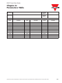
1
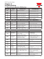
CARLO GAVAZZI
Automation
Components
VariFlex2
RVDF Series
Quick Start Guide
110V
Class 1ph
220V
Class 1ph
Class 3ph
440V
Class 3ph
0.20~0.75kW
0.25~1.0HP
0.20~2.2kW
0.25~3.0HP
1.50~2.2kW
2.0~3.0HP
0.75~2.2kW
1.0~3.0HP
RVDF Quick Start Guide
General Information
The manufacturer accepts no liability for any consequences resulting from inappropriate,
negligent or incorrect installation or adjustment of the optional parameters of the equipment
or from mismatching the variable speed drive with the motor.
The contents of this guide are believed to be correct at the time of printing. In the interests of
commitment to a policy of continuous development and improvement, the manufacturer
reserves the right to change the specification of the product or its performance, or the
content of the guide without notice.
All rights reserved. No parts of this guide may be reproduced or transmitted in any form or by
any means, electrical or mechanical including, photocopying, recording or by an information
storage or retrieval system, without permission in writing from the publisher.
Environmental Statement
The electronic variable speed drives have the potential to save energy and (through increased
machine/process efficiency) reduce raw material consumption and scrap throughout their
long working lifetime. In typical applications, these positive environmental effects far
outweigh the negative impacts of product manufacture and end-of-life disposal.
Nevertheless, when the products eventually reach the end of their useful life, they can very
easily be dismantled into their major component parts for efficient recycling. Many parts snap
together and can be separated without the use of tools, while other parts are secured with
conventional screws.
Virtually all parts of the product are suitable for recycling.
Product packaging is of good quality and can be re-used. All the products come in strong
cardboard cartons which themselves have a high recycled fibre content. If not re-used, these
containers can be recycled. Polythene, used on the protective film and bags from wrapping
product, can be recycled in the same way. Carlo Gavazzi packaging strategy favours easily
recyclable materials of low environmental impact, and regular reviews identify opportunities
for improvement.
When preparing to recycle or dispose of any product or packaging, please observe local
legislation and best practice.
© Copyright - Carlo Gavazzi – All rights reserved - Revision. R00
Specifications are subject to change without notice. Pictures are just an example. For special features and/or customization, please ask to our sales network. 110909
RVDF Quick Start Guide
CONTENTS
Chapter 1: Introduction . . . . . . . . . . . . . . . . . . . . . . . . . . . . . . . . . . . . . . . . . . . . . . . . . . . . 4
1.1 Electrical safety – general warning . . . . . . . . . . . . . . . . . . . . . . . . . . . . . . . . . . . . . . . 4
1.2 System design and safety of personnel . . . . . . . . . . . . . . . . . . . . . . . . . . . . . . . . . . . 4
1.3 Environmental Limits . . . . . . . . . . . . . . . . . . . . . . . . . . . . . . . . . . . . . . . . . . . . . . . . . . 4
1.4 Access . . . . . . . . . . . . . . . . . . . . . . . . . . . . . . . . . . . . . . . . . . . . . . . . . . . . . . . . . . . . 4
1.5 Compliance and regulations . . . . . . . . . . . . . . . . . . . . . . . . . . . . . . . . . . . . . . . . . . . . 4
1.6 Motor . . . . . . . . . . . . . . . . . . . . . . . . . . . . . . . . . . . . . . . . . . . . . . . . . . . . . . . . . . . . . . 5
1.7 Adjusting parameters . . . . . . . . . . . . . . . . . . . . . . . . . . . . . . . . . . . . . . . . . . . . . . . . . 5
1.8 Electrical installation . . . . . . . . . . . . . . . . . . . . . . . . . . . . . . . . . . . . . . . . . . . . . . . . . . 5
1.8.1 Electric shock risk . . . . . . . . . . . . . . . . . . . . . . . . . . . . . . . . . . . . . . . . . . . . . . . . 5
1.8.2 Isolation device . . . . . . . . . . . . . . . . . . . . . . . . . . . . . . . . . . . . . . . . . . . . . . . . . . 5
1.8.3 STOP function . . . . . . . . . . . . . . . . . . . . . . . . . . . . . . . . . . . . . . . . . . . . . . . . . . . 5
1.8.4 Stored charge . . . . . . . . . . . . . . . . . . . . . . . . . . . . . . . . . . . . . . . . . . . . . . . . . . . 5
1.8.5 Equipment supplied by plug and socket . . . . . . . . . . . . . . . . . . . . . . . . . . . . . . . 6
1.8.6 Ground leakage current . . . . . . . . . . . . . . . . . . . . . . . . . . . . . . . . . . . . . . . . . . . . 6
Chapter 2: Hardware instructions and installation . . . . . . . . . . . . . . . . . . . . . . . . . . . . . .7
2.1 Sample Model No. Identification . . . . . . . . . . . . . . . . . . . . . . . . . . . . . . . . . . . . . . . . 7
2.2 Type Selection . . . . . . . . . . . . . . . . . . . . . . . . . . . . . . . . . . . . . . . . . . . . . . . . . . . . . . . 7
2.3 Connection Diagram . . . . . . . . . . . . . . . . . . . . . . . . . . . . . . . . . . . . . . . . . . . . . . . . . . 7
2.4 Wiring Specification and suitable Optionals . . . . . . . . . . . . . . . . . . . . . . . . . . . . . . . . 8
2.5 Description of Inverter Terminals . . . . . . . . . . . . . . . . . . . . . . . . . . . . . . . . . . . . . . . 10
2.5.1 Description of main Circuit Terminals . . . . . . . . . . . . . . . . . . . . . . . . . . . . . . . . 10
2.5.2 Control Circuitry terminal Block (TM2) Description . . . . . . . . . . . . . . . . . . . . . . 10
2.6 Outline Dimensions . . . . . . . . . . . . . . . . . . . . . . . . . . . . . . . . . . . . . . . . . . . . . . . . . . 11
2.7 DIN-Rail Mounting Diagram . . . . . . . . . . . . . . . . . . . . . . . . . . . . . . . . . . . . . . . . . . . 12
2.8 Additional DIN-Rail Installation . . . . . . . . . . . . . . . . . . . . . . . . . . . . . . . . . . . . . . . . . 12
2.9 Outline Dimensions . . . . . . . . . . . . . . . . . . . . . . . . . . . . . . . . . . . . . . . . . . . . . . . . . . 13
2.10 RVDF Size 1 - IP65 Type . . . . . . . . . . . . . . . . . . . . . . . . . . . . . . . . . . . . . . . . . . . . 14
2.10.1 Installation . . . . . . . . . . . . . . . . . . . . . . . . . . . . . . . . . . . . . . . . . . . . . . . . . . . . 14
2.10.2 Circuit diagram . . . . . . . . . . . . . . . . . . . . . . . . . . . . . . . . . . . . . . . . . . . . . . . . 14
2.10.3 Connection . . . . . . . . . . . . . . . . . . . . . . . . . . . . . . . . . . . . . . . . . . . . . . . . . . . 14
2.10.4 EMC Mounting . . . . . . . . . . . . . . . . . . . . . . . . . . . . . . . . . . . . . . . . . . . . . . . . . 14
2.11 RVDF Size 2 - IP65 Type . . . . . . . . . . . . . . . . . . . . . . . . . . . . . . . . . . . . . . . . . . . . 15
2.11.1 Installation . . . . . . . . . . . . . . . . . . . . . . . . . . . . . . . . . . . . . . . . . . . . . . . . . . . . 15
2.11.2 Circuit diagram . . . . . . . . . . . . . . . . . . . . . . . . . . . . . . . . . . . . . . . . . . . . . . . . 15
2.11.3 Connection . . . . . . . . . . . . . . . . . . . . . . . . . . . . . . . . . . . . . . . . . . . . . . . . . . . 16
2.11.4 EMC Mounting . . . . . . . . . . . . . . . . . . . . . . . . . . . . . . . . . . . . . . . . . . . . . . . . . 16
Chapter 3 Software index . . . . . . . . . . . . . . . . . . . . . . . . . . . . . . . . . . . . . . . . . . . . . . . . . 17
3.1 Keypad operating instructions . . . . . . . . . . . . . . . . . . . . . . . . . . . . . . . . . . . . . . . . . 17
3.2 Brief Keypad Operating Flowchart . . . . . . . . . . . . . . . . . . . . . . . . . . . . . . . . . . . . . . 17
3.3 Parameter List . . . . . . . . . . . . . . . . . . . . . . . . . . . . . . . . . . . . . . . . . . . . . . . . . . . . . . 18
2
Specifications are subject to change without notice. Pictures are just an example. For special features and/or customization, please ask to our sales network. 110909
Chapter 4: Troubleshooting . . . . . . . . . . . . . . . . . . . . . . . . . . . . . . . . . . . . . . . . . . . . . . .
4.1 Manual Reset Inoperative Malfunctions . . . . . . . . . . . . . . . . . . . . . . . . . . . . . . . . . .
4.2 Manual Reset Operative Malfunctions (Auto-reset inoperative) . . . . . . . . . . . . . . . .
4.3 Manual Reset and Auto-Reset Operative Malfunctions . . . . . . . . . . . . . . . . . . . . . .
4.4 Special Condition Description . . . . . . . . . . . . . . . . . . . . . . . . . . . . . . . . . . . . . . . . .
4.5 Keypad Operation Error Instruction . . . . . . . . . . . . . . . . . . . . . . . . . . . . . . . . . . . . .
4.6 General Multifunction Examination Method . . . . . . . . . . . . . . . . . . . . . . . . . . . . . . .
Chapter 5: Peripherals . . . . . . . . . . . . . . . . . . . . . . . . . . . . . . . . . . . . . . . . . . . . . . . . . . .
5.1 EMI Filter Specification . . . . . . . . . . . . . . . . . . . . . . . . . . . . . . . . . . . . . . . . . . . . . . .
5.2 Specification Input Reactor and Braking Built-In Features . . . . . . . . . . . . . . . . . . .
5.3 Specification of Braking Resistor . . . . . . . . . . . . . . . . . . . . . . . . . . . . . . . . . . . . . . .
Chapter 6: Parameters Table . . . . . . . . . . . . . . . . . . . . . . . . . . . . . . . . . . . . . . . . . . . . . .
Specifications are subject to change without notice. Pictures are just an example. For special features and/or customization, please ask to our sales network. 110909
19
19
19
19
20
20
20
22
22
22
22
23
3
RVDF Quick Start Guide
Chapter 1:
Introduction
1.1 Electrical Safety - general warning
The voltages used in the drive can cause severe electrical shock and/or burns, and could be
lethal. Extreme care is necessary at all times when working with or adjacent to the drive.
Specific warnings are given at the relevant places in this guide.
1.2 System design and safety of personnel
The drive is intended as a component for professional incorporation into complete equipment
or system. If installed incorrectly, the drive may present a safety hazard.
The drive uses high voltages and currents, carries a high level of stored electrical energy, and
is used to control equipment which can cause injury.
System design, installation, commissioning and maintenance must be carried out by personnel
who have the necessary training and experience. They must read this safety information and
this guide carefully.
The STOP and START controls or electrical inputs of the drive must not be relied upon to
ensure safety of personnel. They do not isolate dangerous voltages from the output of the
drive or from any external option unit. The supply must be disconnected by an approved
electrical isolation device before gaining access to the electrical connections.
The drive is not intended to be used for safety-related functions.
Careful consideration must be given to the function of the drive which might result in a hazard,
either through its intended behaviour or through incorrect operation due to a fault. In any
application where a malfunction of the drive or its control system could lead to or allow
damage, loss or injury, a risk analysis must be carried out, and where necessary, further
measures taken to reduce the risk - for example, an over-speed protection device in case of
failure of the speed control, or a fail-safe mechanical brake in case of loss of motor braking.
1.3 Environmental Limits
Instructions within the supplied data and information within the VariFlex2 RVDF Series
Advanced User Manual regarding transport, storage, installation and the use of the drive must
be complied with, including the specified environmental limits. Drives must not be subjected
to excessive physical force.
1.4 Access
Access must be restricted to authorised personnel only. Safety regulations which apply at the
place of use must be complied with.
The IP (Ingress Protection) rating of the drive is installation dependant. For further information,
refer to the VariFlex2 RVDF Series Advanced User Manual.
1.5 Compliance and regulations
The installer is responsible for complying with all relevant regulations, such as national wiring
regulations, accident prevention regulations and electromagnetic compatibility (EMC)
regulations. Particular attention must be given to the cross-sectional areas of conductors, the
selection of fuses and other protection, and protective earth (ground) connections.
The VariFlex2 RVDF Series Advanced User Manual contains instructions for achieving
compliance with specific EMC standards.
Within the European Union, all machinery in which this product is used must comply with the
following directives:
98/37/EC: Safety of machinery
89/336/EEC: Electromagnetic compatibility
4
Specifications are subject to change without notice. Pictures are just an example. For special features and/or customization, please ask to our sales network. 110909
RVDF Quick Start Guide
1.6 Motor
Ensure the motor is installed in accordance with the manufacturer's recommendations.
Ensure the motor shaft is not exposed. Standard squirrel cage induction motors are designed
for single speed operation. If it is intended to use the capability of a drive to run a motor at
speeds above its designed maximum, it is strongly recommended that the manufacturer is
consulted first.
Low speeds may cause the motor to overheat because the cooling fan becomes less
effective. The motor should be fitted with a protection thermistor. If necessary, an electric
force vent fan should be used. The values of the motor parameters set in the drive affect the
protection of the motor. The default values in the drive should not be relied upon. It is
essential that the correct value is entered into parameter concerning the motor rated current.
This affects the thermal protection of the motor.
1.7 Adjusting parameters
Some parameters have a profound effect on the operation of the drive. They must not be
altered without careful consideration of the impact on the controlled system. Measures must
be taken to prevent unwanted changes due to error or tampering.
1.8 Electrical installation
1.8.1 Electric shock risk
The voltages present in the following locations can cause severe electric shock and may be lethal:
• AC supply cables and connections
• DC bus, dynamic brake cables and connections
• Output cables and connections
• Many internal parts of the drive, and external option units
Unless otherwise indicated, control terminals are single insulated and must not be touched.
1.8.2 Isolation device
The AC supply must be disconnected from the drive using an approved isolation device
before any cover is removed from the drive or before any servicing work is performed.
1.8.3 STOP function
The STOP function does not remove dangerous voltages from the drive, the motor or any
external option units.
1.8.4 Stored charge
The drive contains capacitors that remain charged to a potentially lethal voltage after the AC
supply has been disconnected. If the drive has been energised, the AC supply must be
isolated at least ten minutes before work may continue.
Normally, the capacitors are discharged by an internal resistor. Under certain, unusual fault
conditions, it is possible that the capacitors may fail to discharge, or be prevented from being
discharged by a voltage applied to the output terminals. If the drive has failed in a manner
that causes the display to go blank immediately, it is possible the capacitors
will not be discharged. In this case, consult Carlo Gavazzi or their authorised distributor.
Specifications are subject to change without notice. Pictures are just an example. For special features and/or customization, please ask to our sales network. 110909
5
RVDF Quick Start Guide
1.8.5 Equipment supplied by plug and socket
Special attention must be given if the drive is installed in equipment which is connected to
the AC supply by a plug and socket. The AC supply terminals of the drive are connected to
the internal capacitors through rectifier diodes which are not intended to give safety isolation.
If the plug terminals can be touched when the plug is disconnected from the socket, a means
of automatically isolating the plug from the drive must be used (e.g. a latching relay).
1.8.6 Ground leakage current
The drive is supplied without or with an internal EMC filter capacitor fitted. If the input voltage
to the drive is supplied through an ELCB or RCD, these may trip due to the ground leakage
current. Please refer to VariFlex2 RVDF Series Advanced User Manual for further information
and how to connect correctly the EMC capacitor.
6
Specifications are subject to change without notice. Pictures are just an example. For special features and/or customization, please ask to our sales network. 110909
RVDF Quick Start Guide
Chapter 2:
Hardware Instructions and Installation
2.1 Sample Model No. Identification
2
Ordering Key
Inverter model
RVDFA120075F
Output power
220V 0.75kW 1HP
RVDF A 1 10 075 F
VariFlex2 AC Drive
Frame Size
AC Supply Phase
Drive Voltage Rating
Drive kW Rating
Options
2.2 Type Selection
A:
B:
Frame Size
Size 1
Size 2
AC Supply Phase Drive Voltage Rating
Drive kW Rating
Options
1:
1-phase
10: 110VAC
020: 0.20kW, 0.25HP Nil: No option
3:
3-phase
20: 230VAC
040: 0.40kW, 0.50HP F: Built-in filter
40: 480VAC
075: 0.75kW, 1.0HP ES: IP65 with water and dust proof switch
150: 1.5kW, 2.0HP
220: 2.2kW, 3.0HP
2.3 Connection Diagrams
frame 1
frame 2
1 phase
100~120VAC
200~240VAC
-15%~+10%
50/60Hz
L1 (R)
T1 (U)
L2 (S)
T2 (V)
IM
T3 (W)
Braking
Resistor
P
1/3 phase
200~240VAC
3 phase
380~480VAC
-15%~+10%
50/60Hz
R
L1(R) (L)
T1 (U)
L2 (S)
T2 (V)
L3 (T) (N)
T3 (W)
(3) FWD
2
1
(3) FWD
2
1
Trip relay
(6) SP1
(6) SP1
Multi function
input
(7) RESET
(7) RESET
(5) 12V
(5) 12V
CON2
CON2
(8) +10V
(8) +10V
(9) VIN
10kΩ
For factorty
test only
(10) 0V (FM-)
(9) VIN
10kΩ
0~10V
FM
Trip relay
(4) REV
(4) REV
Multi function
input
IM
For factorty
test only
(10) 0V (FM-)
0~10V
FM
(11)FM+
SW1
1
2
3
(0~10V/0~20mA/4~20mA)
(11)FM+
SW1
Grounding
1
2
3
(0~10V/0~20mA/4~20mA)
Grounding
Wire Terminations to the Inverter must be made with either UL listed field wiring lugs or UL
listed crimp type ring terminals.
Note: Braking resistor only for RVDFBxxxxxx series (frame 2).
Specifications are subject to change without notice. Pictures are just an example. For special features and/or customization, please ask to our sales network. 110909
7
RVDF Quick Start Guide
2.4 Wiring Specification and Suitable Optionals
Molded-Case Circuit Breaker / Magnetic Contact
Model Type
RVDFA110020
RVDFA110040
RVDFA120020
RVDFA120040
RVDFA110075
RVDFB120075
RVDFB120150
RVDFB120220
RVDFB340075
RVDFB340150
RVDFB240220
Molded-case circuit breaker
15A
20A
30A
15A
Wire dimension
(#14AWG) 2.0mm2
Wire dimension
(#14AWG) 2.0mm2
Wire dimension
3.5mm2
Wire dimension
3.5mm2
Terminal screw M3
Terminal screw
M3/M4
Terminal screw M4
Terminal screw M4
Primary Circuit Terminal (TM1)
Signal Terminal (TM2)
1~11
Wire dimension 0.75mm2 (#18 AWG), Terminal screw M3
Warrantee does not apply to damage caused by the following situations:
(1) Damage to the inverter caused by the lack of appropriate molded-case circuit breaker or when
a circuit breaker with too large of capacity is installed between the power supply and the inverter.
(2) Damage to the inverter caused by the magnetic contact, phase advancing capacitor, or surgeprotector installed between the inverter and the motor.
Use copper conductors only size field wiring based on 80°C wire only.
• Please utilize three-phase squirrel-cage induction motor with appropriate capacity.
• If the inverter is used to drive more than one motor, the total capacity must be smaller
than the capacity of the inverter. Additional thermal overload relays must be installed in
front of each motor. Use the F_18 at 1.0 times of the rated value specified on the motor
nameplate at 50Hz, 1.1 times of the rated value specified on the motor nameplate at 60Hz.
• Do not install phase advancing capacitors, LC, or RC component between the inverter
and the motor.
8
Specifications are subject to change without notice. Pictures are just an example. For special features and/or customization, please ask to our sales network. 110909
RVDF Quick Start Guide
Application and precautions of Peripherals
From the Power Source:
• Apply the power source at the correct rated voltage to prevent from damaging the inverter.
• A Power Disconnect or Circuit breaker must be installed between the AC power supply
and the inverter.
Molded-case circuit breaker:
• Utilize an appropriate circuit breaker that’s suitable for the rated voltage and current
ratings of the inverter to switch ON/OFF the power supply to the inverter and as additional
protection for the inverter.
• Do not operate the circuit breaker to switch ON or OFF the inverter. The circuit breaker
should be used only to supply input power and should not be used for operational sequence.
Leakage circuit breaker:
• An earth leakage circuit breaker should be added to prevent false operation cause by
leakage current and to ensure personnel safety.
Magnetic Contact:
• The Magnetic Contact can be omitted at ordinary operation. To utilize external control,
automatic restart, or breaking controller the magnetic contact must be added at the primary side.
• Do not operate the magnetic contact to switch ON or OFF the inverter.
Power improvement AC Reactor:
• If large capacity power source is applied (over 600KVA), additional AC reactor may be
added to improve power factor.
Inverter:
• Power supply input terminals L1, L2 single phase for 0.2~0.75 kW or L, N single phase for
1.5~2.2 kW) are not differentiated on phase sequence. They can be arbitrarily connected.
Their connection may be interchanged.
• Output terminal T1, T2, and T3 should be connected to the U, V, and W terminals of the
motor respectively. If motor turns in opposite direction of the inverter command, simply
exchanging two of the three wire connections will correct this problem.
• Output terminal T1, T2, and T3 must not be connected to power source to prevent from
damaging the inverter.
• Grounding terminal properly ground the grounding terminal in compliance to 200V class
type three grounding. (The 400V class type is special grounding.)
Specifications are subject to change without notice. Pictures are just an example. For special features and/or customization, please ask to our sales network. 110909
9
RVDF Quick Start Guide
2.5 Description of Inverter Terminals
2.5.1 Descriptions of Main Circuit Terminals
Symbol
Description
L1 (R)
L2 (S)
Main power input
Single-phase:
Three-phase:
L1/L2(0.2~0.75 kW) or L/N
L1/L2/L3
L3 (T)
P
Extermal braking resistor terminal (Only for RVDFBxxxxxx)
R
T1 (U)
T2 (V)
Inverter output to Motor
T3 (W)
Tightening torque for TM1 is 1 LBS-FT or 12 LBS-IN (RVDFAxxxxxx).
Tightening torque for TM1 is 1.3 LBS-FT or 16 LBS-IN (RVDFBxxxxxx).
Wire voltage rating must be a minimum of :
• 300V (for 200V power supply series);
• 600V (for 400V power supply series);
2.5.2 Control Circuitry Terminal Block (TM2) Description
Symbol
1
TRIP
2
RELAY
3
FWD (FW)
4
REV (RE)
5
+12V (12)
6
SP1 (SP)
7 RESET (RS)
Description
Fault relay output terminal & Multi function output terminal (refer to F_21)
Connection point rated capacity 250VAC/1A (30VDC / 1A)
Operation control terminals (refer to F_03)
Common point of terminal 3 / 4 / 6 / 7
Multifunction input terminals (refer to F_19)
8
+10V
Power terminal for potentiometer (Pin 3)
9
Analog input wire Wiper
Analog frequency signal input terminal (Pin 2 of potentiometer
or positive terminal of 0~10V / 4~20mA / 0~20mA)
10
Analog common point
Analog signal common point ( Pin 1 of potentiometer or
negative terminal of 0~10V / 4~20mA / 0~20mA )
Analog output positive connection point
Analog frequency signal output terminal Output terminal
signal is 0~10VDC/Fn6
11
FM+
Tightening torque for TM2 is 0.42 LBS-FT or 5.03 LBS-IN.
• Wire voltage rating must be a minimum of 300V
• Control wiring should not run in the same conduit or raceway with power or motor wiring
• Single Input and Output Terminals (TM2) Ratings are ALL Class 2
10
Specifications are subject to change without notice. Pictures are just an example. For special features and/or customization, please ask to our sales network. 110909
RVDF Quick Start Guide
Descriptions of SW function
SW1
I
Type of external signal
1
0~20mA analog signal (When F_11 is set to 1)
4~20mA analog signal (When F_11 is set to 2)
2
V
3
I
1
0~10 VDC analog signal (When F_11 is set to 1)
2
V
3
2.6 Outline Dimensions
Enclosed Metal Frame to screw
all the inverter GND connection
Enclosed Metal Frame to screw
all the inverter GND connection
Model
Length mm
A
B
C
D
Frame 1
132
116
130
8.2
Frame 2
143
127
140
8
E
F
G
Frame 1
118
61
72
Frame 2
171
108
118
Specifications are subject to change without notice. Pictures are just an example. For special features and/or customization, please ask to our sales network. 110909
11
RVDF Quick Start Guide
2.7 Din Rail Mounting Diagram
STEP 1
STEP 1
Aim and insert the 4
retention ribs of the
DIN Rail at the 4
holes in rear panel of
inverter
Use
a
small
screwdriver inserting
it into the middle rib
of DIN Rail and press
the screwdriver in
order to remove the
DIN Rail from inverter
Inserting
hole
STEP 2
STEP 1
middle rib
STEP 2
Push the DIN Rail
forward until the
middle rib grips firmly
with back panel
STEP 1
STEP 2
Retention
rib
2.8 Additional DIN Rail Installation
A mounting clamp and a 35mm width rail must be used to install the Drive on the rail.
Install Drive
Dismounting Drive
① Pull the mounting
ptlate downward.
First place the groove
on the back of
module on the upper
edge of din rail, and
then
push
the
module down to lock
up position. Finally
press the mouting
plate upward into
module.
② Rotate the inverter
module to dismount
it.
Screwdriver
Mounting Plate
12
2
1
Pull Mounting Plate
Specifications are subject to change without notice. Pictures are just an example. For special features and/or customization, please ask to our sales network. 110909
RVDF Quick Start Guide
Outline Dimensions
102.41
2.9
RESET
0
DATA
ENT
R
F
1
116.57
0
173.38
188.96
DSP
FUN
204.82
RUN
STOP
117.23
133.57
133.00
Specifications are subject to change without notice. Pictures are just an example. For special features and/or customization, please ask to our sales network. 110909
13
RVDF Quick Start Guide
2.10 RVDF Size 1 - IP65 Type
2.10.1 Installation
RESET
RUN
STOP
198.90 mm
Potentiometer
REV-0-FWD
SWITCH
DATA
ENT
DSP
FUN
POWER
SWITCH
4xM4
123.40 mm
L1 L2
100~120V
or
200-240V
50/60 Hz
Single Phases
NOTE :
1. Power supply cable : #14 AGE (2.0m )
2. Motor cable : #16 AGE (1.25m )
3. Torque value of Screw :
(1). Power/Motor cable (plug in) Therminal:
5kg-cm(4.34 in-lb)
(2). Remote control wire: 4kg-cm(3.47in-lb)
(3). Outer Cover (M4): 6kg-cm(5.20in-lb)
T1 T2 T3
3 Phases
IM
2.10.2 Circuit Diagram
POWER
SWITCH
AC
100~120
or
200~240
50/60HZ
T1
T2
T3
L1
L2
FW
REV -0-FWD
RE
SWITCH
12V
10V
Potentiometer
VI
0V
3
PHASE
IM
NOTE:
(1). Input source: single-phase (L1,L2,
)
ensuring that it is connected to a
100~120 or 200~240 supply.
(2). Output Moter: three-phase ( ,T1,T2,T3).
Caution:
• Do not start or stop the inverter using the
main circuit power.
• Please always remain REV-0-FWD switch
at 0 position. In order to keep inverter has
no running signal before power-on again
after
power
supply
interrupted.
Otherwise, injury may result.
2.10.4 EMC Mounting
2.10.3 Connection
4 x Outer cover screw
200mm
Cutting Length
of cable shield
Power supply
cable
L1,L2,
Power supply
cable
Motor cable
,T1,T2,T3
Length: Max 2M
L1,L2,
Power
supply
cable
Motor cable
,T1,T2,T3
Motor cable
Note:
TM2 Remote control
cable should be connect
to ground screw
Cable shielding
connected to
ground clamp
Plug-in terminals
14
Specifications are subject to change without notice. Pictures are just an example. For special features and/or customization, please ask to our sales network. 110909
RVDF Quick Start Guide
2.11 RVDF Size 2 - IP65
2.11.1 Installation
RESET
RUN
STOP
DATA
ENT
DSP
FUN
274.5mm
POWER
SWITCH
Potentiometer
REV-0-FWD
SWITCH
4xM4
210.0mm
L1(L) L2(N) L3
220-240V
380-480V
Single/ThreePhases
T1 T2 T3
3 Phases
IM
NOTE:
1. Power supply cable:
220V #12AWG (3.5mm²)
400V #16AWG (1.25mm²)
2. Motor cable:
220V #14AWG (2.0mm²)
400V #16AWG (1.25mm²)
3. Torque value of Screw:
(1).Power/Motor cable (TM1, TM3)
Terminal: 8 kgf-cm (6.94in-lb)
(2).Remote control wire: 4kgf-cm (3.47in-lb)
(3).Outer Cover (M4): 8kgf-cm(6.94 in-lb)
2.11.2 Circuit Diagram
POWER
SWITCH
L1 (L)
200~240
380~480
50/60HZ
L2 (N)
L3
REV -0-FWD
SWITCH
FW
RE
12V
10V
Potentiometer
VI
0V
T1
T2
T3
3
PHASE
IM
NOTE:
(1). Input source:single-phase(L1(L),L2(N), )
ensuring that it is connected to a 200/240
supply or three-plase (L1 (L), L2 (N), L3, )
ensuring that it is connected to a
200/240, 380/480V supply.
(2). Output Motor: three-phase ( , T1, T2,
T3).
Caution:
• Do not start or stop the inverter using the
main circuit power.
• Please always remain REV-0-FWD switch
at 0 position. In order to keep inverter
has no running signal before power-on
again after power supply interrupted.
Otherwise, injury may result.
TM2
RELAY RW RE 12V SP RS 10V Vi
black
red
brown
0V FM
orange green
yellow
Specifications are subject to change without notice. Pictures are just an example. For special features and/or customization, please ask to our sales network. 110909
15
RVDF Quick Start Guide
2.11.3 Connection
2.11.4 EMC Mounting
NOTE:
For ALL FILTER MODELS, additional items will be find inside the box including : [1] pc of EMC
conformed waterproof (IP65) ferrite core; [1] pc of metal fastener; [1] pc of MF Zin 5-C screw.
“CAUTION: if application use require to meet EMC regulation, you MUST first constrain the
motor cables, close the ferrite core onto the motor cable outside the plastic enclosure as stated
in the above diagram. Please also note the length of the Motor cable CANNOT exceed 5M
under EMC regulation”
16
Specifications are subject to change without notice. Pictures are just an example. For special features and/or customization, please ask to our sales network. 110909
RVDF Quick Start Guide
Chapter 3:
Software Index
3.1 Keypad Operating Instructions
CAUTION
Do not operate keypad by screwdriver or
other sharp-ended tool to avoid damaging
keypad.
3.2 Brief Keypad Operation Flowchart
(2)
(FREQ) (1)
(FREQ)
(Read)
X X
X X
X X X
After 0.5s
(Write)
X X X
Note (1) Displayed setting of frequency when stopped. Display output frequency when running.
Note (2) The setting of the frequency can be modified either when stopped or when running.
Specifications are subject to change without notice. Pictures are just an example. For special features and/or customization, please ask to our sales network. 110909
17
RVDF Quick Start Guide
3.3 Parameter List
F_
Function
Function Description
Unit
Range
0.1s
0.1s
0.1~999s
0.1~999s
Factory
setting
0
5.0
5.0
0
1
2
Accel. Time
Decel. Time
Factory Adjustment
Accel. time
Decel. time
3
Operation mode
0: Forward/Stop, Reverse/Stop
1: Run/Stop, Forward / Reverse
1
0~1
0
4
Motor rotation direction
0: Forward
1: Reverse
1
0~1
0
*1
5
V/F Pattern
V/F Pattern setting
1
1~6
1/4
*2
Frequency upper limit
0.1Hz
1.0~120Hz
(1~200) *4
50/60Hz
*3
Frequency lower limit
0.1Hz
0.0~120Hz
(1~200) *4
0.0Hz
*3
*3
6
Frequency upper/lower limit
7
8
SPI frequency
SP1 frequency
0.1Hz
1.0~120Hz
(1~200) *4
10Hz
9
JOG frequency
JOG frequency
0.1Hz
1.0~10.0Hz
(1~200) *4
6Hz
10
Start / Stop Control
0: Keypad
1: Terminal (TM2)
1
0~1
0
11
Frequency Control
0: Keypad
1: Terminal (0~10v / 0~20mA)
2: Terminal (4~20mA)
1
0~2
0
12
Carrier frequency control
Carrier Frequency Setting
1
1~5
(1~10)*4
5
13
Torque compensation
Torque compensation gain
0.1%
0.0~10.0%
0.0%
14
Stop method
0: controlled deceleration stop
1: free run to stop
1
0~1
0
15
16
17
DC braking setting
DC braking time
DC braking injection frequency
DC braking level
0.1s
0.1Hz
0.1%
0.0~25.5s
1~10Hz
0.0~20.0%
0.5s
1.5Hz
8.0%
18
Electronic thermal
Overload protection
Protection base on motor rated
current
1%
50 ~ 100%
(0~200)*4
100%
19
20
Multifunction input terminal 1 1:
2:
(SP1) function
Multifunction input connection
3:
point
4:
Multifunction input terminal 2 5:
(RESET) function
6:
Jog
Sp1
Emergency stop
External Base Block
Reset
SP2 *4
1: Operating
2: Frequency reached
3: Fault
*1 *3
*1 *3
*1
5
3
21
Multi-function output
Multifunction output terminal
22
Reverse Lock-Out
0: REV run
1: REV run Lock-Out
1
0~1
0
23
Momentary power loss
0: Enabled
1: Disabled
1
0~1
0
24
Auto restart
Number of Auto-restart times
1
0~5
0
25
Factory setting
010: Constants initialization to 50Hz system
020: Constants initialization to 60Hz system
26
27
SP2 frequency
SP3 frequency
SP2 frequency
SP3 frequency
28
Direct start
0: Enabled
1: Disabled
29
30
Software version
Fault Log
CPU program version
Fault log for three faults
NOTE:
*1: Indicate this parameter can be adjusted during running mode.
*2: Please refer to F_25.
18
Note
3
*2
0.1Hz
0.1Hz
1.0~200Hz
1.0~200Hz
20
30
*4
*4
1
0~1
0
*5
*3: If the setting range is above 100, the setting unit becomes 1.
*4: New function for CPU version V1.9 and above.
*5: New function for CPU version V2.1 and above
Specifications are subject to change without notice. Pictures are just an example. For special features and/or customization, please ask to our sales network. 110909
RVDF Quick Start Guide
Chapter 4:
Troubleshooting
4.1 Manual Reset Inoperative Malfunctions
INDICATION
CONTENT
POSSIBLE CAUSE
COUNTERMEASURE
CPF
Program error
Outside noise interference
Place a RC surge absorber in parallel with the
noise generating magnetic contact
EPR
EEPROM error
EEPROM defective
Replace EEPROM
OV
Voltage too high
1. Power source voltage too high
while not operating 2. Detection circuitry defective
1. Examine the power supply
2. Return the inverter for repair
LV
Voltage too low
1. Power source voltage too low
while not operating 2. Detection circuitry defective
1. Examining the power supply
2. Return the inverter for repair
OH
Inverter over heat
1. Detection circuit defective.
1. Return the inverter for repair
while not operating 2. Environment over-heat or poor ventilation 2. Improve ventilation
4.2 Manual Reset Operative Malfunctions (Auto-Reset inoperative)
INDICATION
CONTENT
POSSIBLE CAUSE
COUNTERMEASURE
OC
Over-current at stop
Detection circuit malfunction
condition
OL1
Motor over-load
1. Loading too large
2. Improper V/F model setting
3. Improper F_18 setting
1. Increase capacity of motor
2. Adjust to use a proper V/F curve setting
3. Adjust F_18 according to instruction
OL2
Inverter over-load
1. Loading too large
2. Improper V/F model setting
1. Increase capacity of inverter
2. Adjust to use a proper V/F curve setting
Return the inverter for repair
4.3 Manual Reset and Auto-Reset Operative Malfunctions
INDICATION
CONTENT
POSSIBLE CAUSE
COUNTERMEASURE
OCS
Transient overcurrent starting
machine
1. Motor coil short-circuit with external casing
1. Examining motor
2. Motor connection wire short-circuit
2. Examining wiring
with grounding
3. Replace transistor module
3. Transistor module damaged
OCA
Over-current at
acceleration
1. Acceleration time setting too short
2. Improper V/F feature selection
3. Applied motor capacity
exceeds inverter capacity
OCC
Over-current at
steady speed
1. Examining the loading configuration
1. Transient alteration of the loading
2. Install inductor on the power supply
2. Transient alteration of the power supply
input side
OCd
Over-current at
deceleration
Deceleration setting too short
OCb
Over-current at
breaking
DC Breaking frequency, breaking Adjust to reduce settings of F_15, F_16, or
voltage, or breaking time setting too long F_17
OVC
Over-voltage at
operation /
deceleration
1. Adjust to use a longer deceleration time
1. Deceleration time setting too short or
2. Install a inductor on the power supply
inertial loading too large
input side
2. Power supply voltage variation too large
3. Increase the capacity of inverter
LVC
OHC
1. Adjust acceleration time to longer setting
2. Adjust to a proper V/F curve
3. Replace and install another inverter
with appropriate capacity
Adjust to use a longer acceleration time
1.
1. Power supply voltage too low
2.
2. Power supply voltage variation too 3.
large
4.
Improve power source quality
Adjust to use a longer acceleration time
Insufficient voltage
Increase capacity of inverter
level at operation
Install a reactor on the power supply
input side
1. Loading too heavy
1. Examining the loading
Heat-sink over
2. Ambient temperature too high or poor 2. Increase capacity of inverter
heated at operation
ventilation
3. Improve ventilation
Specifications are subject to change without notice. Pictures are just an example. For special features and/or customization, please ask to our sales network. 110909
19
RVDF Quick Start Guide
4.4 Special Condition Description
INDICATION
SP0
SP1
SP2
E.S.
b.b.
CONTENT
Zero Speed
Stopping
POSSIBLE CAUSE
When F_11 = 0, F_7= 0 and frequency setting < 1 Hz
When F_11 = 1, F_7<(F_6/100), and frequency setting <(F_6/100)
1. If the inverter is set to external operation (F_10 = 1) and direct start is disabled
(F_28 =1), the inverter cannot be started and will flash SP1 when operation
Fail to start directly
switch turned to ON after applying power (see descriptions of F_28).
2. Direct start is possible when F_28 = 0.
The inverter setup to external operation (F_10=1). If the STOP key in the keypad is
Keypad emergency pressed at the middle of operation, the inverter stops according the setting in F_14
stop
and flash SP2 after stop. The RUN switch must be turned OFF than ON to restart the
machine.
When the external emergency stop signal is activated through the multi-function
External emergency
input terminal, the inverter decelerates and stops. Inverter flashes E.S. after stops.
stop
(Refer to instruction for F_19 for detail).
When the external BASE BLOCK signal is activated through the multifunction
External BASE
terminal, the inverter stop output immediately and flash b.b. for indication. (Refer to
BLOCK
instruction for F_19 for detail)
4.5 Keypad Operation Error Instruction
INDICATION
CONTENT
POSSIBLE CAUSE
COUNTERMEASURE
Motor direction
locked
1. Attempt to reverse direction when
1. Adjust F_22 to 0
F_22 = 1
2. Adjust F_04 to 0
2. Attempt to set F_22 to 1 when F_04=1
Er1
Keypad operation
error
1. Press ▲ or ▼ keys when F_11=1 or
under sp1 operation
1. Use ▲ or ▼ keys to adjust frequency
2. Attempt to modify F_29
setting only after F_11=0
3.Attempt to modify parameter that is 2. Do not modify F_29
not allowed to be modified during 3. Modify in stop mode
operation (refer to parameter list)
Er2
Parameter setting
error
1. F_6≦F_7
LOC
1. F_6 > F_7
4.6 General Malfunction Examination Method
ABNORMALITY
Motor
Inoperative
CHECK POINT
Is the power source voltage delivered to L1, L2
terminal (is the charging indicator illuminated)?
• Check if the power source on.
• Turn power source OFF and then ON again.
• Reconfirm the power voltage level.
Is there voltage output from output terminal T1, T2
and T3?
• Turn power source OFF and then ON again
Is the motor wired correctly?
• Check motor wiring.
Is there any abnormal condition of the inverter?
• Refer to malfunction handling instructions to
examine and correct wiring.
Is the forward or reverse instruction loaded?
Motor
Inoperative
Motor
operate in
opposite
direction
20
COUNTERMEASURE
Is the analog frequency setting loaded?
• Check to see if wiring for analog frequency input
signal is correct?
If the operation mode setting correct?
• Check if the frequency input setting voltage is correct?
Is wiring on the output terminals T1, T2 and T3 correct? • Operate by digital?
Is the wiring for the forward and reverse signals
correct?
• Wiring should be in accordance with the U, V, W
terminals of motor.
Specifications are subject to change without notice. Pictures are just an example. For special features and/or customization, please ask to our sales network. 110909
RVDF Quick Start Guide
4.6 General Malfunction Examination Method
ABNORMALITY
Motor
operation
speed fixed
Motor
operation
at speed
too high or
too low
Abnormal
speed
variation at
operation
CHECK POINT
COUNTERMEASURE
Is the wiring for analog frequency input correct?
• Examining the wiring and correct it.
Is the operation mode setting correct?
• Examining the wiring and correct it.
Is the loading too heavy?
• Check the Operation panel
Is the specification of motor (poles, voltage) correct? • Reduce loading
Is the gear ratio correct?
• Reconfirm motor specification.
Is the highest output frequency setting correct?
• Reconfirm gear ratio
Is the voltage on motor side reduced extremely?
• Reconfirm highest output frequency
Is the loading too heavy?
• Reduce loading variation
Is the loading variation too large?
• Increase inverter and motor capacity
Is the input power source steady and stable?
• Install AC reactor on the power supply input side
Specifications are subject to change without notice. Pictures are just an example. For special features and/or customization, please ask to our sales network. 110909
21
RVDF Quick Start Guide
Chapter 5:
Peripherals
5.1 EMI Filter Specification
Model
Dimension (mm)
Current (A)
CFFB42-A10-R
133 x 51 x 44
10A
RVDFA110020 - RVDFA120020F
RVDFA110040 - RVDFA120040F
RVDFA110075 - RVDFA120075F
CFFB42-A20-R
99 x 84 x 68
20A
RVDFB120150F - RVDFB120220F
120 x 58 x 58
10A
RVDFB340075F - RVDFB340150F
RVDFB340220F
only for 1-phase configuration
CFFB43-A10-R106
Inverter model
5.2 Specification Input Reactor and Braking Built-In Features
Model
RVDFA120020F
RVDFA120040F
RVDFA120075F
RVDFB120150F
RVDFB120220F
RVDFB340075F
RVDFB340150F
RVDFB340220F
✔: Built-in
Input AC Reactor
Braking transistor
build-in
Braking resister
build-in
Torque of braking
✘
✘
✘
Current (A)
Inductance (mH)
20%
3.0
7.0
✘
20%
5.2
4.2
✘
✘
20%
9.4
2.1
✔
✘
20%
19
1.1
✔
✘
20%
25
0.71
✔
✘
20%
2.5
8.4
✔
✘
20%
5.0
4.2
✔
✘
20%
7.5
3.6
✘: Without Built-in
NOTE
1: Without transistor and resistor built-in.
5.3 Specification of Braking Resistor
Model of Inverter
RVDFB120150F
RVDFB120220F
RVDFB340075F
RVDFB340150F
RVDFB340220F
Specification of Braking Resistor
Rate of Motor
(kW)
Braking Resistor Torque of braking
ED(%)
(%)
(W)
(Ω)
1.5
150
100
10
119
2.2
200
70
9
116
0.75
60
750
8
125
1.5
150
400
10
119
2.2
200
250
8
128
NOTE:
1. Braking level: 200 V: 385 Vdc
400 V: 770 Vdc
2. Braking resistor not admitted for RVDFAxxxxxx
3. Braking resistor mounting is below:
5cm
Inverter
P R
TM1
Braking Resistor
22
Specifications are subject to change without notice. Pictures are just an example. For special features and/or customization, please ask to our sales network. 110909
RVDF Quick Start Guide
Chapter 6:
Parameters Table
Customer
Inverter
Model
Using Site
Contact
Phone
Address
Parameter
Code
Setting
Content
Parameter
Code
Setting
Content
Parameter
Code
F-00
F-11
F-22
F-01
F-12
F-23
F-02
F-13
F-24
F-03
F-14
F-25
F-04
F-15
F-26
F-05
F-16
F-27
F-06
F-17
F-28
F-07
F-18
F-29
F-08
F-19
F-30
F-09
F-20
F-10
F-21
Specifications are subject to change without notice. Pictures are just an example. For special features and/or customization, please ask to our sales network. 110909
Setting
Content
23
OUR SALES NETWORK IN EUROPE
AUSTRIA - Carlo Gavazzi GmbH
Ketzergasse 374, A-1230 Wien
Tel: +43 1 888 4112
Fax: +43 1 889 10 53
[email protected]
FRANCE - Carlo Gavazzi Sarl
Zac de Paris Nord II, 69, rue de la Belle
Etoile, F-95956 Roissy CDG Cedex
Tel: +33 1 49 38 98 60
Fax: +33 1 48 63 27 43
[email protected]
BELGIUM - Carlo Gavazzi NV/SA
Schaarbeeklei 213/3, B-1800 Vilvoorde
Tel: +32 2 257 4120
Fax: +32 2 257 41 25
[email protected]
DENMARK - Carlo Gavazzi Handel A/S
Over Hadstenvej 38, DK-8370 Hadsten
Tel: +45 89 60 6100
Fax: +45 86 98 15 30
[email protected]
FINLAND - Carlo Gavazzi OY AB
Petaksentie 2-4, FI-00630 Helsinki
Tel: +358 9 756 2000
Fax: +358 9 756 20010
[email protected]
GERMANY - Carlo Gavazzi GmbH
Rudolf-Diesel-Strasse 23,
D-64331 Weiterstadt
Tel: +49 6151 81000
Fax: +49 6151 81 00 40
[email protected]
GREAT BRITAIN - Carlo Gavazzi UK Ltd
7 Springlakes Industrial Estate,
Deadbrook Lane, Hants GU12 4UH,
GB-Aldershot
Tel: +44 1 252 339600
Fax: +44 1 252 326 799
[email protected]
ITALY - Carlo Gavazzi SpA Via Milano 13, I-20020 Lainate
Tel: +39 02 931 761
Fax: +39 02 931 763 01
[email protected]
NETHERLANDS - Carlo Gavazzi BV
Wijkermeerweg 23,
NL-1948 NT Beverwijk
Tel: +31 251 22 9345
Fax: +31 251 22 60 55
[email protected]
NORWAY - Carlo Gavazzi AS
Melkeveien 13, N-3919 Porsgrunn
Tel: +47 35 93 0800
Fax: +47 35 93 08 01
[email protected]
PORTUGAL - Carlo Gavazzi Lda
Rua dos Jerónimos 38-B,
P-1400-212 Lisboa
Tel: +351 21 361 7060
Fax: +351 21 362 13 73
[email protected]
SPAIN - Carlo Gavazzi SA
Avda. Iparraguirre, 80-82,
E-48940 Leioa (Bizkaia)
Tel: +34 94 480 4037
Fax: +34 94 480 10 61
[email protected]
SWEDEN - Carlo Gavazzi AB
Nattvindsgatan 1, S-65221 Karlstad
Tel: +46 54 85 1125
Fax: +46 54 85 11 77
[email protected]
SWITZERLAND - Carlo Gavazzi AG
Verkauf Schweiz/Vente Suisse
Sumpfstrasse 32,
CH-632 Steinhausen
Tel: +41 41 747 4535
Fax: +41 41 740 45 40
[email protected]
OUR SALES NETWORK IN NORTH AMERICA
USA - Carlo Gavazzi Inc.
750 Hastings Lane,
USA-Buffalo Grove, IL 60089,
Tel: +1 847 465 6100
Fax: +1 847 465 7373
[email protected]
CANADA - Carlo Gavazzi Inc.
2660 Meadowvale Boulevard,
CDN-Mississauga Ontario L5N 6M6,
Tel: +1 905 542 0979
Fax: +1 905 542 22 48
[email protected]
CANADA - Carlo Gavazzi LTEE
3777 Boulevard du Tricentenaire
Montreal, Quebec H1B 5W3
Tel: +1 514 644 2544
Fax: +1 514 644 2808
[email protected]
OUR SALES NETWORK IN ASIA AND PACIFIC
MALAYSIA - Carlo Gavazzi
Automation (M) Sdn Bhd.
54, Jalan Rugbi 13/30,
Tadisma Business Park Seksyen13
40100 Shah Alam, Selangor
Tel: +60 3 55 121162
Fax: + 60 3 55 126098
CHINA - Carlo Gavazzi Automation
(China) Co. Ltd.
Rm. 2308 - 2310, 23/F.,
News Building, Block 1,
1002 Shennan Zhong Road,
Shenzhen, China
Tel: +86 755 83699500
Fax: +86 755 83699300
HONG KONG - Carlo Gavazzi
Automation Hong Kong Ltd.
Unit 3 12/F Crown Industrial Bldg.,
106 How Ming St., Kowloon,
Hong Kong
Tel: +852 23041228
Fax: +852 23443689
Carlo Gavazzi Industri A/S
Hadsten - DENMARK
Carlo Gavazzi Ltd
Zejtun - MALTA
Carlo Gavazzi Controls SpA
Controls Division
Belluno - ITALY
Carlo Gavazzi Controls SpA
Sensors Division
Castel Maggiore (BO) - ITALY
Uab Carlo Gavazzi Industri Kaunas
Kaunas - LITHUANIA
Carlo Gavazzi Automation
(Kunshan) Co., Ltd.
Kunshan - CHINA
SINGAPORE - Carlo Gavazzi Automation
Singapore Pte. Ltd.
No. 178 Paya Lebar Road
#04-01/05 409030 Singapore
Tel: +65 67 466 990
Fax: +65 67 461 980
MAN QUICK RVDF ENG - REV.0 09/09
OUR PRODUCTION SITES
HEADQUARTERS
Carlo Gavazzi Automation SpA
Via Milano, 13 - I-20020
Lainate (MI) - ITALY
Tel: +39 02 931761
[email protected]
www.carlogavazzi.com/ac
CARLO GAVAZZI
Automation
Components
Further information on
www.gavazziautomation.com - www.carlogavazzi.com/ac