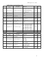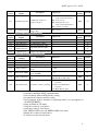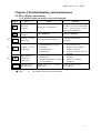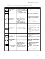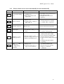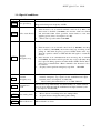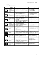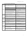
1
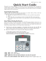
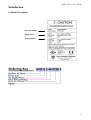
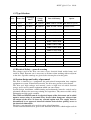
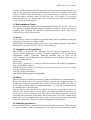
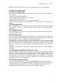
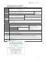
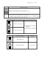
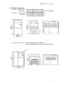
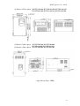
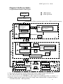
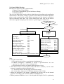
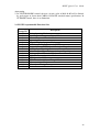
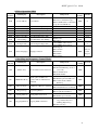
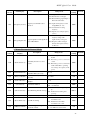
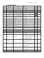
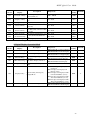
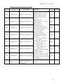
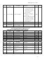
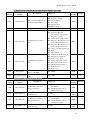
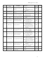
CARLO GAVAZZI
Automation
Components
VariFlex2
RVCF series
Quick Start Guide
230V
Class 1ph or 3ph
480V
Class 3ph
0.4~30.0kW
0.5~40HP
0.75~55kW
1.0~75HP
RVCF Quick User Guide
General Information
The manufacturer accepts no liability for any consequences resulting from inappropriate, negligent or
incorrect installation or adjustment of the optional parameters of the equipment or from mismatching
the variable speed drive with the motor.
The contents of this guide are believed to be correct at the time of printing. In the interests of
commitment to a policy of continuous development and improvement, the manufacturer reserves the
right to change the specification of the product or its performance, or the content of the guide without
notice.
All rights reserved. No parts of this guide may be reproduced or transmitted in any form or by any
means, electrical or mechanical including, photocopying, recording or by an information storage or
retrieval system, without permission in writing from the publisher.
Drive Software Version
This product is supplied with the latest version of user-interface and machine control software. If this
product is to be used in a new or existing system with other drives, there may be some differences
between their software and the software in this product. These differences may cause the product to
function differently. This may also apply to drives returned from the Carlo Gavazzi Service Centre.
If there is any doubt, please contact your local Carlo Gavazzi representative or Distributor.
Environmental Statement
The electronic variable speed drives have the potential to save energy and (through increased
machine/process efficiency) reduce raw material consumption and scrap throughout their long
working lifetime. In typical applications, these positive environmental effects far outweigh the
negative impacts of product manufacture and end-of-life disposal.
Nevertheless, when the products eventually reach the end of their useful life, they can very easily be
dismantled into their major component parts for efficient recycling. Many parts snap together and can
be separated without the use of tools, while other parts are secured with conventional screws.
Virtually all parts of the product are suitable for recycling.
Product packaging is of good quality and can be re-used. All the products come in strong cardboard
cartons which themselves have a high recycled fibre content. If not re-used, these containers can be
recycled. Polythene, used on the protective film and bags from wrapping product, can be recycled in
the same way. Carlo Gavazzi' packaging strategy favours easily recyclable materials of low
environmental impact, and regular reviews identify opportunities for improvement.
When preparing to recycle or dispose of any product or packaging, please observe local legislation
and best practice.
© Copyright - Carlo Gavazzi – All rights reserved
Revision. R00
1
RVCF Quick User Guide
Quick Start Guide
This guide is to assist in installing and running the inverter to verify that the drive and motor are
working properly. Starting, stopping and speed control will be from the keypad. If your application
requires external control or special system programming, consult the RVCF Advanced User Manual
supplied with the CD in your inverter .
Step 0 Products Inspection
Carlo Gavazzi’s inverters are all passed the function test before delivery. Please check the
followings when you received and unpacked the inverter:
The model and capacity of the inverter are the same as those specified in your purchase
order.
Check where there are any damages caused by transportation. Please do not apply the
power, and do contact Carlo Gavazzi’s sales representatives if any of the above problems
happened.
Step 1 Before Starting the Inverter
Please review Preface and Safety Precautions of the RVCF Instruction Manual. Verify drive was
installed in accordance with the procedures as described in RVCF Ambient Environment and
Installation. If you feel this was abnormal, do not start the drive until qualified personnel have
corrected the situation. (Failure to do so could result in serious injury.)
Check inverter and motor nameplates to determine that they have the same HP and
voltage ratings. (Ensure that full load motor amps do not exceed that of the inverter.)
Remove the terminal cover to expose the motor and power terminals.
a. Verify that AC power is wired to L1, L2, and L3.
b. Verify that Motor leads are connected to T1, T2, and T3.
(The two leads may need to be reversed if motor rotation is not correct).
1. SEQ LED : 1_00 =1, LED Lit.
2. FRQ LED : 1_06 = 1/2/3/4, LED Lit
3. FWD LED: Forward Direction, LED action(Flash in stop, Keep Lit in operation).
4. REV LED : Reverse Direction, LED action(Flash in stop, Keep Lit in operation).
5. Four action of FUN, Hz/RPM, VOLT, AMP LED and display of four 7-segment display, refer
2
RVCF Quick User Guide
to operation description of the keypad.
6. LCD keypad without FUN, Hz/RPM, VOLT, AMP LED.
Step 2 Apply Power to the Drive
Apply AC power to the Drive and observe Operator. Four 7-segment Display should read
Power Voltage for 3~5 seconds and then read Frequency/Speed, 05.00. Four 7-segment
Display and FWD LED should be flashed all the time.
Step 3 Check Motor Rotation Without Load
Press RUN key (FWD LED should light); Four 7-segment Display should run from 00.00 to
05.00.
Check motor rotation. If it is not correct:
Press STOP key. Remove AC power. Wait for LED “charge” lamp to extinguish.
Reverse motor leads T1 and T2. Restart the drive and check new rotation.
Press STOP key to stop the drive.
Step 4 Check Full Speed at 50Hz/60Hz
Frequency/Speed can be changed by pressing the up or down Arrow keys. To move right or
left for next digit, press SHIFT / RESET key. Press the READ / ENTER key to set the speed.
Set frequency up to 50Hz/60Hz in accordance with the last rule.
Press RUN key. Check drive acceleration to full speed.
Press STOP key to stop drive and check deceleration.
3
RVCF Quick User Guide
CONTENTS
Quick Start Guide........................................................................................................ 2
Contents ...................................................................................................................... 4
Introduction................................................................................................................. 5
i.1 Model description ........................................................................................................... 5
i.2 Type Selection ................................................................................................................ 6
i.3 Electrical Safety - general warning.................................................................................. 6
i.4 System design and safety of personnel .......................................................................... 6
i.5 Environmental Limits ...................................................................................................... 7
i.6 Access............................................................................................................................ 7
i.7 Compliance and regulations ........................................................................................... 7
i.8 Motor .............................................................................................................................. 7
i.9 Adjusting parameters ...................................................................................................... 7
i.10 Electrical installation ..................................................................................................... 8
i.10.1 Electric shock risk................................................................................................ 8
i.10.2 Isolation device ................................................................................................... 8
i.10.3 STOP function ..................................................................................................... 8
i.10.4 Stored charge...................................................................................................... 8
i.10.5 Equipment supplied by plug and socket .............................................................. 8
i.10.6 Ground leakage current....................................................................................... 8
Chapter 1 Notice for wiring ........................................................................................ 9
1.1 Fuse types ..................................................................................................................... 9
1.2 Precautions for peripheral applications..........................................................................11
1.3 RVCF Wiring diagram ................................................................................................. 12
1.4 Descriptions of Inverter terminal................................................................................... 14
1.5 Dimensions .................................................................................................................. 16
Chapter 2 Software index......................................................................................... 18
2.1 Operation Instruction of the keypad.............................................................................. 18
2.2 Control Mode Selection ................................................................................................ 19
2.3 Programmable function list ........................................................................................... 20
Chapter 3 Troubleshooting and maintenance ....................................................... 32
3.1 Error display and remedy ............................................................................................. 32
3.1.1 Error which can not be recovered manually ......................................................... 32
3.1.2 Error which can be recovered manually and automatically................................... 33
3.1.3 Error which can be recovered manually but not automatically .............................. 34
3.1.4 Special conditions ................................................................................................ 35
3.1.5 Operation errors................................................................................................... 36
3.2 General functional troubleshooting .................................................................. 37
Appendix 1 : RVCF parameter setting list............................................................... 38
Appendix 2 : CE Certificate...................................................................................... 39
Appendix 3 : APPROVALS Table UL listing and CE Certification ......................... 40
4
RVCF Quick User Guide
Introduction
i.1 Model description
Inverter model
Input power
Output power
5
RVCF Quick User Guide
i.2 Type Selection
Series
Frame Size
AC Supply
Phase
Drive
Voltage
Rating
Drive kW Rating
Option
RVCF A: Size1
1: 1-Phase
20: 230VAC
0040: 0.40kW, 0.50 HP Nil: Without Options
B: Size2
3: 3-Phase
40: 480VAC
0075: 0.75kW, 1.0 HP
C: Size3
0150: 1.5kW, 2.0 HP
D: Size4
0220: 2.2kW, 3.0 HP
E: Size5
0370: 3.70kW, 5HP
F: Size6
0550: 5.50kW, 7.5HP
F: Built-in filter
0750: 7.50kW, 10HP
1100: 11.0kW, 15HP
1500: 15.0kW, 20HP
1850: 18.5kW, 25HP
2200: 22.0kW, 30HP
3000: 30.0kW, 40HP
3700: 37.0kW, 50HP
4500: 45.0kW, 60HP
5500: 55.0kW, 75HP
i.3 Electrical Safety - general warning
The voltages used in the drive can cause severe electrical shock and/or burns, and
could be lethal. Extreme care is necessary at all times when working with or adjacent
to the drive. Specific warnings are given at the relevant places in this guide.
i.4 System design and safety of personnel
The drive is intended as a component for professional incorporation into complete
equipment or system. If installed incorrectly, the drive may present a safety hazard.
The drive uses high voltages and currents, carries a high level of stored electrical
energy, and is used to control equipment which can cause injury.
System design, installation, commissioning and maintenance must be carried out by
personnel who have the necessary training and experience. They must read this safety
information and this guide carefully.
The STOP and START controls or electrical inputs of the drive must not be relied
upon to ensure safety of personnel. They do not isolate dangerous voltages from
the output of the drive or from any external option unit. The supply must be
disconnected by an approved electrical isolation device before gaining access to
the electrical connections.
The drive is not intended to be used for safety-related functions.
Careful consideration must be given to the function of the drive which might result in
6
RVCF Quick User Guide
a hazard, either through its intended behaviour or through incorrect operation due to a
fault. In any application where a malfunction of the drive or its control system could
lead to or allow damage, loss or injury, a risk analysis must be carried out, and where
necessary, further measures taken to reduce the risk - for example, an over-speed
protection device in case of failure of the speed control, or a fail-safe mechanical brake
in case of loss of motor braking.
i.5 Environmental Limits
Instructions within the supplied data and information within the VariFlex2 Advanced
User Manual regarding transport, storage, installation and the use of the drive must be
complied with, including the specified environmental limits. Drives must not be
subjected to excessive physical force.
i.6 Access
Access must be restricted to authorised personnel only. Safety regulations which apply
at the place of use must be complied with.
The IP (Ingress Protection) rating of the drive is installation dependant. For further
information, refer to the VariFlex2 Advanced User Manual.
i.7 Compliance and regulations
The installer is responsible for complying with all relevant regulations, such as
national wiring regulations, accident prevention regulations and electromagnetic
compatibility (EMC) regulations. Particular attention must be given to the
cross-sectional areas of conductors, the selection of fuses and other protection, and
protective earth (ground)
connections.
The VariFlex2 Advanced User Manual contains instructions for achieving compliance
with specific EMC standards.
Within the European Union, all machinery in which this product is used must comply
with the following directives:
98/37/EC: Safety of machinery
89/336/EEC: Electromagnetic compatibility
i.8 Motor
Ensure the motor is installed in accordance with the manufacturer's recommendations.
Ensure the motor shaft is not exposed. Standard squirrel cage induction motors are
designed for single speed operation. If it is intended to use the capability of a drive to
run a motor at speeds above its designed maximum, it is strongly recommended that
the manufacturer is consulted first.
Low speeds may cause the motor to overheat because the cooling fan becomes less
effective. The motor should be fitted with a protection thermistor. If necessary, an
electric force vent fan should be used. The values of the motor parameters set in the
drive affect the protection of the motor. The default values in the drive should not be
relied upon. It is essential that the correct value is entered into parameter concerning
the motor rated current. This affects the thermal protection of the motor.
i.9 Adjusting parameters
Some parameters have a profound effect on the operation of the drive. They must not
be altered without careful consideration of the impact on the controlled system.
7
RVCF Quick User Guide
Measures must be taken to prevent unwanted changes due to error or tampering.
i.10 Electrical installation
i.10.1 Electric shock risk
The voltages present in the following locations can cause severe electric shock and
may be lethal:
• AC supply cables and connections
• DC bus, dynamic brake cables and connections
• Output cables and connections
• Many internal parts of the drive, and external option units
Unless otherwise indicated, control terminals are single insulated and must not be
touched.
i.10.2 Isolation device
The AC supply must be disconnected from the drive using an approved isolation
device before any cover is removed from the drive or before any servicing work is
performed.
i.10.3 STOP function
The STOP function does not remove dangerous voltages from the drive, the motor or
any external option units.
i.10.4 Stored charge
The drive contains capacitors that remain charged to a potentially lethal voltage after
the AC supply has been disconnected. If the drive has been energised, the AC supply
must be isolated at least ten minutes before work may continue.
Normally, the capacitors are discharged by an internal resistor. Under certain, unusual
fault conditions, it is possible that the capacitors may fail to discharge, or be prevented
from being discharged by a voltage applied to the output terminals. If the drive has
failed in a manner that causes the display to go blank immediately, it is possible the
capacitors
will not be discharged. In this case, consult Carlo Gavazzi or their authorised
distributor.
i.10.5 Equipment supplied by plug and socket
Special attention must be given if the drive is installed in equipment which is
connected to the AC supply by a plug and socket. The AC supply terminals of the
drive are connected to the internal capacitors through rectifier diodes which are not
intended to give safety isolation. If the plug terminals can be touched when the plug is
disconnected from the socket, a means of automatically isolating the plug from the
drive must be used (e.g. a latching relay).
i.10.6 Ground leakage current
The drive is supplied without or with an internal EMC filter capacitor fitted. If the
input voltage to the drive is supplied through an ELCB or RCD, these may trip due to
the ground leakage current. Please refer to VariFlex2 Advanced User Manual for
further information and how to connect correctly the EMC capacitor.
8
RVCF Quick User Guide
Chapter 1 Notice for Wiring
1.1 Fuse types
Drive input fuses are provided to disconnect the drive from power in the event that a component
fails in the drive’s power circuitry. The drive’s electronic protection circuitry is designed to clear
drive output short circuits and ground faults without blowing the drive input fuses. Below table
shows the RVCF input fuse ratings.
To protect the inverter most effectively, use fuses with current-limit function.
RK5, CC/T TYPE FUSE FOR RVCF
230V class(1φ)
MODEL
HP
KW
KVA
RVCF A1200040
0.5
0.4
1.2
100% CONT
Output AMPS (A)
3.1
Max.RK5
Max.CC or T
FUSE Rating(A) FUSE Rating(A)
10
20
RVCF A1200075
1
0.75
1.7
4.5
15
30
RVCF B1200150
2
1.5
2.9
7.5
20
40
RVCF B1200220
3
2.2
4.0
10.5
25
50
MODEL
HP
KW
KVA
RVCF A3200040
0.5
0.4
1.2
100% CONT
Output AMPS (A)
3.1
RVCF A3200075
1
0.75
1.7
4.5
12
15
RVCF A3200150
2
1.5
2.9
7.5
15
20
RVCF B3200220
3
2.2
4.0
10.5
20
30
RVCF B3200370
5
3.7
6.7
17.5
30
50
RVCF C3200550
7.5
5.5
9.9
26
50
60
RVCF C3200750
10
7.5
13.3
35
60
70
RVCF D3201100
15
11.0
20.6
48
80
100
RVCF D3201500
20
15.0
27.4
64
100
125
RVCF D3201850
25
18.5
34.0
80
125
150
RVCF E3202200
30
22.0
41.0
96
160
200
RVCF E3203000
40
30.0
54.0
130
200
250
MODEL
HP
KW
KVA
RVCFA3400075
1
0.75
1.7
100% CONT
Output AMPS (A)
2.3
RVCFA3400150
2
1.5
2.9
3.8
10
15
RVCF B3400220
3
2.2
4.0
5.2
10
20
RVCF B3400370
5
3.7
6.7
8.8
20
30
RVCF C3400550
7.5
5.5
9.9
13
25
35
RVCF C3400750
10
7.5
13.3
17.5
30
50
RVCF C3401100
15
11.0
20.6
25
50
60
RVCF D3401500
20
15.0
27.4
32
60
70
RVCF D3401850
25
18.5
34.0
40
70
80
RVCF D3402200
30
22.0
41.0
48
80
100
RVCF E3403000
40
30.0
54.0
64
100
125
RVCF E3403700
50
37.0
68.0
80
125
150
RVCF F3404500
60
45.0
82.0
96
150
200
RVCF F3405500
75
55.0
110.0
128
200
250
230V class(3φ)
Max.CC or T
Max.RK5
FUSE Rating(A) FUSE Rating(A)
8
10
480V class(3φ)
Max.RK5
Max.CC or T
FUSE Rating(A) FUSE Rating(A)
6
10
*Fuse ratings are based upon 300V fuses for 230V inverter, and 500V for 480V inverters
9
RVCF Quick User Guide
Notice
To avoid shock hazards, do not touch any electrical component when the power is
applied or just after five minutes the power plug is unplugged. The other action
should be performed after the charge indicator went off.
Do not perform wiring on the inverter while it is still electrified. Disregard of this
notice could cause serious injure or death to persons.
This product is designed to use in Pollution Degree 2 environment or equivalent
environments.
10
RVCF Quick User Guide
1.2 Precautions for peripheral applications:
Molded-case
circuit breaker
Magnetic
contactor
AC reactor
for power
improvement
Install fast
action fuse
Input noise
filter
RVCF inverter
Ground
Three-phase
cage motor
Ground
Power supply:
Make sure the voltage applied is correct to avoid
damaging the inverter.
A molded-case circuit breaker must be installed
between the AC source and the inverter.
Molded-case circuit breaker:
Use a molded-case circuit breaker that conforms to
the rated voltage and current of the inverter to
control the power ON/OFF and protect the inverter.
Do not use the inverter as the switch for run/stop
switch.
Leakage breaker:
Install a leakage breaker to prevent error operation
caused by electric leakage and to protect operators.
Setting current should be 200mA or above and the
operating time at 0.1 second or longer to prevent
malfunction.
Magnetic contactor:
Normal operations do not need a magnetic
contactor. But a contactor has to be installed in
primiary side when performing functions such as
external control and auto restart after power failure,
or when using brake controller.
Do not use the magnetic contactor as the run/stop
switch of the inverter.
AC reactor for power improvement:
When inverters below 230V/480V 15KW are
supplied with high capacity (above 600KVA) power
source or an AC reactor can be connected to improve
the power performance.
Install fast action fuse:
To ensure the safety of peripheral devices, please
install the fast action fuse. Regarding the
specification, please refer to P3-4.
Input noise filter:
A filter must be installed when there are inductive
load around the inverter.
Inverter:
Input power terminals L1, L2, and L3 can be used in
any sequence regardless of phases.
Output terminals T1, T2, and T3 are connected to U,
V, and W terminals of the motor. If the motor is
reversed while the inverter is forward, just swap any
two terminals of T1, T2, and T3.
To avoid damaging the inverter, do not connect the
input terminals T1, T2, and T3 to AC power.
Connect the ground terminal properly. 200 V series:
class 3 grounding, <100Ω; 480 V series : <10Ω.
11
RVCF Quick User Guide
1.3 Wiring diagram RVCF series inverter
Wiring diagram I:
DC
reactor
Molded -case circuit breaker Magnetic Install fast
contactor action fuse
MCCB
(
MC
AC
Power
source
P
(Note2)
L1(R)
(
L2(S)
(
Braking
Resistor(note1)
BR
(Note2)
T1(U)
P1
(Note2)
Power
input
Induction
motor
Power T2(V)
output
T3(W)
L3(T)
200V:Class 3 ground
400V: Special ground
PE
ON-OFF
MC
Burst absorber
CON 2
RS485
Multifunction input terminal
TM2
Forward/stop or run/stop
S1
Reverse/stop or reverse /forward
S2
RS232
Digital
Control
panel
Memory Card
CON1
S3
Speed control
(Option Card)
S4
S5
Common point for PNP input
24V
R1A
PE
R1B
Common point for NPN
Reset /Error recovery
(Multifunction input terminal)
COM
R1C
S6/AI2
Multifunctional output terminals
250VAC/1A (30VDC/1A)
+ 10V
Frequency indicator
device
P
P
+
R2A
AIN
- COM
R2B
FM+
V
FM
Frequency indicator 0~10VDC
COM
SW2
NPN
SW3
I
SW1
PNP
SW2: AIN 0~10V/0~20mA selective
SW3: S6/AI2 0~10V/0~20mA selective
or 2~10V/4~20mA (after Ver.2.3)
I POSITION : 0~20mA signal
V POSITION : 0~10V signal
SW1: NPN/PNP selective
Note 1: Please refer to description of main circuit terminals (P1, BR) and specification
of braking resistor for value selection.
Note 2: Above wiring diagram refers for 0.4~1.5KW at 230V and 0.75~1.5KW at
480V only.
12
RVCF Quick User Guide
Wiring diagram II:
DC
reactor
Install
Magnetic fast
P
contactor action (Note
2)
(MC) fuse
L1(R)
Molded-case circuit breaker
MCCB
(
(
L2(S)
(
AC
Power
source
Braking
Resistor(Note1)
P1
(Note 2)
Power
input
BR
(Note 2)
T1(U)
Power T2(V)
output
T3(W)
L3(T)
ON-OFF
PE
200V: Class 3 ground
400V: Special ground
MC
CON 2
Burst
absorber
RS485
TM2
M ultifunction input terminal
Induction
motor
Forward/stop or run/stop
S1
Reverse/stop or reverse /forward
S2
RS232
Digital
control
panel
S3
Speed control
(Option Card)
Memory Card
JNSDOP
S4
CON1
S5
Reset/Error recovery
(Multifunction input terminal )
Common point for PNP input
Common point for NPN
S6
24V
TM2
24G
R1A
PE
R1B
R1C
Multifunction input terminal
AI2
Multifunctional output terminals
250VAC/1A (30VDC/1A)
+ 10V
Frequency setting
device
P
P
+
Frequency indicator FM
0~10VDC
R2A
AIN
- AGND
R2B
FM+
AGND
V
SW2
NPN
SW3
PE
I
SW1
PNP
SW2: AIN 0~10V/0~20mA selective
SW3: AI2 0~10V/0~20mA selective or
2~10V/4~20mA (after Ver2.3)
I POSITION : 0~20mA signal
V POSITION: 0~10V signal
SW1: NPN/PNP selective
Note 1: Please refer to description of main circuit terminals (P1, BR) and specification
of braking resistor for value selection.
Note 2: Above wiring diagram refers for 2.2~7.5KW at 230V and 2.2~11KW at 480V
only.
13
RVCF Quick User Guide
1.4 Description of inverter terminals
Descriptions of main circuit terminals
Description
Symbol
R / L1 ( L )
S / L2
T / L3 ( N )
P1
BR
P1/ P
B1/P
B2
Ө
Main power input
Braking resistor or connecting terminal: Used in cases where the inverter
frequently disconnects due to large load inertia or short deceleration time
(refer to specifications of braking resistor)
DC reactor connecting terminals
B 1 /P - Ө : D C p o wer s up p l y i np u t
B 1 /P -B 2 : E xt er na l b r a k i n g r es i sto r
Fo r 2 3 0 V: 1 5 ~2 0 HP a nd 4 8 0 V: 2 0 HP
-
⊕
U / T1
V / T2
W / T3
Single-phase: L/N
Three-phase: L1/L2/L3
-
⊕ - Ө : D C p o we r s up p l y inp u t o r
E x ter na l b r a ki n g u n it. Check Chapter 6.3
Fo r 2 3 0 V: 2 5 ~4 0 HP a nd 4 8 0 V: 2 5 ~7 5 HP
Inverter outputs
Descriptions of RVCF control circuit terminals
Symbol
Description
R2A
Multifunctional terminal – Normal open
R2B
Common contact
R1C
Normal close contact
Multifunctional output terminals
R1B
Normal open contact
R1A
Frequency knob (VR) power source terminal (pin 3)
10V
AIN
24V
COM
24G
AGND
FM+
For
230V:0.5~10HP,
480V:1~15HP
Contact rated capacity:
(250VAC/1A or 30VDC/1A)
Contact using description:(refer to
8-02, 8-03)
Analog frequency signal input terminal or multifunction input terminals S7 (H level:>8V, L level:<2V,
PNP only) (refer to5-06 description)
Common contact for S1~S5 (S6, S7) in PNP (Source) input. Shift to PNP position (refer to wiring
diagram) of SW1 when used PNP input
1. Common contact and analog input /output signal for S1~S5 in NPN (Sink) input.
Shift to NPN position (refer to wiring diagram I) of SW1 when used NPN input.
2. AGND for AIN,AI2 and FM+ (analog input /output signal) & 24G for S1~S6 (digital input /output
signal in NPN (Sink) input). Shift to NPN position (refer to wiring diagram II) of SW1 when used
NPN input.
The positive analog output for multifunction (refer to 8-00 description), the signal for output terminal is
0-10VDC (below 2mA).
14
RVCF Quick User Guide
Symbol
Function Description
S1
S2
S3
S4
S5
S6
Multifunction input terminals(refer to 5-00 ~ 5-04 description)
(S5 = Encoder input terminal, the Encoder voltage range: 19.2V~24.7V)
1. Multifunction input terminals ( Digital terminal H level:>8V, L level:<2V, PNP only) o r analog input
terminal AI 2 ( 0 ~1 0 Vd c /4 ~ 2 0 mA) ( refer to 5-05 description)
2 . T he V2 .9 ver sio n ( c o nt ai n s) ab o ve t he ed i ti o n, S6 o n l y i s t he Multi-function input
terminal u se, AI 2 ha v e r ep lac ed S6 to ta ke a na l o g i np ut u se. ( Above wiring diagram
refers for 2.2~7.5KW at 230V and 2.2~11KW at 480V only.)
Descriptions of SW function
SW2/SW3
Type of external signal
Remarks
V
0~10VDC analog signal
I
(1) External control is available as
1-06=0002
(2) Factory setting is voltage input
V
0~20mA analog signal
I
SW1
Type of external signal
Remarks
NPN (SINK) input
PNP (SOURCE) input
Factory default
15
RVCF Quick User Guide
1.5 Outline Dimensions
(1) Frame1 > Single phase
Three phase
(2) Frame2
RVCFA1200040, RVCFA1200075
RVCFA3200040, RVCFA3200075, RVCFA3200150,
RVCFA3400075, RVCFA3400150
> Single phase RVCFB1200150, RVCFB1200220
Three phase RVCFB3200220, RVCFB3200370,
RVCFB3400220, RVCFB3400370
(3) Frame3 > Three phase
RVCFC3200550, RVCFC3200750
RVCFC3400550, RVCFC3400750, RVCFB3401100
16
RVCF Quick User Guide
(4) Frame4 > Three phase
RVCFD3201100, RVCFD3201500, RVCFD3201850
RVCFD3401500, RVCFD3401850, RVCFD3402200
(5) Frame5 > Three phase RVCFE3202200, RVCFE3203000
RVCFE3403000, RVCFE3403700
(6) Frame6 > Three phase RVCFF3404500, RVCFE3405500
(Open Chassis Type-IP00)
17
RVCF Quick User Guide
Chapter 2 Software Index
2.1 Operation Instruction of the keypad
●
Power On
:LED Light Lit
:LED Light Flash
Power Voltage (*1)
5 second later or Enter operation signal or Press DSP to modify frequency.
HZ/RPM
Frequency/Speed
/Line Speed
(停止時)
^
v <
HZ/RPM
Frequency/Speed/
Line Speed
(*3)
RUN/STOP
HZ/RPM
Frequency/Speed
/Line Speed
READ/
ENTER
(*2)
DSP
FUN
Selecting the
parameter group
^
FUN
DSP
READ/
ENTER
☉
v
Selecting the
parameter group
FUN
Parameter Setting
DSP
END
READ/
ENTER
DSP
Output Voltage
VOLT
DSP
DC Voltage
VOLT
DSP
Build-in PLC Status
DSP
Output Current
AMP
(*4)
*1: The inverter will flash the current setting of 0-07 (power supply voltage) after power up.
*2: 4-04, 4-05 determines the displaying of frequency, speed or line speed.
*3: It is not necessary to press ENTER key when stopped for modification. Refer to example 1, 2.
*4: Whether output current, output voltage, DC voltage, status of built-in PLC is displayed or not is
determined by 4-00 ~ 4-03 respectively.
18
RVCF Quick User Guide
2.2 Control Mode Selection
RVCF Series inverter has three control modes:
1. General Vector Control Mode
2. VT Vector Control Mode (Special for Blower, Pump).
3. V/F Control Mode.
The user can choose these modes with the digital keypad according to the application
characteristics. The factory setting is general vector control mode. Before operation,
please set the control mode and the relative parameters of the motor in accordance
with the following flow chart. (The Vector control mode only suits for the inverter
with same capacity comparing to the motor, or a grade bigger or smaller one).
Setting procedure of
control mode
Vector Control
Control mode
V/F Control
Control mode selection 0-00=2
Set the following parameter:
V/F Pattern
10-0
Torque Boost
10-1
Motor no load current
10-2 (<=0-02)
Motor Rated Slip
10-3
Max output frequency
10-4
Max output voltage
10-5
Medium output Frequency 10-6
Medium output voltage
10-7
Min output frequency
10-8
Min output voltage
10-9
Suitable motor capacity 0-02 (OL1 reference index)
Control mode selection
0-00=0
0-00=1
Set the following parameter:
Motor rated voltage
0-01
Motor rated current
0-02
Motor power
0-03
Motor rated Speed
0-04
Motor rated Frequency 0-05
Power Voltage
0-07
Perform Auto tuning (0-06=1)
End
Note:
1. Use V/F Control Mode:
(1) Use one inverter to drive several motors simultaneously
(2) Motor’s nameplate is unknown or motor ’s specifications are too
special, it will cause Auto-tuning fault.
(3) Specification of inverter and motor differ more than 1 class.
2. One inverter drives several motors (Only V/F mode available), set the motor
parameter complying with the following rules:
(1). As for the current, sum the rated current of all motors.
(2). As for others, input correct VF Pattern parameter (10-4~10-9).
3. When the nameplate of the motor is unknown, the inverter will set the internal
parameter according to the standard CARLO GAVAZZI motor.
4. When parameter 0-00 does set to 2, the keypad will display ‘Err2’ in performing
19
RVCF Quick User Guide
Auto tuning.
5. In VECTOR MODE control, the max. & min. value of 0-01~0-05 will be limited
by grade upper or lower than CARLO GAVAZZI standard motor specification. In
VF MODE control, there is no limitation.
2.3 RVCF Programmable Functions List
Parameter
Group No.
0123456789101112131415-
Description
Drive Operation Mode
Start/Stop and Frequency Control Modes
Manual/Automatic Restart Modes
Operating Parameters
Digital Display Operation Mode
Multifunction Input Terminals (MFIT)
Jog, and Preset (MFIT) Speed Setting on Keypad
Analog Input Signal Operation
Multifunction Output Relays and Output Signal Operation
Drive and Load Protection Modes
Volts/Hz Pattern Operation Mode
PID Operation Mode
PID "Limits" and "Out of Range" Mode
Communication Mode
Motor Auto-Tuning Parameters
Drive Status and Function Reset
20
RVCF Quick User Guide
0- Drive Operation Mode
Function
Code No.
LCD Display
Description
0-00
(Control Mode)
0-01
0-02
0-03
0-04
0-05
(Motor rated Volt)
(Motor rated Amps)
(Motor rated KW)
(Motor rated RPM)
(Motor rated Hz)
Motor Rated Voltage (Vac)
Motor Rated Current (Amp)
Motor Rated Power (kW)
Motor Rated Speed (RPM)
Motor Rated Frequency (Hz)
0-06
(Auto Tuning)
Motor Parameter Auto Tuning
0-07
(AC Input Volt)
AC Line Input Voltage (Vac)
0-08
(Select Language)
Control Mode
Language Selection
Range/Code
0000: Vector (General Purpose)
0001: Vector (Variable Torque)
0002: Volts/Hz (Refer to Parameter
Group 10- Volts/Hz Mode)
--------------------0000: Invalid
0001: Valid
230V SERIES:170.0~264.0
480V SERIES:323.0~528.0
0000: English
0001: German
0002: French
0003: Italian
0004: Spanish
Factory
Remarks
Setting
0000
*3
*3*5
*3*5
*3*5
*3*5*7
*3*5
0000
*3
0000
Only for
LCD
keypad
1- Start/Stop and Frequency Control Modes
Function
Code No.
1-00
1-01
LCD Display
(Run Source)
Description
Run Command Source Selection
Run/Stop-Forward/Reverse
(MFIT Run Mode) Operation Mode with External
Terminals
1-02
(Reverse Oper)
Prohibition of Reverse operation
1-03
(Keypad Stop)
Keypad Stop Button
1-04
(Starting Method)
1-05
(Stopping Method) Stopping Method Selection
Starting Method Selection
Range/Code
0000: Keypad
0001: External Run/Stop Control
(See 1-01)
0002: Communication
0003: Built-In PLC
0000: Forward/Stop-Reverse/Stop
0001: Run/Stop-Forward/Reverse
0002: 3-Wire Control ModeRun/Stop
0000: Enable Reverse Command
0001: Disable Reverse Command
0000: Stop Button Enabled
0001: Stop Button Disabled
0000: Normal Start
0001: Enable Speed Search
0000: Controlled Deceleration-toStop with DC Injection
Braking (Rapid Stop)
0001: Free run Stop
Factory
Setting
0000
0000
0000
0000
0000
21
Remarks
RVCF Quick User Guide
Function
Code No.
LCD Display
Description
Range/Code
Factory
Setting
Remarks
0000: Keypad
0001: Potentiometer on Keypad
0002: External Analog Signal Input or
Remote Potentiometer
1-06
(Frequency Source)
Frequency Command Source
Selection
0003: Up/Down Frequency Control
0000
Using MFIT (S1 - S6)
0004: Communication setting
frequency
0005: Impulse (S5) setting frequency
(ver2.3)
0000: ‘Enter’ must be pressed after
frequency change with
1-07
(Keypad Up/Down)
Keypad Operation with Up/Down
Up/Down Keys on keypad.
Keys in Run Mode
0001: Frequency will be changed
0000
directly when Up/Down Keys
are Pressed
2- Manual/Automatic Restart Modes
Function
Code No.
LCD
Display
Description
Range/Code
Factory
Remarks
Setting
0000: Momentary power loss and restart
disable
0001: Momentary power loss and restart
2-00
(PwrL Selection)
Momentary Power Loss and
Restart
enable
0002: Momentary power loss and restart
0000
enable while CPU is operating.
(
According to the capacity of DC
power)
2-01
2-02
2-03
2-04
Momentary Power Loss
(PwrL Ridethru T)
Ride-Thru Time (Seconds)
Auto Restart Delay Time
(Delay of Restart)
(Seconds)
Number of Auto Restart
(Num of Restart)
Attempts
(Auto Restart)
Auto Restart Method
0.0 - 2.0
0.5
0.0 - 800.0
0.0
0
0 - 10
0000: Enable Speed Search
0001: Normal Start
0000
0000: Enable Direct running after power
2-05
(Direct Start Sel)
Direct Running After Power Up
2-06
(Delay-on Timer)
Delay-ON Timer (Seconds)
up
0001: Disable Direct running after
0001*8
power up
0.0-300.0
0.0
0000: Enable Reset Only when Run
2-07
(Reset Mode Sel)
Reset Mode Setting
Command is Off
0001: Enable Reset when Run
0000
Command is On or Off
2-08
(KEB Decel Time)
Kinetic Energy Back-up
Deceleration Time
0.0:Disable
0.1~25.0: KEB Deceleration Time
0.0
22
RVCF Quick User Guide
3- Operating Parameters
Function
Code No.
LCD
Display
Description
Range/Code
3-00
(Freq Upper Limit) Frequency Upper Limit (Hz)
0.01 - 650.00
3-01
3-02
3-03
(Freq Lower Limit) Frequency Lower Limit (Hz)
0.00 - 650.00
(Accel Time 1)
Acceleration Time # 1 (Seconds) 0.1 – 3600.0
(Decel Time 1)
Deceleration Time # 1 (Seconds) 0.1 – 3600.0
3-04
(S-Curve 1)
S-Curve Acc/Dec # 1 (Seconds) 0.0 - 4.0
3-05
(S-Curve 2)
S-Curve Acc/Dec # 2(Seconds)
3-06
(Accel Time 2)
3-07
(Decel Time 2)
3-08
(Jog Accel Time)
3-09
(Jog Decel Time)
3-10
(DCInj Start Freq)
3-11
(DCInj Level)
3-12
(DCInj Time)
3-13
3-14
(Skip Freq 1)
(Skip Freq 2)
Acceleration Time # 2 (MFIT)
(Seconds)
Deceleration Time # 2 (MFIT)
(Seconds)
Jog Acceleration Time (MFIT)
(Seconds)
Jog Deceleration Time (MFIT)
(Seconds)
DC Injection Brake Start
Frequency (Hz)
DC Injection Brake Level (%)
DC Injection Brake Time
(Seconds)
Skip Frequency # 1 (Hz)
Skip Frequency # 2 (Hz)
3-15
(Skip Freq 3)
3-16
(Skip Bandwidth)
3-17
3-18
3-19
(Parameter Lock)
0.1 – 3600.0
10.0
*1
0.1 – 3600.0
10.0
*1
0.1 - 25.5
0.5
*1
0.1 - 25.5
0.5
*1
0.1 - 10.0
1.5
0.0 – 20.0
5.0
0.0 - 25.5
0.5
0.00 - 650.00
0.00 - 650.00
0.0
0.0
*1
*1
Skip Frequency # 3 (Hz)
0.00 - 650.00
0.0
*1
Skip Frequency Bandwidth(±
Hz)
0.00 - 30.00
0.0
*1
Parameter Lock
(ROM Pack Operate) Copy Unit
(Fan Control)
0.0 - 4.0
Factory
Remarks
Setting
50.00/
*4
60.00
0.00
10.0
*1
10.0
*1
0.2
1.0 *9
0.2
1.0 *9
Fan Control
3-20
(Energy Save Mode) Energy Saving Mode *1
3-21
3-22
(Energy Save Gain) Energy Saving Gain (%)*1
(Carrier Freq)
Carrier Frequency (kHz)
0000: Enable all Functions
0001: 6-00 - 6-08 cannot be changed
0002: All Functions Except 6-00 6-08 cannot be changed
0003: Disable All Function
0000: Disable
0001: Inverter to Copy Unit
0002: Copy Unit to Inverter
0003: Verify
0000: Auto (Depend on temp.)
0001: Operate while in RUN mode
0002: Always Run
0003: Always Stop
0000: Disabled
0001: Controlled by MFIT at Set
Frequency
0 - 100
2 - 16
*7
0000
0000
0000
0000
*6
80
10
*6
23
RVCF Quick User Guide
Function
Code No.
3-23
3-24
3-25
3-26
3-27
3-28
3-29
3-30
LCD
Display
Description
Range/Code
Center Frequency (CF) of
5.00 – 100.00
Traverse Run (%)
Amplitude (A) of Traverse Run
(Amplit. of Trav)
0.1 – 20.0
(%)
(Drop of Trav)
Drop (D) of Traverse Run (%)
0.0 – 50.0
Acc Time (AT) of Traverse Run
(Acc T of Trav)
0.5 – 60.0
(Seconds)
Dec Time (DT) of Traverse Run
(Dec T of Trav)
0.5 – 60.0
(Seconds)
(Rise Deviated)
Rise (X) Deviated Traverse (%) 0.0 – 20.0
Lower (Y) Deviated Traverse
(Lower Deviated)
0.0 – 20.0
(%)
0.0-10.0
(Start Freq)
Start frequency Hz
※ Notes: 1. Energy Saving Mode is available only under Volts/Hz Mode (0-00 = 0002).
(Center F of Trav)
( )
Factory
Remarks
Setting
20.00
10.0
0.0
10.0
10.0
10.0
10.0
0.0
4- Digital Display Operation Mode
Function
Code No.
4-00
4-01
4-02
4-03
4-04
4-05
4-06
LCD
Display
Description
Range/Code
0000: Disable Motor Current Display
0001: Enable Motor Current Display
0000: Disable Motor Voltage Display
(Motor Volt Disp) Motor Voltage Display Selection
0001: Enable Motor Voltage Display
DC Bus Voltage Display
0000: Disable Bus Voltage Display
(Bus Volt Disp)
Selection
0001: Enable Bus Voltage Display
0000: Disable PLC Status Display
(PLC Status Disp) PLC Status Display Selection
0001: Enable PLC Status Display
Custom Units (Line Speed)
(Display Scaling)
0 - 9999
Value
0000: Drive Output Frequency is
Displayed
0001: Line Speed is Displayed in
Integer (xxxx)
Custom Units (Line Speed)
0002: Line Speed is Displayed with
(Display Units)
Display Mode
One Decimal Place (xxx.x)
0003: Line Speed is Displayed with
Two Decimal Places (xx.xx)
0004: Line Speed is Displayed with
Three Decimal Places (x.xxx)
0000: Disable PID Feedback Display
(PID Fdbk Display) PID Feedback Display Selection
0001: Enable PID Feedback Display
(Motor Curr Disp) Motor Current Display Selection
Factory
Remarks
Setting
0000
*1
0000
*1
0000
*1
0000
*1
1800
*1
0000
*1
0000
*1
24
RVCF Quick User Guide
5- Multifunction Input Terminals (MFIT)
Function
Code No.
LCD
Display
Description
5-00
(MFIT S1 Sel)
Multifunction Input Term. S1
5-01
(MFIT S2 Sel)
Multifunction Input Term. S2
5-02
(MFIT S3 Sel)
Multifunction Input Term. S3
5-03
(MFIT S4 Sel)
Multifunction Input Term. S4
5-04
(MFIT S5 Sel)
Multifunction Input Term. S5
5-05
(MFIT S6 Sel)
Multifunction Input Term. S6
5-06
(MFIT AIN Sel)
Multifunction Input Term. AIN
(MFIT Scan Time)
Multifunction Input Term. S1 S6 Signal Verification Scan
Time (mSec X 4 )
5-07
Range/Code
0000: Forward/Stop Command #1 (note)
0001: Reverse/Stop Command #2 (note)
0002: Preset Speed # 1 (6-02)
0003: Preset Speed # 2 (6-03)
0004: Preset Speed # 3 (6-05)
0005: Jog
0006: Acc/Dec # 2
0007: Emergency Stop A Contact
0008: Base Block
0009: Speed Search
0010: Energy Saving
0011: Control Signal Selection
0012: Communication Selection
0013: Acc/Dec Disabled
0014: Up Command
0015: Down Command
0016: Master/Auxiliary Speed
0017: PID Function Disabled
0018: Reset
0019: Encoder input terminal
( terminal S5 )
0020: PID feedback signal A12
( terminal AI2 )
0021: AI2 Bias signal 1 input
( terminal AI2 )
0022: AI2 Bias signal 2 input
( terminal AI2 )
0023: Analog input (terminal AIN)
0024: PLC Application
0025: Traverse Run
0026: Traverse run upper deviation
0027: traverse run lower deviation
0028: Power Source Detect for KEB
Function
0029: Emergency Stop B Contact *7
1 – 100
Factory
Remarks
Setting
0000
0001
0002
0003
0004
0018
0023
5
25
RVCF Quick User Guide
Function
Code No.
LCD
Display
Description
Range/Code
Factory
Remarks
Setting
0000: When the MFITs are Programmed
for Up/Down Frequency Control,
the Set Frequency will remain
when the Drive stops. And when
the Drive stops, Up/Down
Function Disabled.
0001: Up/Down is used. The preset
5-08
(Stop Sel by MFIT) Stop Mode Using MFIT
frequency is reset to 0 Hz as the
0000
inverter stops.
0002: When the MFITs are Programmed
for Up/Down Frequency Control,
the Set Frequency will remain
when the Drive stops. And when
the Drive stops, Up/Down
Function Enabled. *7
5-09
5-10
5-11
5-12
(Step Up/Down Fun) Step of Up/Down Function (Hz) 0.00 – 5.00
(Pulse Inp. Mult.)
0.001 – 9.999
Encoder Impulse Ratio
Select the source of auxiliary
0-4
(Ref.Source2)
frequency command
20 / 21 / 22
(AI2 Function)
AI2 Function Set #3 (note)
Notes: #1. To switch to Run/Stop with Function 1-01 = 0001.
#2. To switch to Forward/Reverse with Function 1-01 = 0001.
#3. For 2.2~7.5KW at 230V and 2.2~11KW at 480V only.
0.00
1.000
*7
0
*7
20
*11
6- Jog, and Preset (MFIT) Frequency Setting on Keypad
Function
Code No.
6-00
6-01
LCD
Display
(Keypad Freq)
(Jog Freq)
6-02
6-03
6-04
6-05
6-06
6-07
6-08
(Preset Speed #1)
(Preset Speed #2)
(Preset Speed #3)
(Preset Speed #4)
(Preset Speed #5)
(Preset Speed #6)
(Preset Speed #7)
Description
Range/Code
Keypad Frequency (Hz)
Jog Frequency (Hz)
0.00 - 650.00
Preset Speed # 1 (Hz)
Preset Speed # 2 (Hz)
Preset Speed # 3 (Hz)
Preset Speed # 4 (Hz)
Preset Speed # 5 (Hz)
Preset Speed # 6 (Hz)
Preset Speed # 7 (Hz)
0.00 - 650.00
0.00 - 650.00
0.00 - 650.00
0.00 - 650.00
0.00 - 650.00
0.00 - 650.00
0.00 - 650.00
0.00 - 650.00
Factory
Remarks
Setting
5.00
*1
2.00
*1
5.00
10.00
20.00
30.00
40.00
50.00
60.00
*1
*1
*1
*1
*1
*1
*1
7- Analog Input Signal Operation
Function
Code No.
7-00
7-01
LCD
Display
(AIN Gain)
(AIN Offset)
7-02
(AIN Bias)
AIN Bias Selection
7-03
(AIN Slope)
AIN Slope
7-04
(AIN Scan Time)
7-05
Description
AIN Gain (%)
AIN Bias (%)
Range/Code
0 - 1000 *10
0 - 100
0000: Positive
0001: Negative
0000: Positive
0001: Negative
AIN Signal Verification Scan
1 - 100
Time (AIN, AI2)
(mSec x 2)
(AI2 Gain)
AI2 Gain (%)
0 - 200
Notes: 7-00~7-04 is available when 5-06=0023 (AIN term.=Analog input)
Factory
Remarks
Setting
100
*1
0
*1
0000
*1
0000
*1
50
100
*1
26
RVCF Quick User Guide
8- Multifunction Output Relays and Output Signal Operation
Function
Code No.
LCD
Display
Description
Analog Output Voltage Mode
(0 - 10 VDC, Term. FM+)
8-00
(AO Mode Sel)
8-01
(AO Gain)
8-02
(Relay R1 Sel)
Output Relay R1 Operation
Mode
8-03
(Relay R2 Sel)
Output Relay R2 Operation
Mode
8-04
8-05
Analog Output Gain (%)
Range/Code
0000: Output Frequency
0001: Frequency Setting
0002: Output Voltage
0003: DC Voltage
0004: Output Current
0005: PID Feedback *7
0 - 200
0000: Run
0001: Frequency Reached
(Frequency Command) (Set
Frequency ± 8-05)
0002: Set Frequency (8-04 ± 8-05)
0003: Frequency Threshold Level (>
8-04) - Frequency Reached
0004: Frequency Threshold Level (<
8-04) - Frequency Reached
0005: Over torque Threshold Level
0006: Fault
0007: Auto Restart
0008: Momentary AC Power Loss
0009: Emergency Stop Mode
0010: Coast-to-Stop Mode
0011: Motor Overload Protection
0012: Drive Overload Protection
0013: PID Feedback Signal Loss
0014: PLC Operation
0015: Power On *7
Frequency Reached (Hz)
0.00 - 650.00
(Refer to 8-02: 0001)
Frequency Reached Bandwidth
(Freq Agree width)
0.00 - 30.00
(± Hz)
(Freq Agree)
Factory
Remarks
Setting
0000
*1
100
*1
0006
0000
0.00
*1
2.00
*1
9- Drive and Load Protection Modes
Function
Code No.
LCD
Display
9-00
(Trip ACC Sel)
9-01
(Trip ACC Level)
9-02
(Trip DEC Sel)
9-03
(Trip DEC Level)
Description
Range/Code
Factory
Remarks
Setting
Trip Prevention Selection
During Acceleration
0000:Enable Trip Prevention During
Acceleration
0001: Disable Trip Prevention
During Acceleration
0000
Trip Prevention Level During
Acceleration (%)
50 - 300
200
150*9
Trip Prevention Selection
During Deceleration
0000: Enable Trip Prevention During
Deceleration
0001: Disable Trip Prevention
During Deceleration
0000
Trip Prevention Level During
Deceleration (%)
50 - 300
200
150*9
27
RVCF Quick User Guide
Function
Code No.
LCD
Display
Description
Range/Code
Factory
Remarks
Setting
9-04
(Trip RUN Sel)
Trip Prevention Selection in
Run Mode
0000: Enable Trip Prevention in Run
Mode
0001: Disable Trip Prevention in
Run Mode
9-05
(Trip Run Level)
Trip Prevention Level In Run
Mode (%)
50 - 300
200
150*9
0000: Trip Prevention Deceleration
Time Set by 3-03
0001: Trip Prevention Deceleration
Time Set by 9-07
0000
9-06
9-07
9-08
9-09
9-10
9-11
9-12
9-13
9-14
9-15
Trip Prevention Deceleration
(Dec Sel Trip RUN)
Time Selection in Run Mode
(Dec Time Trip
RUN)
Deceleration Time In Trip
Prevention Mode (Seconds)
0.1 – 3600.0
0000: Enable Electronic Motor
Electronic Motor Overload
Overload Protection
(Motor OL1 Sel)
0001: Disable Electronic Motor
Protection Operation Mode
Overload Protection
0000: Electronic Motor Overload
Protection Set for
Non-Inverter Duty Motor
(Motor type)
Motor type Selection
0001: Electronic Motor Overload
Protection Set for Inverter
Duty Motor
0000: Constant Torque (OL =103 %)
Motor Overload Protection
(150 % for 1 Minute)
(Motor OL1 Curve)
0001: Variable Torque (OL = 113 %)
Curve Selection
(123 % for 1 Minute)
0000: Coast-to-Stop After Overload
Protection is Activated
Operation After Overload
0001: Drive Will Not Trip when
(Motor OL1 Operat)
Protection is Activated
Overload Protection is
Activated (OL1)
0000: Disable Over torque Operation
0001: Enable Over torque Operation
Only if at Set Frequency
(Torq Det Sel)
Over torque Detection Selection
0002: Enable Over torque Operation
while the Drive is in Run
Mode
0000: Drive will Continue to
Operate After Over torque is
Operation After Over torque
Activated
(Torq Det Operat)
Detection is Activated
0001: Coast-to-Stop After Over
torque is Activated
Over torque Threshold Level.
(Torq Det Level)
30 - 200
(%)
Over torque Activation Delay
(Torq Det Delay)
0.0 - 25.0
Time (Seconds)
0000
3.0
0000
0000
0000
0000
0000
0000
160
0.1
28
RVCF Quick User Guide
10- Volts/Hz Operation Mode
Function
Code No.
10-0
10-1
10-2
10-3
LCD
Display
(V/F Selection)
Description
Volts/Hz Patterns
Volts/Hz Curve Modification
(Torque Boost)
(Torque Boost) (%)
Motor No Load Current
(Motor noLoad Amp)
(Amps AC)
(Motor rated slip) Motor Slip Compensation (%)
10-4
(Max frequency)
10-5
(Max Voltage)
10-6
(Mid frequency)
10-7
(Mid Voltage)
10-8
(Min frequency)
10-9
(Min Voltage)
Range/Code
0 - 18
0 – 30.0
0.0
*1*6
----0.0 – 100.0
Maximum Frequency (Hz)
0.20 - 650.00
Maximum Frequency Voltage
Ratio (%)
0.0 - 100.0
Mid Frequency (Hz)
Mid Frequency Voltage Ratio
(%)
Minimum Frequency (Hz)
Minimum Frequency Voltage
Ratio (%)
Factory
Remarks
Setting
0/9
*4*6
*5*6
0.0
50.00/
60.00
*1*6
*4*6
100.0
*6
0.10 - 650.00
25.00/
30.00*7
*4*6
0.0 - 100.0
50.0*7
*6
0.50/ 0.60
*6
1.0*7
*6
0.10 - 650.00
0.0 - 100.0
11- PID Operation Mode
Function
Code No.
LCD
Display
11-0
(PID Mode Sel)
11-1
11-2
11-3
11-4
(Feedback Gain)
(PID Gain)
(PID I Time)
(PID D Time)
11-5
(PID Offset)
11-6
(PID Offset Adj)
11-7
(Output Filter T)
Description
Range/Code
0000: Disabled
0001: Bias D Control
0002: Feedback D Control
0003: Bias D Reversed
Characteristics Control
0004: Feedback D Reversed
Characteristics Control
0005: Frequency Command + Bias D
Mode Selection
Control
0006: Frequency Command +
Feedback D Control
0007: Frequency Command + Bias D
Reversed Characteristics
Control
0008: Frequency Command +
Feedback D Reversed
Characteristics Control
Feedback Gain
0.00 - 10.00
Proportional Gain
0.0 - 10.0
Integration Time (Seconds)
0.0 - 100.0
Differentiation Time (Seconds) 0.00 - 10.00
0000: Positive
PID Offset
0001: Negative
PID Offset Adjust (%)
0 - 109
Output Lag Filter Time
0.0 - 2.5
(Seconds)
Factory
Remarks
Setting
0000
1.00
1.0
10.0
0.00
*1
*1
*1
*1
0000
*1
0
*1
0.0
*1
29
RVCF Quick User Guide
12- PID "Limits" and "Out of Range" Mode
Function
Code No.
12-0
12-1
12-2
12-3
12-4
12-5
12-6
12-7
12-8
LCD
Display
Description
Range/Code
0000: Disabled
0001: Enabled - Drive Continues to
(Fb Los Det Sel) Feedback Loss Detection Mode Operate After Feedback Loss
0002: Enabled - Drive "STOPS"
After Feedback Loss
Feedback Loss Detection Level
(Fb Los Det Level)
0 - 100
(%)
Feedback Loss Detection Delay
(Fb Los Det Time)
0.0 -25.5
Time (Seconds)
(PID I Limit)
Integration Limit Value (%)
0 - 109
Integration Value Resets to Zero 0000: Disabled
(I Time value Sel) when Feedback Signal Equals 0001: 1 Second
the Intended Value
0030: 30 Seconds
Allowable Integration Error
(I Error Margin) Margin (Units)
0 - 100
(1 Unit = 1/8192)
0000: AIN=0~10V or 0~20mA
AI2= 0~10V or 0~20mA
0001: AIN=0~10V or 0~20mA
AI2=2~10V or 4~20mA
(AIN AI2 Source) AIN or AI2 Source signal
0002: AIN=2~10V or 4~20mA
AI2=0~10V or 0~20mA
0003: AIN=2~10V or 4~20mA
AI2=2~10V or 4~20mA
(Sleep Level)
Sleep Function Operation Level 0.00-650.00
(Sleep Delay Time) Sleep Function Delay Time
0.0-25.5
Factory
Remarks
Setting
0000
0
1.0
100
*1
0000
0
0000
*7
0.0
0.0
13- Communication Mode
Function
Code No.
LCD
Display
13-0
(Serial Comm Adr)
Description
Assigned Communication
Station Number
13-1
(Serial Baud Rate) Baud Rate Setting (bps)
13-2
(Comm Stop Bit)
13-3
13-4
Stop Bit Selection
(Comm Parity Sel) Parity Selection
(Comm Data
Format)
Data Format Selection
Range/Code
1 - 254
0000: 4800
0001: 9600
0002: 19200
0003: 38400
0000: 1 Stop Bit
0001: 2 Stop Bits
0000: Without Parity
0001: With Even Parity
0002: With Odd Parity
0000: 8-Bits Data
0001: 7-Bits Data
Factory
Remarks
Setting
1
*2*3
0003
*2*3
0000
*2*3
0000
*2*3
0000
*2*3
30
RVCF Quick User Guide
Function
Code No.
LCD
Display
Description
Range/Code
13-5
(Comm Err Ope Sel)
Communication time-out
operation selection
0000: Deceleration to stop.
(3-03: Deceleration time 1).
0001: Coast to stop.
0002: Deceleration to stop.
(3-07: Deceleration time 2).
0003: continue operating.
13-6
(Comm Err Det Tim)
Communication time-out
detection time
00.0 ~ 25.5 Sec
Factory
Remarks
Setting
0000
*11
00.00
*11
14- Motor Auto-Tune Parameters
Function
Code No.
14-0
14-1
14-2
LCD
Display
(Stator Resistor)
(Rotor Resistor)
(Equi Inductance)
14-3
(Magnet Current)
14-4
(Ferrite Loss)
Description
Stator Resistance (Ohms)
Rotor Resistance (Ohms)
Equivalent Inductance (mH)
Magnetizing Current (Amps
AC)
Ferrite Loss Conductance (gm)
Range/Code
-------------
Factory
Remarks
Setting
*5
*5
*5
-----
*5
-----
*5
15- Drive Status and Function Reset
Function
Code No.
15-0
15-1
15-2
15-3
15-4
15-5
15-6
LCD
Description
Display
(Drive Model)
Drive Horsepower Code
(Software Version) Software Version
(Fault Log)
Fault Jog (Last 3 Faults)
Accumulated Operation Time
(Hours)
Accumulated Operation Time
(Elapsed Hr*10000)
(Hours X 10000)
Accumulated Operation Time
(Elapsed Time Sel)
Mode
(Elapsed Hours)
(Reset Parameter)
Range/Code
---------
Factory
Remarks
Setting
*3
----*3
-----
-----
*3
0 - 9999
-----
*3
0 - 27
-----
*3
0000
*3
0000
*4
0000: Time Under Power
0001: Run Mode Time Only
1110:Reset for 50 Hz Motor
Operation
Reset Drive to Factory Settings 1111: Reset for 60 Hz Motor
Operation
1112: Reset PLC Program
Notes: *1 can be modified during operation
*2 cannot be modified during communication
*3 do not change while making factory setting
*4 as parameter related to factory setting
*5 the parameter will be changed by replacing model (see descriptions of
the POSTSCRIPT 1)
*6 only available in V/F mode
*7 only for version 2.3 and above.
*8 only for version 2.4 and above.
*9 for 15HP of 230V class and 20HP of 480V class above
*10 only for version 2.6A and above.
*11 only for version 2.9 and above.
31
RVCF Quick User Guide
Chapter 3 Troubleshooting and maintenance
3.1. Error display and remedy
3.1.1. Errors which can not be recovered manually
Display
@
Error
Cause
Remedy
CPF
Program
problem
External noise interference
Connect a parallel RC burst
absorber across the magnetizing
coil of the magnetic contactor
that causes interference
EPR
EEPROM
problem
Faulty EEPROM
Replace EEPROM
Voltage too high
during stop
Detection circuit malfunction
Send the inverter back for
repairing
-OV-
@
-LV-
Voltage too low
during stop
@
-OH-
The inverter is
overheated
during stop
CTER
Current Sensor
detecting error
1. Power voltage too low
2. Restraining resistor or fuse
burnt out.
3. Detection circuit
malfunctions
1. Check if the power voltage
was correct or not
2. Replace the restraining
resistor or the fuse
3. Send the inverter back for
repairing
1. Detection circuit
1. Send the inverter back for
malfunctions
repairing
2. Ambient temperature too high 2. Improve ventilation
or bad ventilation
conditions
Current sensor error or circuit
malfunctions
Send the inverter back
for repairing
※ Note: 〝@ 〞the Failure contact does not function.
32
RVCF Quick User Guide
3.1.2. Errors which can be recovered manually and automatically
Display
Error
OC-S
Over current at
start
OC-D
Over-current at
deceleration
OC-A
Over-current at
acceleration
Cause
1. the motor wind and
enclosure short circuit
2. the motor contacts and earth
short circuit
3. the IGBT module ruined
The preset deceleration time is
too short.
1. Acceleration time too short
2. The capacity of the
motor higher than the
capacity of the inverter
3. Short circuit between
the motor coil and the
shell
4. Short circuit between
motor wiring and earth
5. IGBT module damaged
Remedy
1. inspect the motor
2. inspect the wire
3. replace the transistor module
Set a longer deceleration time
1. Set a longer acceleration time
2. Replace a inverter with the
same capacity as that of the
motor
3. Check the motor
4. Check the wiring
5. Replace the IGBT module
1. Transient load change
2. Transient power change
1.Increase the capacity of the
inverter
2.Rerun parameter auto tuning
(0-06 = 1)
3. Reduce stator resistance (14-0)
if the above remedies are
helpless
OV-C
Voltage too high
during operation/
deceleration
1. Deceleration time setting
too short or large load inertia
2. Power voltage varies widely
1. Set a longer deceleration time
2. Add a brake resistor or brake
module
3. Add a reactor at the power input
side
4. Increase inverter capacity
Err4
Illegal interrupt
of CPU
Outside noise interference
Send back to repair if it happens
many times
OC-C
OVSP
Over-current at
fixed speed
1. Moter load too big or Inverter 1. Increase acceleration /
capacity too small
deceleration time (3-02/3-03)
2. Moter parameter error
2. Input correct motor
(vector mode)
Parameter
Over speed during 3. The gain is too big during
3.Change stator Resistance
operating
vector mode operating
gain
4. The Current detect circuit
and Rotator resistance gain
fault
(14-0/14-1), suggest that
decrease 50~100, until 0
4. Send back to Carlo Gavazzi
33
RVCF Quick User Guide
3.1.3
Errors which can be recovered manually but not automatically
Display
Error
OC
Over-current during
stop
1. Detection circuit
malfunctions
2. Bad connection for CT
signal cable
OL1
Motor overload
1. Heavy load
2. Inappropriate settings of
0-02, 9-08~11
1. Increase the motor capacity
OL2
Inverter overload
Heavy Load
Increase the inverter capacity
Over torque
1. Heavy Load
2. Insufficient settings of 9-14,
9-15
1. Increase the inverter capacity
OL3
Cause
LV-C
Voltage too low
during operation
1. Power voltage too low
2. Power voltage varies widely
3. Main Circuit Relay error
OH-C
Heat
sink
temperature
too High during
operation
1. Heavy load
2. Ambient temperature too
high or bad ventilation
Remedy
1.Check the noise between Power
line and motor line
2.Send the inverter back for
repairing
2. set 0-02, 9-08~11 properly
2. set 9-14, 9-15 properly
1. Improve power quality or
increase the value of 2-01
2. Set a longer acceleration time
3. Increase inverter capacitor
4. Add a reactor at the power input
side
5. Send the inverter back for
repairing
1. Check if there are any
problems with the load
2. Increase inverter capacity
3. Improve ventilation
conditions
34
RVCF Quick User Guide
3.1.4 Special conditions
Display
Error
Description
STP0
Zero speed stop
STP1
1. If the inverter is set as external terminal control mode (1-00=1) and
direct start is disabled (2-04=0001), the inverter cannot be started
Fail to start directly
and will flash STP1 when operation switch turned to ON after
applying power (refer to descriptions of 2-04).
2.
Direct start is possible when 2-04=0001.
STP2
Keypad
emergency stop
1. If the inverter is set as external control mode (1-00=0001) and Stop
key is enabled (1-03=0000), the inverter will stop according to the
setting of 1-05 when Stop key is pressed. STP2 flashes after stop.
Turn the operation switch to OFF and then ON again to restart the
inverter.
2. If the inverter is in communication mode and Stop key is enabled
(1-03=0000), the inverter will stop in the way set by 1-05 when Stop
key is pressed during operation and then flashes STP2. The PC has to
send a Stop command then a Run command to the inverter for it to
be restarted.
3.
Stop key cannot perform emergency stop when 1-03=0001
E.S.
External
emergency stop
Happened when preset frequency <0.1Hz
1.
2.
The inverter will ramp stop and then flash E.S., when input
external emergency stop signal via the multifunctional input
terminal (refer to descriptions of 5-00~5-06).
Please wiring the terminal before to set 5-00~5-06=29.
External base
block
The inverter stops immediately and then flashes b.b., when external
base block is input through the multifunctional input terminal (refer
to descriptions of 5-00~5-06).
ATER
Auto-tuning faults
1.
2.
PDER
PID feedback loss
PID feedback loss detect
b.b.
Motor data error resulting in for auto-tuning failure
Stop the inverter emergently during Auto-tuning
35
RVCF Quick User Guide
3.1.5 Operation errors
Display
LOC
Err1
Err2
Err5
Error
Parameter and
frequency
reverse already
locked
Key
operation error
Parameter setting
error
Modification of
parameter
is
not available in
communication
Cause
1.Attempt to modify frequency
/parameter while 3-17>0000
2.Attempt to reverse while 1-02=0001
1.Press ▲ or ▼while 1-06>0 or
running at preset speed.
2.Attempt to modify the parameter can
not be modified during operation
(refer to the parameter list).
1. 3-01in the range of 3-13 ± 3-16 or
3-14 ± 3-16or 3-15 ± 3-16
2. 3-00≤3-01
3.The setting error as performing Auto
tuning(e.g. 1-00 ≠ 0, 1-06 ≠ 0 )
Remedy
1. Set 3-17=0000
2. Set 1-02=0000
1.The ▲ or▼ is
available for modifying
the parameter only
when 1-06=0
2.Modify the parameter
while STOP
1. Modify 3-13~3-15or 3-16
2. 3-00>3-01 Set 1-00=0,
106=0 during Auto
tuning
1. Issue a control command during
communication disabled
2. Modify the function 13-1~13-4
during communication
1. Issue enable command
before communication
2. Set the very parameter
of the function before
communication
1. Wiring error
2. Communication parameter setting
error.
3. Sum-check error
4. Incorrect communication protocol
1.Check hardware and wiring
2.Check Function 13-1~13-4
Err6
Communication
failed
Err7
Parameter
conflict
1. Attempt to modify the function 15-0
2. Voltage and current detection circuit
is abnormal
If Reset inverter is not
available, please send the
inverter back for repair
Err8
Factory setting
error
When PLC is Running, Perform
factory setting
Please perform factory
setting before PLC stops.
EPr1
Parameter setting
error copy unit
failed
1.Set 3-18=1/2 without connecting
copy unit.
2. Copy unit failed.
3.The HP rating don’t match between
copy unit and inverter
1.Modify 3-18
2.Replace copy unit
3.The HP rating need to be
the same
EPr2
Parameter not
match
Compare the parameter and inverter,
and their parameter are not the same.
1.Rewrite again
2.Replace copy unit
36
RVCF Quick User Guide
3.2 General functional troubleshooting
Status
Checking point
Is power applied to L1(L), L2, and L3(N)
terminals (is the charging indicator lit)?
Motor can
not run
Are there voltage across the output terminal
T1, T2, and T3?
Is overload causing the motor blocked?
Are there any abnormalities in the inverter?
Is forward or reverse running command issued?
Has analog frequency signal been input?
Is operation mode setting correct?
Motor runs
inversely
The motor
speed can
not be
regulated.
Motor
running
speed too
high or too
low
Are wiring for output terminals T1, T2, and T3
correct?
Are wiring for forward and reverse signals
correct?
Are wiring for analog frequency inputs correct?
Is the setting of operation mode correct?
Is the load too heavy?
Are specifications of the motor (poles,
voltage…) correct?
Is the gear ratio correct?
Is the setting of the highest output frequency
correct?
Is the load too heavy?
Motor speed
varies
unusually
Does the load vary largely?
Is the input power lack of phase?
Remedy
‧Is the power applied?
‧Turn the power OFF and then ON again.
‧Make sure the power voltage is correct.
‧Make sure screws are secured firmly.
‧Turn the power OFF and then ON again.
‧Reduce the load to let the motor running.
‧See error descriptions to check wiring and
correct if necessary.
‧ Is analog frequency input signal wiring
correct?
‧Is voltage of frequency input correct?
‧Operate operations through the digital
panel.
‧Wiring must match U, V, and W terminals
of the motor.
‧Check wiring are correct if necessary.
‧Check wiring are correct if necessary.
‧Check the operation mode of the operator.
‧Reduce the load.
‧Confirm the motor’s specifications.
‧Confirm the gear ratio.
‧Confirm the highest output frequency.
‧Reduce the load.
‧Minimize the variation of the load.
‧Increase capacities of the inverter and the
motor.
‧Add an AC reactor at the power input side
if using single-phase power.
‧Check wiring if using three-phase power.
37
RVCF Quick User Guide
Appendix 1: RVCF parameter setting list
Customer
Using Site
Address
Parameter
Code
0-00
0-01
0-02
0-03
0-04
0-05
0-06
0-07
0-08
1-00
1-01
1-02
1-03
1-04
1-05
1-06
1-07
2-00
2-01
2-02
2-03
2-04
2-05
2-06
3-00
3-01
3-02
3-03
3-04
3-05
3-06
3-07
3-08
3-09
3-10
3-11
3-12
3-13
Inverter Model
Contact Phone
Setting
Content
Parameter
Code
3-14
3-15
3-16
3-17
3-18
3-19
3-20
3-21
3-22
3-23
3-24
3-25
3-26
3-27
3-28
3-29
4-00
4-01
4-02
4-03
4-04
4-05
5-00
5-01
5-02
5-03
5-04
5-05
5-06
5-07
5-08
5-09
6-00
6-01
6-02
6-03
6-04
6-05
Setting Content Parameter Setting Content Parameter
Code
Code
6-06
10-7
6-07
10-8
6-08
10-9
7-00
11-0
7-01
11-1
7-02
11-2
7-03
11-3
7-04
11-4
7-05
11-5
8-00
11-6
8-01
11-7
8-02
12-0
8-03
12-1
8-04
12-2
8-05
12-3
9-00
12-4
9-01
12-5
9-02
12-6
9-03
13-0
9-04
13-1
9-05
13-2
9-06
13-3
9-07
13-4
9-08
13-5
9-09
13-6
9-10
14-0
9-11
14-1
9-12
14-2
9-13
14-3
9-14
14-4
9-15
15-0
10-0
15-1
10-1
15-2
10-2
15-3
10-3
15-4
10-4
15-5
10-5
15-6
10-6
Setting
Content
38
RVCF Quick User Guide
Appendix 2 : CE certificate
39
RVCF Quick User Guide
Appendix 3 : Approvals Table - UL Listing
and CE certification Information
CE approval
See attached
certificate
Europe
UL / cULs approval USA & Canada
RoHS
-
File number
E319186
-
40
OUR SALES NETWORK IN EUROPE
AUSTRIA - Carlo Gavazzi GmbH
Ketzergasse 374, A-1230 Wien
Tel: +43 1 888 4112
Fax: +43 1 889 10 53
[email protected]
FRANCE - Carlo Gavazzi Sarl
Zac de Paris Nord II, 69, rue de la Belle
Etoile, F-95956 Roissy CDG Cedex
Tel: +33 1 49 38 98 60
Fax: +33 1 48 63 27 43
[email protected]
BELGIUM - Carlo Gavazzi NV/SA
Schaarbeeklei 213/3, B-1800 Vilvoorde
Tel: +32 2 257 4120
Fax: +32 2 257 41 25
[email protected]
DENMARK - Carlo Gavazzi Handel A/S
Over Hadstenvej 40, DK-8370 Hadsten
Tel: +45 89 60 6100
Fax: +45 86 98 15 30
[email protected]
FINLAND - Carlo Gavazzi OY AB
Petaksentie 2-4, FI-00630 Helsinki
Tel: +358 9 756 2000
Fax: +358 9 756 20010
[email protected]
GERMANY - Carlo Gavazzi GmbH
Rudolf-Diesel-Strasse 23,
D-64331 Weiterstadt
Tel: +49 6151 81000
Fax: +49 6151 81 00 40
[email protected]
GREAT BRITAIN - Carlo Gavazzi UK Ltd
7 Springlakes Industrial Estate,
Deadbrook Lane, Hants GU12 4UH,
GB-Aldershot
Tel: +44 1 252 339600
Fax: +44 1 252 326 799
[email protected]
ITALY - Carlo Gavazzi SpA Via Milano 13, I-20020 Lainate
Tel: +39 02 931 761
Fax: +39 02 931 763 01
[email protected]
NETHERLANDS - Carlo Gavazzi BV
Wijkermeerweg 23,
NL-1948 NT Beverwijk
Tel: +31 251 22 9345
Fax: +31 251 22 60 55
[email protected]
NORWAY - Carlo Gavazzi AS
Melkeveien 13, N-3919 Porsgrunn
Tel: +47 35 93 0800
Fax: +47 35 93 08 01
[email protected]
PORTUGAL - Carlo Gavazzi Lda
Rua dos Jerónimos 38-B,
P-1400-212 Lisboa
Tel: +351 21 361 7060
Fax: +351 21 362 13 73
[email protected]
SPAIN - Carlo Gavazzi SA
Avda. Iparraguirre, 80-82,
E-48940 Leioa (Bizkaia)
Tel: +34 94 480 4037
Fax: +34 94 480 10 61
[email protected]
SWEDEN - Carlo Gavazzi AB
V:a Kyrkogatan 1, S-652 24 Karlstad
Tel: +46 54 85 1125
Fax: +46 54 85 11 77
[email protected]
SWITZERLAND - Carlo Gavazzi AG
Verkauf Schweiz/Vente Suisse
Sumpfstrasse 32,
CH-632 Steinhausen
Tel: +41 41 747 4535
Fax: +41 41 740 45 40
[email protected]
OUR SALES NETWORK IN NORTH AMERICA
USA - Carlo Gavazzi Inc.
750 Hastings Lane,
USA-Buffalo Grove, IL 60089,
Tel: +1 847 465 6100
Fax: +1 847 465 7373
[email protected]
CANADA - Carlo Gavazzi Inc.
2660 Meadowvale Boulevard,
CDN-Mississauga Ontario L5N 6M6,
Tel: +1 905 542 0979
Fax: +1 905 542 22 48
[email protected]
CANADA - Carlo Gavazzi LTEE
3777 Boulevard du Tricentenaire
Montreal, Quebec H1B 5W3
Tel: +1 514 644 2544
Fax: +1 514 644 2808
[email protected]
MALAYSIA - Carlo Gavazzi Automation
(M) Sdn Bhd.
D12-06-G, Blk D12,
Pusat Perdagangan Dana 1,
Jalan PJU 1A/46, 47301
Petaling Jaya, Selangor
Tel: +60 3 7842 7299
Fax: + 60 3 7842 7399
CHINA - Carlo Gavazzi Automation
(China) Co. Ltd.
Rm. 2308 - 2310, 23/F.,
News Building, Block 1,
1002 Shennan Zhong Road,
Shenzhen, China
Tel: +86 755 83699500
Fax: +86 755 83699300
HONG KONG - Carlo Gavazzi
Automation Hong Kong Ltd.
Unit 3 12/F Crown Industrial Bldg.,
106 How Ming St., Kowloon,
Hong Kong
Tel: +852 23041228
Fax: +852 23443689
Carlo Gavazzi Industri A/S
Hadsten - DENMARK
Carlo Gavazzi Ltd
Zejtun - MALTA
Carlo Gavazzi Controls SpA
Controls Division
Belluno - ITALY
Carlo Gavazzi Controls SpA
Sensors Division
Castel Maggiore (BO) - ITALY
Uab Carlo Gavazzi Industri Kaunas
Kaunas - LITHUANIA
Carlo Gavazzi Automation
(Kunshan) Co., Ltd.
Kunshan - CHINA
SINGAPORE - Carlo Gavazzi Automation
Singapore Pte. Ltd.
61 Tai Seng Avenue
#05-06 UE Print Media Hub
Singapore 534167
Tel: +65 67 466 990
Fax: +65 67 461 980
OUR PRODUCTION SITES
HEADQUARTERS
Carlo Gavazzi Automation SpA
Via Milano, 13 - I-20020
Lainate (MI) - ITALY
Tel: +39 02 931761
[email protected]
www.carlogavazzi.com/ac
CARLO GAVAZZI
Automation
Components
Further information on
www.gavazziautomation.com www.carlogavazzi.com/ac
MAN QUICK RVCF ENG - REV.0 11/08
OUR SALES NETWORK IN ASIA AND PACIFIC