1
CARLO GAVAZZI
Automation
Components
ISMGT1xx
Solar Inverter with HF
Transformer
Grid Connected Solar Inverter
User Manual
Safety
SAVE
THESE
INSTRUCTIONS
–
This
manual
contains
important
instructions
for
PV
inverter
models
ISMGT150,
ISMGT140,
ISMGT138
&
ISMGT128
that
shall
be
followed
during
installation,
application
and
maintenance
of
the
PV
inverter.
Safety
Precautions/Safety
Notes
Only
skilled
and
qualified
personnel
is
allowed
to
carry
out
the
installation,
wiring,
opening
and
repair
of
the
ISMGT1
inverters.
Even
if
no
external
voltage
is
present,
the
ISMGT1
inverters
may
still
contain
high
voltage
and
the
risk
of
electrical
shocks.
The
temperature
of
the
heat
sinks
outside
of
the
device
could
exceed
70°C
(158°F)
during
normal
operation.
Risk
of
burn
injury
if
touched.
The
following
general
safety
precautions
must
be
observed
during
all
phases
of
operation,
service,
installation
and
repair
of
this
device.
Failure
to
comply
with
these
precautions
or
with
specific
warnings
elsewhere
in
this
manual
violates
safety
standards
of
design,
manufacture,
and
intended
use
of
the
device.
The
manufacturer
assumes
no
liability
for
the
customer’s
failure
to
comply
with
these
requirements.
1
Safety
Symbols
To
reduce
the
risk
of
injury
and
to
ensure
the
continued
safe
operation
of
this
product,
the
following
safety
instructions
and
warnings
are
marked
in
this
manual.
Warning,
risk
of
electric
shock
The
purpose
of
Presents
safety
information
is
to
prevent
injuries
or
death
to
users
and/or
installers.
Earth
ground
symbol
!
Caution
(refer
to
enclosed
documents)
The
pur
pose
of
present
information
is
to
prevent
damage
to
this
product.
2
General
Safety
Precautions
•
Skilled
and
qualified
personnel
is
allowed
to
mount,
reconfigure
or
repair
this
Inverter.
•
Remove
all
conductive
jewelry
or
personal
accessories
prior
to
installation
or
service
of
the
device,
parts,
connectors,
and/or
wirings.
•
Ensure
there
is
no
grounding
path
through
the
human
body.
Insulated
guards,
e.g.
insulated
mat
and/or
shoes,
are
necessary
when
working
the
operating
device.
•
Use
safety
guard
against
risks
of
electrical
shock
or
personal
injury
caused
by
any
sudden
component
failure.
•
Follow
the
instructions
manual,
all
information
on
cautions
or
warnings
must
be
adhered
to.
•
Use
proper
lifting
techniques
when
handling
enclosure,
equipment
or
parts.
•
The
ISMGT1
inverter
is
provided
with
an
equipment‐grounding
conductor
and
a
DC
grounding
connection.
The
grounded
conductor
may
be
ungrounded
and
energized
when
ground
fault
is
indicated.
•
The
list
does
not
contain
all
measures
pertinent
to
the
safe
operation
of
the
device.
If
particular
problems,
which
are
not
described
in
sufficient
detail
for
the
purposes
of
the
buyer,
arise,
please
contact
the
local
CARLO
GAVAZZI
office,
specialized
dealer
or
technician.
3
Safe
Installation
and
Operation
•
Installation
of
the
device
must
be
in
compliance
with
the
relevant
electrical
installation
local
norms
issued
State
or
distribution
network
operator
(DNO).
Correct
grounding,
short‐circuit
and/or
overcurrent
protection
must
be
provided
to
ensure
operational
safety.
•
Read
all
instructions
and
caution
remarks
in
the
manual
before
installation.
•
Switch
off
the
circuit
breakers
before
installation.
Keep
dry
when
working
the
inverter.
•
When
PV
arrays
are
exposed
to
light
they
provide
high
energy.
Cover
the
arrays
with
opaque
(dark)
material
before
installation.
•
Check
both
AC
and
DC
connections
with
a
digital
voltmeter
prior
to
any
installation
or
removal
procedures.
•
Properly
close
the
front
cover
before
switching
on
the
circuit
breakers.
•
Install
the
inverter
out
of
reach
of
direct
sunlight,
rain
or
dust
sources.
•
Risk
of
electrical
shock
may
be
contained
even
if
no
external
voltage
is
present.
•
Allow
at
least
5
minutes
for
the
inverter
to
discharge
completely,
after
disconnecting
the
AC
and
DC
sources
from
the
inverter,
before
carrying
out
any
operation
on
it.
•
The
temperature
on
the
external
heat
sink
may
be
high
during
operation
and
cause
burn
injury
if
touched.
Pay
attention
to
hot
parts.
•
Prevent
the
risk
of
fire
hazard,
do
not
cover
or
obstruct
the
heat
sink,
or
put
flammable
materials
net
to
it.
•
Allow
modification
in
your
electrical
system
to
be
carried
out
only
by
the
skilled
and
qualified
electricians.
4
Repair
and
Maintenance
The
ISMGT1
inverter
contains
no
user
serviceable
parts,
except
for
the
fan
and
the
GFDI
fuse.
Only
personnel
trained
and
authorized
by
Carlo
Gavazzi
are
allowed
to
carry
out
internal
repair
and
maintenance
of
the
unit.
Please
return
the
device
for
overhaul
if
some
fault
is
caused
by
parts
other
than
the
fan
and
the
fuse
described
above.
For
the
replacement
of
the
fuse,
please
refer
to
the
section
5.3.
WARNING!
Do
not
make
alterations
or
tamper
assembly
in
the
inverter
without
manufacturer’s
authorization
unless
specified
elsewhere
in
this
Manual.
Failing
to
do
so
may
result
in
injury,
electric
shock,
or
fire
and
consequent
warranty
expiration.
Wiring
the
inverter
•
Input/Output
Terminals:
Use
wire
size
#10
AWG
to
#6
AWG,
90°C
(194°F)
Copper
Wire.
•
Reconfirm
that
all
connections
and
screws
have
been
made
correctly
and
tightened
properly.
WARNING!
Installation
and
wiring
of
the
device
must
be
in
compliance
with
the
relevant
electrical
installation
local
norms
issued
State
or
distribution
network
operator
(DNO)
and
should
follow
the
important
safety
instructions
in
this
manual.
WARNING!
Use
recommended
connecting
cables
for
both
the
AC
and
DC
wirings.
The
cable
shall
be
of
the
recommended
section
and
with
sufficient
durability
against
temperature
fluctuation,
UV
radiation
and
other
possible
hazards.
5
Connection
of
the
AC
cable
WARNING!
Reconfirm
the
circuit
breaker
connected
to
the
main
utility
is
switched
OFF
before
connecting
the
power
cable
from
the
breaker
to
the
AC
connector.
Connection
of
the
DC
cable
!
CAUTION!
Identify
the
different
polarity
of
DC
voltage
on
each
PV
string
and
connect
respectively
to
the
input
terminals
marked
“UNGROUNDED
CONDUCTOR”
and
“GROUNDED
CONDUCTOR”.
Make
sure
the
DC
voltage
that
PV
arrays
generate
is
equal
to
or
less
than
600
VDC
in
any
condition.
WARNING!
Route
the
DC
connection
cables
to
the
ISMGT1
inverters
away
from
any
possible
hazard
that
may
damage
the
cables.
WARNING!
Hazardous
voltage
is
still
present
on
the
device
after
disconnection
of
all
PV
DC
inputs.
Allow
five
(5)
minutes
for
the
inverter
to
discharge
the
energy
stored
in
capacitors.
WARNING!
PV
arrays
will
be
energized
when
exposed
to
light.
Cover
the
arrays
with
opaque
(dark)
materials
during
installation
and
wiring.
6
Contents
1.
INTRODUCTION .................................................................................................. 10
1.1
1.2
1.3
1.4
2.
GENERAL ........................................................................................................ 10
SPECIFICATIONS ................................................................................................ 11
ADJUSTABLE
PARAMETER
SETTINGS .................................................................... 15
ACCESSORIES.................................................................................................... 16
INSTALLATION ................................................................................................... 17
2.1
PLACEMENT .................................................................................................... 17
2.2
MOUNTING..................................................................................................... 19
2.3
WIRING
THE
INVERTER ...................................................................................... 24
2.3.1 Connection
of
the
AC
cable ................................................................. 29
2.3.2
Connection
of
the
DC
cable................................................................ 31
2.3.2.1
Connection
of
the
DC
wires
for
Negative
Ground
Arrays.......... 33
2.3.2.2
Connection
of
the
DC
wires
for
Positive
Ground
Arrays .......... 35
2.3.3
Connection
of
the
Communication
cable .......................................... 37
2.4
WIRING
INVERTER
IN
PARALLEL .......................................................................... 40
3.
OPERATION........................................................................................................ 41
3.1
3.2
3.3
3.4
3.6
3.7
OVERVIEW ....................................................................................................... 41
OPERATION
FEATURE ........................................................................................ 43
LED
INDICATION .............................................................................................. 44
LCD
DISPLAY .................................................................................................. 46
COMMUNICATION ............................................................................................ 55
EXPLANATIONS
OF
ERROR
MESSAGES .................................................................. 55
4.
WARRANTY
INFORMATION ............................................................................. 59
5.
TECHNICAL
DOCUMENTATION ........................................................................ 60
5.1
OUTLINE
DRAWING .......................................................................................... 60
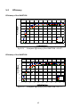
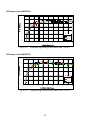
5.2 EFFICIENCY....................................................................................................... 62
5.3
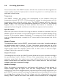
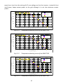
DE‐RATING
OPERATION .................................................................................... 64
5.4
MAINTENANCE ................................................................................................ 67
5.4.1
Exchange
of
the
GFDI
Fuse ................................................................ 67
5.4.2
Factory
Service.................................................................................... 68
5.4.2.1
Remove
the
Inverter .......................................................................... 69
5.4.2.2
Re‐install
the
Inverter ........................................................................ 74
7
List
of
Figures
Fig1.1.1
Grid
Connected
Solar
System
Overview .................................................. 10
Fig
2.1.1 Clearances
required
for
ISMGT1
inverter
installation.......................... 18
Fig
2.2.1 Removal
of
the
mounting
bracket
from
the
inverter ........................... 19
Fig
2.2.2 Inverter
mounting
bracket ..................................................................... 20
Fig
2.2.3 Fasten
the
mounting
bracket................................................................. 21
Fig
2.2.4 Hook
the
Inverter
on
the
mounting
bracket
and
then
fasten
the
screw23
Fig
2.3.1 Wiring
box
type....................................................................................... 24
Fig
2.3.2 Turn
the
DC/AC
disconnect
switch
OFF ................................................. 25
Fig
2.3.3 Remove
the
cover
of
the
wiring
box ...................................................... 25
Fig
2.3.4 Sealing
pins
(plugs)................................................................................. 26
Fig
2.3.5 Wiring
box
front
view ............................................................................. 27
Fig
2.3.1.1 AC
Terminal
Block
for
AC
cable
connections ........................................ 29
Fig
2.3.2.1 PV‐
terminal
connection ........................................................................ 31
Fig
2.3.2.1.1
Negative
Ground
Setting
and
DC
wires
connections ........................... 33
Fig
2.3.2.1.2
DC
terminal
blocks
for
DC
cable
connection
in
Negative
Ground33
Fig
2.3.2.2.1
Positive
Ground
Setting
and
DC
wire
connections....................... 35
Fig
2.3.2.2.2
DC
terminal
blocks
for
DC
cable
connection
in
Positive
Ground35
Fig
2.3.3.1 Positions
of
the
communication
ports
and
termination
switch .......... 37
Fig
2.3.3.3 RS‐232
connection.................................................................................. 38
Fig
2.3.3.4 RS‐485
connection.................................................................................. 39
Fig
2.4.1 Parallel
configuration
of
inverter .......................................................... 40
Fig
3.3.1 Front
panel
of
the
ISMGT1
inverter....................................................... 44
Fig
3.4.1 ISMGT1
inverter
LCD
display
lay‐out ..................................................... 54
Fig
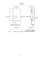
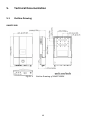
5.1.2 Outline
Drawing
of
ISMGT128DS........................................................... 60
Fig
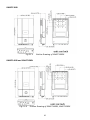
5.1.5 Outline
Drawing
of
ISMGT138DS........................................................... 61
Fig
5.1.8 Outline
Drawing
of
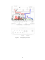
ISMGT140DS,
ISMGT150DS................................... 61
Fig
5.2.1 European
Efficiency
of
the
ISMGT128
=
95.4
%.................................... 62
Fig
5.2.2 European
Efficiency
of
the
ISMGT138
=
95.7
%.................................... 62
Fig
5.2.3 European
Efficiency
of
the
ISMGT140
=
95.8
%.................................... 63
Fig
5.2.4 European
Efficiency
of
the
ISMGT150
=
95.8
%.................................... 63
Fig
5.3.1 Temperature
derating
curve
of
the
ISMGT128..................................... 65
Fig
5.3.2 Temperature
derating
curve
of
the
ISMGT138..................................... 65
Fig
5.3.3 Temperature
derating
curve
of
the
ISMGT140..................................... 65
Fig
5.3.4 Temperature
derating
curve
of
the
ISMGT150..................................... 66
Fig
5.4.1.1 Open
the
cap
of
the
GFDI
fuse
holder................................................... 67
Fig
5.4.2.1.1
Remove
the
cover
of
the
Inverter................................................ 69
Fig
5.4.2.1.2
Remove
the
DC
and
AC
wires ...................................................... 70
Fig
5.4.2.1.3
Keep
the
well‐wrapped
DC
and
AC
wires
in
store
in
the
wiring
box ... 70
Fig
5.4.2.1.4
Remove
the
screws
and
nuts
bonding
between
the
inverter
and
wiring
box.…………………………………………………………………………………………………………………….71
8
Fig
5.4.2.1.5
Un‐hang
the
inverter
carefully .............................................................. 71
Fig
5.4.2.1.6
Locate
the
cover
plate
in
place
and
fasten
the
screws ........................ 72
Fig
5.4.2.2.1
Re‐install
the
cover
plate
and
fix
it
on
the
top
of
the
wiring
box74
Fig
5.4.2.2.2
Hang
the
inverter
onto
the
mounting
bracket
carefully ................... 74
Fig
5.4.2.2.3
Fasten
the
screws
and
nuts
bonding
between
the
inverter
and
the
wiring
box
for
its
construction
and
grounding
continuità......................................... 75
Fig
5.4.2.2.4
Connect
the
AC
wirings
to
their
correct
terminals
individually. 75
Fig
5.4.2.2.5
Fasten
the
screws
of
cover
of
the
inverter
first
and
the
wiring
box
then……………………… ..................................................................................................... 76
9
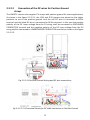
1.
Introduction
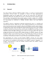
1.1
General
The
Carlo
Gavazzi
Industries
ISMGT1
product
family
is
a
series
of
grid‐connected
photovoltaic
inverters
which
are
designed
to
convert
DC
power
generated
by
photovoltaic
arrays
into
AC
power
that
is
fed
into
the
utility
grid.
The
ISMGT128,
ISMGT138,
ISMGT140,
and
ISMGT150
are
part
of
the
family
for
the
European
market.
The
overview
of
the
grid‐tied
solar
energy
system
is
shown
in
figure
1.1.1.
ISMGT1
inverters
utilize
state‐of‐the‐art
technology,
reliability
and
ease
of
use
and
comply
with
the
requirements
of
VDE0126‐1‐1,
DK5940,
RD1663,
RD661,
G.83
and
EN50178
regulation.
The
ISMGT1
inverter
is
designed
to
operate
automatically
once
it
is
installed
and
commissioned
correctly.
When
the
DC
input
voltage
generated
by
the
photovoltaic
array
rises
above
the
pre‐set
threshold
value,
the
embedded
controller
starts
and
goes
through
System
Check
mode
and
then
into
Monitoring
mode
until
the
PV
Start
Voltage
is
reached.
During
this
time,
the
ISMGT1
inverter
will
not
generate
AC
power.
Once
all
conditions
necessary
for
grid
connection
are
satisfied,
the
ISMGT1
inverter
goes
into
the
Grid/MPP
mode
and
begins
feeding
the
AC
power
into
the
grid.
When
the
input
DC
voltage
falls
below
the
minimum
MPP
voltage
setting,
the
ISMGT1
inverter
will
stop
feeding
AC
power
into
the
grid
and
return
to
monitoring
mode.
Should
the
input
DC
voltage
rise
again
above
the
PV
Start
Voltage,
and
all
conditions
necessary
for
grid
connection
are
satisfied,
the
ISMGT1
inverter
will
enter
the
Grid/MPP
mode
again.
We
appreciated
your
choice
of
Carlo
Gavazzi
ISMGT1
inverters
for
your
power
conversion
devices
in
your
solar
power
system.
This
document
contains
the
information
you
need
for
the
installation
and
settings
of
the
ISMGT1
inverters.
Therefore,
it
is
strongly
recommended
to
read
this
manual
carefully
before
the
ISMGT1
inverter
installation
and
settings.
Fig1.1.1
Grid
Connected
Solar
System
Overview
10
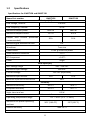
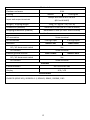
1.2
Specifications
Specifications
for
ISMGT128
and
ISMGT138
Name‐Part
number
ISMGT128
Grid
output
(AC)
Grid
voltage,
nominal
ISMGT138
230
VAC
Grid
frequency,
nominal
50
Hz
Maximum
output
power
2800
W
3800
W
Maximum
output
current
12.2
A
16.6
A
20
A
20
A
Output
over
current
protection
(recommended)
Maximum
grid
backfeed
current
0
A
Waveform
True
sine
Power
factor
>
0.99
@
norminal
power
Total
Harmonic
Distortion
<
3
%
DC
Component
<
0.5
%
Phase
Single
Solar
input
(DC)
MPP
voltage
range
200
~
550
VDC
Maximum
input
voltage
600
VDC
PV
start
voltage
235
VDC
(adjustable)
Maximum
input
current
15
A
20
A
24
A
Maximum
input
short
circuit
current
Efficiency
Maximum
efficiency
96.4
%
96.4
%
European
efficiency
95.4
%
95.7
%
Night‐time
tare
loss
0.5
W
Environmental
Operating
temperature
range
Maximum
full
power
operating
ambient
‐25°
~
+65°C
(‐13°
~
+149°F)
58°C
(136.4°F)
Relative
humidity
55°C
(131°F)
Max.
95
%
11
Mechanical
Outdoor
enclosure
IP44
Cooling
Natural
Cooling
fan
2
Accept
wire
size
of
4
to
16
mm Input
and
output
terminals
(#10
to
#6
AWG)
Weight
/
Shipping
weight
23
kg
/
27
kg
(50.7
lb
/
59.5
lb)
Dimensions
(HxWxD)
768x454x175
mm
(30.3x17.9x6.9
inches)
Shipping
dimensions
(HxWxD)
840x540x275
mm
(33.1x21.3x10.8
inches)
Junction
box
AC
connection
Screw
terminal
DC
connection
Standard
3
strings
input
4
strings
input
ISMGT128D
ISMGT138D
DC
/
AC
disconnect
switch
Yes
DC
connect
Screw
terminal
Positive
ground
inverter
ISMGT128DP
DC
/
AC
disconnect
switch
ISMGT138DP
Yes
DC
connect
Screw
terminal
Interface
Communication
RS‐232
and
RS‐485
Display
LED
/
LCD
Certifications
EN50178
(IEC62103),
VDE0126‐1‐1,
RD1663,
RD661,
DK5940,
G.83
12
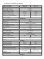
Specifications
for
ISMGT140
and
ISMGT150
Name‐Part
number
ISMGT140
Grid
output
(AC)
Grid
voltage,
nominal
ISMGT150
230
VAC
Grid
frequency,
nominal
50
Hz
Maximum
output
power
4000
W
5000
W
Maximum
output
current
17.4
A
21.8
A
20
A
25
A
Output
over
current
protection
(recommended)
Grid
output
(AC)
Maximum
grid
backfeed
current
0
A
Waveform
True
sine
Power
factor
>
0.99
@
norminal
power
Total
Harmonic
Distortion
<
3
%
DC
Component
<
0.5
%
Phase
Single
Solar
input
(DC)
MPP
voltage
range
200
~
550
VDC
Maximum
input
voltage
600
VDC
PV
start
voltage
235
VDC
(adjustable)
Maximum
input
current
22
A
Maximum
input
short
circuit
25
A
30
A
current
Efficiency
Maximum
efficiency
96.5
%
96.5
%
European
efficiency
95.8
%
95.8
%
Night‐time
tare
loss
0.5
W
Environmental
Operating
temperature
range
Maximum
full
power
operating
ambient
‐25°
~
+65°C
(‐13°
~
+149°F)
58°C
(136.4°F)
Relative
humidity
54°C
(129.2°F)
Max.
95
%
Mechanical
13
Outdoor
enclosure
IP44
Cooling
Cooling
fan
2
Accept
wire
size
of
4
to
16
mm Input
and
output
terminals
(#10
to
#6
AWG)
Weight/Shipping
weight
28
kg
/
32
kg
(61.7
lb
/
70.5
lb)
Dimensions
(HxWxD)
Shipping
dimensions
(HxWxD)
768x454x210
mm
(30.3x17.9x8.3
inches)
840x548x305
mm
(33.1x21.6x12
inches)
Junction
box
AC
connection
Screw
terminal
DC
connection
4
strings
input
Standard
ISMGT140D
DC/AC
disconnect
switch
ISMGT150D
Yes
DC
connect
Screw
terminal
Positive
ground
inverter
ISMGT140DP
DC/AC
disconnect
switch
ISMGT150DP
Yes
DC
connect
Screw
terminal
Interface
Communication
RS‐232
and
RS‐485
Display
LED
/
LCD
Certifications
EN50178
(IEC62103),
VDE0126‐1‐1,
RD1663,
RD661,
DK5940,
G.83
14
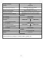
1.3
Adjustable
Parameter
Settings
This
new
series
of
ISMGT1
inverters
have,
currently
four
different
interface
protections
in
order
to
fulfill
the
market
needs
most
of
European
countries.
They
can
be
distinguished
by
the
model
names
described
as
follows.
Some
models
have
the
same
interface
protection
but
differ
in
the
display
and
documentation
language
(
Eg.
DE
and
FR,
interface
is
VDE0126
for
both
but
DE
has
German
documentation
and
Display
language
whilst
FR
is
French):
•
ISMGT1xxD‐DE
•
ISMGT1xxD‐ES
•
ISMGT1xxD‐EN
•
ISMGT1xxD‐FR
•
ISMGT1xxD‐IT
•
ISMGT1xxD‐UK
:
For
Germany
:
For
Spain
:
European
version
:
For
France
:
For
Italy
:
For
United
Kingdom
Interface
Parameter
Settings
recommendation
VDE0126‐1‐1
DK5940
RD1663,
G.83
RD661
ISMGT1xxD‐DE
Model
name/s
ISMGT1xxD‐FR
ISMGT1xxD‐IT
ISMGT1xxD‐ES
ISMGT1xxD‐UK
ISMGT1xxD‐EN
Over‐voltage
(VAC)
260.0
262.0
253.0
264.0
Under‐voltage
(VAC)
190.0
188.0
196.0
207.0
Over‐frequency
(Hz)
50.19
50.3
51.0
50.5
Under‐frequency
(Hz)
47.51
49.7
48.0
47.0
Over‐voltage
clearing
time
(cycle)
8
4
8
74
Under‐voltage
clearing
time
(cycle)
8
9
8
74
Over‐frequency
clearing
time
(cycle)
5
3
5
24
Under‐frequency
clearing
time
(cycle)
5
3
5
24
Voltage
quality
monitoring*
(VAC)
253.0
257.6
250.7
260.0
Voltage
quality
monitoring
time*
(s)
300
0
(NA)
0
(NA)
0
(NA)
Reconnect
delay
(s)
20
20
180
180
235.0
235.0
235.0
235.0
PV
start
voltage
(VDC)
*
The
period
of
time
for
the
ISMGT1
inverter
to
disconnect
from
the
grid
and
enter
the
Monitoring
mode
after
the
detection
of
the
AC
voltage
that
is
higher
than
the
Voltage
quality
monitoring
setting
and
below
the
Over‐voltage
setting.
This
function
is
available
only
in
the
models
of
Germany
type
according
to
the
VDE
0126‐1‐1,
Clause
4.2.3.
15
1.4
Accessories
•
Operation
Manual
•
Auto‐Test
software
CD
(ISMGT1xxxx‐IT
only)
16
1
pc
1
pc
2.
Installation
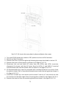
2.1
Placement
1.
ISMGT1
inverters
must
be
mounted
vertically,
may
be
located
indoor
or
outdoor,
according
to
protection
class
IP44.
2.
Leave
at
least
50
cm
(19.67
inches)
of
free
space
above
and
100
cm
(39.37
inches)
below
the
inverter
when
installed
outdoor.
Allow
20
cm
(7.87
inches)
between
inverters
when
installing
multiple
inverters
for
better
ventilation
(see
figure
2.1.1).
3.
Mount
the
inverter
on
a
wall
that
is
strong
enough
to
sustain
the
inverter:
32
kg
(70.5
lb)
weight.
4.
Avoid
mounting
the
inverter
on
a
location
directly
exposed
to
sunlight
to
maintain
the
ambient
temperature
of
the
inverter
within
‐25°C
and
65°C
(‐13°F
and
149°F).
Humidity
shall
be
within
0%
and
95%.
5.
Keep
DC
wiring
as
short
as
possible
to
minimize
power
loss.
6.
The
mounting
bracket
should
be
fastened
on
a
concrete
or
a
masonry
wall
with
the
provided
accessory.
WARNING!
Do
not
expose
the
inverter
to
the
corrosive
liquids
and/or
gases.
WARNING!
Not
to
operate
the
inverter
in
flammable
or
explosive
environment,
or
close
to
flammable
materials,
failing
to
so
may
result
in
fire
and
/
or
explosion.
Some
parts
of
the
cooling
surface
can
reach
temperatures
over
70°C
(158°F).
17
Fig
2.1.1
Clearances
required
for
ISMGT1
inverter
installation
18
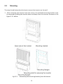
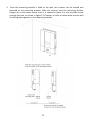
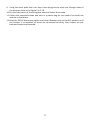
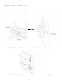
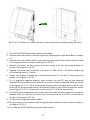
2.2
Mounting
The
steps
listed
below
describe
how
to
mount
the
inverter
on
the
wall:
1.
After
removing
the
inverter
from
the
carton,
the
attached
mounting
bracket
must
be
removed
by
sliding
the
bracket
down
and
away
from
the
inverter
as
shown
in
the
figure
2.2.1
below.
Fig
2.2.1
Removal
of
the
mounting
bracket
from
the
inverter
19
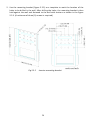
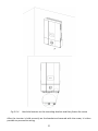
2.
Use
the
mounting
bracket
(figure
2.2.2)
as
a
template
to
mark
the
location
of
the
holes
to
be
drilled
in
the
wall.
After
drilling
the
holes,
the
mounting
bracket
is
then
held
against
the
wall
and
fastened
to
the
wall
with
anchors
as
shown
in
the
figure
2.2.3.
(A
minimum
of
three
(3)
screws
is
required)
Fig
2.2.2
Inverter
mounting
bracket
20
Fig
2.2.3
Fasten
the
mounting
bracket
21
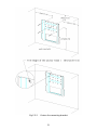
3.
Once
the
mounting
bracket
is
fixed
to
the
wall,
the
inverter
can
be
located
and
fastened
to
the
mounting
bracket.
Slide
the
inverter
over
the
mounting
bracket
flanges
let
it
slide
down
slowly
until
it
is
hooked
in
place.
Put
the
provided
screw
through
the
hole,
as
shown
in
figure
2.2.4
below,
in
order
to
fasten
both
inverter
and
the
wiring
box
together
to
the
mounting
bracket.
22
Fig
2.2.4
Hook
the
Inverter
on
the
mounting
bracket
and
then
fasten
the
screw
After
the
inverter
is
held
correctly
on
the
bracket
and
secured
with
the
screw,
it
is
then
possible
to
proceed
to
wiring.
23
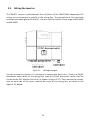
2.3
Wiring
the
inverter
The
ISMGT1
inverter
is
provided
with
four
(4)
(three
(3)
for
ISMGT128)
independent
PV
strings
to
be
connected
in
parallel
in
the
wiring
box.
The
wiring
box
of
the
has
screw
terminals
and
cable
glands
for
the
DC
,
the
wire
section
shall
be
in
the
range
of
#10
AWG
and
#6
AWG.
Fig
2.3.1
Wiring
box
type
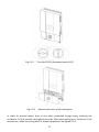
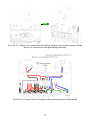
It
order
to
wire
the
inverter
it
is
necessary
to
remove
the
front
cover.
There
is
a
DC/AC
disconnect
switch
built
on
the
wiring
box,
then
the
DC/AC
disconnect
switch
shall
be
turned
to
the
OFF
position
first
of
all,
as
shown
in
figure
2.3.2.
Then
remove
the
screws,
two
on
each
side
of
the
cover;
remove
the
cover
of
the
wiring
box,
as
shown
in
the
figure
2.3.3
below.
24
Fig
2.3.2
Fig
2.3.3
Turn
the
DC/AC
disconnect
switch
OFF
Remove
the
cover
of
the
wiring
box
In
order
to
prevent
water,
dust
or
any
other
unwanted
foreign
body,
entering
the
enclosure.
All
the
unused
cable
glands
must
be
filled
with
sealing
pins,
enclosed
in
the
accessories,
when
the
wiring
work
is
almost
completed.
See
figure
2.3.4.
25
Fig
2.3.4
Sealing
pins
(plugs)
The
three
following
sections
describe
the
wiring
for
the
AC
ouputs,
DC
inputs,
and
communication
ports.
There
is
one
(1)
AC
terminal
block,
a
pair
of
DC
terminal
blocks
and
two
(2)
RJ‐45
connectors
in
the
wiring
box
as
shown
in
the
figure
2.3.5.
The
AC
terminal
block
is
used
to
connect
to
the
utility
grid
through
a
circuit
breaker
and
distribution
panel
according
to
national
and
local
requirements.
The
DC
terminal
blocks
are
used
to
connect
up
to
4
PV
strings
in
parallel
in
the
wiring
box.
The
RJ‐45
connectors
are
used
for
external
communication
to
a
remote
computer,terminal
or
another
inverter
in
a
Daisy
Chain
type
connection.
26
Fig
2.3.5
Wiring
box
front
view
27
WARNING!
All
electrical
work
shall
be
carried
out
in
compliance
with
the
relevant
electrical
norms,
issued
by
local
distribution
network
operator
(DNO),
and
follow
the
important
safety
instructions
in
this
manual.
WARNING!
Under
the
DNO’s
inspection
authority
a
dedicated
circuit
breaker
must
be
installed
at
the
connection
to
the
AC
mains.
WARNING!
Make
sure
that
suitable
connecting
cables
are
used
for
both
the
AC
and
DC
wirings.
The
cables
must
be
choosen
considering
the
Current
capacity,
weatherproof
and
immune
to
temperature
fluctuations
and
UV
radiations,
etc.
Use
#10
AWG
to
#6
AWG,
90°C
(194°F)
copper
wire
for
all
AC
and
DC
wiring
connections
to
the
ISMGT1
inverter.
WARNING!
PV
arrays
are
energized
when
exposed
to
light.
Cover
the
arrays
with
opaque
(dark)
material
during
installation
and
wiring.
28
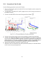
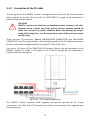
2.3.1 Connection
of
the
AC
cable
Use
the
following
procedure
to
wire
the
AC
cables.
1.
Open
the
Distribution
panel
and
switch
off
the
circuit
breaker
used
to
connect
the
inverter
to
the
grid.
2.
Use
#10
AWG
to
#6
AWG,
90°C
(194°F)
copper
wire
for
all
AC
wiring
connections
to
the
ISMGT1
inverter.
3.
Connect
the
cable
GND
to
the
screw
of
the
ground
bar
labeled
.
Fig
2.3.1.1
AC
Terminal
Block
for
AC
cable
connections
4.
Connect
the
Grid
Phase
cable
to
the
terminal
labeled
L
of
the
AC
terminal
block.
5.
Connect
the
cable
Grid
Neutral
to
the
terminal
labeled
N
(or
Phase
2)
of
the
AC
terminal
block.
NOTE:
the
ISMGT1
inverters
can
also
be
connected
on
a
Utility
Grid
without
Neutral.
In
this
case,
providing
the
Voltage
is
within
the
specified
limit
of
the
Interface
setting,
on
this
terminal
it
is
possible
to
connect
another
Phase
6.
Tighten
the
screws
with
a
torque
of
1.7Nm
(15.6
in‐lb).
7.
Reconfirm
that
all
connections
have
been
performed
properly
as
described
above
and
all
screws
are
properly
tightened.
29
WARNING!
Reconfirm
that
the
circuit
breaker
to
the
main
utility
is
switched
OFF
before
connecting
the
power
cable
from
the
breaker
to
the
AC
terminal
block.
!
CAUTION!
Ensure
that
the
total
impedance
of
the
grid
and
the
interconnected
AC
power
cable
is
less
than
1.25Ω.
WARNING!
According
to
the
relevant
electrical
norms
and
directives,
issued
by
local
distribution
network
operator
(DNO),
each
connection
to
an
ISMGT1
inverter
must
be
installed
with
a
dedicated
double‐pole
circuit
breaker
in
the
main
utility
service
panel.
The
breaker
must
be
sized
to
carry
the
rated
maximum
output
voltage
and
current
of
the
ISMGT1
Inverter.
Refer
to
Section
1.2
Specifications:
Output
over
current
protection,
pages
3~6.
No
other
appliances
shall
be
connected
to
the
circuit
breaker.
30
2.3.2
Connection
of
the
DC
cable
The
wiring
box
of
the
ISMGT1
inverter
is
designed
to
have
pairs
of
DC
terminal
blocks
which
support
up
to
four
(4)
(three
(3)
for
ISMGT128)
PV
strings
to
be
connected
in
parallel
inside
the
wiring
box.
!
CAUTION!
ISMGT1
inverters
are
listed
for
no
backfeed
current.
However,
all
other
external
source
circuits
and
array
wiring
Current
capacity
should
be
taken
into
account
by
system
installers
when
determining
the
proper
rating
of
PV
string
fuse,
or
a
fire
hazard
may
occur
if
there
is
short‐circuit
in
a
PV
string.
There
are
two
(2)
terminals,
labeled
UNGROUNDED
CONDUCTOR
and
GROUNDED
CONDUCTOR,
per
PV
string
located
in
the
wiring
box
used
for
the
DC
cable
connections.
All
the
screws
shall
be
tightened
with
a
torque
of
1.7Nm
(15.6
in‐lb).
Up
to
four
(4)
(three
(3)
for
ISMGT128)
PV
strings
(4
pairs)
can
be
connected
to
the
ISMGT1
inverter
as
shown
in
the
figure
2.3.2.1.
The
PV
strings
will
be
connected
in
parallel
inside
the
wiring
box.
Fig
2.3.2.1
PV‐
terminal
connection
The
ISMGT1
inverter
supports
both
negative
and
positive
ground
for
PV
strings
connections.
The
JP14
and
JP15
jumpers
are
used
for
the
settings
of
the
negative
and
positive
ground.
31
CAUTION!
!
PV
arrays
provide
Energy
when
exposed
to
light,
they
supplì
very
high
DC
voltage.
Make
sure
safe
working
practices
are
followed.
WARNING!
Route
the
DC
connection
cables
to
the
ISMGT1
inverters
away
from
any
possible
hazard
that
could
damage
the
cables.
WARNING!
Hazardous
voltage
is
still
present
on
the
device
after
disconnection
of
all
PV
DC
inputs.
Allow
5
minutes
for
the
inverter
to
completely
discharge
the
energy
stored
in
capacitors.
32
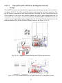
2.3.2.1
Connection
of
the
DC
wires
for
Negative
Ground
Arrays
The
ISMGT1
inverters
are
shipped
with
negative
ground
setting,
they
are
set
as
shown
in
the
figure
2.3.2.1.1.
The
JP14
and
JP15
jumpers
are
placed
on
the
lower
positions.
The
red
DC
wire
is
connected
to
the
DCIN+
terminal,
the
black
DC
wire
is
connected
to
the
DCIN‐
terminal.
In
this
case
the
positive
polarity
of
the
DC
input
voltage
from
the
PV
string
shall
be
connected
to
the
terminal
labeled
UNGROUNDED
CONDUCTOR
and
the
negative
polarity
of
the
DC
input
voltage
from
the
PV
string
shall
be
connected
to
the
terminal
labeled
GROUNDED
CONDUCTOR
as
shown
in
the
figure
2.3.2.1.2.
Fig
2.3.2.1.1
Negative
Ground
Setting
and
DC
wires
connections
Fig
2.3.2.1.2
DC
terminal
blocks
for
DC
cable
connection
in
Negative
Ground
33
!
CAUTION!
Identify
the
different
polarity
of
DC
voltage
on
each
PV
string
and
connect
respectively
to
the
input
terminals
marked
“UNGROUNDED
CONDUCTOR”
and
“GROUNDED
CONDUCTOR”.
Make
sure
the
DC
voltage
that
PV
arrays
generate
is
equal
to
or
less
than
600
VDC
in
any
case.
•
The
“+”
cable
of
the
DC
input
voltage
shall
be
connected
to
the
terminal
labeled
UNGROUNDED
CONDUCTOR
and
the
“‐”
cable
of
the
DC
input
voltage
shall
be
connected
to
the
terminal
labeled
GROUNDED
CONDUCTOR.
•
Avoid
using
wire
nuts
to
join
any
wire
together
or
to
make
any
improper
junction
anywhere
in
the
PV
system.
Wire
nuts
are
frequent
cause
of
unreliable
connections,
resistive
connections,
and
ground
faults.
•
Tighten
the
screws
with
a
torque
of
1.7Nm
(15.6
in‐lb).
34
2.3.2.2
Connection
of
the
DC
wires
for
Positive
Ground
Arrays
The
ISMGT1
inverter
also
support
PV
arrays
with
positive
ground
for
some
applications.
As
shown
in
the
figure
2.3.2.2.1,
the
JP14
and
JP15
jumpers
are
placed
on
the
higher
positions
to
set
to
the
positive
ground.
And
the
red
DC
wire
is
connected
to
DCIN‐
terminal
and
the
black
DC
wire
is
connected
to
DCIN+
terminal.
In
this
case
the
positive
polarity
of
the
DC
input
voltage
from
the
PV
string
shall
be
connected
to
GROUNDED
CONDUCTOR
terminal
and
the
negative
polarity
of
the
DC
input
voltage
from
the
PV
string
shall
be
connected
to
UNGROUNDED
CONDUCTOR
terminal
as
shown
in
the
figure
2.3.2.2.2.
Fig
2.3.2.2.1Positive
Ground
Setting
and
DC
wire
connections
Fig
2.3.2.2.2
DC
terminal
blocks
for
DC
cable
connection
in
Positive
Ground
35
CAUTION!
The
Positive
Polarities
of
the
DC
input
voltage
from
a
PV
string
shall
be
correctly
connected
to
the
“GROUNDED
CONDUCTOR”
terminal
and
the
Negative
Polarity
of
the
DC
input
voltage
from
a
PV
string
shall
be
connected
to
the
“UNGROUNDED
CONDUCTOR”
terminal.
Make
sure
the
DC
voltage
that
PV
arrays
generate
is
equal
to
or
less
than
600
VDC
in
any
case.
•
The
“+”
cable
of
the
DC
input
voltage
shall
be
connected
to
the
terminal
labeled
“GROUNDED
CONDUCTOR”
and
the
“‐”
cable
of
the
DC
input
voltage
shall
be
connected
to
the
terminal
labeled
“UNGROUNDED
CONDUCTOR”.
•
Avoid
using
wire
nuts
to
join
any
wires
together
or
to
make
any
improper
junction
anywhere
in
the
PV
system.
Wire
nuts
are
a
frequent
cause
of
unreliable
connections,
resistive
connections,
and
ground
faults.
•
Tighten
the
screws
with
a
torque
of
1.7Nm
(15.6
in‐lb).
!
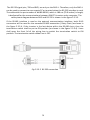
36
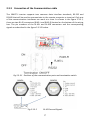
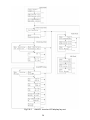
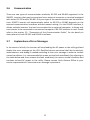
2.3.3
Connection
of
the
Communication
cable
The
ISMGT1
inverter
supports
two
common
data
interface
standards,
RS‐232
and
RS‐485
that
will
be
used
to
communicate
to
the
remote
computer
or
terminal.
Only
one
of
the
communication
interfaces
can
work
at
a
time.
As
shown
in
the
figure
2.3.3.1,
there
are
two
RJ‐45
connectors
(RJ45‐L
and
RJ45‐R)
located
on
the
bottom
of
the
wiring
box.
The
pin
numbers
of
the
RJ‐45L
and
RJ‐45R
connectors
and
the
corresponding
signals
are
described
in
the
figure
2.3.3.2
below.
Fig
2.3.3.1
Positions
of
the
communication
ports
and
termination
switch
Fig
2.3.3.2
RJ‐45
Pins
and
Signals
37
The
RS‐232
signal
pins,
TXD
and
RXD,
are
only
on
the
RJ45‐L.
Therefore,
only
the
RJ45‐L
can
be
used
to
connect
to
one
remote
PC
or
terminal
when
the
RS‐232
interface
is
used.
The
cable
with
the
part
number
of
WABG‐0918S,
which
is
180
cm
(70.9
inches)
in
length,
is
dedicated
for
the
communications
between
ISMGT1
inverter
and
a
computer.
The
cable
pinout
diagram
between
RJ45
and
RS‐232
is
shown
in
the
figure
2.3.3.3.
If
the
RS‐485
interface
is
used
as
the
external
communication
interface,
both
RJ‐45
connectors
will
be
used
for
the
cascaded
RS‐485
connection
(
Daisy
Chain)
as
shown
in
the
figure
2.3.3.4.
If
the
inverter
is
the
last
device
within
the
RS‐485
chain,
then
the
termination
switch
shall
be
put
to
ON
position
(as
shown
in
the
figure
2.3.3.4).
Users
shall
open
the
front
lid
of
the
wiring
box
to
switch
the
termination
switch
to
ON
position.
The
termination
switch
default
set
is
OFF.
Fig
2.3.3.3
RS‐232
connection
38
Fig
2.3.3.4
RS‐485
connection
39
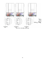
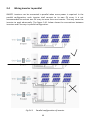
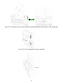
2.4
Wiring
inverter
in
parallel
ISMGT1
inverters
can
be
connected
in
parallel
when
more
power
is
required.
In
the
parallel
configuration,
each
inverter
shall
connect
to
its
own
PV
array.
It
is
not
recommended
to
connect
one
PV
array
to
more
than
one
inverter.
This
may
cause
the
inverter
to
work
abnormally.
The
figure
2.4.1
below
shows
the
connections
between
inverters
and
PV
arrays
in
parallel
configuration.
Fig
2.4.1
Parallel
configuration
of
inverter
40
3.
Operation
3.1
Overview
The
ISMGT1
inverter
will
operate
automatically.
Once
the
irradiation
is
strong
enough
to
generate
DC
input
voltage
over
the
pre‐set
threshold
value,
the
inverter
turns
on.
The
inverter
feeds
power
into
the
grid
after
input
voltage
rises
over
the
PV
start
voltage
and
all
necessary
conditions
are
checked
and
fulfilled.
The
inverter
goes
into
Monitoring
mode
from
the
Grid/MPP
mode
if
the
DC
input
voltage
goes
under
the
minimum
MPP
voltage.
If
the
DC
input
voltage
falls
below
the
pre‐set
threshold
value,
the
inverter
will
shut
down
itself.
There
are
five
main
operating
modes
as
described
in
detail
below.
System
Check
:
When
the
DC
input
voltage
goes
above
the
PV
start
voltage,
the
inverter
is
powered‐up,
initialises,
and
then
enters
the
System
Check
mode.
In
this
operating
mode,
the
inverter
runs
the
diagnostic
routine.
This
stage
lasts
a
few
seconds.
Monitoring
:
After
System
Checking
is
complete
the
inverter
enters
the
Monitoring
mode.
In
this
operating
mode,
the
inverter
monitors
all
parameters
on
both
AC
and
DC
sides
in
order
to
ensure
that
connecting
to
the
Grid
is
safe.
All
conditions
must
be
fulfilled
and
last
for
the
specified
period
of
time,
then
the
system
will
enter
the
Grid/MPP
mode.
Grid/MPP
Fault
:
After
the
Monitoring
mode,
the
ISMGT1
inverter
confirms
that
all
conditions
necessary
for
feeding
the
power
into
the
utility
grid
are
fulfilled.
The
inverter
will
turn
on
the
AC
relays
and
start
feeding
the
AC
power
to
the
grid.
In
this
operating
mode,
the
inverter
continues
to
convert
the
DC
power
generated
by
the
PV
array
to
the
AC
power
that
is
then
fed
into
the
grid.
:
When
fault(s)
occurs
and
have
been
detected
in
the
operating
mode
described
above,
the
inverter
will
terminate
the
present
state,
stop
feeding
power
to
the
grid,
and
then
jump
into
the
Fault
mode
and
execute
the
programmed
sequence.
In
case
the
faults
clear
for
the
preset
time,
the
inverter
will
leave
Fault
mode
and
enter
System
Check
mode.
Some
faults,
like
component
failure,
will
cause
the
inverter
to
go
into
Idle
mode.
This
Mode
requires
authorised
service
staff
to
clear
the
error(s).
41
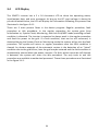
Idle
:
The
inverter
jumps
into
this
operating
mode
when
it
detects
a
major
malfunction
and
will
stop
feeding
the
power
to
the
grid
for
safety
reason.
This
failure
cannot
be
reset
by
anyone
on
field.
Only
authorised
personnel
is
equipped
to
analise
the
failure
and
put
the
system
back
to
operation.
42
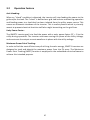
3.2
Operation
Feature
Anti‐Islanding:
When
an
“island”
condition
is
detected,
the
inverter
will
stop
feeding
the
power
to
the
grid
and/or
the
load.
The
“island”
is
defined
as
a
grid
tied
inverter
maintaining
operation
and
feeding
power
to
a
load
that
has
been
isolated
from
the
utility
power
source.
This
causes
an
automatic
shutdown
of
the
inverter.
This
is
a
safety
feature
which
is
primarily
meant
to
prevent
electrical
shock
to
staff
who
might
be
working
on
the
grid
lines.
Unity
Power
Factor:
The
ISMGT1
inverter
goal
is
to
feed
the
power
with
a
unity
power
factor
(PF
=
1)
to
the
utility
during
operation.
The
inverter
continues
sensing
the
phase
of
the
utility
voltage,
and
constructs
the
output
current
waveform
in
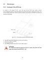
phase
with
the
utility
voltage.
Maximum
Power
Point
Tracking:
In
order
to
find
the
most
efficient
way
of
utilizing
the
solar
energy,
ISMGT1
inverters
are
designed
to
track
and
absorb
the
maximum
power
from
the
PV
array.
The
Maximum
Power
Point
Tracking
(MPPT)
function
is
employed
in
the
embedded
control
software
to
achieve
this
intended
purpose.
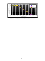
43
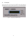
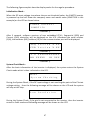
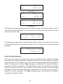
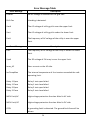
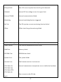
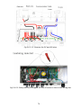
3.3
LED
Indication
There
are
three
LED’s
on
the
front
panel
of
the
ISMGT1
inverter
which
displays
the
operating
status
of
the
inverter.
As
shown
in
the
figure
3.3.1.
The
detailed
explanations
of
the
status
and
the
corresponding
LED
indications
are
described
in
the
following
table.
Fig
3.3.1
Front
panel
of
the
ISMGT1
inverter
44
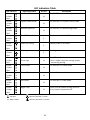
LED
Indication
Table
LED
indicators
Green
Yellow
Red
Green
Yellow
Red
Green
Yellow
Red
Green
Yellow
Red
Green
Yellow
Red
Green
Yellow
Red
Green
Yellow
Red
Green
Yellow
Red
Green
Yellow
Red
Green
Yellow
Red
Green
Yellow
Red
Operating
status
Initialization
N
Description
The
ISMGT1
inverter
is
in
initial
mode.
N
The
inverter
is
in
System
Check
mode.
N
The
inverter
is
in
Monitoring
mode.
Y
The
inverter
is
in
Grid/MPP
mode.
Y
Output
power
is
de‐rated.
On
Grid
System
Check
mode
Monitoring
mode
Grid/MPP
mode
Power
De‐rating
Warning
Warning
detection.
Y
1.Low
Insolation
2.Vac
high
N
1.Insufficient
Sun
irradiation.
2.Vac
is
higher
than
the
voltage
quality
monitoring
setting.
The
inverter
is
in
Fault
mode.
N
Ground
fault
detected.
N
The
inverter
is
in
Idle
mode.
N
There
is
no
DC
power
coming
from
PV
array.
System
is
powered
off.
N
Fault
mode
Ground
Fault
Idle
mode
Night
Time
:
LED
ON
:
LED
ON
/
OFF
0.1
/
0.9
Sec
:
LED
OFF
:
LED
ON
/
OFF
0.9
/
0.1
Sec
:
LED
ON
/
OFF
0.25
/
0.25
Sec
:
DON’T
CARE
45
3.4
LCD
Display
The
ISMGT1
inverter
has
a
2
x
16
characters
LCD
to
show
the
operating
status,
input/output
data,
and
error
messages.
As
long
as
the
DC
input
voltage
is
above
the
pre‐set
threshold
value,
the
LCD
will
display
the
information
following
the
process
flow
illustrated
in
the
figure
3.4.1.
There
are
3
main
process
flows
in
the
device
program:
Regular
procedure,
fault
procedure
or
idle
procedure.
In
the
regular
procedure
the
system
goes
from
Initialisation
to,
System
Check,
Monitoring,
and
then
Grid/MPP
mode
providing
no
fault
condition
is
detected.
The
inverter
is
expected
to
always
work
in
the
regular
procedure
and
feed
the
power
to
the
grid.
If
a
fault
condition,
that
can
be
self
recovered,
is
detected
during
the
System
Check
or
Monitoring
mode
the
system
will
go
into
the
fault
procedure.
The
system
will
return
to
regular
procedure
once
the
fault
condition
is
cleared.
An
obvious
example
of
the
automatic
restore
is
the
detection
of
an
“island”
condition
due
to
the
grid
failure,
later
the
grid
may
be
restored
and
the
fault
condition
is
automatically
cleared
when
the
power
recovers.
If
a
fault,
which
cannot
be
self
cleared,
is
detected,
the
system
will
enter
the
idle
procedure.
The
only
tools
to
exit
this
procedure
are
available
to
authorised
personnel.
These
three
procedures
are
illustrated
in
the
figure
3.4.1.
46
The
following
figures
explain
how
the
display
works
for
the
regular
procedure.
Initialisation
Mode
:
When
the
DC
input
voltage
rises
above
the
pre‐set
threshold
value,
the
ISMGT1
inverter
is
powered
up
and
will
show
the
company
name
and
model
name
(ISMGT150
in
this
example)
on
the
LCD
as
shown
below.
CAR LO
GA VA Z Z I
I S MG T 1 5 0
3
seconds
↓
After
3
seconds,
software
versions
of
two
embedded
CPU’s,
Sequential
(SEQ)
and
Current
(CUR)
controller,
will
be
displayed
on
the
LCD.
Afterward
the
serial
number
(S/N),
the
baudrate
(BR)
/
address
(ID)
for
the
communication
port
will
be
displayed.
S EQ
Ve r s i o n
X . XX
CUR
Ve r s i o n
X . XX
3
seconds
↓
S / N
BR
XXXXXXXXXXXX
XXXXX
ID
XXX
3
seconds
↓
System
Check
Mode
:
After
the
basic
information
of
the
inverter
is
displayed,
the
system
enters
the
System
Check
mode
which
is
then
indicated
on
the
LCD.
Mo d e
S y s t em
Ch e c k i n g
During
the
System
Check,
if
the
DC
input
voltage
is
not
reaching
the
point
of
the
PV
start
voltage
setting,
,
then
the
following
message
will
be
shown
on
the
LCD
and
the
system
will
stay
at
this
step.
L ow
I n s o l a t i o n
During
the
System
Check,
if
the
grid
is
not
connected
to
the
inverter,
then
the
inverter
enters
to
Fault
mode
and
following
message
will
be
shown
on
the
LCD.
47
Mo d e
F a u l t
G r i d NA
Monitoring
Mode
:
Once
the
System
Check
is
done,
the
inverter
goes
into
the
Monitoring
mode.
If
all
data
needed
for
grid
feeding
is
in
the
acceptable
range,
the
system
will
keep
monitoring
those
data
for
a
period
of
time.
The
following
information
tell
the
user
that
the
system
will
go
into
the
Grid/MPP
mode
in
XXX
seconds
and
then
show
the
measured
data
of
the
DC
input
voltages
and
the
actual
voltage
and
frequency
on
the
grid
side.
Mo d e
Mo n i t o r i n g
N e x t Co n n e c t
XXX s
3
seconds
↓
Vp v
XXX
V
3
seconds
↓
Va c
XXX . X
F a c
XX . X
V
H z
3
seconds
↓
During
the
Monitoring
mode,
if
DC
input
voltage
falls
under
the
PV
start
voltage
setting,
the
system
stays
in
this
mode
and
shows
the
information
as
follows.
The
system
will
still
keep
measuring
the
parameters
of
both
DC
and
AC
and
display
on
the
LCD.
Mo d e
L ow
Mo n i t o r i n g
I n s o l a t i o n
3
seconds
↓
Vp v
XXX
V
3
seconds
↓
Va c
XXX . X
F a c
XX . X
3
seconds
↓
48
V
H z
For
ISMGT1xxxD‐DE
(Germany
type),
for
instance
which
is
set
according
to
VDE0126‐1‐1,
if
the
AC
voltage
on
the
grid
side
increases
over
the
voltage
quality
monitoring
setting
and
below
the
over
voltage
setting
for
at
last
300
seconds
in
grid/MPP
mode,
the
ISMGT1
inverter
shall
return
to
Monitoring
mode
and
display
the
messages
on
the
LCD
as
shown
below.
If
the
AC
voltage
decreases
and
below
the
voltage
quality
monitoring
setting
for
at
last
300
seconds,
ISMGT1
inverter
will
then
go
back
to
regular
procedure
and
re‐connect
to
the
grid
if
all
conditions
are
satisfied.
Mo d e
Va c
Mo n i t o r i n g
H i g h
3
seconds
↓
Vp v
XXX
V
3
seconds
↓
Va c
XXX . X
F a c
XX . X
3
seconds
↓
V
H z
Grid/MPP
Mode
:
After
the
system
enters
the
Grid/MPP
mode,
it
will
show
the
following
information
in
order
and
repeatedly
until
the
system
goes
to
other
operating
mode.
The
first
screen
shows
the
current
operation
mode.
Mo d e
G r i d / MP P
3
seconds
↓
Next
messages
are
the
actual
real
time
data
of
the
input
/
output
voltage
and
power.
The
first
2
lines
screen
are
for
the
PV
arrays
and
the
following
screens
are
for
the
output.
Vpv
is
the
incoming
voltage
from
PV
array.
Wpv
is
the
incoming
power
of
PV
array
in
Watts.
Vac,
Pac,
Iac,
and
Fac
are:
Voltage,
Power,
Current,
and
Frequency
that
the
inverter
is
feeding
to
the
grid.
49
Vp v
XXX
V
Wp v
XXXX
W
3
seconds
↓
Va c
XXX . X
V
P a c
XXXX
W
3
seconds
↓
F a c
XX . X
H z
I a c
XX . X
A
3
seconds
↓
The
following
message
shows
the
daily
cumulated
energy
in
kWh
and
period
of
time
in
hours
for
the
power
delivered
to
the
grid
since
the
inverter
has
been
powered
on
and
operated
for
current
day.
E t o d a y
XXX . X
H t o d a y
XX . X
k Wh
H r
3
seconds
↓
The
following
message
shows
the
cumulated
energy
in
kWh
and
period
of
time
in
hours
for
the
power
delivered
to
the
grid
up‐to‐date
since
the
inverter
has
been
installed
and
operated.
E a c
H
XXXXXX . X
XXXXX
3
seconds
↓
k Wh
H r
Power
De‐Rating
Message
:
There
are
five
possible
de‐rating
causes,
each
one
displayed
with
a
different
message
when
power
de‐rating
is
detected
in
Grid/MPP
mode.
Only
one
derating
cause
could
be
detected
at
the
time.
Therefore,
only
one
of
the
following
messages
will
be
displayed
if
power
de‐rating
occurs.
When
Temp
message
is
presented,
the
power
de‐rating
is
caused
by
the
over
temperature.
The
Ipv
message
shows
that
the
power
de‐rating
is
caused
by
restricting
the
DC
input
current
to
the
maximum
limit.
The
Iac
and
Pac
messages
illustrate
the
power
de‐rating
is
caused
due
to
restriction
of
the
maximum
output
AC
current
and
power.
The
VacH
message
shows
that
the
power
de‐rating
is
caused
by
the
high
AC
voltage.
50
Mo d e
De r a t i n g
T emp
Mo d e
De r a t i n g
I p v
Mo d e
De r a t i n g
I a c
Mo d e
De r a t i n g
P a c
Mo d e
De r a t i n g
Va cH
Warning
Message
:
There
are
three
possible
warning
messages
which
can
be
shown
when
situations
occur
in
grid
feeding
mode.
When
EEPROM
message
displayed,
the
system
has
encountered
a
failure
accessing
to
the
EEPROM.
The
COMM
message,
represents
failure
of
the
communication
function.
For
the
FAN
BLOCK
message,
shows
that
the
fan
has
stopped
running.
These
warnings
could
be
happening
simultaneously.
Wa r n i n g
E E P R OM
Wa r n i n g
C O MM
Wa r n i n g
F AN
BLOCK
Fault
Mode
:
The
fault
messages
are
described
as
follows.
First
screen
shows
the
mode
fault,
serial
number
of
the
inverter,
the
follows
software
versions
of
the
sequential
(SEQ)
and
current
(CUR)
controllers
and
then
the
error
messages
which
are
listed
in
the
Error
Message
Table
on
section
3.7.
51
Mo d e
S / N
F a u l t
XXXXXXXXXXXX
3
seconds
↓
S EQ
Ve r s i o n
CUR
Ve r s i o n
X . XX
X
X . XX
3
seconds
↓
Mo d e
E r r o r
F a u l t
Me s s a g e
3
seconds
↓
There
are
several
error
messages
which
show
the
detailed
conditions
causing
the
system
going
into
the
Fault
mode.
Such
as
the
messages
shown
below
which
describe
that
the
frequency
on
AC
grid
is
too
high
(H)
or
too
low
(L).
And
after
three
(3)
seconds,
the
message
shows
the
present
frequency
and
the
frequency
that
caused
the
system
to
go
into
Fault
mode.
Mo d e
F a u l t
F a cX
X:
H
or
L
3
seconds
↓
T r i p
a t
XX . XH z
P r e s e n t
XX . XH z
3
seconds
↓
The
message
below
shows
the
AC
voltage
is
too
high
(H)
or
too
low
(L).
And
after
three
(3)
seconds,
the
message
shows
the
present
voltage
and
the
voltage
that
caused
the
system
to
go
into
fault
mode.
Mo d e
F a u l t
Va cX
X:
H
or
L
3
seconds
↓
a t
XXX . XV
P r e s e n t
T r i p
XXX . XV
3
seconds
↓
The
message
below
shows
the
PV
input
voltage
is
too
high.
52
Mo d e
F a u l t
Vp vH
3
seconds
↓
T r i p
a t
XXX . XV
P r e s e n t
XXX . XV
3
seconds
↓
Idle
Mode
:
The
messages
for
Idle
mode
are
as
here
after
described.
First
screen
shows
the
operating
mode
and
serial
number
of
the
inverter,
then
follow
the
software
versions
of
the
sequential
(SEQ)
and
current
(CUR)
controllers
and
then
the
error
messages
which
are
listed
in
the
Error
Message
Table
on
section
3.7.
Mo d e
S / N
I d l e
XXXXXXXXXXXX
3
seconds
↓
S EQ
Ve r s i o n
CUR
Ve r s i o n
X . XX
X
X . XX
3
seconds
↓
Mo d e
E r r o r
I d l e
Me s s a g e
3
seconds
↓
53
Fig
3.4.1
ISMGT1
inverter
LCD
display
lay‐out
54
3.6
Communication
There
are
two
types
of
communication
methods,
RS‐232
and
RS‐485
supported
in
the
ISMGT1
inverters
that
may
be
connected
to
an
external
computer
or
terminal
equipped
with
either
RS‐232
and/or
RS‐485.
Only
one
type
of
the
communication
can
be
used
at
a
time.
ISMGT1
inverter
will
automatically
switch
to
RS‐232
or
RS‐485
depends
on
the
external
communication
interfaces
without
manual
setting.
For
the
RS‐485
interface,
it
allows
multiple
inverters
that
can
be
connected
to
an
external
computer.
It
allows
only
one
inverter
to
be
connected
to
an
external
computer
if
RS‐232
interface
is
used.
Please
refer
to
the
section
2.3,
“Connection
of
the
Communication
Cable”,
for
the
detail
pin
descriptions
for
both
RS‐232
and
RS‐485
interfaces.
3.7
Explanations
of
Error
Messages
In
the
event
of
a
fault,
the
inverter
will
stop
feeding
the
AC
power
to
the
utility
grid
and
display
the
error
message
on
the
LCD.
Qualified
service
personnel
shall
do
the
analysis,
measurement,
and
debug
if
needed
according
to
the
error
message
in
order
to
resume
normal
conditions.
It
is
recommended
to
screen
out
the
fault
condition(s)
by
referring
to
the
table
below
and
then
remove
the
fault
condition(s)
to
return
normal
condition
and
continue
to
feed
AC
power
to
the
utility.
Please
contact
Carlo
Gavazzi
Office
or
your
service
representative
if
the
same
error
message
is
persistent.
55
Error
Message
Table
Error
Message
Description
GridNA
No
AC
voltage
is
detected
on
the
grid
side.
Drift
Fac
Islanding
is
detected.
VacH
The
AC
voltage
of
utility
grid
is
over
the
upper
limit.
VacL
The
AC
voltage
of
utility
grid
is
under
the
lower
limit.
FacH
The
frequency
of
AC
voltage
of
the
utility
is
over
the
upper
limit.
Error
Message
Description
FacL
The
frequency
of
AC
voltage
of
the
utility
is
under
the
lower
limit.
VpvH
The
DC
voltage
of
PV
array
is
over
the
upper
limit.
Imax_AC
Over
current
on
the
AC
side.
InvTempMax
The
internal
temperature
of
the
inverter
exceeded
the
safe
operating
limit.
Relay
1
Open
Relay
1
test
open
failed.
Relay
1
Close
Relay
1
test
close
failed.
Relay
2
Open
Relay
2
test
open
failed.
Relay
2
Close
Relay
2
test
close
failed.
MOV
Fault,AC
High
voltage
protection
function
failed
in
AC
side.
MOV
Fault,DC
High
voltage
protection
function
failed
in
DC
side.
GFDI
A
grounding
fault
is
detected.
The
ground
fault
fuse
will
be
blown.
56
DCInjectCurH
Over
DC
current
injected
into
the
AC
grid
is
detected.
VdcbusH
Internal
DC
bus
voltage
is
over
the
upper
limit.
Internal
COMM
Internal
communication
failed.
Watchdog
Internal
watchdog
function
triggered.
Idc
Test
The
DC
injection
current
monitoring
function
failed.
Offset
Offset
check
for
grid
monitoring
failed.
Error
Message
Description
Temp.
Sensor
The
internal
temperature
sensor
failed.
RAM
Test
Memory
failed
EEPROM
Test
EEPROM
test
failed
System
Error
The
system
failed.
Version
Error
The
firmware
version
is
not
correct.
CPU
Delta
Fac
Internal
measurement
comparison
error
or
defective
hardware.
CPU
Delta
Vac
CPU
Delta
GFDI
CPU
Delta
Idc
Over
current
on
the
DC
side.
IpvH
57
Driver
circuit
or
power
device
failed.
Driver
Fault
Calibration
data
is
out
of
range.
CalDataError
Calibration
data
is
lost.
CalDataLoss
Internal
converter
over
current.
Ibuck
Over
DC/DC
converter
hardware
failed.
Converter
Error
Auto
test
failed.
Autotest
58
4.
Warranty
information
Warranty
Period
Refer
to
attached
WARRANTY
CARD.
59
5.
Technical
Documentation
5.1
Outline
Drawing
ISMGT128DI
Fig
5.1.2
Outline
Drawing
of
ISMGT128DS
60
ISMGT138DI
Fig
5.1.5
Outline
Drawing
of
ISMGT138DS
ISMGT140DI
and
ISMGT150DI
Fig
5.1.8
Outline
Drawing
of
ISMGT140DS,
ISMGT150DS
61
5.2
Efficiency
Efficiency
of
the
ISMGT128
%%
%$
+,
-.,
:..;<;2=<>
%#
%"
%&
!%
!$
((',?3<
"#',?3<
!#
)#',?3<
!"
'
&'
('
"'
)'
#'
*'
$'
!'
%'
&''
+,-.,/0123,4 51651,7 -8 29
Fig
5.2.1
European
Efficiency
of
the
ISMGT128
=
95.4
%
Efficiency
of
the
ISMGT138
$$
$"
$&
$%
+,
-.,
:..;<;2=<>
$#
!$
((',?3<
!#
&"',?3<
)"',?3<
!"
'
%'
('
&'
)'
"'
*'
#'
!'
$'
+,-.,/0123,4 51651,7 -8 29
Fig
5.2.2
European
Efficiency
of
the
ISMGT138
=
95.7
%
62
%''
Efficiency
of
the
ISMGT140
$$
+,
-.,
:..;<;2=<>
$#
$"
$&
$%
!$
((',?3<
!#
&"',?3<
)"',?3<
!"
'
%'
('
&'
)'
"'
*'
#'
!'
$'
%''
+,-.,/0123,4 51651,7 -8 29
Fig
5.2.3
European
Efficiency
of
the
ISMGT140
=
95.8
%
Efficiency
of
the
ISMGT150
#!
+, -., :..;<;2=<>
#"
#&
#%
#$
%%$,?3<
()$,?3<
!!
&)$,?3<
!"
$
'$
%$
($
&$
)$
"$
*$
!$
#$
+,- .,/0123 ,45 16 5 1,7- 829
Fig
5.2.4
European
Efficiency
of
the
ISMGT150
=
95.8
%
63
'$$
5.3
De‐rating
Operation
The
occasions
when
the
ISMGT1
inverter
will
take
into
account
and
then
regulate
the
output
and/or
restrict
the
input
power
to
ensure
the
system
is
in
a
safe
operation
are
described
in
detail
below.
Temperature
The
ISMGT1
inverter
will
monitor
the
temperature
on
the
heatsink.
Once
the
temperature
exceeds
78°C
(172.4°F)
the
system
will
reduce
the
output
power
until
the
temperature
drops
under
the
critical
value.
The
ISMGT1
inverter
will
shut
down
the
power
output
to
the
grid
if
the
temperature
reaches
82°C
(179.6°F).
If
this
occasion
happens
often,
it
is
necessary
to
check
whether
the
inverter
is
mounted
at
an
appropriate
place
with
good
ventilation
and
not
directly
exposure
to
the
sunshine.
Input
DC
current
When
the
input
current
from
the
PV
strings
is
about
to
exceed
the
maximum
limit,
the
ISMGT1
inverter
will
restrict
it
to
the
operating
limit
in
order
to
prevent
damage
to
the
inverter.
If
this
occasion
happens
frequently,
it
is
necessary
to
check
whether
the
PV
array
is
configured
properly
to
supply
the
DC
current
within
the
maximum
limit
of
the
inverter.
Output
AC
power
The
maximum
power
that
the
ISMGT1
inverter
feeds
to
the
grid
is
limited
according
to
the
specifications
listed
in
Section
1.2.
Even
if
the
output
current
does
not
up
to
the
maximum
current
limit,
the
output
power
may
still
be
limited
in
order
to
keep
the
output
power
within
the
maximum
power
limit.
It
often
occurs
in
case
the
output
voltage
is
higher
then
nominal
AC
voltage.
Output
AC
current
The
maximum
current
that
the
ISMGT1
inverter
feeds
to
the
grid
is
limited
according
to
the
specifications
listed
in
Section
1.2.
Even
if
the
output
power
does
not
up
to
the
maximum
power
limit,
the
output
current
may
still
be
limited
in
order
to
keep
the
output
current
within
the
maximum
current
limit.
It
often
occurs
in
case
the
output
voltage
is
lower
then
nominal
AC
voltage.
Output
AC
voltage
When
the
inverter
is
connected
to
a
grid
system
with
longer
or
thinner
wirings,
its
output
voltage
might
be
higher
than
the
over
voltage
setting.
This
will
cause
disconnection
due
to
the
voltage
deviation
instead
of
abnormal
voltage
happened
in
the
grid.
ISMGT1
inverter
provides
a
setting
of
voltage
quality
monitoring
which
is
less
than
the
setting
of
over
voltage.
Once
the
AC
voltage
reach
the
voltage
quality
monitoring
setting,
ISMGT1
inverter
will
restrict
the
output
current
to
keep
the
AC
voltage
stay
64
equal
to
or
less
than
the
setting
of
AC
over
voltage
so
that
the
inverter,
instead
of
shut
itself
down,
keeps
output
power
to
the
grid
although
it
is
not
the
maximum
output
power.
%!!!
"!!<=5
$"!!
%("<=5
$"!<=5
789.:14;6
$!!!
#"!!
#!!!
"!!
!
&"
"!
Fig
5.3.1
""
'!
'"
(!
*+,-./012.+3456
("
)!
)"
Temperature
derating
curve
of
the
ISMGT128
&!!!
"!!<=5
%"!!
%("<=5
789.:14;6
%!!!
$"!<=5
$"!!
$!!!
#"!!
#!!!
"!!
!
&"
"!
Fig
5.3.2
""
'!
'"
(!
*+,-./012.+3456
("
)!
)"
Temperature
derating
curve
of
the
ISMGT138
&"!!
"!!<=5
&!!!
%("<=5
%"!!
$"!<=5
789.:14;6
%!!!
$"!!
$!!!
#"!!
#!!!
"!!
!
&"
"!
Fig
5.3.3
""
'!
'"
(!
*+,-./012.+3456
("
)!
Temperature
derating
curve
of
the
ISMGT140
65
)"
789.:14;6
""!!
"!!!
"!!<=5
&"!!
%("<=5
&!!!
$"!<=5
%"!!
%!!!
$"!!
$!!!
#"!!
#!!!
"!!
!
&"
"!
Fig
5.3.4
""
'!
'"
(!
*+,-./012.+3456
("
)!
Temperature
derating
curve
of
the
ISMGT150
66
)"
5.4
Maintenance
5.4.1
Exchange
of
the
GFDI
Fuse
As
shown
in
the
figure
5.4.1.1,
turn
the
cap
of
the
GFDI
fuse
holder
counter
anti‐clockwise
to
open
the
cap
and
replace
the
GFDI
fuse.
Before
replacing
the
fuse,
turn
off
the
DC/AC
disconnect
switch
and
the
breakers
and
wait
for
at
least
5
minutes
for
system
to
discharge.
Fig
5.4.1.1
Open
the
cap
of
the
GFDI
fuse
holder
1.
Turn
OFF
the
DC/AC
disconnect
switch
and
breakers.
2.
Wait
for
at
least
5
minutes.
3.
Exchange
the
fuses.
4.
Turn
ON
the
DC/AC
disconnect
switch
and
breakers.
WARNING!
For
continued
protection
against
risk
of
fire,
replace
only
with
the
same
type
and
ratings
of
fuse
(600
VDC,
1
A)!
67
5.4.2
Factory
Service
Once
the
product
is
diagnosed
requiring
a
Factory
Service,
the
product
could
be
removed
and
sent
back
using
the
original
shipping
box
and
the
packing
materials.
A
copy
of
the
purchase
invoice
is
also
required
to
be
included
in
the
package.
Document
There
are
some
documents
must
be
attached
with
the
return
product.
Please
write
as
detail
as
possible.
1.
2.
3.
4.
Serial
number
and
machine
type
of
the
inverter
Brief
descriptions
of
connected
system
Fault
message(s)
on
front
panel
or
fault
condition(s)
Can
the
failure
be
reproduced?
How
to
reproduce
it?
The
following
sections
will
describe
the
steps
to
remove
and
then
to
hook
back
the
inverter
with
the
wiring
box
remaining
on
the
wall.
68
5.4.2.1
Remove
the
Inverter
ISMGT1
inverter
is
designed
to
be
easily
separated
from
the
wiring
box
and
removed
from
the
mounting
bracket.
It
must
wait
for
at
least
five
(5)
minutes
for
system
to
discharge
after
DC/AC
disconnect
switch
and
breakers
are
switched
OFF
and
before
opening
the
front
cover
of
the
inverter
to
disconnect
the
wires.
Both
DC
and
AC
wires
that
are
disconnected
from
the
inverter
must
be
properly
wrapped
with
insulated
material.
After
the
inverter
is
removed
from
the
mount
bracket,
the
through
holes
of
the
wires
on
top
of
the
wiring
box
must
be
covered
with
the
cover
plate
that
is
attached
on
top
of
the
wiring
box
to
prevent
the
box
from
the
water
drops
causing
current
leakages.
Fig
5.4.2.1.1
Remove
the
cover
of
the
Inverter
69
Fig
5.4.2.1.2
Remove
the
DC
and
AC
wires
Fig
5.4.2.1.3
Keep
the
well‐wrapped
DC
and
AC
wires
in
store
in
the
wiring
box
70
Fig
5.4.2.1.4
Remove
the
screws
and
nuts
bonding
between
the
inverter
and
wiring
box
Fig
5.4.2.1.5
Un‐hang
the
inverter
carefully
71
Fig
5.4.2.1.6
Locate
the
cover
plate
in
place
and
fasten
the
screws
1.
2.
3.
4.
5.
Turn
the
DC/AC
disconnect
switch
to
OFF
position
and
turn
off
all
breakers.
Wait
for
at
least
5
minutes.
Remove
the
cover
of
the
wiring
box
by
following
the
steps
described
in
section
2.3.
Remove
the
cover
of
the
inverter
as
shown
in
the
figure
5.4.2.1.1
Disconnect
the
red
and
black
DC
wires
from
the
DCIN+
and
DCIN‐
terminals,
disconnect
the
brown
and
blue
AC
wires
from
the
ACIN_L1,
and
ACIN_L2
terminal
and
disconnect
the
communication
cable
as
shown
in
the
figure
5.4.2.1.2.
6.
All
disconnected
wires
must
be
wrapped
with
insulated
materials
to
prevent
from
the
electric
shock.
Pull
in
those
disconnected
wires
inside
the
wiring
box
as
shown
in
the
figure
5.4.2.1.3.
7.
Loose
the
2
screws
by
a
cross
driver
and
the
other
2
nuts
by
a
7‐mm
wrench
so
that
the
inverter
can
be
taken
apart
from
the
wiring
box
as
shown
in
the
figure
5.4.2.1.4.
8.
Remove
the
inverter
from
the
mounting
bracket
as
shown
in
the
figure
5.4.2.1.5.
72
9.
Using
the
cover
plate
that
is
on
top
of
the
wiring
box
to
cover
the
through
holes
of
the
wires
as
show
in
the
figure
5.4.2.1.6.
10.
Put
the
front
cover
of
the
wiring
box
back
and
fasten
the
screws.
11.
Collect
the
removed
screws
and
nuts
in
a
plastic
bag
for
the
need
of
re‐install
the
inverter
in
the
future.
12.
Keep
the
DC/AC
disconnect
switch
and
circuit
breakers
stay
at
the
OFF
position
until
the
inverter
is
re‐installed,
all
wires
are
connected
correctly,
front
covers
are
put
back
and
screws
are
fastened.
73
5.4.2.2
Re‐install
the
Inverter
After
re‐installation
of
the
inverter,
all
wires
must
be
re‐connected
correctly
before
put
the
inverter
back
to
work
properly.
Fig
5.4.2.2.1
Re‐install
the
cover
plate
and
fix
it
on
the
top
of
the
wiring
box
Fig
5.4.2.2.2
Hang
the
inverter
onto
the
mounting
bracket
carefully
74
Fig
5.4.2.2.3
Fasten
the
screws
and
nuts
bonding
between
the
inverter
and
the
wiring
box
for
its
construction
and
grounding
continuità
Fig
5.4.2.2.4
Connect
the
AC
wirings
to
their
correct
terminals
individually
75
Fig
5.4.2.2.5
Fasten
the
screws
of
cover
of
the
inverter
first
and
the
wiring
box
then
1.
Turn
off
all
DC/AC
disconnect
switch
and
breakers.
2.
Remove
the
front
cover
of
the
wiring
box
by
following
the
steps
described
in
section
2.3.
3.
Remove
the
cover
plate
used
to
cover
the
through
holes
of
the
wires
and
put
it
back
to
its
original
place
as
shown
in
the
figure
5.4.2.2.1.
4.
Remove
the
cover
of
the
inverter
and
then
hung
it
on
the
mounting
bracket
as
shown
in
the
figure
5.4.2.2.2.
5.
Tighten
the
screws
and
nuts
with
a
torque
of
1.7Nm
(15.6
in‐lb)
when
performing
the
following
items
6,
7
and
8.
6.
Fasten
the
original
2
screws
by
a
cross
driver
and
the
2
nuts
by
a
7‐mm
wrench
as
shown
in
the
figure
5.4.2.2.3.
7.
If
it
is
originally
negative
ground,
then
connect
the
red
DC
wire
to
the
terminal
labeled
DCIN+
and
connect
the
black
DC
wire
to
the
terminal
labeled
DCIN‐
as
shown
in
the
figure
2.3.2.1.1.
If
it
is
a
positive
ground
system,
then
connect
the
red
DC
wire
to
the
DCIN‐
terminal
and
connect
the
black
DC
wire
to
the
DCIN+
terminal
as
shown
in
the
figure
2.3.2.2.1.
Please
refer
to
the
section
2.3.2
for
further
details.
8.
For
the
AC
wire
connections,
the
brown
Vac
wire
shall
be
connected
to
the
terminal
labeled
ACIN_L1,
the
blue
Vac
wire
must
be
connected
to
the
ACIN_L2
terminal
as
shown
in
the
figure
5.4.2.2.4.
9.
To
connect
the
communication
cable.
10.
Put
the
covers
of
the
inverter
and
wiring
box
back
and
fasten
the
screws
as
shown
in
the
figure
5.4.2.2.5.
11.
Turn
ON
the
DC/AC
disconnect
switch
and
breakers.
76
WARNING!
PV
arrays
are
always
energized
when
exposed
to
light
therefore
hazardous
voltage
is
still
present
on
the
terminal
blocks
and
the
PV
string
fuse
holders
even
the
DC/AC
disconnect
switch
is
switched
OFF.
Please
cover
the
PV
arrays
with
opaque
(dark)
materials
during
the
inverter
removal
and
absence
until
the
inverter
is
hooked
back
and
reconnected.
WARNING!
Hazardous
voltage
is
still
present
on
the
device
after
disconnection
of
all
PV
DC
inputs.
Allow
5
minutes
for
the
inverter
to
discharge
the
energy
stored
in
capacitors
completely.
WARNING!
Must
confirm
that
all
DC
and
AC
circuit
breakers
are
turned
off
for
at
least
five
(5)
minutes
before
opening
the
front
covers
of
the
inverter
and
the
wiring
box
and
disconnect
the
DC
and
AC
wires
between
them.
The
wires
been
disconnected
must
be
wrapped
with
an
insulated
material
to
prevent
staff
from
the
electrical
shock.
WARNING!
After
the
inverter
is
removed
from
the
mounting
bracket,
the
through
holes
of
the
wires
on
top
of
the
wiring
box
must
be
covered
with
the
cover
plate
that
is
attached
on
top
of
the
wiring
box
to
prevent
the
box
from
the
water
drops
causing
current
leakages.
WARNING!
Not
to
keep
any
spare
parts
inside
the
wiring
box.
77
OUR SALES NETWORK IN EUROPE
AUSTRIA - Carlo Gavazzi GmbH
Ketzergasse 374, A-1230 Wien
Tel: +43 1 888 4112
Fax: +43 1 889 10 53
[email protected]
FRANCE - Carlo Gavazzi Sarl
Zac de Paris Nord II, 69, rue de la Belle
Etoile, F-95956 Roissy CDG Cedex
Tel: +33 1 49 38 98 60
Fax: +33 1 48 63 27 43
[email protected]
BELGIUM - Carlo Gavazzi NV/SA
Schaarbeeklei 213/3, B-1800 Vilvoorde
Tel: +32 2 257 4120
Fax: +32 2 257 41 25
[email protected]
DENMARK - Carlo Gavazzi Handel A/S
Over Hadstenvej 40, DK-8370 Hadsten
Tel: +45 89 60 6100
Fax: +45 86 98 15 30
[email protected]
FINLAND - Carlo Gavazzi OY AB
Petaksentie 2-4, FI-00661 Helsinki
Tel: +358 9 756 2000
Fax: +358 9 756 20010
[email protected]
GERMANY - Carlo Gavazzi GmbH
Pfnorstr. 10-14
D-64293 Darmstadt
Tel: +49 6151 81000
Fax: +49 6151 81 00 40
[email protected]
GREAT BRITAIN - Carlo Gavazzi UK Ltd
7 Springlakes Industrial Estate,
Deadbrook Lane, Hants GU12 4UH,
GB-Aldershot
Tel: +44 1 252 339600
Fax: +44 1 252 326 799
[email protected]
ITALY - Carlo Gavazzi SpA
Via Milano 13, I-20020 Lainate
Tel: +39 02 931 761
Fax: +39 02 931 763 01
[email protected]
NETHERLANDS - Carlo Gavazzi BV
Wijkermeerweg 23,
NL-1948 NT Beverwijk
Tel: +31 251 22 9345
Fax: +31 251 22 60 55
[email protected]
NORWAY - Carlo Gavazzi AS
Melkeveien 13, N-3919 Porsgrunn
Tel: +47 35 93 0800
Fax: +47 35 93 08 01
[email protected]
PORTUGAL - Carlo Gavazzi Lda
Rua dos Jerónimos 38-B,
P-1400-212 Lisboa
Tel: +351 21 361 7060
Fax: +351 21 362 13 73
[email protected]
SPAIN - Carlo Gavazzi SA
Avda. Iparraguirre, 80-82,
E-48940 Leioa (Bizkaia)
Tel: +34 94 480 4037
Fax: +34 94 480 10 61
[email protected]
SWEDEN - Carlo Gavazzi AB
V:a Kyrkogatan 1,
S-652 24 Karlstad
Tel: +46 54 85 1125
Fax: +46 54 85 11 77
[email protected]
SWITZERLAND - Carlo Gavazzi AG
Verkauf Schweiz/Vente Suisse
Sumpfstrasse 32,
CH-632 Steinhausen
Tel: +41 41 747 4535
Fax: +41 41 740 45 40
[email protected]
OUR SALES NETWORK IN NORTH AMERICA
CANADA - Carlo Gavazzi Inc.
2660 Meadowvale Boulevard,
CDN-Mississauga Ontario L5N 6M6,
Tel: +1 905 542 0979
Fax: +1 905 542 22 48
[email protected]
USA - Carlo Gavazzi Inc.
750 Hastings Lane,
USA-Buffalo Grove, IL 60089,
Tel: +1 847 465 6100
Fax: +1 847 465 7373
[email protected]
MEXICO - Carlo Gavazzi Mexico S.A. de
C.V.
Calle La Montaña no. 28, Fracc. Los Pastores
Naucalpan de Juárez, EDOMEX CP 53340
Tel & Fax: +52.55.5373.7042
[email protected]
SINGAPORE - Carlo Gavazzi Automation
Singapore Pte. Ltd.
61 Tai Seng Avenue #05-06
UE Print Media Hub
Singapore 534167
Tel: +65 67 466 990
Fax: +65 67 461 980
MALAYSIA - Carlo Gavazzi Automation
(M) SDN. BHD.
D12-06-G, Block D12,
Pusat Perdagangan Dana 1,
Jalan PJU 1A/46, 47301 Petaling Jaya,
Selangor, Malaysia.
Tel: +60 3 7842 7299
Fax: +60 3 7842 7399
CHINA - Carlo Gavazzi Automation
(China) Co. Ltd.
Rm. 2308 - 2310, 23/F.,
News Building, Block 1,
1002 Shennan Zhong Road,
Shenzhen, China
Tel: +86 755 83699500
Fax: +86 755 83699300
HONG KONG - Carlo Gavazzi
Automation Hong Kong Ltd.
Unit 3 12/F Crown Industrial Bldg.,
106 How Ming St., Kowloon,
Hong Kong
Tel: +852 23041228
Fax: +852 23443689
Carlo Gavazzi Ltd
Zejtun - MALTA
Carlo Gavazzi Controls SpA
Belluno - ITALY
Uab Carlo Gavazzi Industri Kaunas
Kaunas - LITHUANIA
Carlo Gavazzi Industri A/S
Hadsten - DENMARK
MAN ISMGT ENG REV.02 01/11
OUR PRODUCTION SITES
Carlo Gavazzi Automation
(Kunshan) Co., Ltd.
Kunshan - CHINA
HEADQUARTERS
Carlo Gavazzi Automation SpA
Via Milano, 13 - I-20020
Lainate (MI) - ITALY
Tel: +39 02 931 761
[email protected]
CARLO GAVAZZI
Automation
Components
Specifications are subject to change without notice. Pictures are just an example.
OUR SALES NETWORK IN ASIA AND PACIFIC
Further information on
www.gavazziautomation.com www.carlogavazzi.com