1
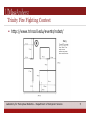
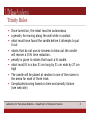
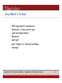
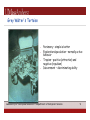
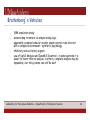
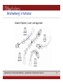
Embedded Systems Lecture #1 Overview of the Course The Trinity Project History Cabling for Electronics Projects TuteBot Laboratory for Perceptual Robotics – Department of Computer Science Course Web Site www-robotics.cs.umass.edu/~grupen/503 If you need it: Edlab accounts http://www-edlab.cs.umass.edu/ • Linux workstations are : • machines: elnux0 - elnux34 Laboratory for Perceptual Robotics – Department of Computer Science 2 Notes: Course Setup: all work should be done in the course subdirectory (cd cs503) all common files should go in the common directory (/courses/ cs500/cs503/cs503) usernames - first character of their first name appended by lastname (truncated at 8 characters) • Example: rgrupen - for Rod Grupen initial passwords 8 digit Student ID numbers unless you already had an account last semester [email protected] will go to each person in that class, plus the professor and TA. .forward file - add your preferred email address The print quota is 300 pages initially + 200 pages per class. Laboratory for Perceptual Robotics – Department of Computer Science 3 Embedded Systems … a system in which one or more processors act through a physical system to interact with the external environment! Lecture Units: • mechanism • kinematics • dynamics • signal detection • electronics • RT computing • AI electromechanical mechanism computation I/O circuitry Laboratory for Perceptual Robotics – Department of Computer Science Trinity Fire Fighting Contest http://www.trincoll.edu/events/robot/ Laboratory for Perceptual Robotics – Department of Computer Science 5 Trinity Rules Once turned on, the robot must be autonomous a penalty for moving along the wall while in contact robot must have found the candle before it attempts to put it out robots that do not use air streams to blow out the candle will receive a 15% time reduction. penalty is given to robots that touch a lit candle. robot must fit in a box 31 cm long by 31 cm wide by 27 cm high The candle will be placed at random in one of the rooms in the arena for each of three trials Complicated scoring based on time and penalty factors (see web site) Laboratory for Perceptual Robotics – Department of Computer Science 6 2005 Trinity Trials Team #2 - Eugene Kolnick, Will Wagner, Nolan Schelper, Todd Robbins, Thierry Elie Laboratory for Perceptual Robotics – Department of Computer Science Grey Walter’s Tortoise 1953 experiment in cybernetics One motor, 2 valve control logic Light and bump sensors Behaviors: seek light seek “subject-to” obstacle avoidance recharge Laboratory for Perceptual Robotics – Department of Computer Science 8 Grey Walter’s Tortoise Parsimony – simple is better Exploration/speculation – normally active behavior Tropism – positive (attraction) and negative (repulsion) Discernment – discriminating ability Laboratory for Perceptual Robotics – Department of Computer Science 9 Braitenberg’s Vehicles 1984 simulation study sensors map to motors via simple analog logic apparently complex behavior results simple control rules interact with a complex environment – synthetic psychology inhibitory and excitatory signals Law of Uphill Analysis and Downhill Invention - in some systems it is easier to invent than to analyze, in others, complete analysis may be impossible, but the systems can still be built Laboratory for Perceptual Robotics – Department of Computer Science 10 Braitenberg’s Vehicles Coward, Explorer, Lover, and Aggressor Laboratory for Perceptual Robotics – Department of Computer Science 11 Project #1 - photovore see web site for details! Dirk Ruiken-2005! Chris Vigorito-2005! Laboratory for Perceptual Robotics – Department of Computer Science 12 Project #1 - project management A draft project plan is the first step of every project---before the first circuit is prototyped.! ! The plan enumerates all the tasks required and sets completion times. This level of description makes it clear that all aspects of the project have been considered (nothing has been left out), how tasks depend on one another, and provides reasonable time estimates to help you think. ! ! It also should include a description of the products (designs, numerical values) that verify the completion of each task or establish parameters necessary for subsequent tasks.! ! Inevitably, the plan will need to be modified as it unfolds so it make sense to do it in a way that is easily edit-able. I like the excel spreadsheet for a Gantt chart---I have template you can use, but there are other tools.! ! .! Laboratory for Perceptual Robotics – Department of Computer Science 13 Project #1 - project management Task!1. Design! a) b) c) d) e) f) CdS/R2/Rmotorresistances! voltage divider, Vout (light/dark)! switch logic! circuit layout (pin-2-pin)! chassis structure, motor mount, wheels/skid concept! design checkout! Task!2. Prototype! a) b) circuit breadboard! logic/performance checkout! a) b) summary of design, implementation! critical evaluation! Task!3. Implementatio! Task!4. Demonstration! Task!5. Report! Laboratory for Perceptual Robotics – Department of Computer Science 14 project management GANTT chart 9/12! Task ! Task ! Task ! Task ! Task 9/19! 9/26! 9/30! 1 - Design! 2 - Prototype! 3 - Implement! 4 - Demo! 5 - Report! include all the subtasks (1a, 1b, …)! evaluate your schedule - adjust weekly! Laboratory for Perceptual Robotics – Department of Computer Science 15 project reporting – individual weekly lab report NO MORE than 2 pages in ONE PDF FILE (LastNameReport#n.pdf)! ! Include completed products of the previous week's tasks (drawings, designs, numerical values), note any variations in your plan, and include a revised project plan. ! ! Reports don’t need to be beautifully written, but must be organized to be read.! ! It's tempting to jump right to a picture of your final concept in week 1, but stick to your plan and work out the results of preliminary subtasks first. The project plan minimizes the chances that you'll waste time and make costly mistakes.! ! I will review and grade notebooks every week. Grades will reflect the completeness of the design process, critical analyses, experimental evaluation, and weekly project management.! Laboratory for Perceptual Robotics – Department of Computer Science 16 project reporting – final reports NO MORE THAN 5 pages! ! includes the last (final) revision of the project plan, summarizes all the products at a level of detail adequate to reproduce your results! ! draw conclusions about the final performance and revisions you would make it you had to do it over again! ! It should be written using complete sentences and a logically organized sequence of thoughts.! ! In weeks when you submit final project reports, individual weekly lab reports are not required.! Laboratory for Perceptual Robotics – Department of Computer Science 17 Implementation suggestions Soldering! Male/female headers! Wheels! Motors (mounting, galvanized wire, sheet Al)! DIP sockets - potentiometers, DPDT switches! SIP sockets - CdS photoresitors! Creativity is encouraged, but only if it’s on your GANTT chart! Know what risks you’re taking and plan for them.! Laboratory for Perceptual Robotics – Department of Computer Science 18 Soldering solder - a layer of lead-tin alloy with a relatively low melting point around a core of flux that cleans the junction with which to fix two conductors together in an intimate (low resistance) junction.! ! No - stainless steel, aluminum - they have an oxide coating! Yes - solid copper, “tinned” copper, brass, iron, most steels! ! heat up both surfaces to be joined to the melting point of the solder, feed a small amount of fresh solder from the reel into the joint! ! heat the joint with a soldering iron---set the temperature on your soldering station to 320 degrees Celcius---molten solder is hot enough to burn you.! ! solder wets the metal being joined---check the shape of the solder meniscus. If the solder forms a small spherical blob on the metal, the joint is a bad "dry" joint. If the surface of the solder is “sucked in” to the joint (concave), then you probably have a good joint.! Laboratory for Perceptual Robotics – Department of Computer Science 19 Tips on Soldering Metal surfaces must be clean. Remove dull (oxide) surfaces from copper (make the surface bright). Components (transistors, resistors) have thermal stress limits---beware overheating---if in doubt, use the little heat-sinks (aluminum clamps) on the leads of a component to protect it by adding thermal mass during soldering. Typically only a few seconds of heat need to be applied to small joints.! ! ! Solid wire - easy to work with, but solid wires that flex will eventually fail by metal fatigue, giving rise to malfunctions that are hard/impossible to locate.! ! Thin gauge stranded wire - survives flexion much better. Twist and “tin” the end of the wire. Two such wires soldered together form a rigid joint. If possible, “strain relieve” the joint so that flexure is confined to the part of the wire that is still stranded. A short length of heat shrink tubing over the end of the wire is usually enough to reinforce (and protect/insulate) the rigid joint.! ! Laboratory for Perceptual Robotics – Department of Computer Science 20 Debugging Check your work as you go!!! Bad joints mean intermittent circuit problems that are hard to find. Connect what you intended to connect and nothing else. Configure your multimeter to the continuity/diode check mode and check every joint as you make it. When you’re done, do a basic check before you apply power to a circuit or all your hard work may go poof. Watch out for excessive current consumption by the circuit--usually indicative of a short.! ! Desoldering - A bad solder joint can be repaired by heating it up and using a solder suction device. Take care to avoid thermal stress limits when desoldering.! ! It's difficult to desolder multiple pin IC packages. Always put integrated circuits in sockets when making an experimental board. Sockets isolate ICs from thermal stresses and also make it easier to debug a board because you can check voltages before you install the chip or you can replace it if necessary.! Laboratory for Perceptual Robotics – Department of Computer Science 21 Sockets and Connectors Connectors are the bane of electronics---they are generally more costly to make and cause errors at a higher rate than other components of a circuit. Connectors should be unambiguous so that power and signal can not be misapplied. ! ! Our general purpose (perforated) boards are drilled with holes on 0.1" centers. Typically, we use male and female headers to connect to boards. Put female headers on the board, use male headers as plugs that fit into them. The Handyboard user’s manual illustrates a very nice way of cabling using ribbon cables soldered to male headers, insulated and strain relieved using shrink tube, and polarized to fit into the female header.! sensor signal! +5V supply! ground! Laboratory for Perceptual Robotics – Department of Computer Science 22