1
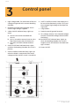
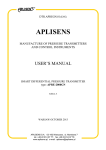
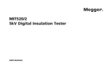
GE Energy
Programma®
VIDAR
Vacuum tester
User's manual
VIDAR
Contents
1 General .........................................................4
Flashover threshold voltage ....................................4
2 Safety ............................................................5
Safety instructions ..........................................5
3 Control panel ...............................................6
Panel overview ..............................................................6
4 Operating instructions ..............................7
4.1 Connecting ...............................................................7
4.2 Conducting a test .................................................7
Disconnection after testing ......................................8
5 Troubleshooting ..........................................9
6 Specifications ........................................... 10
NOTICE OF COPYRIGHT & PROPRIETARY RIGHTS
© 2005, Programma Electric AB. All rights reserved.
The contents of this manual are the property of Programma Electric AB. No part of this work may be reproduced or transmitted in any form or by
any means, except as permitted in written license agreement with Programma Electric AB. Programma Electric AB has made every reasonable
attempt to ensure the completeness and accuracy of this document. However, the information contained in this manual is subject to change
without notice, and does not represent a commitment on the part of Programma Electric AB. Any attached hardware schematics and technical
descriptions, or software listings that disclose source code, are for informational purposes only. Reproduction in whole or in part to create
working hardware or software for other than Programma Electric AB products is strictly prohibited, except as permitted by written license
agreement with Programma Electric AB.
TRADEMARK NOTICES
Programma® is a registered trademark of Programma Electric AB. All other brand and product names mentioned in this document are
trademarks or registered trademarks of their respective companies.
Programma Electric AB, Eldarvägen 4, SE-187 75 TÄBY, Sweden.
Tel +46 8 510 195 00. Fax +46 8 510 195 95.
E-mail [email protected] Internet www.ge.com/energy
Programma Electric AB
ZP-BR01E R100
3
VIDAR
1
General
The VIDAR vacuum tester is used to test the ability of the breaking chamber in a vacuum circuit
breaker to inhibit flashover. The rugged, lightweight, compact and portable VIDAR is ideal for
field work.
The vacuum bottles in vacuum breakers do not
last forever. Leakage starts after years or decades
and the bottles fill with air making the breaker
unreliable. In most cases the leakage process is
rapid once it has started. In addition to leakage,
dirt on the poles and on the exterior surface of the
bottle can make it unsafe during operation. The
mechanics of the breaker can become misaligned
so that the distance between the poles no longer
is adequate. Vidar, introduced in 1985, uses high
voltage DC to test the integrity of vacuum breakers. There are some 2000 units of Vidar in field
service all over the world that perform daily tests
on the integrity of vacuum breakers.
Flashover threshold
voltage
The curve shown in Fig. 1 illustrates the relationship between a vacuum chamber’s internal
pressure and its ability to inhibit flashover. This
relationship permits the vacuum to be checked
indirectly by measuring the voltage threshold.
One special advantage of this method is that you
do not need to disassemble the circuit breaker in
order to test it.
The voltage shall be selected so that test point A
(see diagram) is sufficiently far from point B (when
the chamber is filled with air). However the electric
stress in the chamber must not be too high. In normal situations the pressure is less than 10-2 mbar.
For guidance on test voltage refer to IEC 694 and
ANSI C37-06 standards.
log Ud
A
Up
B
pp~10-2mbar
Fig. I. Flashover threshold voltage plotted against pressure in
vacuum chamber.
4
po log p
p : chamber pressure
po: atmos. pressure
pp: max. pressure on passing voltage test
ud : breakdown voltage
up : test voltage
Programma Electric AB
ZP-BR01E R100
VIDAR
2
Safety
Safety instructions
Important
Important
Always turn the equipment off before connecting.
Always use safety connecting leads.
Read the manual and comply with the following
instructions before using the VIDAR.
Always connect protective earth (ground).
Always comply with local safety regulations.
Never leave the instrument unattended while it is
turned on.
Warning
People with pacemakers must not use the VIDAR
since a pacemaker can be disturbed by the electrical discharges.
When testing a circuit breaker that is permanently mounted you must make certain that there is
no risk of burning out the collector busbar if it
can not be disconnected.
Circuit breakers on vehicles and also circuit
breakers of the plug-in type must be tested outside their holders.
Applying abnormally high voltage across a pair of
contacts in vacuum may be dangerous. However,
as a precautionary measure against possibility of
application of higher than recommended voltage
(or a contact spacing below normal), it is recommended that all operating personnel stands at
least 3 m (10 ft) away in front of the breaker.
Use only approved mains detachable cable set
with the instrument. Main supply cables shall be
rated for the maximum current for the equipment
and the cable shall meet the requirements of IEC
60227 or IEC 60245. Mains supply cables certified
or approved by a recognized testing authority are
regarded as meeting this requirement.
Unplug the instrument from the mains supply
when it is left unattended or not in use.
Refer all servicing to Programma authorized
personnel.
If you need to return the instrument, please use
either the original crate or one of equivalent
strength
High voltage/current on input/output terminals.
Do not attempt to service the instrument yourself. Opening or removing covers may expose you
to dangerous voltage. If you attempt to service
the instrument yourself the warranty is no longer
valid.
Do not use any accessories that are not intended
for use together with the instrument.
Disconnect the instrument from the mains before
cleaning. Use a damp cloth for cleaning. Do not
use liquid cleaners or aerosol cleaners.
Programma Electric AB
ZP-BR01E R100
5
VIDAR
3
Control panel
1. High voltage cable. For connection of the test
voltage and ground to the vacuum breaking
chamber.
2. Red HIGH-VOLTAGE warning lamp. Shows
that the high voltage is applied.
3. Yellow CANCEL indicator lamp. Lights up
when:
a) the test interval has exceeded one
minute.
b) you try to conduct a one minute test less
than two minutes after the latest test.
c) the HIGH-VOLTAGE indicator malfunctions.
4. Green ACCEPTABLE Indicator lamp. Lights
up when the breaking chamber test result is
positive.
6. SAFETY CONTROL KNOBS. Both knobs must
be turned simultaneously to their TEST positions to apply high voltage to the object being tested.
7. Long handles.
8. Protective earth (ground) terminal.
9. Test voltage selector. Five standard voltages
and one customized voltage, determined at
the factory.
10. Red DEFECTIVE indicator lamp. Lights up
when the breaking chamber test result is
negative, when the flashover threshold voltage is too low.
11. Power ON/OFF.
5. Green POWER ON indicator lamp. Lights up
when the VIDAR is connected to the mains
voltage and the ON/OFF switch is turned ON.
6
Programma Electric AB
ZP-BR01E R100
VIDAR
4
Operating
instructions
4.1 Connecting
Important!
Read the manual and comply with the
Safety instructions, see page 5, before using VIDAR.
Always comply with local safety regulations.
1. Check that the circuit breaker is in OPEN position.
2. Check that the master ON/OFF switch on
the VIDAR is in OFF position and that the red
HIGH-VOLTAGE warning lamp is not flashing.
3. Ground VIDAR (8).
4. Connect the part with the black crocodile
clamp of the high-voltage cable (1) to the control mechanism side of the breaking chamber.
5. Connect the part with the red crocodile clamp
of the high-voltage cable (1) to the other terminal on the breaking chamber.
6. Connect VIDAR to the mains power.
4.2 Conducting a test
1. Connect the VIDAR as instructed in section
4.1 Connecting.
2. Select the desired test voltage depending on
the type of breaking chamber being tested.
Note For guidance on test voltage refer to
IEC 694 and ANSI C37-06 standards.
3. Turn the power ON/OFF switch to the ON position. The green lamp beside the switch will
light up.
4. Using both hands, turn the two SAFETY CONTROL KNOBS to their respective end limits
and keep them in that position.
The red HIGH-VOLTAGE warning lamp will
flash.
a. If the green ACCEPTABLE lamp lights up
and remains lighted for at least five seconds the test is complete and the breaking chamber can be considered in good
condition. Release the SAFETY CONTROL
KNOBS.
b. If the red DEFECTIVE lamp lights up and
remains lighted for at least five seconds,
release the SAFETY CONTROL knobs
Turn off the power and check the ground
connection and other connections.
Start again from point 3.
If the red DEFECTIVE lamp lights up again,
the breaking chamber must be considered
defective.
Note Any metallic discharge sounds that are
heard during the test are of no importance.
The results shall be based solely on the
lighting up of either the green ACCEPTABLE
lamp or the red DEFECTIVE lamp.
5. When the test is completed turn the power
ON/OFF switch on the VIDAR to its OFF position.
Programma Electric AB
ZP-BR01E R100
7
VIDAR
Note The yellow indicator lamp lights if the test
lasts longer than 1 minute.
If you want to conduct a full time 1 minute
test after that, there must be a 2 minutes
pause before starting next test. (This
pause permits proper resetting of VIDAR’s
internal timercounter.)
Disconnection after testing
1. Check that the power ON/OFF switch is at
the OFF position.
2. Remove the ground connection (black cable
terminal) and connect it to the metallic part
of the highvoltage cable (red cable terminal)
before removing it from the circuit breaker.
3. Remove the copper line from the circuit
breaker.
Note Electrostatic charges can build up on:
a) adjacent insulated parts
b) the metallic centre-section of the breaking chamber
c) the entre centre part of dual breaking
chambers due to the fact that the VIDAR
uses DC.
When a ground connection is established,
it takes (depending on surface conditions)
about 10 seconds for statically charged
parts to assume ground potential. As a
rule these electrostatic charges do not
entail any serious risk.
8
Programma Electric AB
ZP-BR01E R100
VIDAR
5
Troubleshooting
Fault
Cause
Remedy
Green POWER ON
lamp does not
light.
Probably no mains power.
Check the mains, the master ON/OFF switch
and the automatic fuse adjacent to the mains
nameplate.
Red HIGH-VOLTAGE warning
lamp does not
flash.
Yellow CANCEL
lamp lights up
instead.
The lamp in the HIGH-VOLTAGE
warning lamp is probably faulty.
Unscrew and remove the red protector lens
(turn it anticlockwise). Push the lamp down,
then twist slightly anticlockwise to release it
from its bayonet socket. Pull the lamp out of its
socket and replace it with a new one (Halogen
12 V, 5 W BA9 type, Programma Electric art. no.
is 34-00020).
Insert the light bulb in the socket, push the lamp
down, then twist slightly clockwise. Replace the
red protective lens by turning it clockwise.
Yellow CANCEL
lamp Ilghts up
but glows weakly.
Wrong mains voltage.
Check to see that the mains voltage is the same
as that shown on the mains nameplate.
Programma Electric AB
ZP-BR01E R100
9
VIDAR
6
Specifications
Specifications VIDAR
Specifications are valid at nominal input voltage and an ambient
temperature of +25°C, (77°F). Specifications are subject to change
without notice.
Environment
Application field
Personal safety
Temperature
Operating
Storage & transport
Humidity
The instrument is intended for use in
high-voltage substations and industrial environments.
Maximum permissible transient
current through the external load is
12 mA. Maximum discharge time for
internal high-voltage circuit is 0.3 s.
0°C to +50°C (32°F to +122°F)
-40°C to +70°C (-40°F to +158°F)
5% – 95% RH, non-condensing
CE-marking
LVD
EMC
Low Voltage Directive 73/23/ EEC am.
by 93/68/EEC
EMC Directive 89/336/EEC am. by
91/263/EEC, 92/31/EEC and 93/68/
EEC
General
Mains voltage
Power consumption
(max)
Protection
Dimensions
Instrument
Transport case
Weight
115 / 230 V AC (switchable), 50 / 60 Hz
69 VA
Overload cut-out
250 x 210 x 125 mm
(9.8” x 8.3” x 4.9”)
460 x 430 x 210 mm
(18.0” x 17” x 8.3”)
6.9 kg (15.5 lbs)
10.7 kg (23.6 lbs) with accessories and
transport case
Measurement section
Indicators
Green lamp
Red lamp
Yellow lamp
Indicates an approved breaking
chamber, lights up when the current
is below 0.3 mA
Indicates a defect breaking chamber, lights up if the current exceeds
0.3 mA
Indicate that the test was interrupted
Output
Standard voltages,
switchable
Customized voltage
Ripple
10
10, 14, 25, 40 and 60 kV DC
Between 10 and 60 kV DC. Determined at the factory. Default voltage
is 50 kV
Max 3%
Programma Electric AB
ZP-BR01E R100