1
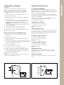
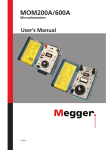
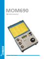
MOM690 Microhmmeter A Megger Group Company M O M 690 MOM690 Microhmmeter Measuring resistance is an important part of maintaining high-voltage breakers and disconnecting switches. Instruments that measure the resistance of high-current contacts and other transmission elements have been included in the Programma line of products for many years. MOM690™ supplements our family of microhmmeters. In addition to high current capacity, MOM690™ features microprocessor-based measurement, storage and reporting. The built-in software enables you to carry out an individual test or an entire series of tests and store the results. With the optional MOMWin™ software you can also export the test results to a PC for further analysis and reporting. Ranges are set automatically, resistances are measured continually and test results can be automatically captured at a preset test current. What could be simpler? After testing a breaker with a CT mounted in its current circuit, e.g. dead tank and GIS breakers, some standards recommended that the CT is demagnetized. This troublesome task can be accomplished quickly and easily thanks to the MOM690's AC output. The AC output can also be used as a general multi-purpose current source in different applications. 2 Optional accessories IMPORTANT! PC Software MOMWin Read the User’s manual before using the instrument. Measuring the resistance of a breaker 1. Make certain the line is de-energized on both sides of the breaker. 2. Ground the breaker on one side and make certain it is closed. 3. Ground the microhmmeter. 4. Make certain the microhmmeter's ON/OFF switch is OFF while making connections. 5. Connect the current cables to the DC+ and COM terminals and the sensing cables to the sensing inputs to both sides of the breaker, making sure that the polarities match properly. IMPORTANT: The sensing cables must be connected inside the current cables. Otherwise the test data will be incorrect. See Fig. An optional Windows® program named MOMWin is available for MOM690. It can be used to control measurement, analyse the results and report the results from a PC. It also enables you to retrieve test results stored previously in MOM690. All readings are saved in ASCII-format and can be easily exported to your favourite spreadsheet program. Results can be presented in table or diagram form in MOMWin. The program runs in Windows® 95, 98, NT, 2000 or XP. Minimum requirement is a 486 computer with 8 MB of RAM. Incl. serial cable for RS-232 port. Cable set 15 m (49 ft) 2 x 15 m (49 ft), 95 mm2 (current cables). 6. Switch on the MOM690. 2 x 15 m (49 ft), 2.5 mm2 (sensing cables). 7. Select "AUTO" or "MAN" with the <FUNC>-button. Weight: 29.4 kg (64.8 lbs) 8. Set output current to zero to start the measurement. 9. Increase the current to the desired value (600 A for example). Cable extension sets Measuring resistance at busbar joints Since all current cables have bayonet connectors, standard cables can be easily prolonged with 5- or 10-metre extension sets if so desired. In situations requiring high currents and long cable lengths, heavier cable sets may be necessary however. 1. Make certain the line is de-energized and the test object is grounded. Extension cable set No. 1 2. Ground the microhmmeter. 2 x 5 m (16 ft), 50 mm2 (current cables). 3. Make certain the microhmmeter's ON/OFF switch is OFF while making connections. 2 x 10 m (33 ft), 2.5 mm2 (sensing cables). 4. Connect the microhmmeter's current cables to the test object. Do not connect the sensing cables. Measurement will be done manually using an external portable voltmeter. Extension cable set No. 2 10. Read the resistance value. 5. Switch on the MOM690. 6. Select "MAN" with the <FUNC>-button. 7. Set output current to zero to start the measurement. 8. Increase the current to the desired value (100 A for example). 9. Using an external voltmeter, measure the voltage drop across each contact element within every section of the busbar being tested. The voltmeter must be set to DC. 10. Calculate the actual resistance. Example: If the voltage drop is 0.0067 V at a current of 100 A, the resistance will be 0.0067/100 Ω, i.e. 67 µΩ. Measuring the resistance of a breaker Weight: 7.5 kg (16.5 lbs) 2 x 10 m (33 ft), 50 mm2 (current cables). 2 x 15 m (49 ft), 2.5 mm2 (sensing cables). Weight: 15 kg (33 lbs) Calibration shunt An optional calibration shunt (600 A/60 mV) can be ordered for MOM690, that enables you to make certain that the instrument readings remain correct. Transport case XL With space for the standard 5 m cable set + extension cable set No. 1 or No. 2. Measuring resistance at busbar joints 3 M O M 690 Application example M O M 690 Specifications MOM690 Max. load resistance / current, 230 V model Specifications are valid at nominal input voltage and an ambient temperature of +25°C, (77°F). Specifications are subject to change without notice. Environment Application field Temperature Operating Storage & transport Humidity The instrument is intended for use in high-voltage substations and industrial environments. 0°C to +50°C (32°F to +122°F) -40°C to +70°C (-40°F to +158°F) 5% – 95% RH, non-condensing Low Voltage Directive 73/23/ EEC am. by 93/68/EEC EMC Directive 89/336/EEC am. by 91/263/EEC, 92/31/EEC and 93/68/EEC EMC General Mains voltage Power consumption (max) Protection 115 / 230 V AC, 50 / 60 Hz 115 V, 5980 VA (at 600 A output) 230 V, 9660 VA Miniature circuit breaker, thermal fuse, software Measurement section Ammeter At 300 A Max. current 10 mΩ 575 A Voltage (V) 0 50 100 200 300 400 500 5751) 600 700 8002) 7.3 6.9 6.4 5.5 4.8 3.9 3.0 2.5 2.2 1.5 0.9 Max. load time Input current (A) – 0.8 30 min. 10 min. 10 90 s 19 50 s 30 s 38 15 s 10 s 8s 52 5s – Output AC (CAT I), 115 V model Current (A) 0 660 Voltage (V) 8.7 3.5 Max. load time Rest time Cont. – 2s 4 min. Note: The DC and AC outputs must not be loaded at the same time. Output DC (CAT I), 230 V model Current (A) 0 50 100 200 300 400 500 600 700 7501) 8002) Current (A) 0 660 Voltage (V ) Max. load time Input current (A) 9.4 – 0.4 9.0 30 min. 8.6 10 min. 6 8.0 90 s 7.2 50 s 6.4 40 s 5.7 30 s 5.0 15 s 33 4.3 8s 3.8 5s 3.6 – 42 Voltage (V AC) 11.2 4.5 Max. load time Rest time Cont. 2s Note: The DC and AC outputs must not be loaded at the same time. Standard 2 x 15 m 95 mm² + Ext. 1 3 mΩ 360 A Current (A) Output AC (CAT I), 230 V model 0 – 200 mΩ, > 200 mΩ not specified 1 μΩ 100 – 800 A, ±1% of reading + 1 digit 50 – 99 A, ±(2% of reading + 2 digits) 0 – 49 A, not specified Standard + Ext. 1 6 mΩ 420 A 480 A 18 mΩ 1.8 mΩ 690 A Note: The above figures shows maximum load time from cold state 25°C. They are not valid for repeated tests Max. load resistance / current, 115 V model Standard 570 A 2 x 15 m 95 mm² 1) Maximum current with standard cables 2 x 5 m 50 mm² 2) At 800 A and above, instant shut off 0 – 800 A 1A 100 – 800 A, ±1% of reading + 1 digit 50 – 99 A, ±(2% of reading + 2 digits) 0 – 49 A, not specified Resistance Cable set 18 mΩ 3.0 mΩ 750 A Stadard + Ext. 1 11 mΩ Note: The above figures shows maximum load time from cold state 25°C. They are not valid for repeated tests 350 x 270 x 220 mm (13.8” x 10.6” x 8.7”) Transport case 610 x 290 x 360 mm (24.0” x 11.4” x 14.2”) Weight, 115 V 24 kg (52.9 lbs) model 38.9 kg (85.7 lbs) with accessories and transport case Weight, 230 V 23.7 kg (52.2 lbs) model 38.6 kg (85.1 lbs) with accessories and transport case Available languages English, French, German, Spanish, Swedish Current cables 2 x 5 m (16 ft), 50 mm² Sensing cables 2 x 5 m (16 ft), 2.5 mm² Optional current cable sets Ext.1 Extension 2 x 5 m, 50 mm² Ext.2 Extension 2 x 10 m, 50 mm² 2 x 15 m (49.2 ft) 95 mm² Range Resolution Inaccuracy At 300 A At 600 A Max. current Stadard + Ext. 1 14 mΩ 1) Maximum current with standard cables 2 x 5 m 50 mm² 2) At 800 A and above, instant shut off Dimensions Instrument Range Resolution Inaccuracy Standard Output DC (CAT I), 115 V model CE-marking LVD Cable set 10 mΩ 540 A 4 – 4 min. Grounding terminal ❷ Connection for mains voltage ❸ Miniature circuit breaker for mains ❹ Switch for mains voltage ❺ ❻ ⓮ ❶ Variable transformer AC current output ❷ ❿ ❽ ⓫ ❼ Common output terminal ❽ DC current output ❾ Voltage measurement input ❿ Display ⓫ Setting selector ⓬ Function selector ⓭ Interrupts current and toggles the display between resistance and voltage ⓮ RS 232 Serial interface M O M 690 ❶ ⓬ ❸ ⓭ ❹ ❾ ❼ ❻ ❺ Information about current generation or memory location. Value of the generated current. Indicates whether the current is above (<) or below (>) a preselected value. Selected test current for ”Auto”/”DC Off”. Scroll using the <>- button. Selected function. Scroll using the <FUNC>-button. Shows the measured resistance or voltage value. Toggle by pressing the <Ω>-button. Ordering information Art.No. Complete with: Cable set standard GA-05055 Ground cable GA-00200 Transport case GD-00182 115 V Mains voltage 230 V Mains voltage BB-41190 BB-42390 MOM690 Optional accessories Cable set and current shunt PC Software MOMWin Incl. serial cable for RS-232 port Cable set 15 m (49 ft) Extension cable set No. 1 Extension cable set No. 2 Calibration shunt Transport case XL 5 BB-8010X GA-09155 GA-05057 GA-05107 BB-90024 GD-00042 NOTICE OF COPYRIGHT & PROPRIETARY RIGHTS © 2008, Programma Electric AB. All rights reserved. The contents of this document are the property of Programma Electric AB. No part of this work may be reproduced or transmitted in any form or by any means, except as permitted in written license agreement with Programma Electric AB. Programma Electric AB has made every reasonable attempt to ensure the completeness and accuracy of this document. However, the information contained in this document is subject to change without notice, and does not represent a commitment on the part of Programma Electric AB. TRADEMARK NOTICES Megger® and Programma® are trademarks registered in the U.S. and other countries. All other brand and product names mentioned in this document are trademarks or registered trademarks of their respective companies. Programma Electric AB is certified according to ISO 9001 and 14001. Programma Electric AB Eldarvägen 4 Box 2970 SE-187 29 TÄBY Sweden T +46 8 510 195 00 F +46 8 510 195 95 [email protected] www.programma.se Subject to change without notice. Art. No. ZI-BB04E Doc. BB0214CE 2008