1
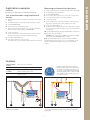
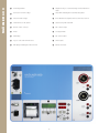
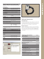
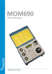
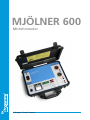
MJÖLNER 600
Microhmmeter
A Megger Group Company
MJÖ LN E R 600
MJÖLNER 600
Microhmmeter
The MJÖLNER™600 is designed to measure the resistance of circuit breaker contacts, bus-bar joints, contact
elements in bus-bars and other high-current links. The product has been designed with safety, ease of use and
versatility in mind.
The microhmmeter ��������������
conducts true ���
DC ripple
�������������������������������������������������������������������������
free current and��������������������������������������������������
can be used anywhere to measure a low resistance
value with high accuracy. With MJÖLNER 600 it is possible to make measurements according to the DualGround™
method. This means that the test object will be grounded on both sides throughout the test giving a safer, faster and
easier workflow.
Choose the MJÖLNER 600 with excessive power resources for demanding applications, superior measurement
accuracy and when 300 Amp continuous is required.
The lightweight and rugged suitcase design makes MJÖLNER 600 an excellent choice when you need a portable
solution in the field. When the case is closed, the product can withstand the impact of water, dust or sand – it even
floats.
Two optional accessories are; a remote control and the PC software MJÖLNER Win that is compatible with IPS–CBEX
and have export functions for tables to Microsoft® Excel®.
2
Measuring resistance at bus-bar joints
IMPORTANT
Read the User’s manual before using the instrument.
2. Ground the bus-bar on both sides.
Test a circuit breaker using DualGround
testing
1. Make certain the line is de-energized on both sides of the circuit
breaker.
2. Ground the breaker on both side and make certain it is closed.
3. Ground MJÖLNER 600.
4. Connect the current and sensing cables.
1. Make certain the line is de-energized on both sides of the bus-bar.
3. Ground MJÖLNER 600.
4. Connect the current cables Do not connect the sensing cables.
5. Select "Continuous Mode" in the "Setup Menu".
6. Set the test current.
7. In the "Setup Menu", set the current clamp to "On" and key in
the proper sensitivity of the current clamp you are using.
8.
Press the <START/STOP> key.
5. Apply an external current clamp to one of the grounding cables
and connect the clamp outputs to MJÖLNER 600.
9. Using an external voltmeter, measure the voltage drop (voltage)
across each contact element within every section of the bus-bar
being tested.
6. Set the test current.
10. Stop the measurement by pressing <START/STOP> or <ESC> keys.
7. In the "Setup Menu", set the current clamp to "On" and key in
the proper sensitivity of the current clamp you are using.
11. Calculate the actual resistance.
Example: If the voltage drop is 0.0067 V at a current of 100 A,
the resistance will be 0.0067/100 Ω, i.e. 67 µΩ.
8. Press the <START/STOP> key.
9. The result is shown after some seconds.
The result is saved, you can make a printout and/or run a new test
Note: The method above can be automized using a TM1800 for
measuring and storing the results. It is of course applicable for all
resistance measuring on multiple contacts e.g. circuit breaker
contacts.
Features
Fully automatic
testing
Micro processor controlled
Database
CEBEX/IPS integration
Rugged and
portable
Lightweight suitcase design withstands the
impact of water, dust or sand
Safe test
DualGround
Remote control
You can make tests with both sides of the test object grounded, an
additional safety feature.
Equipment and methods that supports
DualGround™ testing are associated with
the DualGround symbol. This symbol certifies the use of groundbreaking technology
and methods that enables a safe, fast and
easy workflow with both sides grounded
throughout the test.
Using an external voltmeter, measure the voltage drop (voltage)
across each contact element within every section of the bus-bar
being tested.
3
MJÖ LN E R 600
Application examples
MJÖ LN E R 600
❶
Grounding terminal
❿
Adjustment keys to set the measuring current and all menu
values
➋
Connection for mains voltage
⓫
Status LED’s indicating the actual measuring status
➌
Switch for mains voltage
⓬
Error LED when the adjusted current could not be reached
➍
Serial interface for PC (RS232
⓭
Start/Stop key with status LED
➎
Remote control connector
⓮
DC+ current output
➏
Printer
⓯
Sensing terminals
➐
LCD Display
⓰
DC- current output
➑
Keys to control the menu functions
⓱
Shunt output
➒
LED displays indicating the value of R and I
⓲
Clamp sense input
❶
⓮
❷
❸
⓯
⓰
❼
❹
❾
❺
❿
⓫
❽
⓬
❻
4
⓭
⓱
⓲
MJÖ LN E R 600
Specifications MJÖLNER 600
Specifications are valid at nominal input voltage and an ambient
temperature of +25°C, (77°F). Specifications are subject to change
without notice.
Environment
Application field
Temperature
Operation
Storage
Relative humidity %RH
For use in high-voltage substations
and industrial environments.
-20 to +50°C (-4°F to +122°F)
-40ºC to +70ºC (-40°F to +158°F)
5%-95%, non condensing
CE-marking
LVD
EMC
EN 61010-1:2001
EN 61326:1997 + A1:1998 + A2:2001
+ A3:2003
General
Mains voltage
Power consumption
Protection
Dimensions
Weight
100 - 120, 200 - 240 V AC, 50 / 60 Hz
(max) 39 A at 100 V, 18 A at 230 V
Thermal fuses, Software
486 x 392 x 192 mm
(19” x 15.4” x 7.6”)
13.8 kg (30.4 lbs)
Measurement section
Measuring range
Resolution
0 – 999.9 mΩ
0.1 μΩ below 1.0 mΩ
1 μΩ
below 10 mΩ
10 μΩ
below 100 mΩ
100 μΩ below 1000 mΩ
Inaccuracy, 50 – 600 A, Typ ±0.3 μΩ, Max. ±2 μΩ
ta 10 - 40ºC, R < 1 mΩ
Outputs
DC+ / COM
Range
Output voltage (max)
5 – 600 A DC (steps of 1 A)
5.25 V DC at 600 A
Remote control
Optional accessories
MJÖLNER Win
The Windows program makes it easy to manage / save all test results
in a simple way. All information, meta-data of the test object e.g. a
circuit breaker and the test results are stored together and they can
easily be transferred to Microsoft® Excel for further analysis.
Remote control
Many times, you place the test equipment on the ground while the
cables are connected high up on a circuit breaker. In these situations,
it can save a lot of time using a remote control during the test. The
remote control has most of the functionality in the MJÖLNER 600
such as starting and stopping, setting the test current and read out
the test values.
OUTPUT 100 μV/A
Shunt output
Inaccuracy
Inputs
SENSE
INPUT DC current
clamp
Input sensitivity
Input impedance
From internal shunt 60 mV at 600 A
±1%
Max. 20 V between terminals and to
protective earth (ground).
Max. 20 V between terminals and to
protective earth (ground).
Ordering information
Art.No.
MJÖLNER 600
Incl. Std. cable set 3 m, (current cables 2 x 3 m,
35 mm2 and sensing cables 2 x 3 m), Ground cable
Incl. Std. cable set 5 m, (current cables 2 x 5 m,
35 mm2 and sensing cables 2 x 5 m), Ground cable
Incl. Std. cable set 3 m, (current cables 2 x 3 m,
35 mm2 and sensing cables 2 x 3 m), Ground cable
and DC Current clamp (200 A / 20 mV)
Adjustable 0.1 – 20 mV/A
>1 MΩ
BB-59090
BB-59091
BB-59092
Optional accessories
MJÖLNER Win
MJÖLNER Win
Windows® software
BD-8010X
Remote control
Temperature probe
BD-90010
BD-90012
Thermal paper roll (for printer)
GC-00050
Extension cable set 5 m
(current cables 2 x 5 m, 35 mm2
and sensing cables 2 x 8 m)
Extension cable set 10 m
(current cables 2 x 10 m, 35 mm2
and sensing cables 2 x 13 m)
Calibration kit
200 A / 20 mV shunt and instruction
DualGround kit
DC Current clamp 200 A (incl. cables)
5
GA-03206
GA-03208
BD-90022
XA-12792
NOTICE OF COPYRIGHT & PROPRIETARY RIGHTS
© 2008, Programma Electric AB. All rights reserved.
The contents of this document are the property of Programma Electric AB. No part of this work may be reproduced or transmitted in any form or by any
means, except as permitted in written license agreement with Programma Electric AB.
Programma Electric AB has made every reasonable attempt to ensure the completeness and accuracy of this document. However, the information
contained in this document is subject to change without notice, and does not represent a commitment on the part of Programma Electric AB.
TRADEMARK NOTICES
Megger® and Programma® are trademarks registered in the U.S. and other countries.
All other brand and product names mentioned in this document are trademarks or registered trademarks of their respective companies.
Programma Electric AB is certified according to ISO 9001 and 14001.
Programma Electric AB
Eldarvägen 4
Box 2970
SE-187 29 TÄBY
Sweden
T +46 8 510 195 00
F +46 8 510 195 95
[email protected]
www.programma.se
Subject to change without notice. Art. No. ZI-BB01E Doc. BB0383AE
2008