1
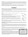
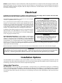
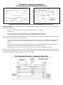
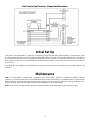
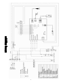
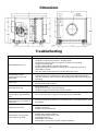
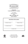
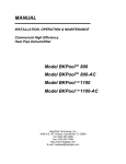
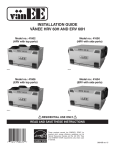
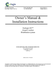
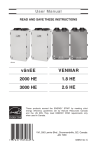
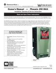
Installation, Operating
and Maintenance Manual
Model: DH-130A
Table of Contents
Page
Safety
.
.
Specifications .
.
.
.
.
.
.
.
.
.
.
.
.
.
.
.
.
.
2
.
.
.
.
.
.
.
.
.
.
.
.
.
.
.
.
.
3
Operation .
.
.
.
.
.
.
.
.
.
.
.
.
.
.
.
.
.
.
3
Installation
.
.
.
.
.
.
.
.
.
.
.
.
.
.
.
.
.
.
4
Electrical .
.
.
.
.
.
.
.
.
.
.
.
.
.
.
.
.
.
.
5
.
.
.
.
.
.
.
.
.
.
.
.
.
.
.
.
.
8
.
.
.
.
.
.
.
.
.
.
.
.
.
.
.
.
.
9
.
.
.
.
.
.
.
.
.
.
.
.
.
.
.
.
.
9
Initial Set Up .
Maintenance
.
Wiring Diagram
Dimensions
.
.
.
.
.
.
.
.
.
.
.
.
.
.
.
.
.
.
9
Parts Listing
.
.
.
.
.
.
.
.
.
.
.
.
.
.
.
.
.
.
10
Warranty .
.
.
.
.
.
.
.
.
.
.
.
.
.
.
.
.
.
.
11
.
.
.
.
.
.
.
.
.
.
.
.
.
.
.
.
.
12
Troubleshooting
Safety Instructions
Read and save these important safety instructions.
The installation, operation and maintenance instructions must be carefully followed while installing and operating the
dehumidifier. Proper adherence to these instructions is essential to obtain maximum benefit from your dehumidifier.
DANGER
•
•
120 volts may cause serious injury from electric shock. Disconnect electrical power before installation or servicing.
If used near a pool or spa; be certain there is no chance the unit could fall into the water or be splashed. Unit must be
grounded electrically in compliance with the National Electric Code and local codes. Failure to comply with this
warning could result in severe personal injury or death.
WARNING - CAUTION
•
This dehumidifier must be installed and serviced by a qualified heating, ventilation, and air conditioning professional in
compliance with all local and national codes. Improper installation, adjustment, alteration, service or maintenance can
cause injury or property damage.
•
•
Handle unit with care using adequate manpower or equipment to lift and avoid injury to personnel and/or equipment.
•
•
This unit is designed to be installed indoors in an area protected from rain or moisture.
•
•
For proper operation, external static pressures across the unit must not exceed .6 inches w.c.
Failure to install this dehumidifier in compliance with the instructions contained herein could result in unsatisfactory
operation and/or damage to the product.
It is recommended a drain pan be placed under the unit if installed above a living area or above an area where water
leakage could cause damage.
For protection of the compressor, it must be transported and installed in an upright position. If the unit was shipped or
stored on its side, a 24-hour settling period in the upright position is required before running the unit for the first time.
Temporary storage must be indoors, upright in the original carton, and completely shielded from precipitation.
2
Specifications
Capacity
130 Pints per day @ 80°F DBT / 60% RH
Unit Power Supply
115 Volts/Single Phase / 60 Hz
Minimum Circuit Ampacity
13.1
Maximum Fuse
15 amp
Overall Length 30” (includes duct collars)
Cabinet Length: 24”
Dimensions
Cabinet Width: 25¼”
Cabinet Height: 20½”
150 Pounds
Weight
Rotary Type
Compressor
1070 Watts / 9.5 RLA / 61 LRA
Refrigerant
R22
Fan Motor
.1 HP / 1.15 FLA
Air Flow
400 CFM @ .6 inches w.c. ESP
Filter
Washable Nylon / 17 x 23½”
Type EPDM / 1” thick
Cabinet Insulation
R Value / 4.2
Duct Connections
8” diameter
Drain Connections
¾” Primary and Secondary
Drain Pan
Stainless Steel
All specifications and performance data are subject to change without notice.
Operation
The function of the DH-130A dehumidifier is to reduce the indoor humidity levels and increase comfort. It is a high capacity
dehumidifier able to remove 130 pints of water per day (80°F DBT/60% RH). A humidity sensor (dehumidistat) senses when the
relative humidity (RH) is above the set point (example: 50% RH) and signals the dehumidifier to operate until the relative
humidity level has been lowered to the set point.
If the room thermostat calls for heating or cooling, the dehumidifier will stop and will not operate. When the room thermostat is
satisfied and the heating or air conditioner is stopped, the dehumidifier will resume operation if the relative humidity (RH) is
above the set point. If the dehumidistat is satisfied when the heating or cooling ceases, the dehumidifier will remain stopped.
If the switch on the thermostat for the heating or air conditioning system is placed in the OFF position, the dehumidifier will still
operate if the relative humidity is above the dehumidistat set point. To turn off the dehumidifier, move the dehumidistat dial to
the OFF position. Turning the dehumidifier off is not recommended as it reduces the effectiveness of the overall dehumidification
system.
Controls
Unit-Mounted Dehumidistat. The unit is controlled by the integral control system which operates the internal fan
approximately 15 minutes each hour to sample the air in the system. The air sample passes over the unit-mounted humidity
sensor which should be set at approximately mid-level. After a three minute delay, if the humidity level in the sampled air is
greater than the set point, the dehumidifier will turn on. The dehumidifier will operate until the humidity level reaches the
humidity sensor/set point.
Optional Wall-Controlled Dehumidistat. When the wall-controlled dehumidistat is used, the unit-mounted control must be set
to the lowest relative humidity (RH) setting and never readjusted. The wall-controlled dehumidistat should be set in the comfort
area of approximately 50% relative humidity. When the dehumidistat senses that the relative humidity in the space is above its
set point, an electrical contact within the dehumidistat closes causing the dehumidifier to start. The unit dehumidifier operates
until the relative humidity has been lowered to the set point.
3
Frost Control. In some cases of prolonged operation or if the conditioned space is relatively cool, frost will accumulate on the
coil. Ice may eventually cover the coil, block the air flow and stop proper operation. If the coil becomes unacceptably cold for at
least ten minutes, a sensor mounted on the coil will stop the compressor. To prevent frost build-up beyond an acceptable level,
the fan will continue to operate to melt any accumulated ice. Once the ice has melted and the coil is warm, the compressor will
restart and the dehumidification process will resume.
Float Switch. In addition to the primary and secondary condensate drain lines, the DH-130A is equipped with a float switch. If
the drain lines should become clogged or restricted, overflow of water will occur. This switch disables the compressor and stops
water production. Once the blockage has been cleared, the switch will allow the unit to return to normal operation.
Installation
Location. When choosing an installation location, consider the accessibility for service, condensate drain availability and power
connection. The proper location is very important as it will determine the overall length of the connection ducts. Locate the unit
as close as possible to the indoor portion of the heating or air conditioning system. The dehumidifier may be placed above, below
or level with the heating or air conditioning system.
Place the unit in a location that will allow a minimum of 22" clearance for filter removal and service access. This clearance is
required on only one side of the unit since the filter is removable from either side. Allow adequate clearance to walls for unit
service.
This humidifier is designed to be installed indoors in a space that is protected from rain or
moisture.
Suspended unit utilizing
optional hanging kit
Mounting. The dehumidifier may be mounted on a flat surface or suspended.
Do not mount the unit directly on structural members.
If mounted on a flat surface, use the four rubber mounting feet provided. To minimize unwanted
vibration, select a level mounting surface. Adjust the mounting feet to compensate for any surface
irregularities. Make certain that the unit is sitting on all four mounting feet.
To suspend the unit, a separate hanger kit (HD14) is required. This kit consists of four brackets and
four rubber isolators. Threaded rods or other means of suspension must be provided by the
installer and must be selected based on the unit weight (150 lbs.) and in compliance with local
codes.
This unit is equipped with a primary and secondary drain, along with a float switch to prevent
overflow of water from the unit. It is recommended a drain pan be placed under the unit if installed above a living area or above
an area where water leakage could cause damage.
Condensate Drain. The DH-130A is equipped with primary and secondary condensate drain line connections. The drains must
be trapped external to the unit and connected per national and local plumbing codes to drain lines that will carry away the water
collected by the dehumidifier.
To prevent water being removed from the traps when the air conditioning unit is running, the trap dimensions must be
equivalent to the dimension of the trap on the associated air conditioning system. The primary and secondary drain lines must be
attached to the trap outlets and pitched away from the unit a minimum of 1/8" per foot to assure proper water removal. It is
recommended a drain pan be placed under the unit if installed above a living area or above an area where water leakage could
cause damage.
The primary condensate drain must be routed according to national and local codes. The secondary condensate drain line must
discharge to a visible location to alert the end user that a problem exists with dehumidifier’s primary drainage system.
Ducting. The unit is furnished with two beaded 8" round collars for duct connections to
the inlet and the outlet of the dehumidifier. These are located inside the unit and must
be attached to the unit by the installer using screws and gaskets or caulking. Center the
collars over the inlet and outlet openings in the cabinet.
Insulated flexible ducts in compliance with Underwriter’s Laboratory’s (UL) Standard for
Factory Made Duct Materials, UL-18 and installed per the duct manufacturer’s
recommendation should be used to connect the dehumidifier to the heating or air
conditioning system. The installation and connections must be in compliance with
national and local codes and be completely tight and leak free. Ducts should be as short
as possible, not to exceed 100 ft. equivalent length and supported in compliance with
the duct manufacturer’s recommendation.
4
CAUTION!
All duct connections must be
sealed. Any air leakage in the
duct work will adversely affect
the operation of the
dehumidifier and may lead to
unsatisfactory performance.
Dampers. Optional dampers may be installed in the outlet duct, inlet duct or in an outside air duct. These dampers must be a fullflow motorized type. Do not use any type of pressure operated damper as unacceptable pressure drop will affect unit operation.
All dampers must be installed in compliance with the damper manufacturer’s recommendations and be insulated and sealed per
the section on ducting above.
Electrical
Installation must be performed by a qualified service technician and must comply with all national and local codes.
Remove power to the device before installing or servicing the equipment.
The electrical supply requirements are listed on the unit nameplate
and in the “Specification Table” on page 3.
Use a separate fused branch electrical circuit containing a properly
sized fuse or circuit breaker. Run this circuit directly from the main
circuit box to an electrical disconnect which must be readily accessible
and located within sight of the dehumidifier. Connect the disconnect
to the electrical connections inside the dehumidifier utilizing the hole
sized for 1/2" conduit provided on the entering-air-end of the unit.
Installation of the electrical supply line must be in accordance with the
National Electric Code, ANSI/ NFPA No. 70, latest edition, or Canadian
Electrical Code Part 1-CSA Standard C22.1 and local building/electric
DANGER
Turn off electrical power at the fuse or
service panel before making any electrical
connections. The ground connection must
be completed before making line voltage
connections. Failure to do so can result in
electrical shock, severe personal injury or
death. The dehumidifier must be installed
so that the electrical components are
protected from water from any source.
codes, using copper conductors only.
WARNING
Optional Remote Dehumidistat. The dehumidifier is supplied with its
L (hot) and N (neutral) polarity must be
own, self-contained dehumidistat which includes an air sampling
observed when making the electrical
sequence. The unit may also be controlled by a remote dehumidistat
connection to the unit.
located in a conditioned space. Do not locate the remote dehumidistat
in the ductwork. It is recommended that the remote dehumidistat be
located in an area close to the heating or air conditioning system thermostat, out of drafts, away from heat sources and out of
direct sunlight. It should be located approximately five feet above the floor in an area with good air circulation at an average
temperature and relative humidity.
Remove the jumper on terminals S1 and S2 and connect the remote dehumidistat as shown on the unit connection diagram.
DANGER
The cabinet must be permanently grounded. Connect the ground wire to the ground terminal provided
in the unit. Failure to ground the cabinet can result in fire, electrical shock, personal injury or death.
Installation Options
The dehumidifier may be installed so that the dehumidifier and the central heating or air conditioning system fans operate
separately of each other (Independent Operation) or may be connected requiring the dehumidifier and the central heating or air
conditioning system fans operate at the same time (Dependent Operation).
Independent Operation
Duct Connections. In this arrangement, the dehumidifier is connected across or in parallel with the heating or air conditioning
system. The discharge of the dehumidifier is connected to the discharge of the heating or air conditioning system. The inlet
connection of the dehumidifier is connected to the inlet duct of the heating or air conditioning system. When the dehumidifier is
connected for independent operation, the heating or air conditioning system fan and the dehumidifier fan will not operate at the
same time.
5
Dehumidifier Connected the Heating or
Air Conditioning System Piped Parallel to System
Ceiling/Floor Joists
Supply Air
Heating or Air Conditioning System (Top
View)
Return Air
Supply
Air
Dehumidifier
Optional N.C.
Damper
Return
Air
Dehumidifier
Heating or Air
Conditioning
System (Top
View)
Dehumidifier
Suspended from
Ceiling
Optional N.C. Damper
Heating or Air Conditioning System Blower and Dehumidifier DO NOT Operate at the Same Time
Controls Connection. The dehumidifier controls must interface with the heating or air conditioning system. This interface is
required to do the following:
•
Turn off the dehumidifier if the heating or air conditioning system is in the cooling or
heating mode.
•
Turn off the heating or air conditioning system fan during dehumidifier operation if the FAN
switch on room thermostat has been placed in the ON position for continuous operation.
Five wires run from the heating or air conditioning system to the dehumidifier. To accomplish this independent operation interface,
see the “Unit Connection Diagram” and the following:
•
Connect the C, W and Y terminals on the dehumidifier to the corresponding terminals on the heating or air conditioning
system. Do not disconnect any of the existing wires from the C, W or Y terminals on the heating or air conditioning
system.
•
Disconnect the existing thermostat wire from the G terminal on the heating or air conditioning system. Using a wire nut,
splice this wire to a new wire and then connect to the G1 terminal on the dehumidifier.
•
Connect the G2 terminal on the dehumidifier to the G terminal on the heating or air conditioning system.
All controls wiring, including connection to a remote dehumidistat must be 18-22 gauge and meet national and local electrical
codes. Entry into the dehumidifier is through a 7/8" diameter hole located on the air-entry-end of the dehumidifier, adjacent to the
unit-mounted dehumidistat. Note: This is separate from the power entry.
Unit Connection Diagram – Independent Operation
6
Damper Connection. If an optional damper(s) is used in the discharge/return duct, this may be controlled by the dehumidifier.
See “Unit Connection Diagram - Independent Operation”, above for connection details. When connected as shown in the above
diagram, the dehumidifier provides only the switching interface for the damper(s). Power for these devices must be provided
with a separate transformer (not provided), not from the transformer located in the dehumidifier.
The damper control wiring must meet national and local electrical codes. Entry into the dehumidifier is through the control wire
entry located on the air-entry-end of the unit. Note: This is separate from the power entry.
Dependent Operation
Duct Connections. In this arrangement, the dehumidifier is connected either upstream or downstream of the heating or air
conditioning system. Both the discharge and the return of the dehumidifier are connected to the same side of the system. When
the dehumidifier is connected for dependent operation, the heating or air conditioning system fan and the dehumidifier fan must
operate at the same time.
Dehumidifier Connected for Dependent Operation
with Heating or Air Conditioning System Piped Return/Return
Discharge
Air
Heating or Air
Conditioning
System
(Top View)
Return
Air
8” Max
Dehumidifier
Installed on
Floor
Heating or Air Conditioning System Blower and Dehumidifier MUST Operate at the Same Time
Controls Connection. The dehumidifier controls must interface with the main heating or air conditioning system. This interface
is required to ensure that the heating or air conditioning system fan is on when the dehumidifier is operating.
Two wires run from the heating or air conditioning system to the dehumidifier. To accomplish this dependent operation, use the
interface “Unit Connection Diagram – Dependent Operation” below and the following:
•
Connect the D terminals on the dehumidifier to the R terminal on the heating or air conditioning system.
Do not disconnect any of the existing wires from the heating or air conditioning system.
•
Connect the DH terminal on the dehumidifier to the G terminal on the heating or air conditioning
system. Do not disconnect any of the existing wires from the heating or air conditioning system.
All controls wiring, including connection to a remote dehumidistat must be 18-22 gauge and must meet national and local
electrical codes. Entry into the dehumidifier is through a 7/8" diameter hole located on the air-entry-end of the unit, adjacent to
the unit-mounted dehumidistat. Note: This is separate from the power entry.
Damper Connection. Although not necessary, if an optional damper(s) is utilized in the discharge/return duct, this may be
controlled by the dehumidifier. See the “Unit Connection Diagram – Dependent Operation” below for connection details. When
connected as shown in the “Unit Connection Diagram,” the dehumidifier provides the switching interface for the damper(s) as
well as the line voltage power to the transformer (not included). Power for the damper(s) is provided by the dehumidifier.
The damper control wiring must meet national and local electrical codes. Entry into the dehumidifier is through the control wire
entry located on the air-entry-end of the unit. Note: This is separate from the power entry.
7
Unit Connection Diagram – Dependent Operation
Initial Set Up
Turn power to the dehumidifier on. Adjust the set point knob to approximately 60% relative humidity. For wall-controls, adjust
the unit-mounted control to its minimum relative humidity (RH) setting and set the wall-mounted dehumidistat to a desired level.
It is recommended that it first be set to approximately 60% RH and then adjusted, no sooner than 24 hours later, to a higher or
lower set point as desired. It is recommended that all adjustments be made in no more than 3% increments at no less than 24
hour intervals.
Depending upon the conditions, the dehumidifier may operate for extended periods, especially when first started or after having
been off.
Maintenance
Filter. The dehumidifier is equipped with a permanent nylon mesh air filter. This filter is washable and should be cleaned
regularly. It is recommended to clean the humidifier filter at the same time the heating or air conditioner filter is replaced. If the
filter has become excessively dirty when cleaned at this interval, it may be necessary to adjust the cleaning schedule to more
frequent cleaning. Excess dirt on the filter will reduce overall effectiveness of the dehumidifier.
Drain. The drain trap or outlet should be checked and cleaned annually. Flush it with water to ensure the drain is clear.
8
9
Dimensions
Troubleshooting
PROBLEM
•
•
•
Dehumidifier will not run.
•
•
•
POSSIBLE SOLUTION
Verify there is power to the unit.
Check that any disconnect switch is in the ON position.
Check that the circuit breaker is not tripped (a separate 15 amp circuit
breaker is recommended).
Verify the dehumidistat is not in the OFF position.
Verify low voltage wiring between heating and air conditioning system and
dehumidifier is correct.
Unit door switch is not mechanically actuated due to loose door.
Dehumidifier operates
continuously but does not
dehumidify.
• Filter may be dirty. Clean filter.
• Dehumidistat set at unrealistically low setting. Reset to approximately 50% RH.
• Unit will need time to “dry” materials in the building before effectively changing the
RH setting.
Unit is noisy.
• Ensure unit is sitting level and on all four feet.
• Verify all panel screws are tight.
Water drips from unit.
• Ensure unit is level.
• Verify condensate drain is properly trapped.
• Check for plugged condensate trap or condensate line.
Heating or air conditioning
system is OFF, but dehumidifier
runs.
•
This is normal operation as long as there is power to the dehumidifier.
•
Check low voltage wiring between air conditioning unit C, Y and W terminals and the
dehumidifier.
Compressor never runs.
•
•
•
Confirm that the float switch is not stuck open.
Defective compressor.
Defective control circuit board.
Unit removes some water, but
not as much as expected.
•
•
•
•
•
•
Air temperature or humidity has dropped.
Air filter dirty or airflow restricted.
Defective defrost thermostat in unit.
Low refrigerant charge.
Dehumidifier coils are dirty.
Air leak such as a loose cover or panel or leaks in ductwork.
Dehumidifier continues to run
when heating or air conditioning
system runs.
10
Replacement Parts
Item
Part Number
1
DHD114
DHVB14
DHBM14
DHMT14
DHBW14
DHRC14
DHDP14
DHSM14
DHCO14
DHFT14
DHUF14
DHDR14
DHTR14
DHVR14
DHLF14
DHSR14
DHTX14
DHCS14
2
3
4
5
6
7
8
9
10
11
12
13
14
15
16
17
19
Description
Duct, Supply
Panel, Blower Supply w/Insulation
Base, Motor
Motor, 115V, 1/10 HP, 3 Speed
Blower Set (Wheel/Housing/Inlet)
Capacitor (Motor)
Drain Pan
Panel Side with Insulation
Coil
Filter, 431x595x5mm, Nylon
Filter, Upper Groove
Duct, Return
Transformer, 115-24VAC, 24 VA
Panel, Return Air with Insulation
Filter, Lower Groove
Support, Side Panel Return Air
TEX Valve
Compressor
Item
Part Number
20
21
22
23
24
25
26
27
28
29
DHBT14
DHSD14
DHSP14
DHPP14
DHHC14
DHNC14
DHRI14
DHAF14
DHDS14
DHCT14
DHMH14
DHRH14
DHTP14
DHHG14
DHTS14
DHTS14-1
DHRC14-1
DHDF14
30-31
32
33
34
35
36
37
38
11
Description
Bottom Pan
Panel, Side with Insulation
Panel, Filter with Insulation (2 Required)
PCB, Main
Sensor Module, Humidity with Harness
Knob, Control
Isolator, Rubber (4 Required)
Foot, Rubber, Adjustable (4 Required)
Switch, Door
Panel, Control
Grommet, Rubber, Closed, 7/8" OD
Pot, RH Adjustment with Harness
Panel, Top with Insulation
Hanger (4 Required)
Terminal Strip, TB-10, 5 Amp
Terminal Strip, TB-6, 30 Amp
Capacitor (Compressor)
Defrost Sensor with Harness
Warranty
Full (One Year) Parts Warranty. All parts of the dehumidifier are warranted to be free from defects for one year from the date of
purchase by the original consumer when installed per the installation instructions and in accordance with all local, state, and
national codes for normal residential use.
Limited Five Year Compressor Only Warranty. In addition to the full (one year) parts warranty described above, we will
exchange the compressor during the second year through fifth year from the original date of purchase, providing the compressor
is defective in material or workmanship.
Transportation, handling, and labor costs to diagnose, repair or replace such defective parts are not covered by this limited parts
warranty and are the owner's responsibility. Ready access to the unit for service is the responsibility of the owner.
NOTE: In the event of any required parts replacement within the period of this warranty, replacement parts shall be furnished and
will be warranted only for the period remaining on the original warranty.
Exceptions. The warranty does not cover normal maintenance, labor charges, transportation charges for replacement parts,
replacement of refrigerant or filters, any other service call or repairs. Other than for residential use, if the unit is put into
commercial, business, rental or other use or application, we make no warranties, express or implied. We will not be liable for
damages or delays caused by events beyond our control, including accident, alteration, abuse, war, government restrictions,
strikes, fire, flood or other acts of God.
Duration of Warranty. The warranty begins on the date of purchase by the original consumer. The consumer must provide a
receipted bill of sale as proof of warranty period. Without this proof, the warranty begins on date of shipment from the factory.
1.
There are no other express or implied warranties or any warranty of merchantability. We do not warrant that the unit is
suitable for any particular purpose or can be used in buildings or rooms of any particular size or condition except as
specifically provided in this document. There are no other warranties, express or implied, which extend beyond the
description in this document.
2.
All warranties implied by law are limited in duration to the one year (parts) or five year (compressor) terms of the
warranty. Your exclusive remedy is limited to the replacement of defective parts and compressor. We will not be liable
for any damages caused by any defect in this unit.
Some states do not allow limitation on how long an implied warranty lasts or do not allow the exclusion or limitation of
incidental or consequential damages, so the above limitation or exclusions may not apply to you.
3.
No warranties are made for units sold outside the continental United States and Canada. Your distributor or final seller
may provide a warranty on units sold outside these areas.
How to Obtain Warranty Service or Parts. If you have a warranty claim, notify your installer promptly. If within a reasonable
time after contacting your installer, satisfactory service has not been received, contact:
Customer Service, 250 West Laurel Street, Colton, California 92324 U.S.A.
Enclose a report of inspection by your installer or service person. Include the model number, serial number, and date of purchase.
Owner responsibilities are set forth in the instruction manual. Read it carefully.
250 West Laurel Street • Colton, California 92324 U.S.A.
www.e-wfc.com ● Telephone: (909) 825-0993
Subject to Change without Notice
12
March 2007