1
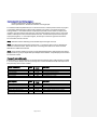
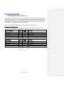
GE MDS, LLC. NETio Series Protocol Communications Supplement March 2013 Part No. 05-4672A01, Rev. C Modbus Protocol NETio Architectural Implementation As described in detail below, the Modbus RTU protocol is a master/slave protocol. Within a given Modbus network scheme, a NETio unit (or Base Module) and its associated Expansion Modules acts as a single slave device. Once the Modbus slave address is configured at a Base Module, that address applies to all of the I/O on that particular module and its expansion modules. The “memory map” for that slave address includes both the base and expansion I/O. A NETio Base Module will process Modbus messages that come from one of two sources depending upon how the user has configured it: a) The source is over-the-air from an EntraNET AP. This method allows a NETio Base Module to wirelessly communicate with a MODBUS Master device or system via the entraNET Access Point. The Access Point is where the physical connection to the MODBUS host is made. The connection can be serial or TCP-Modbus; see the NETio Manual for instructions on how to configure these options. b) The source is local. This method allows a NETio Base Module to communicate with a Modbus Master device or system physically connected to the serial communication port on the NETio Base Module. See the NETio Manual for instructions on how to configure these options. Electrical Interface (Access Point) The hardware or electrical interface is either the COM1 (RJ11) or COM2 (RJ45) RS232 connections on the front faceplate of the Access Point module. Data flow is half-duplex. That is, data is never transmitted and received at the same time. Shielded wire should always be used to minimize noise. Refer to the EntraNET Access Point User Manual for correct serial port wiring. Electrical Interface (NETio Base Module) The hardware or electrical interface is the COM1 (RJ45) RS232 connection on the front panel of the NETio module. Data flow is half-duplex. That is, data is never transmitted and received at the same time. Shielded wire should always be used to minimize noise. Refer to the NETio User Manual for correct serial port wiring. Modbus RTU Description The NETio implements a subset of the Modicon Modbus RTU serial communication standard. Many popular programmable controllers support this protocol directly with a suitable interface card allowing direct connection to an Access Point. Modbus is a single master, multiple slave protocol. The NETio is always a slave; it cannot be programmed as a master. Computers or PLCs are commonly programmed as masters. The Modbus protocol exists in two versions: Remote Terminal Unit (RTU, binary) and ASCII. NETio supports the RTU version only. Monitoring, programming, and control functions are performed with read/write register commands. Data Frame Format and Data Rate One data frame of an asynchronous transmission to or from a NETio system (consisting on an Access Point with one or more NETio modules) is defaulted to 1 start bit, 8 data bits, and 1 stop bit. This produces a 10-bit data frame. The parity bit is optional as odd or even. If it is programmed as odd or even, the data frame consists of 1 start bit, 8 data bits, 1 parity bit, and 1 stop bit. Modbus protocol can be implemented at any standard communication speed. The Access Point’s COM ports support operation at 1200, 2400, 4800, 9600, 19200, 38400, 57600 and 115200 baud. Page 2 of 23 Data Packet Format A complete request/response sequence consists of the following bytes (transmitted as separate data frames): 1. A Master Query Message consisting of: a 1-byte Slave Address, a 1-byte Function Code, a variable number of Data Bytes depending on the Function Code, and a 2-byte CRC code. 2. A Slave Response Message consisting of: a 1-byte Slave Address, a 1-byte Function Code, a variable number of Data Bytes depending on the Function Code, and a 2-byte CRC code. The terms Slave Address, Function Code, Data Bytes, and CRC are explained below: • SLAVE ADDRESS: This is the first byte of every transmission. This byte represents the userassigned address of the slave device that is to receive the message sent by the master. Each slave device (or NETio Base Module, in this case) must be assigned a unique address and only the addressed slave will respond to a transmission that starts with its address. In a master request transmission the Slave Address represents the address of the slave to which the request is being sent. In a slave response transmission the Slave Address represents the address of the slave that is sending the response. Note: A master transmission with a Slave Address of 0 indicates a broadcast command. Broadcast commands can be used for specific functions. • FUNCTION CODE: This is the second byte of every transmission. Modbus defines function codes of 1 to 127. The NETio implements some of these functions. In a master request transmission the Function Code tells the slave what action to perform. In a slave response transmission if the Function Code sent from the slave is the same as the Function Code sent from the master indicating the slave performed the function as requested. If the high order bit of the Function Code sent from the slave is a 1 (i.e. if the Function Code is greater than 127) then the slave did not perform the function as requested and is sending an error or exception response. • DATA BYTES: This is a variable number of bytes depending on the Function Code. These may be actual values, setpoints, or addresses sent by the master to the slave or vice-versa. Data is sent MSByte first followed by the LSByte. • CRC: This is a two byte error checking code. CRC is sent LSByte first followed by the MSByte. The RTU version of Modbus includes a two byte CRC-16 (16-bit cyclic redundancy check) with every transmission. The CRC-16 algorithm essentially treats the entire data stream (data bits only; start, stop and parity ignored) as one continuous binary number. This number is first shifted left 16 bits and then divided by a characteristic polynomial (11000000000000101B). The 16-bit remainder of the division is appended to the end of the transmission, LSByte first. The resulting message including CRC, when divided by the same polynomial at the receiver will give a zero remainder if no transmission errors have occurred. If a NETio Modbus slave device receives a transmission in which an error is indicated by the CRC-16 calculation, the slave device will not respond to the transmission. A CRC-16 error indicates than one or more bytes of the transmission were received incorrectly and thus the entire transmission should be ignored in order to avoid the NETio performing any incorrect operation. The CRC-16 calculation is an industry standard method used for error detection. An algorithm is included here to assist programmers in situations where no standard CRC-16 calculation routines are available. Page 3 of 23 CRC-16 Algorithm Once the following algorithm is complete, the working register “A” will contain the CRC value to be transmitted. Note that this algorithm requires the characteristic polynomial to be reverse bit ordered. The MSbit of the characteristic polynomial is dropped since it does not affect the value of the remainder. The symbols used in the algorithm are shown below: --> data transfer A; A low; A high 16-bit working register; low and high order bytes of A (the 16-bit working register) CRC 16 bit CRC-16 result i, j loop counters (+) logical EXCLUSIVE-OR operator N total number of data bytes Di i-th data byte (i = 0 to N – 1) G 16 bit characteristic polynomial = 1010000000000001 (binary) with MSbit dropped and bit order reversed shr (x) right shift operator (the LSbit of x is shifted into a carry flag, a '0' is shifted into the MSbit of x, all other bits are shifted right one location) The CRC algorithm is shown below: 1. 2. 3. 4. 5. 6. 7. FFFF (hex) --> A 0 --> i 0 --> j Di (+) Alow --> Alow j + 1 --> j shr (A) Is there a carry? 8. 9. 10. 11. Is j = 8? i + 1 --> i Is i = N? A --> CRC No: go to step 8. Yes: G (+) A --> A and continue. No: go to 5.; Yes: continue. No: go to 3.; Yes: continue. Error Responses As with any communications scheme, errors can occur. When a NETio detects an error other than a CRC error, a response will be sent to the master. The MSbit of the Function Code byte will be set to 1 (i.e., the function code sent from the slave will be equal to the function code sent from the master plus 128). The following byte will be an exception code indicating the type of error that occurred. Transmissions received from the master with CRC errors will be ignored by the NETio. The slave response to an error (other than a CRC error) will be: FUNCTION CODE: 1 byte (with MSbit set to 1) EXCEPTION CODE: 1 byte CRC: 2 bytes Page 4 of 23 NETio implements the following exception response codes… 01: ILLEGAL FUNCTION The function code transmitted is not supported by NETio. 02: ILLEGAL DATA ADDRESS The address referenced in the data field transmitted by the master is not allowable for the NETio. NETio Memory Map (Point Addressing) Within the scope of a Modbus network, a NETio Base Module along with its Expansion Modules will appear as a single device. Because of this, all of the associated I/O, regardless of what physical device the actual point is on, must translate into a single memory map. The Modbus RTU protocol supports a 16-bit addressing scheme, ranging from 0x0000 to 0xFFF. The NETio usage of this addressing range is such that the upper byte designates the I/O module ID, and the lower byte designates the individual I/O point (starting at address 0). 0x # # # Module ID # Point For example, when referencing Input 1 on an Expansion Module with the ID configured to 15, the memory address would be 0x0F00, the MODBUS address would be 0x0F01 or 3841. Note that the I/O Module ID for a base module is always 0. NOTE: A simple way to calculate a Modbus address for NETio in decimal format is as follows: Multiply the Module ID by 256. This moves the Module ID to the upper byte of a 16-bit word. Then add the I/O point number. NOTE: The calculated MODBUS address may need to be decreased by 1 if the MODBUS master uses 0-based addressing. As an addressing example, Analog Input # 2 on Module ID # 3 would be as follows: Module ID 3 * 256 = 768 Analog Input 2 = 2 Modbus address in decimal = 768+2 = 770 Refer to the following table for a list of commonly used Module ID numbers and their associated addresses. Module ID # >> st Hex value 1 I/O I/O Point # st 1 I/O nd 2 I/O rd 3 I/O th 4 I/O th 5 I/O th 6 I/O 0 0x0001 1 0x0101 2 0x0201 3 0x0301 4 0x0401 5 0x0501 6 0x0601 Etc… Etc… 1 2 257 258 259 260 261 262 513 514 515 516 517 518 769 770 771 772 773 774 1025 1026 1027 1028 1029 1030 1281 1282 1283 1284 1285 1286 1537 1538 1539 1540 1541 1542 Etc… Etc… Etc… Etc… Etc…. Etc… Page 5 of 23 Modbus Functions Supported Functions The NETio System supports the following functions: Function Code 01: Function Code 02: Function Code 03: Function Code 04: Function Code 05: Function Code 06: Read Coils Read Discrete Inputs Read Holding Registers Read Input Registers Write Single Coil Write Single Registers A detailed explanation of how the NETio implements these function codes is shown in the following sections. Function Code 01: Read Coils Modbus implementation: Read Coils NETio Implementation: Read Present Value of a Discrete Output For the NETio Modbus implementation, this command is used to read the present value of any single or consecutively addressed discrete output points in the system. The request specifies the starting address, i.e. the address of the first output point specified, and the number of output points requested. The slave response to this function code is the slave address, function code, a count of the number of data bytes to follow, the data itself and the CRC. The data itself, represented as 1=ON and 0=OFF, is packed as one output point per bit. The LSB of the first data byte contains the state of the output point addressed in the request. The CRC is sent as a two byte number with the low order byte sent first. NOTE: Remember that the addressing of the individual I/O points begins at zero (0). NOTE: Due to the NETio addressing scheme, a single Read Coils message will not be able to query the state of a group of outputs that spans multiple NETio modules. A separate query will be needed for each NETio module. Message Format and Example: Request slave 11 to respond with the current state of Discrete Outputs 3, 4 and 5 of NETio Expansion Module 2. For this example, all of the Outputs in question have been previously energized: Master Transmission Slave Address Function Code Starting Address Quantity of Coils CRC (low, high) Bytes 1 1 2 2 2 Example (hex) 0B 01 02 02 00 03 TBD Page 6 of 23 Description Message for slave 11 (NETio Base w/ address 11) Read coils I/O module 2, Discrete Output 3 3 discrete outputs Computed CRC error code Slave Response Slave Address Function Code Byte Count Coil Statuses CRC (low, high) Bytes 1 1 1 1 2 Example (hex) 0B 01 01 07 TBD Description Message from slave 11 (NETio Base w/ address 11) Read coils One byte needed Packed output statuses (0000 0111) Computed CRC error code Function Code 02: Read Discrete Inputs Modbus implementation: Read Discrete Inputs NETio Implementation: Read Present Value of a Discrete Input For the NETio Modbus implementation, this command is used to read the present value of any single or consecutively addressed discrete input points in the system. The request specifies the starting address, i.e. the address of the first input point specified, and the number of input points requested. The slave response to this function code is the slave address, function code, a count of the number of data bytes to follow, the data itself and the CRC. The data itself, represented as 1=ON and 0=OFF, is packed as one input point per bit. The LSB of the first data byte contains the state of the input point addressed in the request. The CRC is sent as a two byte number with the low order byte sent first. NOTE: Remember that the addressing of the individual I/O points begins at zero (0). NOTE: Due to the NETio addressing scheme, a single Read Discrete Inputs message will not be able to query the state of a group of inputs that spans multiple NETio modules. A separate query will be needed for each NETio module. Message Format and Example: Request slave 11 to respond with the current state of Discrete Inputs 2 and 3 on the Base Module itself. For this example, both Inputs in question are energized: Master Transmission Slave Address Function Code Starting Address Quantity of Inputs CRC (low, high) Slave Response Slave Address Function Code Byte Count Input Statuses CRC (low, high) Bytes 1 1 2 2 2 Bytes 1 1 1 1 2 Example (hex) 0B 02 00 01 00 02 TBD Example (hex) 0B 02 01 03 TBD Page 7 of 23 Description Message for slave 11 (NETio Base w/ address 11) Read Discrete Inputs I/O module 0 (base), Discrete Input 2 2 discrete inputs Computed CRC error code Description Message from slave 11 (NETio Base w/ address 11) Read Discrete Inputs One byte needed Packed input statuses (0000 0011) Computed CRC error code Function Code 03: Read Holding Registers Modbus implementation: Read Holding Registers NETio Implementation: Read Present Value of an Analog Output For the NETio Modbus implementation, this command is used to read the present value of any single or consecutively addressed analog output points (registers) in the system. The request specifies the starting address, i.e. the address of the first output point specified, and the number of output points requested. The slave response to this function code is the slave address, function code, a count of the number of data bytes to follow, the data itself and the CRC. The data itself is packed as two bytes per output point (register). For each output register, the first byte contains the high order bits and the second contains the low order bits. NOTE: Remember that the addressing of the individual I/O points begins at zero (0). NOTE: The Analog Value returned will be in A/D Counts. To convert the value to volts or milliamps, the user must convert the number. Refer to the section “Converting NETio A/D Counts” at the end of this Addendum for additional information NOTE: Due to the NETio addressing scheme, a single Read Holding Register’s message will not be able to query the state of a group of outputs that spans multiple NETio modules. A separate query will be needed for each NETio module. Message Format and Example: Request slave 11 to respond with the current state of Analog Outputs 1and 2 of NETio Expansion Module 5. For this example, Output 1 has been previously set to a value of 32768 (half scale) while Output 2 has been previously set to a value of 10000: Master Transmission Bytes Slave Address Function Code Starting Address Quantity of Registers CRC (low, high) 1 1 2 2 2 Slave Response Slave Address Function Code Byte Count Register value #1 (high, low) Register value #2 (high, low) CRC (low, high) Bytes 1 1 1 2 2 2 Example (hex) 0B 03 05 00 00 02 TBD Example (hex) 0B 03 04 80 00 27 10 TBD Page 8 of 23 Description Message for slave 11 (NETio Base w/ address 11) Read Holding Registers I/O module 5, Analog Output 1 2 analog outputs = 4 bytes total Computed CRC error code Description Message from slave 11 (NETio Base w/ address 11) Read Holding Registers 4 bytes needed Value in address 0x0501, which is 32768 Value in address 0x0502, which is 10000 Computed CRC error code Function Code 04: Read Input Registers Modbus implementation: Read Input Registers NETio Implementation: Read Present Value of an Analog Input For the NETio Modbus implementation, this command is used to read the present value of any single or consecutively addressed analog input points (registers) in the system. The request specifies the starting address, i.e. the address of the first input point specified, and the number of input points requested. The slave response to this function code is the slave address, function code, a count of the number of data bytes to follow, the data itself and the CRC. The data itself is packed as two bytes per input point (register). For each input register, the first byte contains the high order bits and the second contains the low order bits. NOTE: Remember that the addressing of the individual I/O points begins at zero (0). NOTE: The Analog Value returned will be in A/D Counts. To convert the value to actual volts or milliamps, the user must convert the number. Refer to the section “Converting NETio A/D Counts” at the end of this Addendum for additional information NOTE: Due to the NETio addressing scheme, a single Read Input Registers message will not be able to query the state of a group of inputs that spans multiple NETio modules. A separate query will be needed for each NETio module. Message Format and Example: Request slave 11 to respond with the current state of Analog Inputs 2 and 3 of NETio Expansion Module 10. For this example, Input 2 has a value of 1000 and Input 3 has a value of 50300: Master Transmission Bytes Slave Address Function Code Starting Address Quantity of Registers CRC (low, high) 1 1 2 2 2 Slave Response Slave Address Function Code Byte Count Register value #1 (high, low) Register value #2 (high, low) CRC (low, high) Bytes 1 1 1 2 2 2 Example (hex) 0B 04 0A 01 00 02 TBD Example (hex) 0B 04 04 03 E8 C4 7C TBD Page 9 of 23 Description Message for slave 11 (NETio Base w/ address 11) Read Input Registers I/O module 10, Analog Input 2 2 analog outputs = 4 bytes total Computed CRC error code Description Message from slave 11 (NETio Base w/ address 11) Read Input Registers 4 bytes needed Value in address 0x0A02, which is 1000 Value in address 0x0A03, which is 50300 Computed CRC error code Function Code 05: Write Single Coil Modbus implementation: Write Single Coil NETio Implementation: Write to a Discrete Output For the NETio Modbus implementation, this command is used to set the value of any single discrete output point in the system. For this function, the requested ON/OFF state is specified by a constant in the Output Value field. A value of 0xFF00 requests the output to be ON, while a value of 0x0000 requests the output to be OFF. The slave response to this function code is the slave address, function code, the output address, the value written to the output and the CRC. NOTE: Remember that the addressing of the individual I/O points begins at zero (0). Message Format and Example: Request slave 11 to set the current state of Discrete Output 2 of NETio Expansion Module 5 to ON. Master Transmission Bytes Slave Address Function Code Output Address Output Value CRC (low, high) 1 1 2 2 2 Slave Response Bytes Slave Address Function Code Output Address Output Value CRC (low, high) 1 1 2 2 2 Example (hex) 0B 05 05 01 FF 00 TBD Example (hex) 0B 05 05 02 FF 00 TBD Page 10 of 23 Description Message for slave 11 (NETio Base w/ address 11) Write Single Coil I/O module 5, Discrete Output 2 Set output to ON Computed CRC error code Description Message from slave 11 (NETio Base w/ address 11) Write Single Coil I/O module 5, Discrete Output 2 Output set to ON Computed CRC error code Function Code 06: Write Single Register Modbus implementation: Write Single Register NETio Implementation: Write to an Analog Output For the NETio Modbus implementation, this command is used to set the value of any single analog output point (register) in the system. The slave response to this function code is the slave address, function code, the output address, the value written to the output and the CRC. NOTE: Remember that the addressing of the individual I/O points begins at zero (0). NOTE: The Analog Value written must be in NETio A/D Counts. To convert volts or milliamps to NETio Counts refer to the section “Converting NETio A/D Counts” at the end of this Addendum for additional information. Message Format and Example: Request slave 11 to set the current state of Analog Output 1 of NETio Base Module to a value of 16384 (1/4 range). Master Transmission Bytes Slave Address Function Code Output Address Output Value CRC (low, high) 1 1 2 2 2 Slave Response Bytes Slave Address Function Code Output Address Output Value CRC (low, high) 1 1 2 2 2 Example (hex) 0B 06 00 00 40 00 TBD Example (hex) 0B 06 00 00 40 00 TBD Page 11 of 23 Description Message for slave 11 (NETio Base w/ address 11) Write Single Register I/O module 0 (base), Analog Output 1 Set output to 16384 Computed CRC error code Description Message from slave 11 (NETio Base w/ address 11) Write Single Register I/O module 0 (base), Analog Output 1 Output set to 16384 Computed CRC error code Converting NETio A/D Counts All NETio Analog Input and Output values are represented internally in A/D counts. The actual value represented by the counts is based upon whether the analog point is configured as a current or voltage signal. 4-20 mA Signals For 4-20 mA current inputs or outputs the conversion factor is .000244. In addition, because the range of the signal is offset from zero (0) by 4 mA, the number 4 must be added to the converted number to get actual milliamps. Therefore: A count value of 31534 read from NETio equals: 31584 X .000244 = 7.70 milliamps 7.70 + 4.0 (Zero Offset) = 11.70 milliamps A Modbus command to generate a 12.6 milliamp would use the following count value: 12.6 Milliamps – 4.0 (Zero Offset) = 8.6 milliamps 8.6 / .000244 = 35246 counts 0-5 Volt and 0-10 Volt Signals For 0-5 Volt inputs and outputs the conversion factor is .000076. For 0-10 Volt I/O the conversion factor is .0001525. Since the range begins a zero (0) there is not offset needed. Therefore: A count value of 54320 read from NETio equals: For a 0-5 Volt Input: 54320 X .000076 = 4.13 Volts For a 0-10 Volt Input: 54320 X .0001525 = 8.28 Volts A Modbus command to generate a 3.4 Volt would use the following count value: For a 0-5 Volt Output: 3.4 / .000076 = 44737 counts For a 0-10 Volt Output: 3.4 / .0001525 = 22295 counts Page 12 of 23 DNP Protocol NETio Architectural Implementation As described in detail below, the DNP V3.00 protocol is a master/slave protocol. A NETio unit (or Base Module) and its associated Expansion Modules each have unique DNP addresses. Accessing all I/O points from a NETio unit will require separate DNP messages for the base and its expansions. A NETio Base Module will process DNP messages that come from one of three sources depending upon how the user has configured it. a) The source is over-the-air from an EntraNET AP. This method allows a NETio Base Module to wirelessly communicate with a DNP Master device or system via the entraNET Access Point. The Access Point is where the physical connection to the DNP host is made. The connection can be serial or DNP over UDP/TCP; see the NETio Manual for instructions on how to configure these options. b) The source is local. This method allows a NETio Base Module to communicate with a DNP Master device or system physically connected to the serial communication port on the NETio Base Module. See Local-Master-Mode, Protocol-Pass-Through and DirectMode in the NETio Manual for additional details. c) The source is over-the-air from a Direct Mode root or Direct Mode node. This method allows a NETio Base Module to wirelessly communicate with a DNP Master device or system via another NETio Base Module. One of the NETio Base Modules is where the physical connection to the DNP host is made (typically the DNP host would connect to the Direct Mode root). See Local-MasterMode, Protocol-Pass-Through and Direct Mode in the NETio Manual for additional details. Electrical Interface (Access Point) The hardware or electrical interface is either the COM1 and COM2 RS232 connections or the LAN Ethernet interface on the front faceplate of the Access Point module. Data flow is half-duplex. That is, data is never transmitted and received at the same time. Shielded wire should always be used to minimize noise. Refer to the EntraNET Access Point User Manual for correct serial and Ethernet port wiring. Electrical Interface (NETio Base Module) The hardware or electrical interface is the COM1 (RJ45) RS232 connection on the front panel of the NETio module. Data flow is half-duplex. That is, data is never transmitted and received at the same time. Shielded wire should always be used to minimize noise. Refer to the NETio User Manual for correct serial port wiring. Device Profile Document When configured as a DNP device, NETio Base Module must support the features listed in the Level 1 DNP V3.00 Implementation (DNP-L1) described in Chapter 2 of the subset definitions. See the DNP protocol website at http://www.dnp.org/ for details. NETio Point Addressing Within the scope of a DNP network, a NETio Base Module along with its Expansion Modules will appear as independent DNP devices (although communication with the expansions is only possible through the Base Module). In terms of DNP, each Base and Expansion has an independent and static I/O point list. To address a specific I/O point, DNP uses addresses, Object numbers, Variation numbers and Index numbers. The definition of Objects, Variations and Indexes are described in the DNP specifications. The details on how to access specific NETio I/O points will be discussed. Page 13 of 23 DNP uses 16-bit addressing, ranging from 0x0000 to 0xFFFF. The NETio usage of the unicast address range (0x0000 to 0xFFEF) is that the upper byte is common to a Base Module and it’s Expansions (call this the DNP Id of the NETio unit), while the lower byte is used to select the Base Module or a particular Expansion Module. The Base Module is addressed by using a lower byte value of 0x0 (zero), while Expansion Modules are addressed by using the module’s Id as the lower byte value. Note that only the base module is capable of responding to the DNP multicast addresses (0xFFF0 to 0xFFFF). 0x # # # Common Address # Module Id Each NETio module (Base or Expansion) acts as an independent DNP device, therefore I/O points start at index 0x0 (zero) for each module. Examples: A NETio Base Module has one Expansion Module of type 3 with an Id configured to 0x39. The NETio Base Modules has been configured to use the value 0x05 as the upper byte of DNP addresses (the DNP Id). In order to access digital output 1 on the NETio Base Module, send a DNP message with the following: DNP Destination Address 0x0500 Object Id* 0x0A Point Index* 0x00 In order to access digital output 6 on the NETio Expansion Module, send a DNP message with the following: DNP Destination Address 0x0539 Object Id* 0x0A Point Index* 0x05 * See the NETio DNP Device Profile for a list of supported Objects, Variations and Indexes for each module type. DNP V3.0 Device Profile Document Supported Functions DNP V3.0 DEVICE PROFILE DOCUMENT (Also see the DNP 3.0 Implementation Table) Vendor Name: GEMDS Device Name: NETio EB Highest DNP Level Supported: For Requests: Level 1 Device Function: Master Page 14 of 23 DNP V3.0 DEVICE PROFILE DOCUMENT (Also see the DNP 3.0 Implementation Table) For Responses: Level 1 Slave Notable objects, functions, and/or qualifiers supported in addition to the Highest DNP Levels Supported (the complete list is described in the attached table): For static (non-change-event) object requests, request qualifier codes 07 and 08 (limited quantity), and 17 and 28 (index) are supported. Static object requests sent with qualifiers 07, or 08, will be responded with qualifiers 00 or 01. Maximum Data Link Frame Size (octets): Maximum Application Fragment Size (octets): Transmitted: 292 Received 292 Maximum Data Link Re-tries: Transmitted: 249 Received 249 Maximum Application Layer Re-tries: None Fixed Configurable from 0 to 255 Requires Data Link Layer Confirmation: Configurable, 0-3 Comment [SPM2]: maxRetries in DNPLINK_CONFIG Never Always Sometimes Configurable as: Never, Only for multi-frame messages, or Always Requires Application Layer Confirmation: Comment [SPM3]: confirmMode in DNPLINK_CONFIG Never Always When reporting Event Data When sending multi-fragment responses Sometimes Configurable as: “Only when reporting event data”, or “When reporting event data or multi-fragment messages.” Timeouts while waiting for: Data Link Confirm: Complete Appl. Fragment: Application Confirm: Complete Appl. Response: None None None None Fixed at ____ Fixed at ____ Fixed at ____ Fixed at ____ Variable Variable Variable Variable Configurable. Configurable Configurable. Configurable Others: Sends/Executes Control Operations: WRITE Binary Outputs SELECT/OPERATE DIRECT OPERATE DIRECT OPERATE – NO ACK Count > 1 Comment [SPM1]: txFragmentSize in DNPCHNL_CONFIG Never Never Never Never Always Always Always Always Sometimes Sometimes Sometimes Sometimes Never Always Sometimes Page 15 of 23 Configurable Configurable Configurable Configurable Configurable Comment [SPM4]: multiFragConfirm in SDNPSESN_CONFIG Comment [SPM5]: confirmTimeout in DNPLINK_CONFIG Comment [SPM6]: applConfirmTimeout in SDNPSESN_CONFIG DNP V3.0 DEVICE PROFILE DOCUMENT (Also see the DNP 3.0 Implementation Table) Pulse On Never Pulse Off Never Latch On Never Latch Off Never Queue Clear Queue Never Never Always Always Always Always Sometimes Configurable Sometimes Configurable Sometimes Configurable Sometimes Configurable Always Always Sometimes Sometimes Configurable Configurable Explanation of Configurable: an output must be set to ‘Protocol Mode’ (via menu configuration) for any output control operations to be successfully performed. The On/Off times and Count value are ignored. Reports Binary Input Change Events when Reports time-tagged Binary Input Change no specific variation requested: Events when no specific variation requested: Never Only time-tagged Only non-time-tagged Configurable to send one or the other Sends Unsolicited Responses: Never Configurable Only certain objects Sometimes (attach explanation) ENABLE/DISABLE UNSOLICITED Function codes supported Default Counter Object/Variation: No Counters Reported Configurable Default Object Default Variation: Point-by-point list attached Never Binary Input Change With Time Binary Input Change With Relative Time Configurable Sends Static Data in Unsolicited Responses: Never When Device Restarts When Status Flags Change Comment [SPM8]: obj02DefaultVariation in SDNPSESN_CONFIG Comment [SPM9]: unsolAllowed in SDNPSESN_CONFIG No other options are permitted. Counters Roll Over at: No Counters Reported Configurable (attach explanation) 16 Bits 32 Bits Other Value: _____ Point-by-point list attached Sends Multi-Fragment Responses: Yes No Configurable Comment [SPM10]: obj20DefaultVariation, obj21DefaultVariation , obj22DefaultVariation and obj23DefaultVariation in SDNPSESN_CONFIG Comment [SPM11]: multiFragRespAllowed in SDNPSESN_CONFIG Sequential File Transfer Support: Append File Mode Custom Status Code Strings Permissions Field File Events Assigned to Class File Events Send Immediately Multiple Blocks in a Fragment Comment [SPM7]: obj02DefaultVariation in SDNPSESN_CONFIG Yes Yes Yes Yes Yes Yes No No No No No No Page 16 of 23 DNP V3.0 DEVICE PROFILE DOCUMENT (Also see the DNP 3.0 Implementation Table) Max Number of Files Open 0 DNP V3.0 Implementation Table Supported Objects OBJECT Object Number 1 1 REQUEST 1 Variation Number 0 1 (default – see note 1) 2 Function Codes (dec) 10 0 Binary Output – Any Variation 10 1 Binary Output 1 10 Binary Output Status 1 (read) 12 2 (default – see note 1) 1 Control Relay Output Block 3 4 5 6 (select) (operate) (direct op) (dir. op, noack) 30 30 0 1 Analog Input - Any Variation 32-Bit Analog Input with Flag 1 (read) 30 16-Bit Analog Input with Flag 1 (read) 30 2 (default – see note 1) 3 32-Bit Analog Input without Flag 1 (read) 30 4 16-Bit Analog Input with Flag 1 (read) 40 40 0 1 Analog Output Status – Any Variation 32-Bit Analog Output Status with Flag 1 (read) 40 16-Bit Analog Output Status with Flag 41 2 (default – see note 1) 1 41 2 16-Bit Analog Output Block 3 4 5 6 3 4 5 6 (select) (operate) (direct op) (dir. op, noack) (select) (operate) (direct op) (dir. op, noack) 60 0 Class 0 Data (default to class 0) 60 1 Class 0 Data 1 (read) 80 1 Internal Indications 1 Description RESPONSE Qualifier Codes Function Codes Qualifier Codes (hex) (dec) (hex) Binary Input – Any Variation Binary Input 1 (read) 00, 01 (start-stop) 06 (no range, or all) 129 (response) 00, 01 (start-stop) Binary Input with Status 1 (read) 00, 01 (start-stop) 06 (no range, or all) 129 (response) 00, 01 (start-stop) (read) 129 (response) 00, 01(response) (start-stop) 00, 01 (start-stop) 06 (no range, or all) 07, 08 (limited qty) 17, 27, 28 (index) 17, 28 (index) 129 (response) 00, 01 129 (response) 00, 01 (start-stop) 06 (no range, or all) 00, 01 (start-stop) 06 (no range, or all) 129 (response) 00, 01 (start-stop) 129 (response) 00, 01 (start-stop) 00, 01 (start-stop) 06 (no range, or all), 129 (response 00, 01 (start-stop) 00, 01 (start-stop) 06 (no range, or all) 07, 08 (limited qty) 17, 27, 28 (index) 129 (response) 00, 01 17, 28 (start-stop) (index – see note 2) 17, 28 27 (index) (index) 129 (response) echo of request 17, 28 27 (index) (index) 129 (response) echo of request 129 (response) 32-Bit Analog Output Block 2 No Object (function code only) No Object (function code only) 13 14 07, 08 (limited qty) 17, 27, 28 (index) 00, 01 (start-stop) 06 (no range, or all) 06 (read)) 00, 01 Page 17 of 23 echo of request (no range, or all) (write) 00 (see note 3) index=7 (cold restart) (warm restart) (start-stop) (start-stop) (start-stop) 00, 01 (start-stop) Comment [SPM12]: Support for any Object Variation can be removed at compile-time by setting SDNPDATA_SUPPORT_OBJXX_VY to TMWDEFS_FALSE, if support is removed, the corresponding row of this table should be removed. Note 1: A Default variation refers to the variation responded when variation 0 is requested and/or in class 0 scans. Note 2: For static (non-change-event) objects, qualifiers 17 or 28 are only responded when a request is sent with qualifiers 17 or 28, respectively. Otherwise, static object requests sent with qualifiers 00, 01, 06, 07, or 08, will be responded with qualifiers 00 or 01. Note 3: Writes of Internal Indications are only supported for index 7 (Restart IIN1-7) Note 4: For binary and analog objects (Objects 1, 10, 30, 40), the value of the requested point defaults to 0 (zero) when an error has occurred during a read operation. DNP Point Lists Supported Functions The tables below identify all the default data points provided by the NETio base module and expansion modules. 1.1 Binary Input Points Binary Input Points Static (Steady-State) Object Number: 1 Change Event Object Number: N/A Static Variation reported when variation 0 requested: 1 (Binary Input without status) Change Event Variation reported when variation 0 requested: N/A Default Change Event Point Name/Description Assigned Index Class (1, 2, 3 or none) 0 Base none Type 1 Type 2 Type 4 Type 6 Type 7 1 Base none Type 1 Type 2 Type 4 Type 6 2 Type 2 none Type 4 3 Type 2 none Type 4 Page 18 of 23 Binary Input Points Static (Steady-State) Object Number: 1 Change Event Object Number: N/A Static Variation reported when variation 0 requested: 1 (Binary Input without status) Change Event Variation reported when variation 0 requested: N/A Default Change Event Point Name/Description Assigned Index Class (1, 2, 3 or none) 4 Type 2 none 5 Type 2 none Page 19 of 23 1.2 Binary Output Status Points and Control Relay Output Blocks The following table lists both the Binary Output Status Points (Object 10) and the Control Relay Output Blocks (Object 12). Although writes can be performed directly on Binary Output Status Points, Control Relay Output Blocks (CROB) have been included for completeness. Performing select/operate commands on CROBs has the same effect as performing write commands to Binary Output Status Points and vice versa. Reading a CROB has the same effect as reading the corresponding Binary Output Status Point and vice versa. Binary Output Status Points Object Number: 10 Default Variation reported when variation 0 requested: 2 (Binary Output Status) Control Relay Output Blocks Object Number: 12 Point Index 0 Name/Description Supported Control Relay Output Block Fields Base Type 1 Type 3 Type 6 Type 7 Base Type 1 Type 3 Type 6 Type 7 LATCH_ON, LATCH_OFF 2 Type 3 Type 7 LATCH_ON, LATCH_OFF 3 Type 3 LATCH_ON, LATCH_OFF 4 5 Type 3 Type 3 LATCH_ON, LATCH_OFF LATCH_ON, LATCH_OFF 1 LATCH_ON, LATCH_OFF 1.3 Analog Inputs The following table lists Analog Inputs (Object 30). It is important to note that Analog Inputs are transmitted through DNP as signed numbers. Scaling is not available. Analog Inputs Static (Steady-State) Object Number: 30 Change Event Object Number: N/A Static Variation reported when variation 0 requested: 1 (32-Bit Analog Input without Flag) Change Event Variation reported when variation 0 requested: N/A Default Point Change Event Name/Description Default Index Assigned Class Deadband (1, 2, 3 or none) 0 Base N/A none Type 1 Type 4 Type 6 Page 20 of 23 Analog Inputs Static (Steady-State) Object Number: 30 Change Event Object Number: N/A Static Variation reported when variation 0 requested: 1 (32-Bit Analog Input without Flag) Change Event Variation reported when variation 0 requested: N/A Default Point Change Event Name/Description Default Index Assigned Class Deadband (1, 2, 3 or none) Type 7 1 Type 4 N/A none Type 6 Type 7 Page 21 of 23 1.4 Analog Output Status Points and Analog Output Control Blocks The following table lists both the Analog Output Status Points (Object 40) and the Analog Output Control Blocks (Object 41). It is important to note that Analog Output Control Blocks and Analog Output Statuses are transmitted through DNP as signed numbers. Scaling is not available. Analog Output Status Points Object Number: 40 Default Variation reported when variation 0 requested: 1 (32-Bit Analog Output Status) Analog Output Blocks Object Number: 41 Point Index 0 1 Name/Description Base Type 1 Type 6 Type 6 Converting NETio A/D Counts All NETio Analog Input and Output values are represented internally in A/D counts. The actual value represented by the counts is based upon whether the analog point is configured as a current or voltage signal. 4-20 mA Signals For 4-20 mA current inputs or outputs the conversion factor is .000244. In addition, because the range of the signal is offset from zero (0) by 4 mA, the number 4 must be added to the converted number to get actual milliamps. Therefore: A count value of 31534 read from NETio equals: 31584 X .000244 = 7.70 milliamps 7.70 + 4.0 (Zero Offset) = 11.70 milliamps A DNP command to generate a 12.6 milliamp would use the following count value: 12.6 Milliamps – 4.0 (Zero Offset) = 8.6 milliamps 8.6 / .000244 = 35246 counts 0-5 Volt and 0-10 Volt Signals For 0-5 Volt inputs and outputs the conversion factor is .000076. For 0-10 Volt I/O the conversion factor is .0001525. Since the range begins a zero (0) there is not offset needed. Therefore: A count value of 54320 read from NETio equals: For a 0-5 Volt Input: 54320 X .000076 = 4.13 Volts For a 0-10 Volt Input: 54320 X .0001525 = 8.28 Volts Page 22 of 23 A DNP command to generate a 3.4 Volt would use the following count value: For a 0-5 Volt Output: 3.4 / .000076 = 44737 counts For a 0-10 Volt Output: 3.4 / .0001525 = 22295 counts Analog Scaling The menu option Analog half-scaling is used to scale the A/D count values in read and write requests for analog I/O points. This allows DNP messages to utilize the 16-bit variation of analog read and write requests while still being able to use the full range of analog values. The NETio uses count values in the unsigned 16-bit range of 0-65535. However, DNP objects 30, 40 and 41 are always signed numbers. This limits the 16-bit variation of those objects to a positive range of 0-32767. To accommodate this limitation, Analog half-scaling is used. With Analog half-scaling enabled, the NETio A/D count value will be divided by 2 for analog I/O read requests. Likewise, the values in analog write requests will be multiplied by 2 before they are written to the output A/D count value. Note that when Analog half-scaling is enabled, both the 16-bit and the 32-bit variations of analog objects will be scaled. With Analog half-scaling disabled, the A/D count value is not scaled for DNP read or write requests. In this mode, the 16-bit variation of analog objects can only utilize the A/D count range of 0-32767. Read requests will report an OUT_OF_RANGE status code when the A/D count exceeds the value 32767. Page 23 of 23