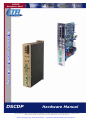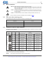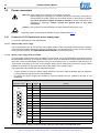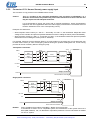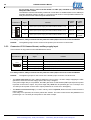
1
Artisan Technology Group is your source for quality
new and certified-used/pre-owned equipment
• FAST SHIPPING AND
DELIVERY
• TENS OF THOUSANDS OF
IN-STOCK ITEMS
• EQUIPMENT DEMOS
• HUNDREDS OF
MANUFACTURERS
SUPPORTED
• LEASING/MONTHLY
RENTALS
• ITAR CERTIFIED
SECURE ASSET SOLUTIONS
SERVICE CENTER REPAIRS
Experienced engineers and technicians on staff
at our full-service, in-house repair center
WE BUY USED EQUIPMENT
Sell your excess, underutilized, and idle used equipment
We also offer credit for buy-backs and trade-ins
www.artisantg.com/WeBuyEquipment
InstraView REMOTE INSPECTION
LOOKING FOR MORE INFORMATION?
Visit us on the web at www.artisantg.com for more
information on price quotations, drivers, technical
specifications, manuals, and documentation
SM
Remotely inspect equipment before purchasing with
our interactive website at www.instraview.com
Contact us: (888) 88-SOURCE | [email protected] | www.artisantg.com
Two axes position controller
DSCDPHardware-VerG
DSCDP
Hardware Manual
Copyright ETEL SA. All rights reserved. Reproduction, adaptation or translation of this document is prohibited without prior written permission.
ETEL SA retains the right to make any change to these specifications at any time, without notice.
Artisan Technology Group - Quality Instrumentation ... Guaranteed | (888) 88-SOURCE | www.artisantg.com
THIS PAGE IS INTENTIONALLY LEFT BLANK
Artisan Technology Group - Quality Instrumentation ... Guaranteed | (888) 88-SOURCE | www.artisantg.com
DSCDP Hardware Manual
3
Table of contents
1.
2.
3.
Introduction . . . . . . . . . . . . . . . . . . . . . . . . . . . . . . . . . . . . . . . . . . . . . .
6
1.1 Safety . . . . . . . . . . . . . . . . . . . . . . . . . . . . . . . . . . . . . . . . . . . . . . . . . . . . . . . . . .
6
1.2 DSCDP presentation . . . . . . . . . . . . . . . . . . . . . . . . . . . . . . . . . . . . . . . . . . . . . .
7
1.2.1
Working principle . . . . . . . . . . . . . . . . . . . . . . . . . . . . . . . . . . . . . . . . . . . . . . . . . . . . . . . . .
7
1.2.2
Applications . . . . . . . . . . . . . . . . . . . . . . . . . . . . . . . . . . . . . . . . . . . . . . . . . . . . . . . . . . . . .
7
1.2.3
General operating conditions . . . . . . . . . . . . . . . . . . . . . . . . . . . . . . . . . . . . . . . . . . . . . . .
7
1.2.4
Transport and storage conditions . . . . . . . . . . . . . . . . . . . . . . . . . . . . . . . . . . . . . . . . . . .
7
1.2.5
Interfaces possibilities . . . . . . . . . . . . . . . . . . . . . . . . . . . . . . . . . . . . . . . . . . . . . . . . . . . . .
7
Models characteristics . . . . . . . . . . . . . . . . . . . . . . . . . . . . . . . . . . . . .
10
2.1 Rack format . . . . . . . . . . . . . . . . . . . . . . . . . . . . . . . . . . . . . . . . . . . . . . . . . . . . .
10
2.1.1
Outline and dimensions . . . . . . . . . . . . . . . . . . . . . . . . . . . . . . . . . . . . . . . . . . . . . . . . . . . .
10
2.1.2
Block schematics . . . . . . . . . . . . . . . . . . . . . . . . . . . . . . . . . . . . . . . . . . . . . . . . . . . . . . . . .
11
2.1.3
Ratings . . . . . . . . . . . . . . . . . . . . . . . . . . . . . . . . . . . . . . . . . . . . . . . . . . . . . . . . . . . . . . . . .
12
2.1.4
Mounting systems – Installation requirements . . . . . . . . . . . . . . . . . . . . . . . . . . . . . . . . .
14
2.2 Housed format with power supply . . . . . . . . . . . . . . . . . . . . . . . . . . . . . . . . . .
16
2.2.1
Outline and dimensions . . . . . . . . . . . . . . . . . . . . . . . . . . . . . . . . . . . . . . . . . . . . . . . . . . . .
16
2.2.2
Block schematics . . . . . . . . . . . . . . . . . . . . . . . . . . . . . . . . . . . . . . . . . . . . . . . . . . . . . . . . .
17
2.2.3
Ratings . . . . . . . . . . . . . . . . . . . . . . . . . . . . . . . . . . . . . . . . . . . . . . . . . . . . . . . . . . . . . . . . .
18
2.2.4
Mounting systems – Installation requirements . . . . . . . . . . . . . . . . . . . . . . . . . . . . . . . . .
19
2.3 Ordering information . . . . . . . . . . . . . . . . . . . . . . . . . . . . . . . . . . . . . . . . . . . . .
21
Electrical interface . . . . . . . . . . . . . . . . . . . . . . . . . . . . . . . . . . . . . . . .
22
3.1 Encoder connectors . . . . . . . . . . . . . . . . . . . . . . . . . . . . . . . . . . . . . . . . . . . . . .
23
3.1.1
Connectors JC5 and JC6: Position encoders . . . . . . . . . . . . . . . . . . . . . . . . . . . . . . . . . .
23
3.2 Inputs / outputs connectors . . . . . . . . . . . . . . . . . . . . . . . . . . . . . . . . . . . . . . . .
27
3.2.1
Connectors JC9 and JC10: Customer inputs / outputs . . . . . . . . . . . . . . . . . . . . . . . . . .
27
3.3 Communication connectors . . . . . . . . . . . . . . . . . . . . . . . . . . . . . . . . . . . . . . .
30
3.3.1
Connector JC1: Turbo-ETEL-Bus input . . . . . . . . . . . . . . . . . . . . . . . . . . . . . . . . . . . . . . .
31
3.3.2
Connector JC2: Turbo-ETEL-Bus output . . . . . . . . . . . . . . . . . . . . . . . . . . . . . . . . . . . . . .
31
3.3.3
Connector JC3: ETEL-Bus-Lite2 serial communication . . . . . . . . . . . . . . . . . . . . . . . . . .
31
3.3.4
Connector JC4: Download key . . . . . . . . . . . . . . . . . . . . . . . . . . . . . . . . . . . . . . . . . . . . . .
32
3.4 Motor connectors . . . . . . . . . . . . . . . . . . . . . . . . . . . . . . . . . . . . . . . . . . . . . . . .
33
3.4.1
ETEL motor cables numbering system . . . . . . . . . . . . . . . . . . . . . . . . . . . . . . . . . . . . . . .
33
3.4.2
Connector JC7 and JC11: Motor connection . . . . . . . . . . . . . . . . . . . . . . . . . . . . . . . . . . .
33
3.5 Power connectors . . . . . . . . . . . . . . . . . . . . . . . . . . . . . . . . . . . . . . . . . . . . . . . .
34
3.5.1
Connector JC15: Rack format, power supply input . . . . . . . . . . . . . . . . . . . . . . . . . . . . .
34
3.5.2
Connector JC13: Housed format, power supply input . . . . . . . . . . . . . . . . . . . . . . . . . . .
35
3.5.3
Connector JC12: Housed format, auxiliary supply input . . . . . . . . . . . . . . . . . . . . . . . . .
36
ETEL Doc. - Hardware Manual # DSCDP / Ver G / 6/1/11
Artisan Technology Group - Quality Instrumentation ... Guaranteed | (888) 88-SOURCE | www.artisantg.com
4
DSCDP Hardware Manual
3.5.4
Connector JC14: Housed format, brake resistor . . . . . . . . . . . . . . . . . . . . . . . . . . . . . . .
37
3.6 Optional boards connector . . . . . . . . . . . . . . . . . . . . . . . . . . . . . . . . . . . . . . .
37
3.6.1
Connector JC8: Depends on the type of board . . . . . . . . . . . . . . . . . . . . . . . . . . . . . . . .
37
3.7 Cables . . . . . . . . . . . . . . . . . . . . . . . . . . . . . . . . . . . . . . . . . . . . . . . . . . . . . . . .
38
3.7.1
4.
Manufacturing . . . . . . . . . . . . . . . . . . . . . . . . . . . . . . . . . . . . . . . . . . . . . . . . . . . . . . . . . . .
38
3.8 Axis number selection . . . . . . . . . . . . . . . . . . . . . . . . . . . . . . . . . . . . . . . . . . .
39
3.9 LEDs meaning . . . . . . . . . . . . . . . . . . . . . . . . . . . . . . . . . . . . . . . . . . . . . . . . . .
40
Service and support . . . . . . . . . . . . . . . . . . . . . . . . . . . . . . . . . . . . . . .
41
ETEL Doc. - Hardware Manual # DSCDP / Ver G / 6/1/11
Artisan Technology Group - Quality Instrumentation ... Guaranteed | (888) 88-SOURCE | www.artisantg.com
DSCDP Hardware Manual
5
Record of revisions concerning the DSCDP manual:
Document revisions
Issue (x)
Date
Modified
Ver A
05.06.02
First version
Ver B
24.09.03
Updated version
- New housed format (see §2.2 and §3.5)
- Brake resistor as well as power stage and short-circuit relays on housed model (see §3.5.2,
§3.5.3 and §3.5.4)
- New signals on JC4 connector (§3.3.4)
- Additional safety precautions in accordance with the UL and CE standards
Ver C
19.12.03
Updated version
- Housed format is UL certified
Ver D
31.03.04
Updated version
- Housed format dimensions modified (see §2.2.1)
Ver E
01.11.04
Updated version
-Digital Hall effect sensor implemented (see §3.2.1.1)
Ver F
19.12.05
Updated version
- Additional detailed descriptions
Ver G
06.01.11
Updated version:
- New UL certification laboratory (TUV)
Documentation concerning the DSCDP:
•
DSCDP Hardware Manual
(Specifications & electrical interfaces)
# DSCDP 904 G
•
Operation & Software Manual
(DSCDP's setup, use & programming)
# DSC2P 903 x
•
DSO-PWS User's Manual
(Power module installation and specifications)
# DSOPWS 902 x
•
DSO-RAC2 Hardware Manual
(DSO-RAC2 principle)
# DSORAC2 904 x
•
EBL2 Communication Manual
(EBL2 principle, messages mapping)
# EBL2 908 x
The DSCDP position controllers have been successfully tested and evaluated to
meet the UL 508C for US market and CSA-C22.2 N°14-05 for canadian market.
This standard describes the fulfillment by design of minimum requirements for
electrically operated power conversion equipment which is intended to eliminate the
risk of fire, electrical shock, or injury to persons being caused by such equipment.
Remark:
By default, the DSCDP is delivered without UL recognition.
ETEL Doc.- Hardware Manual # DSCDP / Ver G / 6/1/11
Artisan Technology Group - Quality Instrumentation ... Guaranteed | (888) 88-SOURCE | www.artisantg.com
6
1.
DSCDP Hardware Manual
Introduction
This document concerns a two axes digital position controller of ETEL's DSCxx family: the DSC Dual position
controller or DSCDP also called 'controller' in this document.
The purpose of this manual is to give details regarding the specifications, installation, interfacing and hardware
items. All details for proper connections (power supply, motor, encoder connection, etc...) are provided herein.
Detailed information concerning the programming of the controller is provided in the corresponding 'Operation
& Software Manual'.
The information given in this manual is valid for type # D S C D P x x x - x x x E and later.
Remark:
1.1
The updates between two successive versions are highlighted with a modification stroke in the
margin of the manual.
Safety
Please, read all the safety precautions listed in this manual before handling the
DSCDP:
•
Never use the DSCDP for purposes other than those described in this manual.
•
A competent and trained technician must install and operate the DSCDP, in accordance with all specific
regulations of the respective country concerning both safety and EMC aspects.
•
Troubleshooting and servicing are permitted only by ETEL's technicians and agreed distributors.
•
Operating the DSCDP will make the motor move. Keep away from all moving parts to avoid
injuries!
•
The safety symbols placed on the DSCDP or written in the manuals must be respected.
•
If the DSCDP is integrated into a machine, the manufacturer of this machine must establish that it fulfils the
89/336/EEC directive on EMC before operating the controller.
Warning:Signals a danger of electrical shock to the operator.
Can be fatal for a person.
Caution: Signals a danger for the DSCDP. Can be destructive for the material.
A danger for the operator can result from this.
Caution: Indicates electrostatic discharges (ESD), dangerous for the DSCDP.
The components must be handled in an ESD protected environment only.
Remark:
The DSCDP associated to its motor connector complies with the 89/336/EEC directive on EMC
and the 73/23/EEC low voltage directive.
ETEL Doc. - Hardware Manual # DSCDP / Ver G / 6/1/11
Artisan Technology Group - Quality Instrumentation ... Guaranteed | (888) 88-SOURCE | www.artisantg.com
DSCDP Hardware Manual
1.2
DSCDP presentation
1.2.1
Working principle
7
The DSCDP is a digital position controller. It has been designed for direct drive applications. Its power bridge
PWM switching is determined by the motor position encoder. The DSCDP includes on a single board, the
control circuits, the power bridge and all the necessary interfaces for the communication, the encoders and the
inputs/outputs for two motors. The housed model includes also a power supply on the same board, inside the
same housing.
1.2.2
Applications
The DSCDP can drive two, single-phase, two-phase or/and three-phase motors. You can obtain brushless
torque and linear motors from ETEL, as well as moving coils and moving magnets. The DSCDP can drive these
motors and also brushless motors, DC motors, steppers (only if three-phase motors are star-connected). They
must also be implemented with analog (incremental or absolute (EnDat 2.1)) or TTL encoders available on the
market. Digital Hall effect sensor can also be connected to the controller (with firmware from version 1.12A). It
is also possible to drive stepper motors in open loop (no need of encoder in this case) with firmware from
version 1.14A.
1.2.3
General operating conditions
The DSCDP is designed to operate in a non-aggressive and clean environment, with a humidity rate ranging
between 10% and 85%, an altitude < 2000m (6562 ft), and a temperature ranging between +15°C (59°F) and
+40°C (104°F) for the rack format or +30°C (86°F) for the housed format. The DSCDP must be connected to
an electrical network of overvoltage category 2 (refer to EN 50178 and UL 840 standards for more information)
and is suitable for use on a circuit capable of delivering not more than 5000 Arms, symmetrical amperes, 400
volts maximum. The electronics must be in an enclosure respecting a pollution degree of 2 (refer to UL 508C
and EN 50178 standards for more information). The DSCDP is not designed or intended for use in the on-line
control of air traffic, aircraft navigation and communications as well as critical components in life support
systems or in the design, construction, operation and maintenance of any nuclear facility.
1.2.4
Transport and storage conditions
During the transport and the storage, the controller must remain inside its original packaging. The transport
conditions must respect the class 2K3 of the IEC 60721-3-2 standard (temperature between -25°C and +70°C,
and humidity < 95% without condensation) and the storage conditions must respect the class 1K2 of the IEC
60721-3-1 standard (temperature between +5°C and +45°C, and humidity between 5 and 85% without
condensation).
1.2.5
Interfaces possibilities
Motor and its position encoder
To control the position (in closed loop) of a rotary and/or linear motor, the DSCDP needs a signal coming from
an analog (incremental or absolute (EnDat 2.1)) or a TTL encoder linked to this or these motor(s). It is also
possible to drive stepper motors in open loop (no need of encoder in this case).
Communication
The user can set the DSCDP with a PC (Win 9x/2000/NT/XP) using the ETEL Tools (ETT) software through
the ETEL-Bus-Lite2 (RS232 / RS422) communication port. Refer to the 'EBL2 Communication Manual' for
more information.
The DSCDP also includes ETEL's Turbo-ETEL-Bus (TEB) which is a high speed field bus based on an Ethernet
100 Mbps chip. It includes all features to interpolate complex movements with several synchronized DSCDPs,
if ETEL's DSMAX motion controller is installed in a PC and linked to the TEB. If ETEL Tools is installed on the
same PC than the DSMAX (or DSTEB) board, all the DSCDPs can be set through the TEB. The user can 'daisy
chain' up to 31 nodes on the TEB (15 DSCDPs (30 axes) and one DSMAX (or DSTEB) board).
Caution:
The TEB is not compatible with Ethernet boards available on the market. Therefore, do not
connect the TEB on the Ethernet port of your PC.
Inputs / outputs
The customer's inputs / outputs are digital signals coming from a CNC machine-tool, a PLC or a joystick for
example (refer to the connection diagram next page).
The electrical interface details are given in §3.
ETEL Doc.- Hardware Manual # DSCDP / Ver G / 6/1/11
Artisan Technology Group - Quality Instrumentation ... Guaranteed | (888) 88-SOURCE | www.artisantg.com
8
DSCDP Hardware Manual
Connection diagram:
Rack format
ETEL's DSCDP
15 slaves (max.)
+ DSMAX (or DSTEB)
Optional board
Communication with PC/CNC/
PLC (setup with ETT or ComET
software or 'host' commands)
Customers inputs / outputs
(CNC, PLC or joystick ...)
Rotary / linear incremental or
absolute (EnDat 2.1) analog
/ TTL encoder for motor M1
Rotary or linear motor for M1
Rotary / linear incremental or
absolute (EnDat 2.1) analog
/ TTL encoder for motor M2
Rotary or linear motor for M2
ETEL Doc. - Hardware Manual # DSCDP / Ver G / 6/1/11
Artisan Technology Group - Quality Instrumentation ... Guaranteed | (888) 88-SOURCE | www.artisantg.com
DSCDP Hardware Manual
9
Housed format
ETEL's DSCDP
15 slaves (max.)
+ DSMAX (or DSTEB)
Optional board
Communication with PC/CNC/
PLC (setup with ETT or ComET
software or 'host' commands)
Customers inputs / outputs
(CNC, PLC or joystick ...)
Rotary / linear incremental or
absolute (EnDat 2.1) analog
/ TTL encoder for motor M1
Rotary or linear motor for M1
Rotary / linear incremental or
absolute (EnDat 2.1) analog
/ TTL encoder for motor M2
Rotary or linear motor for M2
Auxiliary
power supply
Mains
Braking resistor
ETEL Doc.- Hardware Manual # DSCDP / Ver G / 6/1/11
Artisan Technology Group - Quality Instrumentation ... Guaranteed | (888) 88-SOURCE | www.artisantg.com
10
2.
DSCDP Hardware Manual
Models characteristics
Three models of DSCDP are available, according to the needs:
1. Rack format with plate heat sink (refer to §2.1)
2. Rack format with extruded heat sink (refer to §2.1)
These 2 models are dedicated to be mounted inside a standard 6U rack case. They do not include any power
supply board and need to be powered through their DC power connector (JC15) by an external power supply
(the ETEL DSO-PWS power module, e.g.), ideally installed inside the rack case.
3. Housed format with power supply (refer to §2.2)
This controller is a 'stand alone' controller. It includes a complete controller with its power supply inside the
same housing. The main difference between the rack formats and the housed format concerns the power
supply connectors.
2.1
Rack format
There are two different sizes of DSCDP rack format: the DSCDPxx1–xxx (10F wide) and the DSCDPxx2–xxx
(14F wide).
Outline and dimensions
Refer to the following chapters for more details about the connectors:
JC1 (see §3.3.1)
JC2 (see §3.3.2)
JC3 (see §3.3.3)
JC4 (see §3.3.4)
JC5 (see §3.1.1)
JC6 (see §3.1.1)
JC7 (see §3.4.2)
JC8 (see §3.6.1)
JC9 (see §3.2.1)
JC10 (see §3.2.1)
JC11 (see §3.4.2)
JC15 (see §3.5.1)
164.00
261.80
164.00
261.80
2.1.1
Standard 6U 10F
Standard 6U 14F
Unit: [mm]
Unit: [mm]
Weight: 1.1 Kg
50.60
Weight: 2.0 Kg
70.80
ETEL Doc. - Hardware Manual # DSCDP / Ver G / 6/1/11
Artisan Technology Group - Quality Instrumentation ... Guaranteed | (888) 88-SOURCE | www.artisantg.com
DSCDP Hardware Manual
2.1.2
11
Block schematics
SERVO BOARD
JC11
Current
measure.
PH1 & 3
PE
PH3
O
U
T
P
U
T
PH2
M2
PH1
M1
PE
DSO-HIO
IGBT drive
unit
IGBT power bridge
M2
PH3
PH2
PH1 JC7
M
O
T
O
R
In the DSCDP rack formats, all parts are on a single board: the servo board. They need to be powered by an
external power supply. The power supply developed by ETEL (refer to the 'DSO-PWS User's Manual' for
more information) is designed to fit most applications. If you use another power supply, it must meet all the
specifications written on the next page. On the servo board, the power part and the control part are galvanically
separated. The inputs and outputs are insulated from the control part by opto-couplers.
Current
measure.
PH1 & 3
PROFIBUS
MACRO bus
Thermostat
galvanic
insulation
(CONTROL)
ETEL-Bus-Lite2
IN / OUT
TEB
/ OUT
JC6
JC10
JC9
JC8
Fuse
Fuse
JC5
DC
Analog(*) / TTL
encoder input M1
M
O
V
GNDaux
+Vaux Fuse
Analog(*) / TTL
encoder input M2
Fuse
DC
DC
DC
Digital control
Digital
inputs M1
Fuse
Fuse
(POWER)
galvanic
insulation
Digital
inputs M2
IN
S
U
P
P
L
Y
P
O
W
E
R
E
X
T
E
R
N
A
L
I
N
P
U
T
GNDpwr
M
O
V
+Vpwr
P
O
W
E
R
JC15
Remark:
Digital
outputs M2
Digital
outputs M1
Overcurrent
detection
Over / under
voltage
DIP switch
AXIS #
Optional
board
JC1 to 3
IGBT drive
unit
IGBT power bridge
M1
CAN bus
M1 and M2 represent the motor 1 and the motor 2 respectively.
(*): it is possible to plug an EnDat 2.1 encoder (D-Sub 15 pins high density connector) but only
with the DSCDP3xx-xxx version.
Caution: The GND is internally connected to the DSCDP front panel which is connected to the
ground (PE).
The power GND is not connected to the ground (PE).
ETEL Doc.- Hardware Manual # DSCDP / Ver G / 6/1/11
Artisan Technology Group - Quality Instrumentation ... Guaranteed | (888) 88-SOURCE | www.artisantg.com
12
2.1.3
DSCDP Hardware Manual
Ratings
To meet the specifications listed below, it is recommended to use an ETEL power supply (DSO-PWS). There
are two different types of 10F wide rack formats (the DSCDPx21-xxx and the DSCDPx31-xxx) and one type of
14F wide rack format (the DSCDPx32-xxx).
All the specifications are given for an ambient temperature ranging from +15°C (59°F) to +40°C (104°F)
and with an air flow of 2 m/s (400 LFM) inside the rack case:
Remark:
The values given in the following table are valid for each motor.
DSCDP POWER FEATURES for RACK FORMAT
Characteristics
DSCDPx21-xxx
Voltage (up to)
Output to the motor
(per motor)
Power supply input
Auxiliary supply input
for DSCDPxxx-x1x
Auxiliary supply input
for DSCDPxxx-x2x
DSCDPx31-xxx
DSCDPx32-xxx
400 VDC
Current range on product label
3 Arms / 7.5 Arms (1s)
3.5 Arms / 15 Arms (1s)
7 Arms / 15 Arms (1s)
Three-phase motor
Max. full load current
PWM at 18 kHz
4.9(1) A
(3.5 Arms)
4.9(1) A
(3.5 Arms)
11(1) A
(7.5 Arms)
Three-phase motor
Max. overload current
during 2 seconds
PWM at 18 kHz
11 A
(7.5 Arms)
21 A
(14.9 Arms)
21A
(14.9 Arms)
Two-phase motor
Max. full load current
PWM at 18 kHz
4.9(1) A
(3.5 Arms)
4.9(1) A
(3.5 Arms)
11(1) A
(7.5 Arms)
Two-phase motor
Max. overload current
during 2 seconds
PWM at 18 kHz
9A
(6.4 Arms)
19 A
(13.5 Arms)
19A
(13.5 Arms)
One-phase motor
Max. full load current
PWM at 18 kHz
4.9(1) A
(3.5 Arms)
4.9(1) A
(3.5 Arms)
11(1) A
(7.5 Arms)
One-phase motor
Max. overload current
during 2 seconds
PWM at 18 kHz
11 A
(7.5 Arms)
21 A
(14.9 Arms)
21A
(14.9 Arms)
Current ripple frequency
36 kHz
DC voltage
24 - 400 VDC
DC voltage
120 - 340 VDC
Max. current at 120 VDC
200 mA(2)
Max. current at 340 VDC
70 mA(2)
DC voltage
24 - 55 VDC
Max. current at 24 VDC
1 A(2)
Max. current at 55 VDC
500 mA(2)
Maximum current measurable by the controller
12.5 A
25 A
25 A
(1):
Continuous current can be reached only with forced air cooling (external fan necessary: refer to §2.1.4).
With optional board mounted on the DSCDP, no external device connected to the I/O. The current can
change depending on the type(s) of encoder(s) used.
Note: for DSCDPxxx-x2x, the DC current is equal to 450 mA at 48 VDC.
(2):
Remark:
With PWM at 18 kHz, the current ripple in the motor is at 36 kHz.
With two-phase motor, the current in 'motor phase 1- / 2-' (pin 3 of JC7 and JC11 connectors) is
equal to (√2 x motor phase 1+) or (√2 x motor phase 2+). Be careful to use the suitable cable
diameter.
ETEL Doc. - Hardware Manual # DSCDP / Ver G / 6/1/11
Artisan Technology Group - Quality Instrumentation ... Guaranteed | (888) 88-SOURCE | www.artisantg.com
DSCDP Hardware Manual
13
DSCDP CONTROL FEATURES for RACK FORMAT
General
Standard
interfaces
Position
encoders
interfaces
Motion profile and command
management sampling time
500 µs
Current loop sampling time
55.56 µs
Position loop sampling time
55.56 µs
Motion profiles
Trapezoidal / S-curve / sine / look-up table / ...
interpolated (DSMAX)
32 bits floating point DSP
Dual SHARC Digital Signal Processor
ETEL-BUS-LITE 2 host (PC) communication
RS232 or RS422 / 115'200 bps
Turbo-ETEL-Bus multi-axis communication
100 Mbps (based on Ethernet components)
CAN interface option
with DSO-CAN board
PROFIBUS interface option
with DSO-PRO board
MACROBUS interface option
with DSO-MAC board
Analog 1Vptp
TTL encoder possible
EnDat 2.1 compatible input (EDT + ECL)
RS485 (from rack format version DSCDP3xx-xxxE)
Encoder limit switch (EHO + ELS)
TTL signal (from rack format version DSCDP3xx-xxxE)
Digital input, insulated
4 per motor
(+ 8 with DSO-HIO optional board but shared between both motors)
Digital output, insulated
2 per motor
(+ 8 with DSO-HIO optional board but shared between both motors)
Analog input
0 (+ 4 depending on the DSO-HIO optional board version but
shared between both motors)
Analog output
0 (+ 4 depending on the DSO-HIO optional board version but
shared between both motors)
ETEL Tools software for setting / monitoring
Windows 9x / 2000 / NT / XP
DLL files (C / C++ / VB / LV)
Windows 9x / 2000 / NT / XP / QNX4 / QNX6
User's programmable sequence
4096 lines per axis
Firmware update
RS232, Turbo-ETEL-Bus
User's
inputs / outputs
Software /
programmability
Max. 400kHz in. / up to 2'048 (x4) interpol. factor (per motor)
Max. 400KHz (per motor)
ETEL Doc.- Hardware Manual # DSCDP / Ver G / 6/1/11
Artisan Technology Group - Quality Instrumentation ... Guaranteed | (888) 88-SOURCE | www.artisantg.com
14
Mounting systems – Installation requirements
The DSCDP rack formats are dedicated to be mounted inside a rack case system.
Warning: The rack case with the controllers and the power supply has the following electrical
safety degree: IP 20 (according to EN 60529 standard). To respect this degree, each
empty slot (if a controller is not present in the rack case) must be closed by a front
panel. The rack case must be in an enclosure respecting a pollution degree of 2 (refer
to UL 508C and EN 50178 standards for more information).
The rack formats are mounted vertically inside a rack case. Here is an example
483.00 (19'')
426.72 (84F)
190.50
265.90
261.80 (6U)
2.1.4
DSCDP Hardware Manual
465.10
Rack case depth: 240 (without the depth of the handle)
Unit: [mm]
In the solution outlined above, seven DSCDPxx1-xxx are powered by a DSO-PWS (ETEL's power supply).
The rack case systems should be protected against any splashes of liquid and any contacts with smoke and
dust. It must be installed inside a closed cabinet and screwed on a metallic plate, connected to the ground,
where no vibration will occur.
Fresh air is necessary to cool the controllers inside the rack case (the flow depends on the user application). It
is recommended to install fans in the cabinet to guarantee an air flow (the fan power depends on the user
application). Caution: some fans may perturb the current measurement of the controller if they are too
close to the rack case. If this problem occurs, use another type of fan or increase the distance between
the fan and the rack case while ensuring the air flow mentioned hereafter. The air flow inside ETEL's rack
cases with fans is equal to minimum 2 m/s (400 LFM) (the fans, used with the rack case, have an air flow of
94.2 CFM). Refer to the 'DSO-RAC2 Hardware Manual' for more information about the rack case.
ETEL Doc. - Hardware Manual # DSCDP / Ver G / 6/1/11
Artisan Technology Group - Quality Instrumentation ... Guaranteed | (888) 88-SOURCE | www.artisantg.com
DSCDP Hardware Manual
15
This drawing shows a rack case with rack formats, inside a cabinet:
Dust filter
The following distances are recommended: A = 100 [mm] (drawing out of scale).
ETEL Doc.- Hardware Manual # DSCDP / Ver G / 6/1/11
Artisan Technology Group - Quality Instrumentation ... Guaranteed | (888) 88-SOURCE | www.artisantg.com
16
2.2
DSCDP Hardware Manual
Housed format with power supply
There is one size of DSCDP housed format: the DSCDPxx4-xxx (72 x 224 x 376 mm).
Outline and dimensions
Refer to the following chapters for details about the connectors:
JC5 (see §3.1.1)
JC6 (see §3.1.1)
JC7 (see §3.4.2)
JC8 (see §3.6.1)
JC9 (see §3.2.1)
JC10 (see §3.2.1)
JC11 (see §3.4.2)
JC12 (see §3.5.3)
JC13 (see §3.5.2)
JC14 (see §3.5.4)
46
13
6
JC1 (see §3.3.1)
JC2 (see §3.3.2)
JC3 (see §3.3.3)
JC4 (see §3.3.4)
224
363.5
14
∅ 6.5
6.5
6.5
348
2.2.1
Unit: [mm]
weight: 5 Kg
72
Remark:
2 mm must be added to the above-mentioned width of the controller to take the screw heads into
account.
ETEL Doc. - Hardware Manual # DSCDP / Ver G / 6/1/11
Artisan Technology Group - Quality Instrumentation ... Guaranteed | (888) 88-SOURCE | www.artisantg.com
DSCDP Hardware Manual
2.2.2
17
Block schematics
Current
measure.
PH1 & 3
IGBT drive
unit
IGBT power bridge
M2
SERVO BOARD
PE
JC11
PH3
O
U
M2 T
P
U
T
PH2
PH1
PE
PH3
PH2
DSO-HIO
Current
measure.
PH1 & 3
PROFIBUS
MACRO bus
JC8
JC10
Digital control
Fuse
Fuse
Overcurrent
detection
ETEL-Bus-Lite2
IN / OUT
TEB
/ OUT
JC6
JC5
JC1 to 3
Analog(*) / TTL
encoder input M1
Fuse
Fuse
DC
DC
galvanic
insulation
(CONTROL)
Fuse
M
O
V
DC
(POWER)
galvanic
insulation
Analog(*) / TTL
encoder input M2
IN
JC12
A
U POWER
X STAGE
RELAY I
N
+Vaux
P
U GNDaux
T
+
PE
P JC13
L1
O
W
E
R
L2
I
N
P
U
L3
T
M
O
V
Filter
Digital
inputs M2
Digital
inputs M1
DC
Inrush
limit
Fuse
Digital
outputs M2
Digital
outputs M1
Fan
Over
voltage
JC14
Ext.
brake
resistor
≥40Ω
Over / under
voltage
Fuse
DIP switch
AXIS #
Optional
board
JC9
IGBT drive
unit
IGBT power bridge
M1
CAN bus
Thermostat
PH1
GNDaux
JC7
+24 VDC
Optional shortcircuit relay
M
O
M1 T
O
R
The housed format contains two boards: the servo board and the power supply board. On the servo board, the
power part and the control part are galvanically separated. The inputs and outputs are insulated from the
control part by opto-couplers.
Caution: The GND is internally connected to the DSCDP front panel which is connected to the
ground (PE).
The power GND is not connected to the ground (PE).
ETEL Doc.- Hardware Manual # DSCDP / Ver G / 6/1/11
Artisan Technology Group - Quality Instrumentation ... Guaranteed | (888) 88-SOURCE | www.artisantg.com
18
2.2.3
DSCDP Hardware Manual
Ratings
There are two different types of DSCDP housed formats: the DSCDPx24-xxx and the DSC2Px34-xxx.
All the specifications are given for an ambient temperature ranging from +15°C (59°F) to +30°C (86°F):
Remark:
The values given in the following table are valid for each motor.
DSCDP POWER FEATURES for HOUSED FORMAT
Characteristics
DSCDPx24-xxx
Voltage (up to)
Output to the motor
(per motor)
Power supply input
DSCDPx34-xxx
400 VDC
Current range on product label
3 Arms / 7.5 Arms (1s)
7 Arms / 15 Arms (1s)
Three-phase motor
Max. full load current
PWM at 18 kHz
4.9 A
(3.5 Arms)
10 A
(7 Arms)
Three-phase motor
Max. overload current during 2 seconds
PWM at 18 kHz
11 A
(7.7 Arms)
21 A
(14.9 Arms)
Two-phase motor
Max. full load current
PWM at 18 kHz
4.9 A
(3.5 Arms)
9A
(6.3 Arms)
Two-phase motor
Max. overload current during 2 seconds
PWM at 18 kHz
9A
(6.4 Arms)
18 A
(12.7 Arms)
One-phase motor
Max. full load current
PWM at 18 kHz
4.9 A
(3.5 Arms)
8A
(5.6 Arms)
One-phase motor
Max. overload current during 2 seconds
PWM at 18 kHz
11 A
(7.7 Arms)
16 A
(11.3 arms)
Current ripple frequency
36 kHz
AC voltage (single or three-phase)
84 - 280 VAC
Max. AC current at 1x or 3x 84 - 280 VAC
1x or 3x 6 A
Max. inrush current per phase at 280 VAC
15 Apeak
DC voltage
24 VDC
Max. current at 24 VDC
1 A(1)
Auxiliary supply input
Maximum current measurable by the controller
12.5 A
25 A
(1): With optional board mounted on the DSCDP, no external device connected to the I/O. The current can
change depending on the type(s) of encoder(s) used. A current equal to about twice the above-mentioned
value can be necessary to switch on the controller (because of the trigger pulse).
Remark:
With PWM at 18 kHz, the current ripple in the motor is at 36 kHz.
With two-phase motor, the current in 'motor phase 1- / 2-' (pin 3 of JC7 and JC11 connectors) is
equal to (√2 x motor phase 1+) or (√2 x motor phase 2+). Be careful to use the suitable cable
diameter.
For an ambient temperature exceeding +30°C, a derating of 0.3 A per degree must be applied on
the above-mentioned current values
The values given in the above-mentioned table are given for a sinusoidal output current with a
frequency higher than 0.5 Hz. The losses induced by a AC current are shared between the
transistors. A DC current heat up only some of the IGBTs and can induce their breakdown after
10 minutes if the current is near the maximum full load.
ETEL Doc. - Hardware Manual # DSCDP / Ver G / 6/1/11
Artisan Technology Group - Quality Instrumentation ... Guaranteed | (888) 88-SOURCE | www.artisantg.com
DSCDP Hardware Manual
19
DSCDP CONTROL FEATURES for HOUSED FORMAT
General
Standard
interfaces
Motion profile and command
management sampling time
500 µs
Digital current loop sampling time
55.56 µs
Position loop sampling time
55.56 µs
Motion profiles
Trapezoidal / S-curve / sine / look-up table / interpolated (DSMAX)
32 bits floating point DSP
Dual SHARC Digital Signal Processor
Power stage relay
Relay cutting the + 15 VDC voltage of the power part
Brake resistor
External > 40Ω with thermal switch protection
ETEL-BUS-LITE 2 host (PC) communication
RS232 or RS422 / 115'200 bps
Turbo-ETEL-Bus multi-axis communication
100 Mbps (based on Ethernet components)
CAN interface option
with DSO-CAN board
PROFIBUS interface option
with DSO-PRO board
MACROBUS interface option
with DSO-MAC board
Analog 1Vptp
TTL encoder possible
Position
encoders
interfaces
EnDat 2.1 compatible input (EDT + ECL)
RS485
Encoder limit switch (EHO + ELS)
TTL signal
Digital input, insulated
4 per motor
(+ 8 with DSO-HIO optional board but shared between both motors)
Digital output, insulated
2 per motor
(+ 8 with DSO-HIO optional board but shared between both motors)
Analog input
0 (+ 4 depending on the DSO-HIO optional board version but
shared between both motors)
Analog output
0 (+ 4 depending on the DSO-HIO optional board version but
shared between both motors)
ETEL Tools software for setting / monitoring
Windows 9x / 2000 / NT / XP
DLL files (C / C++ / VB)
Windows 9x / 2000 / NT / XP / QNX4 / QNX6
User's programmable sequence
4096 lines per axis
Firmware update
RS232 / Turbo-ETEL-Bus
Motor's short-circuit relay
Relay short-circuiting the motor's phases
User's
inputs / outputs
Software /
programmability
Option
2.2.4
Max. 400kHz in. / Up to 2'048 (x4) interpolation factor (per motor)
Max. 400kHz (per motor)
Mounting systems – Installation requirements
Warning: The housed format has the following electrical safety degree: IP 20 (according to EN
60529 standard).
The housed format must be installed in an enclosure respecting a pollution degree of
2 (refer to UL 508C and EN 50178 standards for more information).
The controllers should be protected against any splashes of liquid and any contacts with smoke and dust. They
must be installed inside a closed cabinet and screwed on a metallic plate, where no vibration will occur. The
ground of the controller(s) must be connected prior to any other connections.
A fan is already present in the housing of the housed format. Nevertheless, it is recommended to install fans
in the cabinet to guarantee an air flow (the fan power depends on the user application).
ETEL Doc.- Hardware Manual # DSCDP / Ver G / 6/1/11
Artisan Technology Group - Quality Instrumentation ... Guaranteed | (888) 88-SOURCE | www.artisantg.com
20
DSCDP Hardware Manual
Optional fans
Dust filter
The following distance is recommended: A = 100 [mm] (drawing out of scale).
ETEL Doc. - Hardware Manual # DSCDP / Ver G / 6/1/11
Artisan Technology Group - Quality Instrumentation ... Guaranteed | (888) 88-SOURCE | www.artisantg.com
DSCDP Hardware Manual
2.3
21
Ordering information
Here is the ordering information describing the meaning of each digit present on the label of the DSCDP:
D S C D P 3 2 1
-
1 1 1 X
Family product:
DSCDP: 400VDC position controller
Encoder type:
1 = Analog (1Vptp) or TTL
3 = Analog (1Vptp) or absolute (EnDat 2.1) or TTL
Power output:
2 = 3 Arms / 7.5 Arms (1s)
3 = 3.5 Arms (for 10F rack) or 7 Arms (for 14F rack or housed
format) / 15 Arms (1s)
Assembly:
1 = Rack format with plate heat sink and frontplate of 10F
(available with power output 2 and 3, with relay option 1)
2 = Rack format with extruded heat sink and frontplate of 14F
(available with power output 3 and with relay option 1)
4 = Housed format (available with power output 2 and 3, with
relay option 3 or 4, with auxiliary supply input 2 and necessarily
with encoder type 3)
Relay option:
1 = Without relay (only for rack format assembly 1 and 2)
3 = With power stage relay (only for housed format assembly 4)
4 = With motor’s short-circuit relay AND power stage relay (only
for housed format assembly 4)
Auxiliary supply input:
1 = 120 - 340VDC
2 = 24 - 55VDC (only +24VDC for housed format assembly 4)
Standard option:
1 = Not UL recognized
2 = UL recognized
By default, the DSCDP is delivered without UL recognition
Hardware version
Customer modification
000 means ’standard product’
Remark:
Not all the combinations are possible.
ETEL Doc.- Hardware Manual # DSCDP / Ver G / 6/1/11
Artisan Technology Group - Quality Instrumentation ... Guaranteed | (888) 88-SOURCE | www.artisantg.com
-
0 0 0
22
3.
DSCDP Hardware Manual
Electrical interface
This chapter describes the pin assignment for every connector. More detailed explanations for proper
connections are given in each case.
There are six groups of connectors, according to their function:
Encoders connectors (see §3.1).
Inputs / outputs connectors (see §3.2).
Communication connectors (see §3.3).
Motor connectors (see §3.4).
Power connectors (see §3.5).
Optional boards connector (see §3.6).
Warning: High voltage may be present on the power and motor connectors.
Before connecting or disconnecting a cable on one of these connectors or touching
the controller, turn off all the power supplies and wait 10 minutes to allow the
internal DC bus capacitors to discharge.
Caution: All the inputs/outputs cables must be insulated (no contact) from the power and
the mains.
The inputs and outputs must be connected to an Extra Low Voltage circuit only
(SELV).
Most inputs and outputs are not galvanically insulated from the GND.
The motor connectors must always be correctly screwed onto the DSCDP.
Caution: All the connectors must be handled in an ESD protected environment, only.
Remark:
In the next paragraphs, connectors with male pins are indicated with the • symbol (full), and
female pins are represented with the ο symbol (empty).
ETEL Doc. - Hardware Manual # DSCDP / Ver G / 6/1/11
Artisan Technology Group - Quality Instrumentation ... Guaranteed | (888) 88-SOURCE | www.artisantg.com
DSCDP Hardware Manual
3.1
Encoder connectors
3.1.1
Connectors JC5 and JC6: Position encoders
23
Caution: The encoder cable(s) must be insulated (no contact) from the power and the mains.
The inputs and outputs of this connector are not galvanically insulated from the GND.
The inputs and outputs must be connected to an Extra Low Voltage circuit only
(SELV).
Caution: The encoder connectors must be handled in an ESD protected environment, only.
Remark:
The encoder cable(s) connected to the DSCDP must be shielded (see §3.7.1).
Depending on the version of the DSCDP rack format, two types of encoder connector can be found:
• a D-Sub, 9 pins, connector on the DSCDP1xx-xxx where an incremental analog encoder 1 Vptp or a TTL
encoder can be connected.
• a D-Sub 15 pins high density connector on the DSCDP3xx-xxx and later where an incremental analog
encoder 1 Vptp, or an analog absolute encoder (EnDat 2.1) or a TTL encoder can be connected.
The DSCDP housed format includes only a D-Sub 15 pins high density encoder connector.
Remark:
3.1.1.1
JC5 is used to connect the encoder of motor 1 and JC6 for the one of motor 2.
Incremental analog encoder (1 Vptp)
The incremental analog encoder has 1Vptp signals with a load resistor R0=120Ω. It determines the motor
position thanks to two sinusoidal signals with a 90° phase-shift (sine and cosine). A third signal, the index (also
called reference mark) gives the absolute motor position:
Sine
+0.5V
Position
0V
-0.5V
Cosine
+0.5V
Position
0V
-0.5V
Index
Position
Reference mark acquisition zone
The D-Sub 9 pins connector is only available on the DSCDP1xx-xxx.
D-SUB, 9 pins, female
ANALOG ENCODER
ANALOG ENCODER
JC5 & JC6
9
6
Remark:
5
1
Pin #
Signal
Function
1
SIN -
Sine - signal input
2
GND
Encoder supply output (0V)
3
COS -
Cosine - signal input
4
GND
Encoder supply output (0V)
5
IDX -
Index - signal input
6
SIN +
Sine + signal input
7
+5VDC
Encoder supply output (protected by F3 1A)
8
COS +
Cosine + signal input
9
IDX +
Index + signal input
Interface
C
DSCDP
COS+
SIN+
IDX+
R
R0
COSSINIDX-
R
The +5VDC encoder supply output is protected by the fuse F3 (1A) on JC5 and JC6.
ETEL Doc.- Hardware Manual # DSCDP / Ver G / 6/1/11
Artisan Technology Group - Quality Instrumentation ... Guaranteed | (888) 88-SOURCE | www.artisantg.com
C
24
DSCDP Hardware Manual
The D-Sub 15 pins high-density connector is only available on the DSCDP3xx-xxx.
D-SUB, 15 pins, high density, female
ANALOG ENCODER
ANALOG ENCODER
JC5 & JC6
15
11
Remark:
5
1
Pin #
Signal
Function
1
Reserved Do not connect
2
Reserved Do not connect
3
Reserved Do not connect
4
+5VDC
5
GND
Encoder supply output (0V)
6
COS -
Cosine - signal input
7
SIN -
Sine - signal input
8
IDX -
Index - signal input
9
Interface
Encoder supply output (protected by fuse F3 of 1A)
Reserved Do not connect
10
EHO
Encoder home switch input (TTL signal)
11
ELS
Encoder limit switch input (TTL signal)
12
GND
Encoder supply output (0V)
13
COS +
Cosine + signal input
14
SIN +
Sine + signal input
15
IDX +
Index + signal input
C
DSCDP
COS +
SIN +
IDX +
R
R0
COS SIN IDX -
R
C
The +5VDC encoder supply output is protected by the fuse F3 (1A) on JC5 and JC6.
Refer to the corresponding ’Operation & Software Manual’ for more information about the use
of the EHO and ELS signals.
JC5 is used to connect the encoder of motor 1 and JC6 for the one of motor 2.
3.1.1.2
Absolute analog encoder (EnDat 2.1)
The EnDat 2.1 is an absolute encoder. It has 1Vptp signals with a load resistor R0=120Ω. Its signals are
similar to the incremental encoders (without the index), but it additionally includes a RS485 serial link (EIA
standard, EnDat 2.1 interface) for the absolute position measure: EDT (serial data) and ECL (clock). The ECL
(clock) signal is received from the DSCDP. From its first falling edge (latch signal), the absolute position will
be defined within one incremental signal period (depends on the encoder type).
The D-Sub 15 pins high-density connector is only available on the DSCDP3xx-xxx.
ETEL Doc. - Hardware Manual # DSCDP / Ver G / 6/1/11
Artisan Technology Group - Quality Instrumentation ... Guaranteed | (888) 88-SOURCE | www.artisantg.com
DSCDP Hardware Manual
25
D-SUB, 15 pins, high density, female
ANALOG
ENCODER
ANALOG ENCODER
JC5 & JC6
15
11
Remark:
5
1
Pin #
Signal
Function
1
EDT +
EnDat serial data I/O + / RS485
2
ECL +
EnDat clock output + / RS485
3
ECL -
EnDat clock output - / RS485
4
+5VDC
5
GND
Encoder supply output (0V)
6
COS -
Cosine - signal input
7
SIN -
Sine - signal input
8
Reserved
9
EDT -
Interface
Encoder supply output (protected by fuse F3 of 1A)
R
COS +
SIN +
Do not connect
COS SIN -
EnDat serial data I/O - / RS485
R0
R
10
Reserved
Do not connect
11
Reserved
Do not connect
12
GND
13
COS +
Cosine + signal input
14
SIN +
Sine + signal input
15
Reserved
C
DSCDP
C
Encoder supply output (0V)
Do not connect
The +5VDC encoder supply output is protected by the fuse F3 (1A) on JC5 and JC6.
The cable used with an absolute analog encoder (EnDat 2.1) must have power wires with a
minimum diameter to guarantee a sufficient voltage at the terminals of the encoder (refer to the
data sheet of the encoder for more information).
JC5 is used to connect the encoder of motor 1 and JC6 for the one of motor 2.
3.1.1.3
TTL encoder
Caution:
It is possible to connect a TTL encoder on this connector but the input frequency is limited
to 400KHz because the interface is an analog one.
TTL encoders measure the motor position with 2 phase-shifted TTL signals. Each change of state of one of the
signals corresponds to an increment of the motor position. A third signal (index) gives the motor absolute
position. The encoder TTL signals have to be compatible with the EIA standard RS422. These signals have
the following form:
Signal TTL1 (UA1)
Signal TTL2 (UA2)
Index TTL0 (UA0)
Reference mark acquisition zone
ETEL Doc.- Hardware Manual # DSCDP / Ver G / 6/1/11
Artisan Technology Group - Quality Instrumentation ... Guaranteed | (888) 88-SOURCE | www.artisantg.com
26
DSCDP Hardware Manual
The D-Sub 9 pins connector is only available on the DSCDP1xx-xxx.
D-SUB, 9 pins, female
ANALOG
ANALOG ENCODER
ENCODER
JC5 & JC6
9
6
Remark:
5
1
Pin #
Signal
Function
1
UA1 -
TTL 1 - signal input
2
GND
Encoder supply output (0V)
3
UA2 -
TTL 2 - signal input
4
GND
Encoder supply output (0V)
5
UA0 -
TTL 0 - signal input
Interface
C
DSCDP
UA0 +
UA1 +
UA2 +
R
R0
UA0 UA1 UA2 -
6
UA1 +
TTL 1 + signal input
7
+5VDC
Encoder supply output (protected by F3 1A)
8
UA2 +
TTL 2 + signal input
9
UA0 +
TTL 0 + signal input
C
R
The +5VDC encoder supply output is protected by the fuse F3 (1A) on JC5 and JC6.
The D-Sub 15 pins high-density connector is only available on the DSCDP3xx-xxx.
D-SUB, 15 pins, high density, female
ANALOG ENCODER
ANALOG ENCODER
JC5 & JC6
15
11
Remark:
5
1
Pin #
Signal
Function
1
Reserved
Do not connect
2
Reserved
Do not connect
3
Reserved
Do not connect
4
+5VDC
5
GND
Encoder supply output (0V)
6
UA2 -
TTL 2 - signal input
7
UA1 -
TTL 1 - signal input
8
UA0 -
TTL 0 - signal input
Interface
Encoder supply output (protected by fuse F3 of 1A)
9
Reserved
10
EHO
Encoder home switch input (TTL signal)
11
ELS
Encoder limit switch input (TTL signal)
12
GND
Encoder supply output (0V)
13
UA2 +
TTL 2 + signal input
14
UA1 +
TTL 1 + signal input
15
UA0 +
TTL 0 + signal input
Do not connect
C
DSCDP
UA0 +
UA1 +
UA2 +
R
R0
UA0 UA1 UA2 -
R
C
The +5VDC encoder supply output is protected by fuse F3 (1A) on JC5 and JC6.
Refer to the corresponding ’Operation & Software Manual’ for more information about the use
of the EHO and ELS signals.
JC5 is used to connect the encoder of motor 1 and JC6 for the one of motor 2.
ETEL Doc. - Hardware Manual # DSCDP / Ver G / 6/1/11
Artisan Technology Group - Quality Instrumentation ... Guaranteed | (888) 88-SOURCE | www.artisantg.com
DSCDP Hardware Manual
27
3.2
Inputs / outputs connectors
3.2.1
Connectors JC9 and JC10: Customer inputs / outputs
Caution: The inputs/outputs cable must be insulated (no contact) from the power and the mains
The inputs and outputs must be connected to an Extra Low Voltage circuit only
(SELV).
The digital inputs and outputs are galvanically insulated from the GND by optocouplers.
Caution: These connectors must be handled in an ESD protected environment, only.
Remark:
The inputs/outputs cable(s) connected to the DSCDP must be shielded (see §3.7.1).
The DSCDP has 4 digital inputs (DIN1, DIN2, DIN9 and DIN10) and 2 digital outputs (DOUT1 and DOUT2) per
motor. Every digital input and output is opto-coupled. DIN2 is opto-coupled through a high speed optocouplers (100 ns).
Only inputs and outputs interface is considered here. Refer to the corresponding 'Operation & Software
Manual' for more information about the use of these inputs and outputs.
3.2.1.1
Digital inputs
The digital inputs switch to ’1’ when a voltage ranging between +12VDC and +28VDC is applied between pins
DIN+ of the corresponding input and GNDext.
The digital inputs switch to ‘0’ when a zero voltage is applied between pins DIN+ of the corresponding input
and GNDext.
Remark:
When using an external ‘positive limit switch’, connect it to DIN10.
When using an external ‘negative limit switch’, connect it to DIN9.
When using an external ‘home switch’, connect it to DIN2.
The auxiliary supply can be external to the controller, as shown below:
DSCDP
1
External
supply
5
DIN1 +
GNDext
Digital Hall effect sensor
3 digital inputs (H1+, H2+ and H3+) are used to connect a digital Hall effect sensor. This sensor is used for the
motor commutation thanks to three digital signals (one for each Hall effect sensor). The digital Hall effect
sensor is available with the firmware from version 1.12A. On the following graph, the Hall signals and the sine
voltages between the motor phases are displayed:
ETEL Doc.- Hardware Manual # DSCDP / Ver G / 6/1/11
Artisan Technology Group - Quality Instrumentation ... Guaranteed | (888) 88-SOURCE | www.artisantg.com
28
DSCDP Hardware Manual
H1
Position
V1-2
H2
Position
V2-3
V3-1
H3
Position
The digital Hall effect sensors (H1, H2 and H3) must be connected as shown below:
DSCDP
Rpull-up
2
H1
Vext
3
H2
4
H3
5
H1+
H2+
H3+
GND_EXT
An external pull-up (resistor) must be added per sensor. A resistor of 1.5 kΩ (1/4 W) must be used if Vext is
equal to +15VDC. If the user needs to supply the Hall effect sensor with another voltage, please contact ETEL
to define the value of the resistor.
3.2.1.2
Digital outputs
To use a digital output, a voltage should previously be supplied to the external auxiliary supply (+Vext). This
voltage should range between +12VDC and +28VDC. The maximum total current provided by the digital
outputs is limited to 500 mA (limited by fuse F2).
It is recommended to use an external auxiliary supply (+Vext) as shown below (in this case, the logical value
‘1’ will correspond to +Vext and ‘0’ to GND ext).
DSCDP
+Vext
DOUT1
GNDext
Remark:
6
7
5
DOUT1
+Vext
(+12VDC → +28VDC)
This diagram shows the use of DOUT1, but it is the same with DOUT2.
ETEL Doc. - Hardware Manual # DSCDP / Ver G / 6/1/11
Artisan Technology Group - Quality Instrumentation ... Guaranteed | (888) 88-SOURCE | www.artisantg.com
DSCDP Hardware Manual
29
D-SUB, 9 pins, male
CUSTOMER I/O
CUSTOMER I/O
JC9 & JC10
Pin #
Signal
Function
Interface
1
DIN1 +
Digital input 1 +
2
DIN2 +
Digital input 2 + (High speed: 100 ns) (H1+)
3
DIN9 +
Digital input 9 + (H2+)
4
DIN10 +
Digital input 10 + (H3+)
DIN1+
DIN2+
DIN9+
DIN10+
or/and
H1+
H2+
H3+
DSCDP
GNDext
6
1
9
5
5
GNDext
External supply input (0V) for DIN and DOUT
6
+Vext
External supply input for digital outputs
(fuse F2, 500mA - limits user's input current)
DSCDP
+Vext
F2
7
DOUT1
Digital output 1 +
8
DOUT2
Digital output 2 +
9
Remark:
BSP450
DOUT1
DOUT2
33 kΩ
GNDext
Reserved Do not connect
JC9 is used to connect the inputs/outputs of motor 1 and JC10 for the ones of motor 2.
The commutation times of the above-mentioned inputs and outputs are as follows:
Status
Typical
Maximum
Unit
0 => 1
50
55
μs
1 => 0
300
330
μs
0 => 1
100
110
ns
1 => 0
600
660
ns
0 => 1
4
5
μs
1 => 0
40
50
μs
DOUTs
DIN 2 (high speed)
DINs 1, 9 and 10
Remark:
The above-mentioned times takes only the hardware into account. To have the entire time, a delay
(max. 1 STI) must be added to these times, to take the treatment of the command by the software
into account.
ETEL Doc.- Hardware Manual # DSCDP / Ver G / 6/1/11
Artisan Technology Group - Quality Instrumentation ... Guaranteed | (888) 88-SOURCE | www.artisantg.com
30
3.3
DSCDP Hardware Manual
Communication connectors
Caution: The communication connectors must be insulated (no contact) from the power and
the mains.
The inputs and outputs of these connectors are not galvanically insulated from the
GND.
The inputs and outputs must be connected to an Extra Low Voltage circuit only
(SELV).
Caution: The communication connectors must be handled in an ESD protected environment,
only.
Remark:
The communication cables connected to the DSCDP must be shielded (see §3.7.1).
The communication between a host (PC) and a DSCDP is obtained via the ETEL-Bus-Lite2 (EBL2) protocol
(refer to the 'EBL2 Communication Manual' for more information). The communication between the DSCDPs
is obtained via the Turbo-ETEL-Bus (TEB) protocol which needs a TEB master (DSMAX or DSTEB).
The ETEL-Bus-Lite2 protocol is open to the user. It is configured as follows:
Transmission rate
115'200 bps
Data length
8 bits
Start bit
1
Stop bit
1
Parity
No
Handshaking
No
The Turbo-ETEL-Bus protocol is closed to the user who cannot have direct access to it.
ETEL-Bus-Lite2 (communication between the PC and the DSCDP)
Turbo-ETEL-Bus (communication between DSCDPs)
RS 232
Normal connection between a PC
and a DSCDP for communication
purposes (with ETEL Tools software,
e.g.).
RS 422
For example, for the use of an 'online'
control
system
with
a
communication system other than The Turbo-ETEL-Bus works at 100 Mbps and is based on
Ethernet components.
RS232, or if the PC comes with a
RS422 board and its RS 232 port is
already used.
The user can select the RS232 type of ETEL-Bus-Lite2 communication by connecting the EBL2_select_232/
422 pin to the GND (0V). If this connection is not made, RS422 type is automatically selected (default status).
Remark:
If the cables provided by ETEL are used, the communication type by default is RS232.
The communication connectors are JC1, JC2, JC3 and JC4 (see the following tables).
The JC1 connector is used for the TEB data input and JC2 for the TEB data output. They are used to make a
daisy chain between controllers, simply with standard RJ-45 cables. The JC3 connector allows both types of
ETEL-Bus-Lite2 communication (RS232 or RS422), and the selection between them. The JC4 connector is
used, for the download key, to set the controller to the 'wait for program' mode; it also includes TTL signals to
indicate the states of the encoder's sine and cosine.
Remark:
The download key of the DSCDP is compatible with the DSC2P key.
ETEL Doc. - Hardware Manual # DSCDP / Ver G / 6/1/11
Artisan Technology Group - Quality Instrumentation ... Guaranteed | (888) 88-SOURCE | www.artisantg.com
DSCDP Hardware Manual
3.3.1
31
Connector JC1: Turbo-ETEL-Bus input
RJ-45, 8 pins, female
TEB IN
JC1
Signal
Function
1
RX +
TEB data reception + (Ethernet 100 Mbps)
2
RX -
TEB data reception - (Ethernet 100 Mbps)
3
SNI +
DSCDP synchronization input +
4
RSI +
DSCDP TEB reset input +
5
RSI -
DSCDP TEB reset input -
6
SNI -
DSCDP synchronization input -
7
AUXO +
Output reserved for a future TEB application
8
AUXO -
Output reserved for a future TEB application
TEB IN
1
8
Remark:
3.3.2
Pin #
The TEB cable must meet the following characteristics: 1:1 shielded cable, category 5 with 8
wires.
Connector JC2: Turbo-ETEL-Bus output
RJ-45, 8 pins, female
TEB OUT
TEB OUT
JC2
1
8
Remark:
3.3.3
Pin #
Signal
Function
1
TX +
TEB data transmission + (Ethernet 100 Mbps)
2
TX -
TEB data transmission - (Ethernet 100 Mbps)
3
SNO +
DSCDP synchronization output +
4
RSO +
DSCDP TEB reset output +
5
RSO -
DSCDP TEB reset output -
6
SNO -
DSCDP synchronization output -
7
AUXI +
Input reserved for a future TEB application
8
AUXI -
Input reserved for a future TEB application
The TEB cable must meet the following characteristics: 1:1 shielded cable, category 5 with 8
wires.
Connector JC3: ETEL-Bus-Lite2 serial communication
RJ-45, 8 pins, female
PC-EBL
PC-EBL2
JC3
1
8
Pin #
Signal
Function
1
EBL2_select422/232
Select EBL2 transmission type (open ⇒ RS422 / connected to GND ⇒ RS232)
2
EBL2_RXD422 +
EBL2 Data reception RS422 + from the PC (host)
3
EBL2_RXD422 -
EBL2 Data reception RS422 - from the PC (host)
4
EBL2_TXD422 +
EBL2 Data transmission RS422 + to the PC (host)
5
EBL2_TXD422 -
EBL2 Data transmission RS422 - to the PC (host)
6
EBL2_TXD232
EBL2 Data transmission RS232 to the PC (host)
7
EBL2_RXD232
EBL2 Data reception RS232 from the PC (host)
8
GND
Auxiliary supply output (0V)
ETEL Doc.- Hardware Manual # DSCDP / Ver G / 6/1/11
Artisan Technology Group - Quality Instrumentation ... Guaranteed | (888) 88-SOURCE | www.artisantg.com
32
DSCDP Hardware Manual
Caution: To respect the 'Standard safety of information technology equipment' standard (EN
60950, UL 60950), the serial cable used between the controller and the computer must
have an insulation protection (except if the auxiliary and power input are lower than 50
VDC).
If you want to manufacture your own RS232 communication cable, you should wire it as shown below:
1
To the DSCDP (JC3):
6
RJ-45 connector,
8 pins, male
Insulation
7
protection
2
To the PC (serial port):
3
D-SUB connector,
9 pins, female
5
8
Connector JC4: Download key
This connector is used for the download key. If the DSCDP does not switch to 'wait for program', there is an
hardware override possibility to force this mode. To do so, plug the download key into the JC4 connector, switch
off and on the controller, and the DSCDP will switch to 'wait for program' in order to download a new firmware
in the DSCDP.
A download key is a 8 pins RJ-45 male connector, with a bridge between pins 5-6:
Download key (JC4) :
5
RJ-45 connector,
8 pins, male
6
RJ-45, 8 pins, female
DOWNLOAD KEY Pin #
JC4
DWL
3.3.4
Remark:
1
8
Signal
Function
1
SIN M1(*)
Indicates when the analog encoder's sine signal of motor M1 goes through 0 (TTL signal)
2
COS M1(*)
Indicates when the analog encoder's cosine signal of motor M1 goes through 0 (TTL signal)
3
SIN M2(*)
Indicates when the analog encoder's sine signal of motor M2 goes through 0 (TTL signal)
4
COS M2(*)
Indicates when the analog encoder's cosine signal of motor M2 goes through 0 (TTL signal)
5
DWL +
6
GND
Sets the DSCDP to 'wait for program' (download) if connected to 0V
Auxiliary supply output (0V)
7
SLOW INT.(*) STI (Slow Time Interrupt) signal (2 kHz) active on a low state (TTL signal)
8
FAST INT.(*)
FTI (Fast Time Interrupt) signal (18 kHz) active on a low state (TTL signal)
(*): these signals are only available from the DSCDP3xx-xxxF version and later.
The download key of the DSCDP is compatible with the DSC2P, DSC2V and DSCDL key.
Refer to the corresponding 'Operation & Software Manual' for more information about the STI
and FTI.
+0.5 V
encoder's
sine signal
-0.5 V
+0.5 V
encoder's
cosine signal
-0.5 V
SIN M1 +5 V
or M2
0V
COS M1 +5 V
or M2
0V
ETEL Doc. - Hardware Manual # DSCDP / Ver G / 6/1/11
Artisan Technology Group - Quality Instrumentation ... Guaranteed | (888) 88-SOURCE | www.artisantg.com
DSCDP Hardware Manual
3.4
33
Motor connectors
Warning: High voltage may be present on the motor connector.
Before connecting or disconnecting the motor cable or touching the controller, turn
off all the power supplies and wait 10 minutes to allow the internal DC bus
capacitors to discharge.
Caution: The motor connectors must be insulated (no contact) from the power and the mains.
The motor connectors must always be correctly screwed onto the DSCDP to respect
the EMC standard.
Caution: The motor connectors must be handled in an ESD protected environment, only.
Remark:
3.4.1
The motor cables connected to the DSCDP must be shielded (see §3.7.1).
ETEL motor cables numbering system
ETEL standard motors cables are numbered according to the following system:
Three-phase motors
3.4.2
Designation
Function
1 or U1
Motor phase 1
2 or VV2
Motor phase 2
3 or WWW3
Motor phase 3
Green / Yellow
Protective earth
Connector JC7 and JC11: Motor connection
The DSCDP can drive single-phase, two-phase and three-phase motors. Connectors JC7 and JC11 enable
the supply of the motor phase(s).
Phoenix Contact PC 4/4-G-7,62 (plastic connector)
Functions
MOTOR
CONNECTION
JC7
Pin #
Signal
Single-phase motor
Two-phase motor
Three-phase motor
1
PE_M1
Protective earth
Protective earth
Protective earth
2
PH3_M1
Do not connect
Motor phase 2 +
Motor phase 3
3
PH2_M1
Motor phase -
Motor phase 1 - / 2 - (*)
Motor phase 2
4
PH1_M1
Motor phase +
Motor phase 1 +
Motor phase 1
1
PE_M2
Protective earth
Protective earth
Protective earth
2
PH3_M2
Do not connect
Motor phase 2 +
Motor phase 3
3
PH2_M2
Motor phase -
Motor phase 1 / 2 - (*)
Motor phase 2
4
PH1_M2
Motor phase +
Motor phase 1 +
Motor phase 1
1
MOTOR CONNECTION
M1
4
JC11
1
M2
4
(*): With two-phase motor, the current in 'motor phase 1- / 2-' is equal to (√2 x motor phase 1+) or (√2 x motor
phase 2+). Be careful to use the suitable cable diameter.
Remark:
JC7 is used to connect the motor 1 and JC11 for the motor 2.
ETEL Doc.- Hardware Manual # DSCDP / Ver G / 6/1/11
Artisan Technology Group - Quality Instrumentation ... Guaranteed | (888) 88-SOURCE | www.artisantg.com
34
3.5
DSCDP Hardware Manual
Power connectors
Warning: High voltage may be present on the power connectors.
Before plugging or unplugging a controller (in/from the rack case), connecting or
disconnecting the power cables (for the housed format) or touching the controller,
turn off all the power supplies and wait 10 minutes to allow the internal DC bus
capacitors to discharge. Always connect the ground prior to any other
connection.
Caution: This connector must be handled in an ESD protected environment, only.
Remark:
3.5.1
The power cables connected to the DSCDP must be shielded (see §3.7.1).
Connector JC15: Rack format, power supply input
You have the possibility to power the DSCDPs:
3.5.1.1
With an ETEL power supply
The most practical way is to use an ETEL power supply (with an ETEL back panel) because all the necessary
connections are already realized according to the table below. Just plug the power module and the controller
at the right place (refer to the 'DSO-RAC2 Hardware Manual' for more information).
3.5.1.2
With a power supply from the market
If you are using a power supply from the market, it must include: an UL recognized filter for the EMC (refer to
the 89/336/EEC directive), UL recognized MOVs (Epcos, SIOV-S14K320G5S5 (Vclamp=840V) for the power
input and a SIOV-S14K275G5S5 (Vclamp=710V) for the auxiliary input, or equivalent (CCN XUHT2)), an
inrush limiter (according to the size of the capacitor bank) and UL listed fuses (Little fuse, KLKD, F20AH
600VDC or equivalent on the power input and a F2AL, 250V on the auxiliary input).
The signal sent to the DSCDP pin d14 (INRUSH) has to be:
•
•
+15VDC (loading or error): the power supply delivers the current to load the DSCDP DC bus capacitors
(+15VDC between d14 (inrush) and z16 (GNDpwr)).
0V (ready): the power supply has finished to load the DSCDP DC bus capacitors (shorted to z16
(GNDpwr)).
DIN 41612-H15, 15 pins, male
Pin #
Signal
z4
Reserved
Do not connect!
d6
+15VDC
Do not connect!
z8
Reserved
Do not connect!
4
d10
Reserved
Do not connect!
8
z12
+Vaux
12
d14
INRUSH
Inrush input (0V = OK / +15VDC = loading) Connected to ETEL power supply
z16
GNDpwr
Power supply input (0V)
d18
GNDpwr
Power supply input (0V)
z20
+Vpwr
Power supply input, 24 to 340VDC - Always connect z20 and d22
24
d22
+Vpwr
Power supply input, 24 to 340VDC - Always connect z20 and d22
28
z24
GNDaux
Auxiliary supply input (0V)
32
d26
GNDpwr
Power supply input (0V)
z28
PE
Protective earth - Must always be connected for safety!
d30
PE
Protective earth - Must always be connected for safety!
z32
PE
Protective earth - Must always be connected for safety!
POWER SUPPLY INPUT
JC15
d
z
6
10
14
16
18
20
22
26
30
Function
Auxiliary supply input, 24 to 55VDC or 120 to 340VDC, depending on controller model
For safety reasons, always connect first the protective earth (PE) to the dedicated pins!
ETEL Doc. - Hardware Manual # DSCDP / Ver G / 6/1/11
Artisan Technology Group - Quality Instrumentation ... Guaranteed | (888) 88-SOURCE | www.artisantg.com
DSCDP Hardware Manual
3.5.2
35
Connector JC13: Housed format, power supply input
This connector is only present on the DSCDPxx4-xxx format.
Caution:
This is a product of the restricted distribution class according to IEC61800-3. In a
domestic environment, this product may cause radio interference in which case the user
may be required to take adequate measures.
It is recommended to supply the power with an external transformer, whose characteristics
depend on the user’s application and on the mains supply characteristics. The transformer must
meet the standard in force in the corresponding country.
Examples of transformers:
•
•
With European mains: Primary 3 x 380 V ∇ - Secondary 3 x 220 V Y; the transformer adapts the mains
voltage to the controller and prevents possible disturbances from invading the mains (meet CE standard).
With US mains: Primary 3 x 220 V ∇ - Secondary 3 x 220 V Y; the insulation transformer prevents possible
disturbances from invading the mains (meet UL standard).
For example, a Branch Circuit Protection (BCP) or a circuit breaker on the power line (JC13) allows the user
to switch off the motor (in case of emergency) without loosing the position reading data. So, a new homing
process will not be necessary after an emergency stop.
Three-phase connection
JC13
BCP
Mains
DSCDPxx4
L1
L1
RCD
FI differential
switch
Δ I = 30 mA
L2
AUTO
TRANSFORMER
EXTERNAL
FILTER
L2
L3
L3
Vaux
+24 VDC
GNDaux
0V
JC12
Always connect PE
Ground
Screw under the controller
Single-phase connection
BCP
Mains
L
N
JC13
DSCDPxx4
L1
RCD
FI differential
switch
Δ I = 30 mA
+24 VDC
0V
Ground
EXTERNAL
FILTER
L2
L3
Vaux
GNDaux
JC12
Always connect PE
Screw under the controller
Remark:
RCD = Residual Current Device and BCP = Branch Circuit Protection
If the DSCDP is used in an UL compatible system, the manufacturer of this system must use a
BCP (ABB, S283UX, 13A, UL 489 listed or equivalent) otherwise a 16A circuit breaker is suitable
for non-UL system.
ETEL Doc.- Hardware Manual # DSCDP / Ver G / 6/1/11
Artisan Technology Group - Quality Instrumentation ... Guaranteed | (888) 88-SOURCE | www.artisantg.com
36
DSCDP Hardware Manual
For the motor wiring, refer to the EN 60204/1 or NEC (UL) standard in order to use the
adequate cable section.
The DSCDP housed format already includes an in-built filter. An additional filter can be added (for
example (Schaffner FN2070-16-06) or a 'common mode choke' of 3mH (Schaffner RD6127-163m0)) to reduce further electromagnetic disturbances.
Phoenix Contact PC 4/3-G-7.62 (plastic connector)
POWER INPUT
POWER INPUT
JC13
Signal
Function
3-phase
mains
1-phase
mains
L1
Mains input for power supply (84 to 280 VAC MAX, between L1-L2)
Mains L1
Mains L1
L2
Mains input for power supply (84 to 280 VAC MAX, between L2-L3)
Mains L2
Mains L2
L3
Mains input for power supply (84 to 280 VAC MAX, between L3-L1)
Mains L3
Do not
connect
L1
L2
L3
For safety reasons, always connect first the protective earth (PE) to the screw under the DSCDP!
Remark:
Connector JC12: Housed format, auxiliary supply input
This connector is only present on the DSCDPxx4-xxx format.
Phoenix Contact MC 1.5/5-STF-3.81 (plastic connector)
AUXILIARY INPUT
JC12
AUX.
3.5.3
The tightening torque for the screws of the power input connector is 0.6 Nm max.
1 2 3 4 5
Pin #
Signal
Function
1
Optional short-circuit relay
Motor's short-circuit relay supply input (24 VDC (referred towards GNDaux))
2
GNDaux
3
Vaux
4
Power stage relay -
Relay supply input (0 V)
5
Power stage relay +
Relay supply input (24 VDC)
Auxiliary supply input (0 V)
Auxiliary supply input (24 VDC)
For safety reasons, always connect first the protective earth (PE) to the screw under the DSCDP!
Remark:
The tightening torque for the screws of the auxiliary input connector is 0.25 Nm max.
•
The power stage relay (24 VDC / 2880 Ω) allows the user to cut the +15 VDC voltage supplying the IGBT
gate driver, when the +24 VDC supply input of this relay is stopped.
If the power stage relay is not powered, the IGBT gate driver is deactivated (IGBT opened) and no power
is present on the motor's output. The power stage relay must then be powered (pin 4 to 0 V and pin 5 to
+24 VDC) to have power on the motor's output (otherwise an ’Inrush error’ will appear).
•
The motor's short-circuit relay (+ 24 VDC / 490 Ω), which is optional, allows the user to short-circuit the
motor's phases.
If this relay is not powered, the motor's phases are shorted. The motor's short-circuit relay must then be
powered (pin 1 to +24 VDC) to have power on the motor's output.
ETEL Doc. - Hardware Manual # DSCDP / Ver G / 6/1/11
Artisan Technology Group - Quality Instrumentation ... Guaranteed | (888) 88-SOURCE | www.artisantg.com
DSCDP Hardware Manual
37
Example of a power stage relay and short-circuit relay used with an emergency stop push button:
PUSH
BUTTON
JC12
MOTOR'S SHORT
1
2
+24 VDC
3
4
DSCDP
CIRCUIT RELAY
GNDAUX
VAUX
POWER STAGE RELAY POWER STAGE RELAY +
5
JC9
6
EXTERNAL SUPPLY
+12 V TO +28 V
1
5
Remark:
3.5.4
+VEXT
DIN1+
GNDEXT
PWR
OFF
If the motor's short-circuit relay is not powered (motor's phases shorted) and if the user performs
a 'PWR ON' on the controller, the 'hardware overcurr' error will occur (which must be avoid). If this
relay is not powered while the controller is in 'PWR ON', the same error will occur. To avoid this
problem, the DIN1+ can be used as described in the above-mentioned diagram. Refer to the
corresponding 'Operation & Software Manual' for more information about the use of DIN1+ (K33
parameter).
Connector JC14: Housed format, brake resistor
This connector is only present on the DSCDPxx4-xxx format.
Warning:
High power may be present on this connector, depending on the application.
Caution:
Use only resistor with thermal shutdown protection. The resistor minimal value is 40Ω. The use
of an undersized power and energy withstand capability resistor could generate an explosion.
If you determine that a regeneration resistor is necessary, select it to fit your application (refer to the 'Braking
resistor' technical note to calculate the value of this resistor). This resistor must include a thermal switch.
Example of resistor used by ETEL: Frizlen GmbH (Germany), cemented, double pipe resistor, type
FZZCQU-400x65, 39 Ω, 1200 W at 300°C. Metallic case protection (shielding), shielded connector.
Phoenix Contact PC 4/2-G-7.62 (plastic connector)
BRAKE RESISTOR
Signal
Function
R-
External brake resistor
R+
External brake resistor
BRAKE RES.
R+ R-
JC14
Remark:
The tightening torque for the screws of the brake resistor connector is 0.6 Nm max.
3.6
Optional boards connector
3.6.1
Connector JC8: Depends on the type of board
OPTIONAL BOARD
OPTIONAL BOARD
JC8
Refer to the specific documentation if you have an optional board.
ETEL Doc.- Hardware Manual # DSCDP / Ver G / 6/1/11
Artisan Technology Group - Quality Instrumentation ... Guaranteed | (888) 88-SOURCE | www.artisantg.com
38
DSCDP Hardware Manual
3.7
Cables
3.7.1
Manufacturing
If you do not use the cables delivered by ETEL, follow the shield recommendations below for those cables:
•
•
•
The encoder cables: JC5 and / or JC6.
The motor cables: JC7 and / or JC11.
The inputs/outputs cables: JC9 and / or JC10.
Simple shielded cable must be linked to the connector shells on both cable ends. Only full metallic conductive
shells connector must be used. Shield with only aluminum foil (metallized plastic film) is forbidden!. Use only
copper braid (85% covering shield). The shield must entirely cover all wires. 'Pig tails' connections are
forbidden! The shield contact on 360° and a metallic cable clamp is necessary.
Remark:
3.7.1.1
All the cables connected to the controller must have copper conductors only and an insulation
standing at least 75°C.
The encoder and inputs/outputs cables
Here is an example of good shielding connection:
Shield contact on 360°
Good quality shield
(avoid aluminum foil)
Good shielding
connection
Full metallic shell
Metallic cable clamp
Here are two examples of bad shielding connections:
Bad shielding
connection
Pig tail with the shield
(or soldered wire)
Aluminum foil
shielding
Bad shielding
connection
ETEL Doc. - Hardware Manual # DSCDP / Ver G / 6/1/11
Artisan Technology Group - Quality Instrumentation ... Guaranteed | (888) 88-SOURCE | www.artisantg.com
DSCDP Hardware Manual
3.7.1.2
39
The motor cable
Caution:
In order to respect the EMC standard, the following motor connector must be used.
60.6 mm
36.18 mm
Shield contact
on 360°
30°
Metallic cable clamp
Screws connecting the motor
connector to the front panel
of the controller
Remark:
3.8
The cable's radius of curvature must be taken into account to adjust the distance between the
front plate of the controller and the cabinet.
If a motor cable with a small diameter is used, turn the metallic clamp over to maintain the
shield continuity.
Axis number selection
It is possible to assign or to change the axes number of the controller with a DIP switch. After each starting, the
controller takes the axis number given by the DIP switch except when all the white switches are in the high
position which means set to 1 (like in the picture below). In this case the axis number is set by the AXI command
or the value previously saved in the controller or by the default value always equal to 1 (this default value is
used when no AXI command has been executed or no save has been done).
The value given on the DIP switch represents a binary value (16 possibilities).
As there are 16 possible values on the DIP switch for 30 axes maximum (0 to 29), the number of the first axis
of a controller will be equal to the value given by the DIP switch multiplied by 2. The second axis' number of
the same controller will be automatically incremented by one.
Example:
The axis number given by this DIP switch is equal to: 20 + 21 = 3. Then, the first
axis of this controller will have the number 6 and the second one the number 7.
ETEL Doc.- Hardware Manual # DSCDP / Ver G / 6/1/11
Artisan Technology Group - Quality Instrumentation ... Guaranteed | (888) 88-SOURCE | www.artisantg.com
40
3.9
DSCDP Hardware Manual
LEDs meaning
The different LEDs present on the controller have the following meaning:
LED
Status
Meaning
ON
The communication through the TEB is running
OFF
The communication through the TEB is not running => check the wiring or/and the master
ON
Controller without error
OFF
Controller in error or not ON
ON
Controller in error => check monitoring M64
OFF
Controller without error
Green LED 'TEB OK'
Green LED 'SERVO ON'
Red LED
Remark:
The green LED 'SERVO ON' and the red LED cannot be ON together.
LED regarding motor 1
Status
Meaning
ON
Error on motor 1 => check monitoring M64
OFF
No error on motor 1
ON
Motor 1 is in 'power ON'
OFF
Motor 1 is in 'power OFF'
Red LED 'ERROR M1'
Green LED 'POWER ON M1'
Remark:
The red LED 'ERROR M1' and the green one 'POWER ON M1' cannot be ON together (except
during the starting phase of the controller).
The red LED 'ERROR M1' and the green one 'POWER ON M1' can be OFF together when the
motor 1 is without error and in power OFF.
LED regarding motor 2
Status
Meaning
ON
Error on motor 2 => check monitoring M64
OFF
No error on motor 2
ON
Motor 2 is in 'power ON'
OFF
Motor 2 is in 'power OFF'
Red LED 'ERROR M2'
Green LED 'POWER ON M2'
Remark:
The red LED 'ERROR M2' and the green one 'POWER ON M2' cannot be ON together (except
during the starting phase of the controller).
The red LED 'ERROR M2' and the green one 'POWER ON M2' can be OFF together when the
motor 2 is without error and in power OFF.
LED regarding the
power supply
Green LED
'POWER VOLTAGE'
Status
ON
If the red LED is off, both power and auxiliary supply are switched on
If the red LED is on, only the power supply input is switched on
OFF
If the red LED is off, only the auxiliary supply input is switched on
ON
If the green LED is on, only the power supply input is switched on
OFF
If the green LED is on, both power and auxiliary supply are switched on
If the green LED is off, only the auxiliary supply input is switched on
Red LED 'POWER ERROR'
Remark:
Meaning
The power supply's LEDs are present on the DSCDP housed format and on the DSO-PWS
supplying the DSCDP rack format.
ETEL Doc. - Hardware Manual # DSCDP / Ver G / 6/1/11
Artisan Technology Group - Quality Instrumentation ... Guaranteed | (888) 88-SOURCE | www.artisantg.com
DSCDP Hardware Manual
4.
41
Service and support
For any inquiry regarding technical, commercial and service information relating to ETEL products, please
contact your ETEL representative:
HEADQUARTER / SWITZERLAND
AMERICAS
AUSTRIA (Representative)
ETEL S.A.
Zone industrielle
CH-2112 Môtiers
Phone: +41 (0)32 862 01 00
Fax: +41 (0)32 862 01 01
E-mail: [email protected]
http://www.etel.ch
ETEL Inc.
333 E. State Parkway
US - Schaumburg
IL USA 60173-5337
Phone: +1 847 519 3380
Fax: +1 847 490 0151
E-mail: [email protected]
I+L ELEKTRONIK GmbH
Vibrütteweg 9
AT-6840 Götzis
Phone: +43 55 23 645 42
Fax: +43 55 23 645 424
E-mail: [email protected]
FRANCE
GERMANY
GREAT-BRITAIN
ETEL S.A.
Carré Haussmann
4 allée du Trait d’Union
FR-77127 Lieusaint
Phone: +33 (0)1 60 60 20 92
Fax: +33 (0)1 60 02 26 38
E-mail: [email protected]
ETEL GmbH
Schillgasse 14
DE-78661 Dietingen
Phone: +49 (0)741 17453-0
Fax: +49 (0)741 17453-99
E-mail: [email protected]
HEIDENHAIN (GB) Ltd.
200 London Road, GB - Burgess Hill,
West Sussex RH 15 9RD
Phone +44 (0)1444 247711
Fax +44 (0)1444 870024
E-mail: [email protected]
ISRAEL (Representative)
ITALY
KOREA
MEDITAL COMOTECH Ltd.
7 Leshem St. - 3rd floor
PO Box 7772 - Ramat Siv
IL-49170 Petach Tikva
Phone: +972 3 923 3323
Fax: +972 3 923 1666
E-mail: [email protected]
ETEL S.A.
Piazza della Repubblica 11
IT-28050 Pombia
Phone: +39 0321 958 965
Fax: +39 0321 957 651
E-mail: [email protected]
HEIDENHAIN KOREA Ltd.
2F Namsung Plaza
(9th Ace Techno Tower), 345-30,
Gasan-Dong, Geumcheon-Ku,
Seoul, Korea 153-782
Phone + 82 2 2028-7430
Fax +82 2 2028-7431
E-mail: [email protected]
SINGAPORE
SPAIN (Representative)
SWITZERLAND
ETEL MOTION TECHNOLOGY
(SINGAPORE) PTE. LTD.
51 Ubi Crescent,
Singapore 408593
Phone : +65 6742 6672
Fax : +65 6749 3922
E-mail: [email protected]
Farresa Electronica, S.A.
C/ Les Corts, 36 bajos
ES-08028 Barcelona
Phone: +34 93 409 24 93
Fax: +34 93 339 51 17
E-mail: [email protected]
ETEL S.A.
Zone industrielle
CH-2112 Môtiers
Phone: +41 (0)32 862 01 33
Fax: +41 (0)32 862 04 12
E-mail: [email protected]
TAIWAN
THE NETHERLANDS
HEIDENHAIN CO., LTD.
No. 29, 33rd road,
Taichung Industrial Park
Taichung 40768, Taiwan, R.O.C.
Phone : +886 4 2358 8977
Fax : +886 4 2358 8978
E-mail: [email protected]
ETEL B.V.
Copernicuslaan 34
NL-6716 BM Ede
Phone: +31 (0)318 495 200
Fax: +31 (0)318 495 210
E-mail: [email protected]
The technical hotline, based in ETEL's headquarters, can be reached:
•
by phone: +41 (0)32 862 01 12.
•
by fax: +41 (0)32 862 01 01.
•
by e-mail: [email protected]
All marketing and technical documentation as well as firmware and software can be downloaded from ETEL's
web site: www.etel.ch. ETEL organizes training courses for customers on request, including theoretical
presentations of our products and practical demonstrations at our facilities.
ETEL Doc.- Hardware Manual # DSCDP / Ver G / 6/1/11
Artisan Technology Group - Quality Instrumentation ... Guaranteed | (888) 88-SOURCE | www.artisantg.com
Artisan Technology Group is your source for quality
new and certified-used/pre-owned equipment
• FAST SHIPPING AND
DELIVERY
• TENS OF THOUSANDS OF
IN-STOCK ITEMS
• EQUIPMENT DEMOS
• HUNDREDS OF
MANUFACTURERS
SUPPORTED
• LEASING/MONTHLY
RENTALS
• ITAR CERTIFIED
SECURE ASSET SOLUTIONS
SERVICE CENTER REPAIRS
Experienced engineers and technicians on staff
at our full-service, in-house repair center
WE BUY USED EQUIPMENT
Sell your excess, underutilized, and idle used equipment
We also offer credit for buy-backs and trade-ins
www.artisantg.com/WeBuyEquipment
InstraView REMOTE INSPECTION
LOOKING FOR MORE INFORMATION?
Visit us on the web at www.artisantg.com for more
information on price quotations, drivers, technical
specifications, manuals, and documentation
SM
Remotely inspect equipment before purchasing with
our interactive website at www.instraview.com
Contact us: (888) 88-SOURCE | [email protected] | www.artisantg.com