1
Graduate School ETD Form 9
(Revised 12/07)
PURDUE UNIVERSITY
GRADUATE SCHOOL
Thesis/Dissertation Acceptance
This is to certify that the thesis/dissertation prepared
By Qun Yu
Entitled Design and Implementation of Web-based Data and Network Management System for
Heterogeneous Wireless Sensor Networks
For the degree of Master of Science
Is approved by the final examining committee:
Yao Liang
Chair
Xukai Zou
Yuni Xia
To the best of my knowledge and as understood by the student in the Research Integrity and
Copyright Disclaimer (Graduate School Form 20), this thesis/dissertation adheres to the provisions of
Purdue University’s “Policy on Integrity in Research” and the use of copyrighted material.
Yao Liang
Approved by Major Professor(s): ____________________________________
____________________________________
Approved by:
Shiaofen Fang
Head of the Graduate Program
22th July 2010
Date
Graduate School Form 20
(Revised 1/10)
PURDUE UNIVERSITY
GRADUATE SCHOOL
Research Integrity and Copyright Disclaimer
Title of Thesis/Dissertation:
Design and Implementation of Web-based Data and Network Management System for
Heterogeneous Wireless Sensor Networks
Master of Science
For the degree of ________________________________________________________________
I certify that in the preparation of this thesis, I have observed the provisions of Purdue University
Teaching, Research, and Outreach Policy on Research Misconduct (VIII.3.1), October 1, 2008.*
Further, I certify that this work is free of plagiarism and all materials appearing in this
thesis/dissertation have been properly quoted and attributed.
I certify that all copyrighted material incorporated into this thesis/dissertation is in compliance with
the United States’ copyright law and that I have received written permission from the copyright
owners for my use of their work, which is beyond the scope of the law. I agree to indemnify and save
harmless Purdue University from any and all claims that may be asserted or that may arise from any
copyright violation.
QUN YU
______________________________________
Printed Name and Signature of Candidate
07/23/2010
______________________________________
Date (month/day/year)
*Located at http://www.purdue.edu/policies/pages/teach_res_outreach/viii_3_1.html
DESIGN AND IMPLEMENTATION OF WEB-BASED DATA AND NETWORK
MANAGEMENT SYSTEM FOR HETEROGENEOUS WIRELESS SENSOR
NETWORKS
A Thesis
Submitted to the Faculty
of
Purdue University
by
Qun Yu
In Partial Fulfillment of the
Requirements for the Degree
of
Master of Science
August 2010
Purdue University
Indianapolis, Indiana
ii
ACKNOWLEDGMENTS
This thesis would not have been possible without the help and support of
many people. I would like to express my deepest gratitude to my adviser, Prof.
Yao Liang. His supervision helped expedite my research progresses and open
the door to new discoveries.
I also, would like to thank my committee members Prof. Yuni Xia and Prof.
Xukai Zou for their time and guidance. In addition, I would like to thank Prof.
Arjan Durresi, Prof. Yuni Xia, Prof. Xukai Zou and Prof. Rajeev Raje for their
wonderful courses. I learned a lot from these inspiring classes, and have applied
what I gained in these classes to my research work.
I am also thankful to many department staff, including, but not limited to,
Joshua, Nicole, DeeDee and Scott and all people and students, especially Rui
Liu, Wei Zhao, from my department, for their patience and help as they came
along with me during this process.
Finally, I would like to thank my parents for their love and support.
iii
TABLE OF CONTENTS
Page
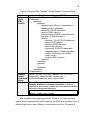
LIST OF TABLES ................................................................................................. V LIST OF FIGURES ..............................................................................................Vii
ABBREVIATIONS................................................................................................ iX ABSTRACT ......................................................................................................... Xi CHAPTER 1. INTRODUCTION ............................................................................ 1 1.1. Research Background ............................................................................... 1 1.2. Research Goal ........................................................................................... 2 CHAPTER 2. RELATED WORK ........................................................................... 3 2.1. Current Sensor Network Platforms ............................................................ 3 2.1.1. MoteWorks Platform ............................................................................ 3 2.1.2. Particle Platform .................................................................................. 4 2.1.3. μNode Platform ................................................................................... 4 2.2. Sensor Network Middleware Architectures ................................................ 5 2.2.1. MoteView Framework .......................................................................... 6 2.2.2. Atlantis Framework .............................................................................. 6 2.2.3. Decentralized Enterprise Systems Framework.................................... 6 CHAPTER 3. H-WSNMS ARCHITECTURE ......................................................... 8 3.1. H-WSNMS System Framework Overview .................................................. 8 3.2. Management Service and Application Layer ............................................ 12 3.2.1. Service Components ......................................................................... 13 3.2.2. MSA Metadata Repository................................................................. 14 3.3. Unified Gateway Layer ............................................................................. 16 3.3.1. UG Metadata Repository ................................................................... 18 3.3.2. Service Proxy .................................................................................... 19 3.3.3. Gateway Access ................................................................................ 19 3.3.4. Communication Mechanism .............................................................. 20 3.4. Mote Layer ............................................................................................... 20 3.5. H-WSNMS DB ......................................................................................... 20 3.6. System General Function Logical Flow .................................................... 21 CHAPTER 4. H-WSNMS KEY TECHNOLOGIES AND IMPLEMENTATION ..... 23 4.1. System Logical Architecture and Key Technologies Overview ................ 23 4.2. Mapping Fame ......................................................................................... 24 4.2.1. Mapping Model Technology .............................................................. 24 4.2.2. Virtual Command Set Mapping Model ............................................... 24 4.2.3. VCSMM Application Case Discussion ............................................... 27
iv
Page
4.3. Access Adaption ...................................................................................... 30 4.3.1. Unified Gateway Access Technology ................................................ 30 4.3.2. Unified Gateway Access Model ......................................................... 32 4.4. H-WSNMS Implementation ...................................................................... 33 4.4.1. H-WSNMS Software Architecture Overview ...................................... 33 4.4.2. System User Interface Design ........................................................... 35 4.4.3. XML Template and Definition ............................................................ 35 4.4.4. Data Structure and Definition ............................................................ 40 CHAPTER 5. H-WSNMS CASE STUDY ............................................................ 42 5.1. Experiment Hardware .............................................................................. 42 5.2. Software Platform .................................................................................... 45 5.2.1. Client Tier .......................................................................................... 45 5.2.2. Specific Gateway Middleware ........................................................... 46 5.3. Main Functions Overview ......................................................................... 48 5.3.1. Monitoring Function and Demo ......................................................... 50 5.3.2. Configuration Function and Demo ..................................................... 54 5.3.3. Reprogram Function and Demo ........................................................ 59 5.3.4. Data Collection Function and Demo .................................................. 64 5.4. XServe’s Extension .................................................................................. 69 CHAPTER 6. FUTURE WORK ........................................................................... 72 LIST OF REFERENCES .................................................................................... 74 APPENDICES
Appendix A ..................................................................................................... 77
Appendix B ..................................................................................................... 79
Appendix C ..................................................................................................... 84
Appendix D ..................................................................................................... 86
Appendix E ..................................................................................................... 88
v
LIST OF TABLES
Table
Page
Table 3.1 Virtual Command Category and Specification of VCS ........................ 15 Table 4.1 General Wrapped XML Format ........................................................... 29 Table 4.2 Wrapped XML Template File and Mapped Command String ............. 36 Table 4.3 Specification of Code .......................................................................... 37 Table 4.4 Data Collection Service Configuration XML Template File ................. 39 Table 4.5 Monitoring Service Configuration XML Template File ......................... 40 Table 5.1 Sensor Boards and Motes .................................................................. 44 Table 5.2 Monitoring Request XML File and Mapped Command String ............. 51 Table 5.3 Configuration Request XML File and Mapped Command String ........ 56 Table 5.4 Reprogram Request XML File and Mapped Command String ............ 61 Table 5.5 Data Collection Request XML File and Mapped Command String ..... 66 Appendix Table
Table A.1 Parameters Definition ......................................................................... 77 Table A.2 Command Category and Specification of VCS ................................... 78 Table B.1 XServe Command Line Parameters ................................................... 79 Table B.2 XServe Configuration Command Line Parameters ............................ 80 Table B.3 XServeTerm Line Parameters ............................................................ 80 Table B.4 XServeTerm Available Parameters .................................................... 81 Table B.5 XCommand Categories and Description ............................................ 82 Table B.6 XServe Reprogram Line Parameters ................................................. 82 Table B.7 XOtap Command Arguments ............................................................. 83 Table C.1 Monitoring ServiceID Definition .......................................................... 84 Table C.2 Configuration ServiceID Definition ..................................................... 84
vi
Appendix Table
Page
Table C.3 Reprogram ServiceID Definition ......................................................... 85
Table C.4 Data Collection ServiceID Definition .................................................. 85 Table D.1 DataTable H-WSNMS_ServicInfor ..................................................... 86 Table D.2 Datatable H-WSNMS_PlatformState.................................................. 86 Table D.3 Datatable H-WSNMS_SocketInfor ..................................................... 87 Table D.4 Datatable H-WSNMS_GatewayConfig ............................................... 87 vii
LIST OF FIGURES
Figure
Page
Figure 2.1 Sensor Platform: MICAz ...................................................................... 3 Figure 2.2 Sensor Platform: Particle ..................................................................... 4 Figure 2.3 Sensor Platform: μNode ...................................................................... 5 Figure 3.1 H-WSNMS System Architecture .......................................................... 9 Figure 3.2 H-WSNMS with Virtual Command Set............................................... 11 Figure 3.3 Management Service and Application Layer ..................................... 13 Figure 3.4 Unified Gateway Layer ...................................................................... 17 Figure 3.5 General control and status information flow for Generic Functions ... 22 Figure 4.1 H-WSNMS System Logic Architecture .............................................. 23 Figure 4.2 Virtual Command Set Mapping Module (VCSMM) ............................ 26 Figure 4.3 VCSMM Mapping Flow ...................................................................... 27 Figure 4.4 VCSMM Application........................................................................... 28 Figure 4.5 Comparison of Service Access Modes .............................................. 30 Figure 4.6 H-WSNMS Software Design .............................................................. 34 Figure 5.1 Mote Hardware .................................................................................. 43 Figure 5.2 Three-tier architecture instantiation based on XServe ....................... 45 Figure 5.3 Gateway Middleware: XServe ........................................................... 46 Figure 5.4 User Profile of H-WSNMS ................................................................. 49 Figure 5.5 “Monitoring” Command Logical Flow ................................................. 50 Figure 5.6 “Monitoring” UI ................................................................................... 52 Figure 5.7 Demo of “Monitoring” ......................................................................... 53 Figure 5.8 “Configuration” Command Logical Flow ............................................ 54 Figure 5.9 “Configuration” UI .............................................................................. 58
viii
Figure
Page
Figure 5.10 Demo of “Get Config” ...................................................................... 58 Figure 5.11 “Reprogram” Command Logical Flow .............................................. 59 Figure 5.12 “Reprogram” UI ............................................................................... 63 Figure 5.13 Demo of “Query” .............................................................................. 63 Figure 5.14 “Data Collection” Command Logical Flow ....................................... 64 Figure 5.15 “Data Collection” UI ......................................................................... 68 Figure 5.16 Demo of “Data Collection” ............................................................... 68 Figure 5.17 Demo of “New Data Collection” ....................................................... 69 Figure 5.18 XServe Command Flow Illustration [2] ............................................ 70 Figure 5.19 XServe Configuration Command Extension .................................... 71 Appendix Figure
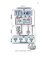
Figure E.1 the Whole Design of H-WSNMS ....................................................... 88 ix
ABBREVIATIONS
ABBREVIATIONS
DESCRIPTION
GW
Gateway
GWS
Gateway Set
H-WSNMS
Heterogeneous Wireless Sensor
Networks Management System
MR
Metadata Repository
MSA
Management Service and Application
OTAP
Over-the-air Programming
SC
Service Component
SOA
Service Oriented Architecture
TC
Target Command
TCS
Target Command Set
UG
Unified Gateway
UGA
Unified Gateway Access
VC
Virtual Command
VCA
Virtual Command Attributes
x
VCAS
Virtual Command Attributes Set
VCC
Virtual Command Category
VCS
Virtual Command Set
VCSMM
Virtual Command Set Mapping Model
WSN
Wireless Sensor Network
WSNs
Wireless Sensor Networks
XML
Extensible Mark-up Language
xi
ABSTRACT
Yu, Qun. M.S., Purdue University, August, 2010. Design and Implementation of
Web-based Data and Network Management System for Heterogeneous Wireless
Sensor Networks. Major Professor: Yao Liang.
Today, Wireless Sensor Networks (WSNs) are forming an exciting new area
to have dramatic impacts on science and engineering innovations. New WSNbased technologies, such as body sensor networks in medical and health care
and environmental monitoring sensor networks, are emerging. Sensor networks
are quickly becoming a flexible, inexpensive, and reliable platform to provide
solutions for a wide variety of applications in real-world settings. The increase in
the proliferation of sensor networks has paralleled the use of more
heterogeneous systems in deployment. In this thesis, our work attempts to
develop a new network management and data collection framework for
heterogeneous wireless sensor networks called as Heterogeneous Wireless
Sensor Networks Management System (H-WSNMS), which enables to manage
and operate various sensor network systems with unified control and
management services and interface.
The H-WSNMS framework aims to provide a scheme to manage, query,
and interact with sensor network systems. By introducing the concept of Virtual
Command Set, a series of unified application interfaces and Metadata (XML
files) across multiple WSNs are designed and implement the scalability and
flexibility of the management functions for heterogeneous wireless sensor
networks, which is demonstrated though through a series of web-based WSN
management Applications such as Monitoring, Configuration, Reprogram, Data
xii
Collection and so on. The tests and application trials confirm the feasibility of our
approach but also still reveal a number of challenges to be taken into account
when deploying wireless sensor and actuator networks at industrial sites, which
will be considered by our future research work.
.
1
CHAPTER 1. INTRODUCTION
1.1. Research Background
A wireless sensor network (WSN) [1] consists of spatially distributed
autonomous sensors cooperatively monitor physical or environmental conditions,
such as temperature, sound, vibration pressure motion or pollutants. The
development of wireless sensor networks (WSNs) was motivated by military
applications such as battlefield surveillance. They are now used in many
industrial and civilian application areas, including industrial process monitoring
and control, machine health monitoring, environment and habitat monitoring,
healthcare applications, home automation and traffic control and so on.
Wireless Sensor Networks have become an emerging new research area in
the distributed computing environment. It plays an important role in the pervasive
computing to support a wide range of applications of the daily life in future. So
far, as heterogeneous WSNs are being widely deployed for various applications,
we are faced with a new challenge of network management for heterogeneous
WSNs. On one hand, current available WSN management tools are either
application specific, or platform specific, thus suffering from the lack of reusability
in heterogeneous WSNs management environment. On the other hand, to
develop a new WSN management system for heterogeneous WSNs from scratch
is time consuming and may not be feasible. Motivated by such a challenge, a
major impediment in the integration process is represented by the variety of
customized platforms and proprietary technologies. In this thesis, we propose a
unique, open, scalable and flexible WSN Management Comprehensive
Application Platform targeted for Heterogeneous WSNs Management System.
2
Our prototype system H-WSNMS provides a Web-based Data and Network
Management Environment for Heterogeneous Wireless Sensor Networks.
This research topic is very important to allow large-scale heterogeneous
WSNs to be effectively and easily managed and operated in the real-world tasks
and applications.
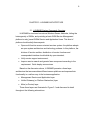
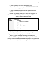
1.2. Research Goal
In this thesis, our main goal is to put forward a Heterogeneous WSNs
management system solution scheme and implement it based on a prototype
environment. This system should have the following features as described:
•
A unique, open, scalable and flexible WSN Management Comprehensive
Application Platform Architecture
•
A Service Oriented WSN management platform
•
A scalable Unified Gateway across multiple WSNs
In the design of our H-WSNMS architecture, some key component designs
are involved, such as Service Mapping design and Unified Gateway Access
design. In this thesis, we adopted the application of the Extensible Mark-up
Language (XML) which enables a new level of interoperability for heterogeneous
IT systems.
Using a common reference model improves this process and leads to
Virtual Command Set Mapping Model (VCSMM): Service Mapping. The results
can be used immediately to configure mediation layers integrating services into
an overall service oriented architecture. Besides, the Unified Gateway Access is
designed for integrating various different wireless sensor platforms and
accessing the third part gateway interfaces with other standards, which is flexible
and extendable.
3
CHAPTER 2. RELATED WORK
2.1. Current Sensor Network Platforms
2.1.1. MoteWorks Platform
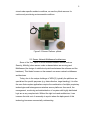
Crossbow [4] was one of the first suppliers of the Berkeley-style MICA
motes [4] which employ the TinyOS operating system. Follow on products
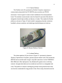
include the MICA2 [4] (868/916 MHz) and MICAz (2.4 GHz) motes as shown in
Figure 2.1, and the Intel-designed IMOTE2. Crossbow also makes a software
design platform for its hardware called MoteWorks.
The MICA2 Mote is a third generation mote module used for enabling lowpower, wireless sensor networks. The MICA2 processor radio is fully supported
by the MoteWorks Software Platform.
MICAz is a wireless sensor network mote developed by Crossbow
Technology. The device is built upon the IEEE 802.15.4 standard. It is one of the
most commonly used mote system in the world.
Figure 2.1 Sensor Platform: MICAz
4
2.1.2. Particle Platform
The Particle node [13], produced by Particle Computer, comprises a
communication board with the PIC18f6720 microcontroller and TR1001
transceiver. Various types of sensors can be attached to the communication
board. The wireless communication uses the AwareCon protocol [20], which is
designed to handle high mobility and density of nodes. This makes the Particle
platform as shown in Figure 2.2 well suited for equipping chemical containers
handled by human operators and checking potential dangerous situations.
Figure 2.2 Sensor Platform: Particle
2.1.3. μNode Platform
The μNode platform [14] as shown in Figure 2.3, produced by Ambient
Systems, represents a low-power, general purpose sensor node, built around the
MSP430 microcontroller and a single- chip radio transceiver for the 433/868/915
MHz ISM band. After deployment, the μNodes self-organize into a multi-hop
network, through which data can be routed back and forth to a designated sink
node. This platform is ideal for building large-scale sensing infrastructures that
can function unattended for long periods of time. Since many chemicals must be
5
stored under specific ambient conditions, we use the μNode sensors for
continuously monitoring environmental conditions.
Figure 2.3 Sensor Platform: μNode
2.2. Sensor Network Middleware Architectures
Some of the "hot" topics in WSN software research include such as
Security, Mobility (when sensor nodes or base stations are moving) and
Middleware (the design of middle-level primitives between the software and the
hardware). This thesis focuses on the research on sensor network middleware
architectures.
Today, due to the unique challenge of WSN [2], typically the platforms are
specialized for specific purposes (e.g. data collection, target tracking), it is often
the case that complex applications require the combination of multiple proprietary
technologies and heterogeneous wireless sensor platforms. As a result, the
management, monitoring and administration of a system with highly distributed
logic are a very complex task. Without the right tools and architecture, it can
increase the total cost of ownership to a point where the deployment of this
technology becomes commercially uninteresting.
6
2.2.1. MoteView Framework
MoteView [5][9] presents a scalable software framework for managing,
monitoring, and visualizing sensor network deployments developed by
Crossbow. It provides tools to the users to visualize results from a sensor
network. Readings arriving from the network are stored in a relational database.
The sophisticated interface is used to check the motes readings on the fly,
visualize the topology, produce graphs from selected motes, check their status
and export the readings to a spreadsheet.
2.2.2. Atlantis Framework
The Atlantis Framework [15] is based on TinyML but addresses several of
its shortcomings. The basic elements are the same, i.e., it can describe fields,
platforms, and sensors. Additionally, the Atlantis Framework adds data handling
abstractions, and a query field for more detailed queries. It makes further
improvements by defining a field task object which can handle asynchronous
data retrieval. For this purpose, it adds an additional data broker which handles
the tasks, and specific broker behaviors to describe how to handle the task itself.
As a nice roundup, the Atlantis Framework adds data filters and event
subscription possibilities. On the downside, there is not a standard way to
manage the sensor systems since a registry does not exist.
2.2.3. Decentralized Enterprise Systems Framework
The overall architecture of the Decentralized Enterprise Systems framework
[11][12] used a service-oriented architecture (SOA) as a platform construct.
SOA architecture is very helpful in solving the issues in the design of the
management system. The integration efforts are minimized by hiding much of the
implementation details and exposing only the functionality of the WSN in use.
The management also is simplified because the logic is encapsulated in services
with a manageable granularity. The services can be deployed, removed, or
7
upgraded from a central location to adapt the system to the business
requirements. In this thesis, we focus on the integration of various WSN
platforms for management and operation purpose. SOA architecture based on
Web services technology recently have become popular for building complex yet
flexible enterprise Web-based Management Systems.
8
CHAPTER 3. H-WSNMS ARCHITECTURE
3.1. H-WSNMS System Framework Overview
H-WSNMS is structured on various Wireless Sensor Networks, hiding the
heterogeneity of WSNs, and providing a basic WSN Service Management
platform to web_based WSNs Service and Application Users. This kind of
platform should satisfy three aspects:
•
Open multi-function access oriented services system: the platform adopts
an open system architecture and technology scheme. In this platform, the
division of function entities, distribution of service functions and
corresponded interface should abide by open standard;
•
Unify service support environment;
•
Improve service search and generic fame component according to the
requirement: Quick deploy new services.
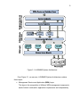
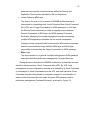
Based on the discussion above, H-WSNMS presents a three-layer
architecture that accommodates different sensor platforms and exposes their
functionality in a uniform way to the business application.
•
Management Service and Application layer
•
Unified Gateway (or Platform Abstraction) layer
•
Mote (or Device) layer
These three layers are illustrated in Figure 3.1 and discussed in detail
throughout the following subsections.
9
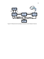
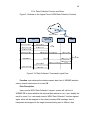
Figure 3.1 H-WSNMS System Architecture
From Figure 3.1, we can see, H-WSNMS System Architecture contains
three layers:
•
Management Service and Application (MSA) Layer
This layer is the composition of different WSN management components,
each of which is tailored for application requirements and independently
10
performs some specific functions that are defined by Service and
Application Client and are described in Service Repository.
•
Unified Gateway (UG) Layer
This layer is the core of our proposed H-WSNMS architecture that is
responsible for interpreting each Virtual Command from Virtual Command
Set (VCS) into a Target Command(s) for WSN gateway(s). In this layer,
the Service Proxy component provides a mapping function between
Service Components in MSA layer and WSN gateway Command
Service(s), displaying the multiple management functions accessing
multiple WSN applications. Besides, the two control components,
Gateway Access component and Communication Mechanism component,
build the communication bridge between MSA layer and Mote layer,
responsible for transmitting the Target Command(s) to WSN gateways.
•
Mote Layer
This layer consists of, in general, multiple heterogeneous WSN gateways
associated with their preliminary management Command Services.
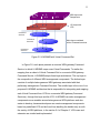
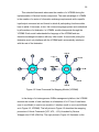
During the above discussion H-WSNMS architecture, an important concept
should be introduced here: Virtual Commands Set (VCS). By VCS, each
management service component is deemed to be realized by a Virtual Command
or a sequence of Virtual Commands from the VCS, and each individual Virtual
Command could be either partially or completely mapped to a combination of
some existing Command Services under the given WSN gateway (with its
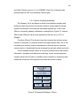
preliminary management Command Services), as shown by Figure 3.2.
11
SC1
SC2
VCSMM
SC3
MSA Layer with
components
UG Layer with
VCS
Command
Service1
Command
Service2
Mote Layer consisted
with n Command services
Command
Service n
Figure 3.2 H-WSNMS with Virtual Command Set
In Figure 3.2, each plane presents a concrete WSN gateway Command
Service, to which H-WSNMS maps some Virtual Commands. To realize the
mapping from a subset of Virtual Command Set to a concrete WSN gateway
Command Service, H-WSNMS adopts three-layer architecture. The top layer is
the composition of different WSN management components. The bottom layer
consists of multiple heterogeneous WSN gateways associated with their
preliminary management Command Services. The middle layer is the core of our
proposed H-WSNMS architecture that is responsible for interpreting and mapping
each Virtual Command from VCS into a concrete WSN gateway Command
Service(s), through this layer and the VCS, H-WSNMS can make management
components more reusable across heterogeneous WSN platforms and also
easier to develop, because developers can create management components
based on predefined VCS and be freed from handling the details early on with
the variety of WSN platforms, in the section 5.4 of Chapter 5, VCS reuse and
extension are studied and implemented.
12
The advantage of VCS is that when a minor change on the commands
service happens, just update some parameters configuration or add new
parameters to complete new configuration in the interpreter. For understand this
better, the content and format of VCS is defined in the Table 3.1. For this
Wrapping and Interpreting procedure of VCS, we call it Virtual Command Set
Mapping Model (VCSMM), which is discussed as one of key technologies in
Chapter 4. The core UG layer in our proposed H-WSNMS architecture, working
as an extensible and scalable interface between management components and
concrete WSN gateway(s), provides an Access Adaption to specific WSN
gateways, which also is discussed as another key technology in Chapter 4.
Besides, to illustrate implementation of the H-WSNMS architecture more
detail, in the Chapter 5, we will present an instantiation based on specific WSN
platform: Crossbow’s MoteWorks [6].
In the following sections, the three-Layer structure is analyzed layer by
layer.
3.2. Management Service and Application Layer
Management Service and Application (MSA) layer not only is able to provide
management functionality, but also benefit from the uniform interfaces offered by
the UG layer. In the Figure 3.3 gives us the detail about the MSA layer.
13
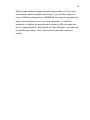
Figure 3.3 Management Service and Application Layer
There are two main parts in this layer:
•
Service Components
•
MSA Metadata Repository
It contains a series of metadata documents in following components:
o VCS Configuration
o Gateway Service Configuration
o Service Wrapper
3.2.1. Service Components
The MSA layer presents lots of various WSN management service
components, the arguments of which, i.e. User request, which is called as Virtual
Command in this system, are wrapped into Metadata XML file format stored in
Service Repository.
14
The main service components involve Monitoring component, Configuration
component, Reprogram component, Data Collection components and so on. The
detail design and implementation will be introduced in Chapter 5.
3.2.2. MSA Metadata Repository
MSA Metadata Repository (MSA MR) component is a DB of available
services configuration such as the VCS configuration, the target gateway service
configuration, and XML documents containing the service description and so on.
It is composed of the following parts:
•
VCS Configuration
A available file to define Virtual Command Category (VCC), which has two
aims: one is to more conveniently describe service components from MSA
layer; the other one is to help to automatically create socket
communication port for management services with same type, i.e. the
same type management services with the same WSN platform and same
WSN gateway will share a same socket communication port. The code of
port is composed of the code of VCC, the code of WSN platform and the
code of WSN gateway. The latter two codes are described and defined in
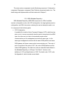
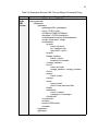
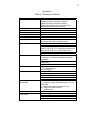
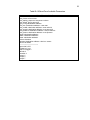
the Metadata Repository in UG layer. The Table 3.1 shows us the
definition of VCC and Specification of VCS. The detail code of VCC, refer
the Appendix A, which includes more details.
15
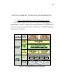
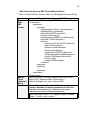
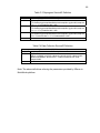
Table 3.1 Virtual Command Category and Specification of VCS
VCS
VC
Data
H_DataColl
Collection
VCS
H_DataColl
Monitoring
H_Monitoring
VCS
H_Monitoring
Configuration H_Config_Reconfig_SpRate
VCS
H_Config
H_Config_Reconfig_NID
Reprogram
Set
H_Repro
Others
•
Command
Function
Data
collection
Monitoring
sensor data
Set new
Sampling
Rate
SET_NODEID Assign
Node ID
SET_GROUP Assign a
H_Config_Reconfig_GID
Node to
new group
H_Config_Reconfig_CRate
Set
collection
rate
H_Config_Reconfig_ECollect
Immediately
perform a
data
collection
from WSN
and store it
to DB
……
……
……
RESET
H_Config_PM_RESET
SLEEP
H_Config_PM_SLEEP
WAKEUP
H_Config_PM_WAKEUP
……
……
……
H_Repro_Boot
H_Repro_Query
H_Repro_Load
……
……
SET_RATE
……
……
Gateway Service Configuration
A series of available files with format “.xml” or “.txt” configuring various
WSN gateway status information, spatial information, the available
16
gateway communication port information, and gateway middleware
parameters information and so on. The detail design of XML template is
shown as Table 4.3, Table 4.4 in Chapter 4.
•
Service Wrapper
It is a XML Wrapper responsible for describing service components in
MSA layer, i.e. wrapping VC(s) corresponding to these service
components with Metadata XML file format. The detail design of XML
template is shown as Table 4.2 in Chapter 4. These XML files in Service
Wrapper usually are sent to Service Proxy in UG layer to be mapped and
interpreted into a target command string authorized by specific WSN
gateways in the Mote layer.
3.3. Unified Gateway Layer
Owing to the difference of WSN gateways and diversity of command
parameters indentified by motes in different WSNs, during the design of Unified
Gateway (UG) layer, the system developers should statistics enough integrated
information from Mote Layer, the purpose of which are to transfer various valid
command strings to motes smoothly, to achieve gateways configuration correctly,
and to guarantee gateway communication mechanism work successfully and so
on. The design and implement of UG layer is not only a challenge but also an
opportunity. The Figure 3.4 shows us the detail about the UG Layer.
17
Figure 3.4 Unified Gateway Layer
UG layer is designed to harmonize different sensor platforms, i.e.
heterogeneous sensor platforms.
•
Responsibilities:
o Handle the proprietary WSN mechanisms
o Expose the service-oriented functionality through a standard
interface
•
Uniform Interface:
o Facilitates the integration of the new platforms via a simple
standardized mechanism
There are three main components in this layer:
•
UG Metadata Repository
It contains two type metadata documents as following:
o Platform Configuration
o Gateway Configuration
•
Service Proxy
A series of XML files in Service Wrapper are sent to Service Proxy in UG
layer to be mapped and interpreted into a target command string
authorized by specific WSN gateways in the Mote layer.
18
•
Gateway Access
It builds up the gateway middleware connection mechanism between UG
layer and Mote layer.
•
Communication Mechanism
Socket Client- Server model is adapted in this system, which becomes the
communication channel between MSA layer and Mote layer.
3.3.1. UG Metadata Repository
UG Metadata Repository (UG MR) is a series of available files to describe
the information about WSN platforms and their gateways. It has two functions:
one is to complete the respective configuration of WSN platforms, the
corresponding specific gateways and gateway middleware application interface,
and the other is to help to connect with mote layers through Gateway Access
component and Communication Mechanism component. As mentioned in
section 3.2.1, automatically created socket communication port for management
services with same type needs the information about the code of VCC, the code
of WSN platform and the code of WSN gateway. The latter two codes are
described and defined in the Metadata Repository in UG layer. The detail code
rules refer the Appendix A, which includes more details.
•
Platform Configuration
The target platform information is defined such as Platform Name and
Platform ID and the corresponding Gateway Code in these metadata files
•
Gateway Configuration
The corresponding Gateway Name, Gateway ID and Gateway middleware
application interface will be described in these metadata files
19
3.3.2. Service Proxy
It is a XML Parser responsible for systematic parsing and interpreting of the
Virtual Command(s) with XML format wrapped by Service Wrapper to the target
command strings indentified by the specific WSN gateways in Mote layer.
This Mapping processing is completed by Service Wrapper, presenting VCS
with XML format and Service Proxy, containing a group of Service Proxies, which
is command interpreter for a subset of VCS. That is to say, in H-WSNMS system,
the combination of Service Wrapper and Service Proxy is a key Mapping
Technology of H-WSNMS system implementation: Mapping Technology, which
will be discussed in section 4.2.
3.3.3. Gateway Access
Through a series of available files configuring various WSN platforms, their
different gateways information and relative gateway middleware information and
so on, Gateway Access component builds up a connection mechanism with the
specific gateway middlewares. The combination of MR component and Gate
Access component is another key technology of H-WSNMS system
implementation: Unified Gateway Access Technology, which will be discussed in
section 4.3.
It is responsible for connecting the available application interfaces from the
various different WSN gateway middlewares, take an instance of specific
gateway middleware XServe in Crossbow WSN platform MoteWorks, which
provides several different application interfaces such as XServe, XServterm and
XOtap and so on. Through these application interfaces, the mapped target
command(s) from Service Proxy is (are) sent to the specific WSN gateway(s) to
complete various WSN management or data collection functions. About Gateway
Middleware XServe will be introduced as an instantiation of system
implementation in Chapter 5.
20
3.3.4. Communication Mechanism
Communication Mechanism component adopts Socket Client- Server Model
to realize the communication between MSA layer and Mote layer. After Service
proxy interprets and parses Virtual Command(s) described by XML file, the
output mapped target command string(s) will be sent to the WSN gateway
through this Communication Mechanism component. The socket port is
automatically created based on the code of VCC, the code of platform and the
code of WSN gateway, in another words, these code information should be
defined at the beginning by system developers as illuminated in the Table.3.1,
Appendix A and Appendix B, the detail definition of Port No. (i.e. Socket Port) will
be introduced in section 4.4.3.
3.4. Mote Layer
The Mote Layer, the system hardware layer, building the real word wireless
sensor network or wireless sensor networks. Each wireless sensor network has
its own base gateway, communicating with its specific base station. The UG
Layer provides a Unified Interface and Communication Mechanism to access
every wireless sensor network to compete wireless sensor data and network
management.
3.5. H-WSNMS DB
H-WSNMS Database is a DB of available services, storing the updated
information from Mote Configuration and the updated Platform status, and the
motes data that can be retrieved from Wireless Sensor Networks through Date
Collection function. The PostgreSQL database technology helps us to complete
this part.
21
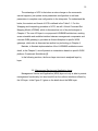
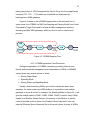
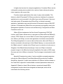
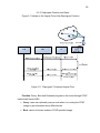
3.6. System General Function Logical Flow
After introduction of H-WSNMS Three-layer architecture and the
components in each layer, we can overview the whole system design like Figure
E.1 in Appendix E shows us.
Now we give the general control and status information flow for generic
functions in H-WSNMS system as illustrated in Figure 3.5. At the beginning,
Users send a request to Function components in the MSA Layer, then the
requesting information, i.e. Virtual Command(s), is sent to the UG layer and is
wrapped into XML file(s) as attribute values in the Service Wrapper, which is(are)
parsed and interpreted by the Service Proxy into the target command string(s)
identified by WSN gateway(s) in Mode Layer, after its(their) own interpreter(s),
then the WSN gateway(s) send the authorized command streams with binary
format to the Base Station(s), which broadcast them into motes in WSNs. So far,
the Requesting processing as the solid line shown has been completed, after
mote(s) receives and executes the commands, they will response the
corresponding information back to the WSN Base Station, and then the Base
station transfers this information to WSN gateways to translate and send the data
and WSN information back to Users through Unified Interface. During the
Response processing as the dash line shown, the retrieved data from WSNs
motes and the updated information about platform status are stored into HWSNMS DB. We will overview several functions in detail such as Monitoring,
Reconfiguration and Reprogram one by one in the later Chapter 5 to show the
different logic flows of various management functions.
22
Figure 3.5 General control and status information flow for Generic Functions
23
CHAPTER 4. H-WSNMS KEY TECHNOLOGIES AND IMPLEMENTATION
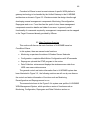
4.1. System Logical Architecture and Key Technologies Overview
This Chapter will focus on discussion of the key technologies and system
implementation. Figure 4.1 shows us the Logic Architecture of H-WSNMS, which
involves two key parts during the design and implement of H-WSNMS: Mapping
Fame and Access Adaption.
Figure 4.1 H-WSNMS System Logic Architecture
24
Mapping Fame and Access Adaption are key parts in the design and
implementation of H-WSNMS, involving two main technologies as follows:
•
Mapping Model Technology
•
Unified Gateway Access Technology
4.2. Mapping Fame
4.2.1. Mapping Model Technology
During the design, the goal of Mapping Model is to map concepts, command
elements and relationships from the virtual commands to the target command set
in order to implement a service from Client.
•
Conceptual Mapping: Conceptual mapping is the listing of all existing
Virtual commands.
•
Attribute mapping: This logical step is to identify similar attributes. At this
level special attention has to be paid to synonyms, homonyms and the
inherent context of attributes. Two attributes are said to be equal when
they describe the same real world property.
•
Content Mapping: Most mapping efforts tend to conglomerate content
mapping with attribute mapping. Two values are said to be identical if they
can be derived from one another. At the attribute level, equivalence
between real world properties is established while the content level deals
with how attribute values are derived from one another.
The complexity of any mapping effort is directly related to the complexity of
these individual components.
4.2.2. Virtual Command Set Mapping Model
In previous traditional design, Command one-to-one Model was adopted in
the WSN management system. The flexibility and reuse have been neglected
25
and more efforts have been rightly directed at identifying and resolving mapping
issues. In order to avoid those same pitfalls, the Virtual Command Set Mapping
Model (VCSMM) multi-to-one-to-multi process must include rules and guidelines
addressing these issues. For the solution to be flexible and scalable, the
implementation of a valid Virtual Command Set multi-to-one-to-multi Mapping
must be included:
•
Virtual Commands: For any Service Component (SC) containing a list of
independent enumerated Virtual Commands VC1, VC2…, VCn
susceptible of being exchanged based on definition of VCC, there must be
an exhaustive set VCS of unique enumerated values in the reference
function model (MSA service component) such that VCS = {VC1,VC2…,
VCn}. VC can be extended as more service components are added to the
federation.
•
Properties: For any Service Component containing a list of independent
Virtual Command Attributes (VCA) referring the WSN gateway middleware
information, with XML file format, VCA1, VCA2,…, VCAn susceptible of
being exchanged based on the Attribute parameters, there must be an
exhaustive set VCAS of attributes in the reference service function model
such that VCAS = { VCA1, VCA2…, VCAn}. CAS can be extended based
on the updation of this function component.
•
Associated Concepts: For any set of Objects GWS, linked through a
relationship describing the Target Command concepts TC1,TC2…, TCn,
there must be an exhaustive set TCS of concepts in the reference WSN
gateway model such that TCS = { TC1, TC2…, TCn}.
•
Gateways: For real Gateway objects GW1, GW2…GWm susceptible of
being exchanged according to Gateway Configuration information, there
must be a set GWS of independent objects in the reference WSN platform
model such that GWS = {GW1, GW2…GWm}. Objects can be added as
new gateways join the federation.
26
This extended framework advocates the creation of a VCSMM during the
implementation of Service function component. The main advantage of VCSMM
is the creation of a series of information exchange requirements with a specific
input/output command set and format to which all participating function models
have to abide. It becomes, in fact, the common language spoken and understood
by all members of a federation. In VCSMM, models interoperate through the
VCSMM. Each model understands the language of the VCSMM and can
therefore exchange information with any other model. A new model joining the
federation must only interface with the VCSMM and it automatically interfaces
with the rest of the federation.
Figure 4.2 Virtual Command Set Mapping Module (VCSMM)
In the design of a heterogeneous WSNs management platform, the VCSMM
reduces the number of total interfaces in a federation of N VC from N interfaces
(one to one Model) in one-to-one model to 1 interface (multi to one to multi Model
as in Figure 4.2, VCSMM). The left picture in Figure 4.2 describes the wrapping
procedure of Virtual Commands {VC1,VC2,…VCn} formatted by Service
Wrapper into VCAS (XML file); The right picture in Figure 4.2 illustrates us the
27
parsing procedure of VCAS interpreted by Service Proxy into the scoped target
concepts {TC1, TC2…, TCn} which can indentified and interpreted by
heterogeneous WSN gateways.
Figure 4.3 shows us the VCSMM mapping flow in the red break line. In
some sense, the VCSMM is a XML file Wrapping and Parsing Model from Virtual
Command to Target Command to achieve multiple management functions
accessing multiple WSN gateways, which is a kind of multi-to-one-to-multi
process.
Figure 4.3 VCSMM Mapping Flow
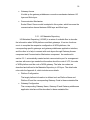
4.2.3. VCSMM Application Case Discussion
During the application of VCSMM, considering providing Users a more
friendly and humanized management and maintenance of WSNs, H-WSNMS
system gives user several options to select:
•
Saving Power Mode
•
Speeding Mode
•
Saving Power and Speeding Mode
Usually, when monitoring WSNs, we should consider the above three
situations, for some certain type WSN platform, it is possible to use multiple
gateways to cover all motes, for example, the Speeding Mode in Figure 4.4, it will
give the multiple options (COM1, COM3, COM5, COM7) to select, every COMn
stands for a Wireless Sensor Network, the purpose of this Mode is to quickly
cover all possible motes in these four Wireless Sensor Networks if user can
select all Wireless Sensor Networks. But in this mode, plenty of power in WSNs
28
would be wasted and even lost without any benefit, although this way can
improve and increase the data link speed to get more information such as the
sampling data and other configuration and platform status than other modes,
there exists a potential flaw: power wastage. On the other hand, if just
considering power saving, only one WSN is selected, like the Saving mode
(COM5) shown in Figure 4.4, the limited motes covered by one WSN can be
visited, although this mode can save the power of this WSN, it cannot guarantee
to access all possible motes, so its limitation is obvious. Based on the analysis
on the previous two modes, the third mode “Saving Power and Speeding Mode”
becomes a comprehension option for users, which provides maybe a better not
the best option: COM3 and COM5 as shown in the picture. No matter which
method is best option, it depends on user requirement, so system provides
monitoring mode configuration to satisfy users. The mode configuration is
described by XML file. The available WSN gateway power situation and cover
performance should be done some statistics and represented in metadata file.
Figure 4.4 VCSMM Application
Figure 4.4 gives us an example to statement these three options:
29
•
“Saving Power Mode” has only one gateway port (COM5)
•
“Speeding Mode” has four gateway ports (COM1, COM3, COM5, COM7):
recommend to select all at one time
•
“Saving Power and Speeding Mode” has two gateway ports (COM3,
COM5): recommend to select these two at one time
No matter how much the gateway ports to select, each function has one
XML file created by Service Wrapper with the following format in Table 4.1:
Table 4.1 General Wrapped XML Format
Request
XML
Format
….
<gateways>
<gateway>
<device>COM1<device>
……
</gateway>
<gateway>
<device>COMi<device>
……
</gateway>
</gateways>
….
After interpreted by Service Proxy, output the number of target command
string is same as the number of gateways described in XML file.
Table 4.4 in section 4.4 describes the Gateway Monitoring Service
Configuration XML file design, which provides a XML template of multi WSN
platforms with multi available specific gateway communication Ports under above
three different modes, displaying the system design flexible and scalable.
30
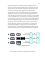
4.3. Access Adaption
4.3.1. Unified Gateway Access Technology
H-WSNMS provides a Unified Interface in the Unified Gateway Layer,
completing a unified accessing of one or more gateways. Owning to the diversity
of senor network services provided by various gateways and the variety of
accessing protocol standard provided by different sensor networks, different type
services have their own functions such as monitoring, reconfiguration,
reprogram, data collection and so on.
Figure 4.5 Comparison of Service Access Modes
Figure 4.5 displays the Traditional Service Access Mode and Unified Access
Mode, Traditional Service Access Mode (Access Mode A) make the interface
between Service Platform and WSN gateways over many, which obviously is not
good for service extension and update. Otherwise, Unified Access Mode (Access
31
Mode B) can overcome the above defect and undoubtedly bring the following
advantages to Service development.
We call this Unified Access Mode as Unified Gateway Interface, which is
unique channel between the Service Management Platform and the Wireless
Sensor Networks, being responsible for interoperating between different service
and different service gateway and implementing the Adaptation of multi-service
and multi-gateway. UG provides a means of real-time two-way communication
between two data terminal installations: after the mapped target command
outputs from Service Proxy, the UG MR component, UG Access component and
Communication Mechanism component work together to complete the
processing of the target commands’ accessing heterogeneous WSNs, then the
specific gateways sends the request to the WSN motes, through this way
building a real-time interoperation.
•
Reduce the implication on platform services from changes of GW:
From the services in platform, what they face is not complex multiple
gateway interfaces any longer, but a standard interface provided by a
Unified Gateway (UG). Thus, when a gateway with updated version or a
new gateway accesses, only revise and increase the corresponding
configuration component (Gateway Configuration) in UG based on the
updated or new gateway protocol, the platform services will not be
impacted;
•
Improve the reliability of platform accessing: After applying the Unified
Access Technology to the service platform, UG becomes a unique
channel between the Comprehensive Application Platform and Wireless
Sensor Networks, which can better manage and monitor the relatively
messy interfaces in Traditional Access Mode and more effectively improve
the reliability of platform accessing;
•
Promote the quick development and deployment of services: When
exploring new services, need not consider the compatibility of multiprotocol based on a completed function Unified Gateway, thus, the period
32
of development and deployment of new applications is shortened along
with;
•
Enhance the general applicability of developed services: The
development of new services does not involve the adaptable problem of
the specific gateway, which enhance the applicability of services.
•
Reduce the number of the inner interface: Reduces the number of total
interfaces from N x M interfaces to M+1 interfaces, N is the number of the
services, M is the number of gateways.
Based on the above research and analysis, there are several key points in
the design and implement of UG:
•
UG Modular Design: having characters such as unity, scalability and so
on. UG is designed as a set of components, including Gateway
Configuration component, Service Repository component, and Socket
Communication component and so on.
•
API Encapsulation: According to the access requirement, make
corresponding adaption of this Unified Gateway interface.
•
Protocol Adaption:
o Socket: System adapted the Client-Server Socket Communication
Model to pass the target command string(s) mapped in UG layer
between MAS layer and the specific gateway(s) in Mote layer. The
Code design of Socket Port is discussed in
4.3.2. Unified Gateway Access Model
Unified Gateway (UG) is one of the core components in H-WSNMS, one
side, it links to the service platform, other side, and it communicates with different
real wireless sensor gateways. UG adopts flexible Loosely-coupled Design
thinking, satisfying the requirement of extension and updation. The whole running
environment is divided into the following two parts:
33
•
Gateway Configuration: a series of XML files which provide the
information of gateway interactivity and real-time monitoring and control, in
the future, the system developer can design a Web-based or MS
Window-based Virtualization Tool to complete gateway configuration;
•
Gateway Access Loader: Through this Loader, some certain gateway
can be start-up, shut-down and configuration. When a gateway starts up,
through gateway configuration component, the configuration information or
the prescribed configuration files can be input manually.
•
Third-Part Gateway Interface: For extension of other standard gateway
interface, this interface can be extended by the future developer, which
provides a flexible interface to other Wireless Sensor Management
Services and Applications Platforms.
4.4. H-WSNMS Implementation
4.4.1. H-WSNMS Software Architecture Overview
A three-layer Architecture based on J2EE Frame is applied in the design of
H-WSNMS Service Comprehensive Application Platform. Figure 4.6 displays HWSNMS Software Architecture.
34
Figure 4.6 H-WSNMS Software Design
Service Logic Layer is responsible for the implementation of all logical
functions in the whole management system, which is designed by Java
Technology. JSP Presentation layer is responsible for the implementation of all
Web pages such static User Interfaces and other dynamical web pages.
J2EE Framework in Web-based Management Platform has following
features:
•
Portability of Web-based component
o Over different vendor platform
o Over different operational environment
o Portability, Scalability, Reliability
•
Leveraging existing J2EE programming models for service implementation
35
•
Easy to program and deploy
o High-level Java APIs
o Use existing deployment model
4.4.2. System User Interface Design
This section is mainly developed with JSP and Java Script technologies.
There are some demos displayed by an instantiation in the Chapter 5.
4.4.3. XML Template and Definition
Based on the above the key technologies and core models, in this section,
we will focus on the implementation of the whole system.
As we know, the design and implementation of VCSMM becomes the most
important part in H-WSNMS system, one side, the Service Wrapper is
responsible for wrapping the virtual commands, automatically creating XML
template file(s) based on different Management Service Components; another
side, the Service Proxy is responsible for interpreting the XML file into the target
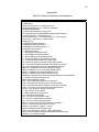
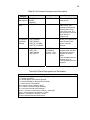
commands. The Table 4.2 is an example of wrapped XML template about Virtual
Command Set and final Mapped Target Command String. This XML template is
specific for of “Data Connection” Function, through which system can get the
WSN Gateway information that is responsible for receiving the target
command(s) and sending them to Mote layer and Database information which is
responsible for storing the responded data from motes in WSNs.
36
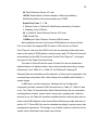
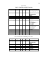
Table 4.2 Wrapped XML Template File and Mapped Command String
Function
Request
Node
XML
Format
Mapped
Target
Command
String
Note
Data Collection Request XML File
<?xml version="1.0" encoding="UTF-8"?>
< Datacollreq >
<gateways>
<gateway>
<gatewayname>XServe</ gatewayname>
<gatewayid>05</ gatewayid>
<serviceID>105100</serviceID >
<device>COM5</device >
<interfaceboard> MIB520</interfaceboard>
<baudrate >57600</baudrate >
<dbinfor>
<dbserver>149.166.32.252</dbserver>
<dbport>5432</dbport>
<dbname>IDAM</dbname>
<dbuser>tele</dbuser>
<dbpasswd>12345678</dbpasswd>
<databaseparsed>l</databaseparsed>
<xmlfile> XmlStream.xml</xmlfile>
<xmlp></xmlp>
<xmlport>9005</xmlport>
</dbinfor>
</gateway>
<gateway>
……
</gateway>
</gateways>
</Dataconnreq >
xserve –s=COM5 –b=57600 –dbserver=149.166.32.252 –
dbport=5432 –dbname=IDAM –dbuser=tele -l –
xmlfile=XmlStream.xml -xmlp –xmlport=9005
This is a General and Extendable file
Example: Available Command parameters for XServer
(Refer XServe Users Manual, in which there is the detail introduction
about various XCommand Arguments)
main parameters: xserve -s -b -dbserver -dbport -dbname dbuser -l -xmlfile -xmlp –xmlport
After completing the mapping procedure, Socket in UG Layer has been
applied as the communication method between the MAS layer and Mote Layer. A
different type function has a different communication port for it. We design a
37
socket port management mechanism to achieve this aim. The method is
described as following:
As mentioned in section 3.3.1, in which the Table 3.1 shows us the main
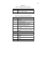
Command Category and Specification of VCS. The Table A.1 in Appendix A
gives us the detail definition of various parameters involved in the whole design
of H-WSNMS, including a series of code rules such as the code definition of
WSN platform, the code definition of WSN gateway and so on. The Based on the
Table A.1 or the following Table 4.2, we design the Definition of ServiceID, or
called as VCID, and Socket Port.
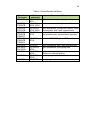
Table 4.3 Specification of Code
Parameters
PlatformID (extendable)
GatewayID (extendable)
GatewayCode (extendable)
VCS Code (extendable)
Definition
PlatformNo. N: 1~9
XX: 01~99
Y:1~9
00: H_DataColl
10: H_Monitoring
20: H_Config
60: H_Repro
70: H_others
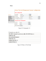
ServiceID code is composed of 6 digital numbers, which is used to tag each
VC:
PlatformID+GatewayID+GatewayCode+ VCC No.
Socket Port Code is made up of 4 digital numbers, which is used to tag
Socket Port and the XML file name:
PlatformID+ GatewayCode + VCC No.
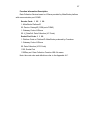
Following the code rule in Table A.1 or Table 4.2, take “Data Collection”
Function based on XServe provided by MoteWorks platform with specific
communication port COM5 as an example:
ServiceID Code: 1 05 1 00
1: PlatformID: MoteWorks produced by Crossbow
05: GatwayID: XServe (COM Port=COM5)
1: Gateway Code of XServe
38
00: Data Collection Service VC code
105100: DataCollection Function based on XServe provided by
MoteWorks platform with communication port COM5.
Socket Port Code: 1 1 00
1: Platform Code or PlatformID: MoteWorks produced by Crossbow
1: Gateway Code of XServe
00: H_DataColl: Data Collection Service VCS code
1100: Socket Port
1100Req.xml: Data Collection Function XML file name
Each application function for the same WSN platform has unique Socket
Port, so we name the wrapped XML file name of this function as Socket
Port+”Req.xml” and store this XML file into the corresponding folder with same
name as the name of WSN platform under the given path. The Service Proxy will
automatically find this XML file with name “Socket Port+”Req.xml” ” to interpret
and map it to the Target Command string.
The code of ServiceID and the code of Socket Port are not limited the 6
digital numbers or 4 digital numbers, they can be extended according to design
requirement, From Table A.1 or Table 4.2, the PlatformID, GatewayID,
GatewayCode are extendable and the extension of them can be completed in the
corresponding configuration files, which displays the scalability and flexibility of
system design.
In MSA layer, another component: Gateway Service Configuration
component, provides a series of XML files as shown in Table 4.3, Table 4.4 and
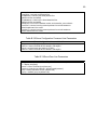
so on. The Table 4.3 describes Mote Data Collection Query Service information,
including sensor location, sensor status, sensor type, sampling rate, collection
rate and so on, the Table 4.4 describes available specific communication port for
some certain WSN platform under three different Monitoring modes discussed in
section 4.2.3. These XML files can be extended according to system sensor data
management requirement. This design is very flexible, based on which the future
system service developers can create new services.
39
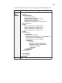
Table 4.4 Data Collection Service Configuration XML Template File
Function
Data Collection Service Configuration XML File
Config
XML
Format
<?xml version="1.0"?>
<sensorNet>
<BasicInformation>
<state>Indiana</state>
<county>Indiana1</county>
<siteName>Y_Indianapolis</siteName>
<NetType>Other</NetType>
<OriginalPoint Longitude="86" Latitude="39"/>
</BasicInformation>
<Scope>
<North Longitude="86" Latitude="39" />
<South Longitude="86" Latitude="38" />
<East Longitude="87" Latitude="38" />
<West Longitude="87" Latitude="39" />
</Scope>
<SensorNodes>
<SensorNode>
<NodeId>1465</NodeId>
<NodeLocation x-coordinate="1" y-coordinate="1"/>
<sensorType>model1</sensorType>
<sensorStatus>work</sensorStatus>
<canMeasure>
<Parameter>
<BaseTime>00:00:00</BaseTime>
<SampleRate>5000</SampleRate>
<CollRate></CollRate>
</Parameter>
</canMeasure>
</SensorNode>
<SensorNode>
…….
</SensorNode>
</SensorNodes>
</sensorNet>
Note
This is a General and Extendable file
40
Table 4.5 Monitoring Service Configuration XML Template File
Function
Config
XML
Format
Monitoring Service Configuration XML File
<?xml version="1.0" encoding="UTF-8"?>
<MonitoringServiceConfig>
<Platforms>
<Platform>
<PlatformName>MoteWorks</PlatformName >
<GatewayName>XServe</GatewayName >
<Modes>
<Mode>Power</Mode>
<AvailablePort>COM5</ AvailablePort >
<Mode>Speed</Mode>
<AvailablePort>COM1, COM3, COM5, COM7</ AvailablePort >
<Mode>PowerSpeed</Mode>
<AvailablePort>COM3, COM5</ AvailablePort >
</Modes>
</Platform>
<Platform>
<PlatformName>Praticle</PlatformName >
<GatewayName>xxxx</GatewayName >
<Modes>
<Mode>Power</Mode>
<AvailablePort>xxxx</ AvailablePort >
<Mode>Speed</Mode>
<AvailablePort>xxxx, xxxx, xxxx, xxxx</ AvailablePort >
<Mode>PowerSpeed</Mode>
<AvailablePort>xxx, xxx</ AvailablePort >
</Modes>
</Platform>
<Platform>
……
</Platform>
</ Platforms >
</ MonitoringServiceConfig >
Note
This is a General and Extendable file
4.4.4. Data Structure and Definition
Considering that some certain function such as “Data Collection” function
need to synchronize the wireless sensor data, and “Configuration” function
maybe update platform or WSN gateway status information, these dynamical
data and status information management should stored in the system own
database. The HWSNMS DB is responsible for storing and maintaining these
41
data and configuration information, which is designed and implemented through
using the PostgreSQL database technology.
Some Datatables are described in Appendix D.
42
CHAPTER 5. H-WSNMS CASE STUDY
5.1. Experiment Hardware
In this chapter, we will discuss the H-WSNMS XServe [7] Instantiation
based on HIDE system in detail. Before the discussion of H-WSNMS Application
design, we should introduce the experiment environment.
Hardware is composed of three parts: Mote, Sensor board and
Programming board, as shown in the Figure 5.1.
Mote Type: Micaz
•
Processor
ATmega 128L
•
Freq.
2400 MHz to 2483.5 MHz
•
Range Outdoor/indoor
75 m to 100 m/20 m to 30 m
•
Onboard Sensor /extend board
None /Yes
Sensor Board: MTS310
•
Light, Temperature, Microphone, Buzzer, 2-axis Accelerometer and 2-axis
Magnetometer Sensor
•
Compatible with IRIS/MICAz/ MICA2 Processor/ Radio Boards
Gateways: MIB520+Mote
•
Programming board MIB520 (Upload NesC file to mote (wire)
•
Communicate with mote (wireless)
•
Send NesC file to mote (wireless)
•
Collect mote’s data
Note:
•
MIB520: Programming board
o Upload NesC file to mote (wire)
•
MIB520+Mote: Base Station
43
o Communicate with mote (wireless)
o Send NesC file to mote (wireless)
o Collect mote’s data
•
MIB520+Mote+PC/Server
o Store data to database
Figure 5.1 Mote Hardware
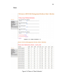
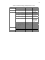
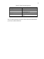
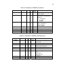
The Table 5.1 shows the information of some Sensor boards and motes.
44
Table 5.1 Sensor Boards and Motes
Crossbow
Part name
MTS101CA
MTS300CA
MTS300CB
MTS310CA
MTS310CB
MTS400CA
MTS400CB
MTS400CC
MTS420CA
MTS420CB
MTS420CC
MTS510CA
MDA100CA
MDA100CB
MDA300CA
MDA320CA
MDA500CA
Motes
supported
MICAz,MICA2,
MICA
IRIS, MICAz
MICA2, MICA
IRIS, MICAz
MICA2, MICA
IRIS, MICAz
MICA2
Sensors and Features
Light, temperature, prototyping area
Light, temperature, microphone, and buzzer
Light, temperature, microphone, buzzer, 2-axis
accelerometer, and 2-axis magnetometer
Ambient light, relative humidity, temperature, 2axis accelerometer, and barometric pressure
IRIS, MICAz
MICA2
Same as MTS400CA plus a GPS module
MICA2DOT
IRIS, MICAz
MICA2
IRIS, MICAz
MICA2
IRIS, MICAz
MICA2
MICA2DOT
Light, microphone, and 2-axis accelerometer
Light, temperature, prototyping area
Light, relative humidity, general purpose
interface for external sensors
General purpose interface for external sensors
Prototyping area
45
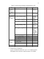
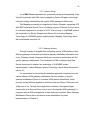
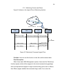
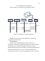
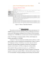
5.2. Software Platform
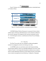
Figure 5.2 shows us the Three-tier software architecture instantiated based
on Crossbow XServe.
Figure 5.2 Three-tier architecture instantiation based on XServe
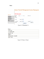
H-WSNMS Software Platform Deployment is composed of the two distinct
software layers, Client layer and Gateway layer. In above three-tier architecture,
the motes tier belongs to the hardware content we have introduced in section
5.1. In the following two sections, we will discuss the Clients Tier and Gateway
Tier respectively.
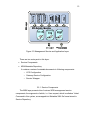
5.2.1. Client Tier
The Client Tier provides the user visualization software and graphical
interface for managing the network and retrieving sensor data.
In H-WSNMS system, we can directly acquire data through accessing
Wireless Sensor Network, which is an advantage displayed in the function “Data
Collection Function”, and manage the heterogeneous wireless sensor networks,
which is another advantage described in several familiar functions in the wireless
sensor networks management such as Monitoring, Configuration, Reprogram
46
and Data Collection and so on. In H-WSNMS, Client Tier is designed and
implemented with JSP and JavaScript Technologies.
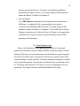
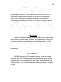
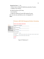
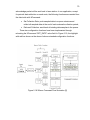
5.2.2. Specific Gateway Middleware
The Gateway Tier is an always-on facility that handles translation and
buffering of data coming from the wireless network and provides the bridge
between the wireless motes and the web-based Applications. In this Case,
XServe is a specific gateway middleware, as described in Figure 5.3, wherein
XServe and XOtap are server layer applications that can run on a PC or
Stargate.
Crossbow XServe [7] is the glue layer that connects the wireless sensor
network to enterprise or industrial networks through standard XML. Due to the
low-power and memory footprint requirements in wireless sensor networks,
communication is streamlined through message formats and network protocols.
A local database allows XServe to store and process sensor and network
information. Integration with back-end monitoring, control and management
systems delivers the full value of wireless sensor networks to enterprises and
makes the connection of the physical world with the internet a reality.
Figure 5.3 Gateway Middleware: XServe
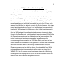
47
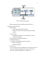
In higher level services for enterprise applications, Crossbow XServe can be
configured to parsing sensor packets into a series of name values pairs giving
richer meaning to the sensor data.
Crossbow sensor applications allow users to query state variables. This
feature is called XCommand [7]. XServe provides two interfaces for enterprise
applications to send commands to the Mote Layer using XCommand. Users can
send and receive XCommands using XServeTerm, a terminal command
application. Applications can send and receive XCommands using an XML RPC
interface. XCommand and XServeTerm are commonly and regularly used in the
Management Application Functions such as Monitoring, Configuration and Data
Connection and so on.
XServe [8] also implements the Over-the-air Programming (OTAP [8])
function, which feature allows users to reprogram any Mote within the XMesh [8]
network. OTAP allows one or more Motes to receive new programming images
from XServe (via XOtap), a server-side application via wireless communication.
The XOtap [8] application is a server side tool that works, either with XServe or
directly connected to the serial port of the XMesh Gateway, to communicate with
the XMesh network. It resides in the XServe Layer (in a remote or local server or
Stargate) of the XMesh Network landscape. Users use XOtap to download
program images to the Motes by having the application first read an IHEX image
file name and a list of Motes to download. Then the image is downloaded to each
Mote.
Appendix B represents a series of various available command parameters
referring the XServe Manual [7] and Mesh Manual [8] provided by CrossBow
MoteWorks. Appendix C makes some definitions for different functions based on
the Code Rule in Appendix A and available command parameters statement in
Appendix B. Based on these XServe features, several web-based WSNs
management functions have been designed and developed, which will be
introduced in the following section.
48
Crossbow’s XServe is used as one instance of specific WSN platform’s
gateway technology to be handled by the Unified Gateway in the H-WSNMS
architecture as shown in Figure 5.2. We demonstrate the design idea through
developing several management components: Monitoring, Reconfiguration,
Reprogram and so on. From the client tier point of view, these management
components execution details are hidden from users. In general, partial
functionality of commands required by management components can be mapped
to the Target Command already provided by XServe.
5.3. Main Functions Overview
This section will discuss the main functions of H-WSNMS based on
CrossBow XServe.
In this system, there are several main functions:
•
Monitoring: supervises the status of Wireless Sensor Networks
•
Configuration: completes Mesh Motes Configurations with XCommands
•
Reprogram: uploads the OTAP program to the motes
•
Data Collection: retrieves and displays the wireless sensor data from
HIDE own sensor data resource
The general control and status information flow in H-WSNMS system has
been illustrated in Figure 3.2, the following sections we will one by one discuss
the control and status information of functions such as Monitoring,
Reconfiguration and Reprogram and so on.
The screenshot shown in the Figure 5.4 is system user profile of H-WSNMS
WSN Management System, which provides a series of functions such as
Monitoring, Configuration, Reprogram and Data Collection and so on.
49
Figure 5.4 User Profile of H-WSNMS
50
5.3.1. Monitoring Function and Demo
Figure 5.5 shows us the Logical Flow of Monitoring function.
Figure 5.5 “Monitoring” Command Logical Flow
Function: User can use this function to view the real-time sensor data.
Flow Description:
When Users enter WSN Management system, Users send the “Monitoring”
function request, which will be wrapped to the virtual command string package,
then is interpreted and mapped to target command string and is sent to XServe,
then XServe judges whether the command string is valid; If not, return the
51
information about unavailable data to users, if yes, return the available data to
users.
Monitoring Request XML File and Mapped Result:
Table 5.2 Monitoring Request XML File and Mapped Command String
Function
Request
Node
XML
Template
Monitoring Request XML File
<?xml version="1.0" encoding="UTF-8"?>
<Monitoingreq>
<gateways>
<gateway>
<gatewayid>05</ gatewayid>
<serviceID>105110</serviceID >
<gatewayname>XServe</ gatewayname>
<device>COM5</device >
<interfaceboard>MIB520</ interfaceboard >
<baudrate >57600</baudrate >
</gateway>
<gateway>
……
</gateway>
</gateways>
</Monitoingreq >
e.g
XServe –device=COM5 –baudrate=57600
Mapped
Target
Command
String
Note
This is a General and Extendable file
Example: Available Command Parameters for XServe
(Refer XServe Users Manual [7], in which there is the detail
introduction about various Command Arguments)
XServe –device –baudrate
Function Information Description:
Monitoring Service “Monitoring” based on XServe provided by MoteWorks
platform with communication port COM5.
Service Code: 1 05 1 10
1: MoteWorks PlatformID
05: Device: GatwayID (COM port=COM5)
1: Gateway Code of XServe
10: H_Monitoring: Monitoring Service (VC Code)
52
Socket Port Code: 1 1 10
1: Platform Code or PlatformID: MoteWorks produced by Crossbow
1: Gateway Code of XServe
00: Monitoring Service (VCS Code)
1110: Socket Port
1110Req.xml: Monitoring Function XML template file name
Note: the code rules and definitions refer to the Appendix A-C.
Demo:
Figure 5.6 “Monitoring” UI
53
Figure 5.7 Demo of “Monitoring”
54
5.3.2. Configuration Function and Demo
Figure 5.8 shows us the Logical Flow of Configuration Function.
Figure 5.8 “Configuration” Command Logical Flow
Function: User can send and receive XCommand to complete the
configuration using XServeTerm.
Flow Description:
When Users enter WSN Management system, Users send one
“Configuration” function request, which will be wrapped to the virtual command
XML package, then is interpreted and mapped to the target command
string(XCommand string) and is sent to XServe, then XServe judges whether the
target command string is valid or not; If not, return the information about
unavailable data to users, if yes, return the available data to users, at the same
55
time, the updated related information about platform or WSN gateway status
automatically is stored into the H-WSNMS own database.
Configuration Request XML File and Mapped Result:
56
Table 5.3 Configuration Request XML File and Mapped Command String
Function
Request
Node
XML
Template
Configuration Request XML File
<?xml version="1.0" encoding="UTF-8"?>
<Configurationreq>
<gateways>
<gateway>
<gatewayname>XServe</ gatewayname>
<gatewayid>05</ gatewayid>
<serviceID>105121</serviceID >
<device>COM5</device >
<interfaceboard>MIB520</ interfaceboard >
<baudrate >57600</baudrate >
<xserveterm> xserveterm.exe</xserveterm>
<xcommands>
<reconfiguration>
<xcommand> get_config</xcommand>
<destinationnode>1458</destinationnode>
<update></update>
</reconfiguration>
<powermanagement>
<pmstatus></pmstatus>
<pmdestinationnode></pmdestinationnode>
</powermanagement>
</xcommands>
</gateway>
<gateway>
……
</gateway>
</gateways>
</Configurationreq >
e.g:
Mapped
Xserve –s=COM5 –b=57600
Target
Command Xserveterm> get_config 1458
String
Note
This is a General and Extendable file
Example: Available Command Parameters for XServe
(Refer XServe Users Manual [7], in which there is the detail introduction
about various XCommand Arguments)
Reconfiguration includes following xcommands
H_ReConfig_GID set_default_group <group id>
H_ReConfig_GetID get_config <destination address>
H_ReConfig _SetID set_nodeid <destination address> <new
node id>
H_ReConfig _SpRate set_rate <destination address> <new
57
rate>
H_ReConfig _CRate set_collection_rate <destination
address> <new size>
H_ReConfig _ECollect set_manual_collection <destination
address> <Flag>
Power Management includes following xcommands
H_PM_WAKEUP wake <destination address>
H_PM _SLEEP sleep <destination address>
H_PM _RESET reset <destination address>
H_PM _SHUTDOWN xserve.shutdown
Function Information Description:
Configuration Service “Set NodeID” based on XServe provided by
MoteWorks platform with communication port COM5.
Service Code: 1 05 1 22
1: MoteWorks PlatformID
05: Device: GatwayID (COM port=COM5)
1: Gateway Code of XServe
22: H_ Config_Reconfig_GetID: Set NodeID Service (VC Code)
Socket Port Code: 1 1 20
1: Platform Code or PlatformID: MoteWorks produced by Crossbow
1: Gateway Code of XServe
20: Configuration Service (VCS Code)
1120: Socket Port
1120Req.xml: Configuration Function XML file name
Note: the codes rule and definitions refer to the Appendix A~C.
58
Demo:
Figure 5.9 “Configuration” UI
Figure 5.10 Demo of “Get Config”
59
5.3.3. Reprogram Function and Demo
Figure 5.11 shows us the Logical Flow of the Reprogram Function.
Figure 5.11 “Reprogram” Command Logical Flow
Function: Query, Boot and Download program to the motes through OTAP
method with format IHEX.
•
Query: users can optionally query a node when it is running the OTAP
Image to get information about different slots.
•
Boot: reboot all chosen nodes to OTAP specified Image.
60
•
Download: specify the nodes we want to program and specify the slot.
Select the binary image of the app (main.ihex), which is implemented and
compiled by NesC language. As the OTAP progresses, you will see the
report in terms of number of pages downloaded into the flash.
Flow Description:
When Users enter WSN Management system, Users send the “Reprogram”
function request, which will be wrapped to the virtual command string XML
package, which is interpreted and mapped to the target command string, after
XOTAP receives the target command string and judges whether this mapped
command string is valid or not; If not, return the unsuccessful information to
users, if yes, return successful information, thus, users can use reprogram
function successfully to upload the programming into motes in WSNs.
Reprogram Request XML File and Mapped Result:
61
Table 5.4 Reprogram Request XML File and Mapped Command String
Function
Reprogram Request XML File
Request <?xml version="1.0" encoding="UTF-8"?>
<Reprogramreq>
Node
<gateways>
XML
<gateway>
Format
<gatewayid>05</ gatewayid>
<vcid>110161</vcid>
<COMport>COM5</COMport>
<baudrate > 57600</baudrate >
<interfaceboard>xserve</interfaceboard>
<xotap> xotap.exe</ xotap>
<commands>
<ip:port>
<cmd>-sf</cmd>
<ip> localhost</ip>
<port>9001 </port>
<ip:port>
<image_number>
<cmd>-i</cmd>
<number>2</number>
</ image_number>
<boot>
<cmd>-p</cmd>
<image_number> </image_number>
</boot>
<query>
<cmd></cmd>
</query>
<load>
<cmd></cmd>
<file>C:/main.exe.ihex</file>
</load>
<threshold>
<cmd>-v</cmd>
<vantage>2.7</vantage >
</threshold>
</commands>
<modes>
<mode>1458</mote>
</modes>
</gateway>
<gateway>
……
62
</gateway>
</gateways>
</Reprogramreq >
Mapped e.g
C:/Crossbow/cygwin/opt/MoteWorks/tools/xotap/bin.cygwin.x86/;
Target
Comman xotap.exe –I 2 -p -v 2.7 -sf localhost:9001 1458
d String
Note
This is a General and Extendable file
Available Command Parameters for XServe
(Refer XMesh Users Manual [8], in which there is the detail introduction
about various XOTAP Command Arguments)
-f <image_file> Download the file.
-i <image_number> Image number
-q Query the Mote status
-v <threshold> Download if the voltage is above the threshold
(default 2.7v)
-p <image_number> Boot the image number.
-sf <ip:port> XServe host/port (default to localhost:9001)
-c <COM port> Serial port if connected directly (eg. -c COM1)
moteID [moteID…] List the Motes to download or check status.
Function Information Description:
Reprogram Service “BOOT” based on XServe provided by MoteWorks
platform with communication port COM5.
Service Code: 1 05 1 61
1: MoteWorks PlatformID
05: Device: GatwayID (COM port=COM5)
1: Gateway Code of XServe
61: H_Repro_BOOT: Boot Service (VC Code)
Socket Port Code: 1 1 60
1: Platform Code or PlatformID: MoteWorks produced by Crossbow
1: Gateway Code of XServe
60: Reprogram Service (VCS Code)
1160: Socket Port
1160Req.xml: Reprogram Function XML file name
Note: the code rules and definitions refer to the Appendix A-C.
63
Demo:
Figure 5.12 “Reprogram” UI
Figure 5.13 Demo of “Query”
64
5.3.4. Data Collection Function and Demo
Figure 5.14 shows us the Logical Flow of WSN Data Collection Function.
Figure 5.14 “Data Collection” Command Logical Flow
Function: user retrieves the wireless sensor data from H-WSNMS wireless
sensor network data source in its own DB.
Flow Description:
Users send a WSN “Data Collection” request, system will visit the HWSNMS DB to check whether the retrieved data existed or not, if yes, display the
result to users, if no, user send a send a WSN “Data Collection” function request
again, which will be wrapped to the virtual command XML package, then is
interpreted and mapped to the target command string sent to XServe, then
65
XServe judges whether the target command string is valid or not; If not, return
the information about unavailable data to users, if yes, the data coming from
motes in WSNs synchronizes into H-WSNMS DB, then response and display the
data to users according to users’ query time requirement, i.e. Under the
satisfaction of condition, the new data will be stored into DB; at the same time,
return a “Data Notification”. After receives the “Data Notification”, the system will
re-send DB query request. Thus, users retrieve the data with on-demand
method.
66
Data Collection Request XML File and Mapped Result:
Table 5.5 Data Collection Request XML File and Mapped Command String
Function
Request
Node
XML
Format
Mapped
Target
Command
String
Note
Data Collection Request XML File
<?xml version="1.0" encoding="UTF-8"?>
< Datacollreq >
<gateways>
<gateway>
<gatewayname>XServe</ gatewayname>
<gatewayid>05</ gatewayid>
<serviceID>105100</serviceID >
<device>COM5</device >
<interfaceboard> MIB520</interfaceboard>
<baudrate >57600</baudrate >
<dbinfor>
<dbserver>149.166.32.252</dbserver>
<dbport>5432</dbport>
<dbname>IDAM</dbname>
<dbuser>tele</dbuser>
<dbpasswd>12345678</dbpasswd>
<databaseparsed>l</databaseparsed>
<xmlfile> XmlStream.xml</xmlfile>
<xmlp></xmlp>
<xmlport>9005</xmlport>
</dbinfor>
</gateway>
<gateway>
……
</gateway>
</gateways>
</Dataconnreq >
xserve –s=COM5 –b=57600 –dbserver=149.166.32.252 –
dbport=5432 –dbname=IDAM –dbuser=tele -l –
xmlfile=XmlStream.xml -xmlp –xmlport=9005
This is a General and Extendable file
Example: Available Command parameters for XServer
(Refer XServe Users Manual [7], in which there is the detail
introduction about various XCommand Arguments)
main parameters: xserve -s -b -dbserver -dbport -dbname dbuser -l -xmlfile -xmlp –xmlport
67
Function Information Description:
Data Collection Service based on XServe provided by MoteWorks platform
with communication port COM5.
Service Code: 1 05 1 00
1: MoteWorks PlatformID
05: Device: GatwayID (COM port=COM5)
1: Gateway Code of XServe
00: H_DataColl: Data Collection (VC Code)
Socket Port Code: 1 1 00
1: Platform Code or PlatformID: MoteWorks produced by Crossbow
1: Gateway Code of XServe
00: Data Collection (VCS Code)
1100: Socket Port
1100Req.xml: Data Collection Function XML file name
Note: the code rules and definitions refer to the Appendix A-C.
68
Demo:
Figure 5.15 “Data Collection” UI
Figure 5.16 Demo of “Data Collection”
69
Figure 5.17 Demo of “New Data Collection”
5.4. XServe’s Extension
This section is not the very important part in the design and implement of HWSNMS Architecture but worth mentioning, mainly considering the extension on
some specific WSN gateway middlewares such as XServe for the future system
developers, thus, H-WSNMS also can extend some new Virtual Command Sets it
needs. The following is our extension based on XServe, which displays the
flexibility and scalability of H-WSNMS.
In Figure 5.2, Three-tier architecture instantiation based on XServe, in which
we put forward to an idea of extending the command library in XServe to improve
the Configuration function , Considering no any source code, we would not
extend the .dll file about XServe parameter command set. [2] proposes an
extension method based on the XServe configuration existing available
XCommand Set. XServe provides the only entry (i.e., port 9003 [7]) for
XCommand inputs. After a mapped target command is wrapped in a packet and
injected to wireless mesh network (XMesh), it will follow the flow shown in Figure
5.18, the command for configuring sampling rate will be finally executed and the
70
acknowledge packet will be sent back to base station. In our application, except
for periodic data collection on each mote, the following functions are needed from
the client side with XCommand:
•
Set Collection Rate: push sampled data to a queue structure and
collect all sampled data at the end of each automatic collection period;
•
Enforced Collection: send back all existing data samples in the queue.
These two configuration functions have been implemented through
relocating the XCommand “SET_RATE” value field. In Figure 5.19, the highlight
with red line shows us the demo of above extended configuration functions.
Figure 5.18 XServe Command Flow Illustration [2]
71
Figure 5.19 XServe Configuration Command Extension
72
CHAPTER 6. FUTURE WORK
We provide a scheme to manage sensor networks using XML schema,
Database technologies and Socket Communication technology. The fundamental
goal of the scheme is to be able to describe sensors in a simple, compact
manner while still having the ability to represent essential details such as the
general service functions (VCS), the type of sensor platforms that can be
provided, the various parameters and application interfaces of specific gateway
middlewares that are available in WSNs. Based on these technologies, we
present a three layer framework H-WSNMS that provides the basic capabilities
for locating, managing, and querying the heterogeneous Wireless Sensor
Networks, at the same time; XServe command extension over existing command
services has finished in this system. Consequently, the design and
implementation of H-WSNMS is not only a challenge but also a chance for webbased heterogeneous Wireless Sensor Networks management system.
The underlying idea of H-WSNMS is to decouple the development of
application-specific management functions from deployed heterogeneous WSN
platforms and gateway technologies including their associated preliminary
management command services. H-WSNMS architecture not only directly
supports network management for heterogeneous WSNs, but also facilitates the
reuse of each individual WSN’s preliminary management tool as much as
possible, and at the same time, presents to users a unified interface (UG) across
multiple WSNs. We illustrated the H-WSNMS using XServe mote network
through mapping H-WSNMS’ Virtual Commands to both the existing XServe
Command Service and the newly extended XServe Command Service to realize
the flexibility and scalability of H-WSNMS. Our current H-WSNMS prototype is
73
developed in Java. We plan to extend our prototype system to include two and
more different WSN platforms and gateway technologies at the Mote layer to
further study and verify our proposed new H-WSNMS architecture. We also plan
to create more sophisticated management functionality at the MSA layer by the
composition of a sequence of Virtual Commands.
LIST OF REFERENCES
74
LIST OF REFERENCES
[1]
[2]
[3]
[4]
[5]
[6]
[7]
[8]
[9]
[10]
[11]
[12]
[13]
Chee-Yee Chong, SP Kumar., “Sensor Networks: Evolution,
Opportunities, and Challenges,” Proc. IEEE, vol.91, no. 8, 2003, pp.
1247–56.
Wei Zhao, Yao Liang, Qun Yu, Yan Sui, "H-WSNMS: A Web-Based
Heterogeneous Wireless Sensor Networks Management System
Architecture," nbis, pp.155-162, 2009 International Conference on
Network-Based Information Systems, 2009.
Akyildiz and I. Kasimoglu, “Wireless Sensor and Actor Networks:
Research Challenges,” Ad Hoc Networks J., vol. 2, no. 4, 2004, pp. 351–
67.
MicaZ DataSheet, CrossBow Technology Inc., Available online
http://www.xbow.com/Products/Product_pdf_files/Wireless_pdf/MICAZ_Da
tasheet.pdf, accessed in March, 2009.
MoteView User Manual, CrossBow Technology Inc., Available online at
http://www.xbow.com/Support/Support_pdf_files/MoteView Users
Manual.pdf, accessed in March, 2009.
MoteWorks Getting Started Guide, CrossBow Technology Inc., Available
online at http://www.xbow.com/Support/Support_pdf_files/ MoteWorks
Getting Started Guide.pdf, accessed in March, 2009.
XServe User Manual, CrossBow Technology Inc., Available online at
http://www.xbow.com/Support/Support_pdf_files/XServe Users
Manual.pdf, accessed in March, 2009.
XMesh User Manual, CrossBow Technology Inc., Available online at
http://www.xbow.com/Support/Support_pdf_files/ XMesh Users
Manual.pdf, accessed in March, 2009.
M.Turon, “Mote-View: A Sensor Network Monitoring and Management
Tool,” in Proc. of IEEE EMNET-II Workshop, May 2005, pp.11-18.
R. M. Kling, “Intel Motes: Advanced Sensor Network Platforms and
Applications,” IEEE MTT-S Int’l. Microwave Symp., 2005.
Marin-Perianu, M. Meratnia, N. Havinga, “Decentralized Enterprise
Systems: A Multiplatform Wireless Sensor Network Approach”, IEEE
WIRELESS COMMUNICATIONS, 2007, VOL 14; NUMB 6, pages 57-66
Marin-Perianu, R. S. Scholten, J. Havinga, P. J. Hartel, P. H., “Clusterbased service discovery for heterogeneous wireless sensor networks”,
INTERNATIONAL JOURNAL OF PARALLEL EMERGENT AND
DISTRIBUTED SYSTEMS, 2008, VOL 23; NUMBER 4, pages 325-346
Particle Computer, http://www.particle-computer.de
75
[14]
[15]
[16]
[17]
[18]
[19]
[20]
[21]
[22]
[23]
[24]
[25]
[26]
[27]
[28]
Y. Gsottberger et al., “Embedding Low-Cost Wireless Sensors into
Universal Plug and Play Environments,” 1st Euro. Wksp. Wireless Sensor
Networks, 2004, pp. 291–306.
V. Arnaudov. Unified Management of Heterogeneous Sensor Networks In
the Atlantis Framework. Brown U, 2005.
P. Levis, S. Madden, J. Polastre, R. Szewczyk, K. Whitehouse, A. Woo, D.
Gay, J. Hill, M. Welsh, E. Brewer, and D. Culler, “TinyOS: An Operating
System for Wireless Sensor Networks, ” In Ambient Intelligence, SpringerVerlag, 2005.
R. Tynan, D. Marsh, D. Okane, and G.M.P. Ohare, “Agents for Wireless
Sensor Network Power Management,” In Proc. of IEEE ICPPW Conf.,
June 2005.
N. Ramanathan and M. Yarvis, “A Stream-oriented Power Management
Protocol for Low Duty Cycle Sensor Network Applications,” in Proc. IEEE
EMNET-II Workshop, May 2005.
A. Boulis and M.B. Srivastava, “Node-level Energy Management for
Sensor Networks in the Presence of multiple Applications,” In Proc. IEEE
PERCOM Conf., Mar. 2003.
L.B. Ruiz, I.G. Siqueira, L.B. e Oliveira, H.C. Wong, J.M.S. Nogueira, and
A.A.F. Loureiro, “Fault Management in Event-Driven Wireless Sensor
Networks,” In Proc. ACM MSWIM Conf., Oct. 2004.
W. L. Lee, A. Datta, and R. Cardell-Oliver, “WinMS: Wireless Sensor
Network Management System, an Adaptive Policy-based management for
Wireless Sensor Networks,” Tech. Rep. UWA-CSSE-06-001, The
University of Western Australia, June 2006.
C. Hsin and M. Liu, “A Two-Phase Self-Monitoring Mechanism for
Wireless Sensor Networks,” Journal of Computer Communications special
issue on Sensor Networks, vol.29, no. 4, 2006, pp. 462-476.
T.H. Kim and S. Hong, “Sensor Network Management Protocol for StateDriven Execution Environment,” In Proc. ICUC Conf., Oct. 2003.
H. Cha and I. Jung, “RMTool: Component-Based Network Management
System for Wireless Sensor Networks” In Proc. 4th Consumer
Communications and Networking Conf., 2007, pp.614-618.
G. Tolle and D.Culler, “Design of an Application-Cooperative Management
System for Wireless Sensor Networks,” In Proc. 2th European Workshop
on Wireless Sensor Networks (EWSN), Istanbul, Turkey, January, 2005.
P.J. Marrón, A. Lachenmann, D. Minder, J. Hähner, R. Sauter, and K.
Rothermel, “TinyCubus: A Flexible and Adaptive Framework for Sensor
Networks,” In Proc. 2th Europ. Workshop on Wireless Sensor Networks,
2005, pp.278-289.
W.S. Jang, W.M. Healy, M.J. Skibniewski, “Wireless Sensor Networks as
Part of a Web-Based Building Environmental Monitoring System,”
Automation in Construction 17, 2008, pp. 729-736.
F. Yang, "Enterprise Mashup Composite Service in SOA – User Profile
Use Case," in 2008 IEEE Congress on Services - Part I, 2008, pp. 97-98.
76
[29]
[30]
[31]
[32]
[33]
[34]
[35]
[36]
[37]
[38]
[39]
[40]
J. C. Yelmo, J. M. del Alamo, R. Trapero, P. Falcarin, J. Yu, B. Carro, and
C. Baladron, "A user-centric service creation approach for Next
Generation Networks," in Innovations in NGN: Future Network and
Services, 2008. K-INGN 2008. First ITU-T Kaleidoscope Academic
Conference Geneva, Switzerland: IEEE, 2008, pp. 211-218.
D. Woods and T. Mattern, Enterprise SOA Designing IT for Business
Innovation, O’Reilly, 2006.
C. Bornhövd et al., “Integrating Smart Items with Business Processes: An
Experience Report,” Int’l. Conf. Sys. Sci., 2005.
M. Beigl et al., “Awarecon: Situation Aware Context Communication,”
UbiComp, 2003, pp. 132–39.
M. Marin-Perianu, T. J. Hofmeijer, and P. J. M. Havinga, “Implementing
Business Rules on Sensor Nodes,” 11th IEEE Int’l. Conf. Emerging
Technologies and Factory Automation, 2006, pp. 292–99.
M. Marin-Perianu and P. J. M. Havinga, “RMD: Reliable Multicast Data
Dissemination within Groups of Collaborating Objects,” Local Comp.
Networks, 2006, pp. 656–63.
F. Akyildiz, W. Su, Y. Sankarasubramaniam, and E. Cayirci. Wireless
sensor networks: a survey. Computer Networks, 38(4):393–422, March
2002.
T. Camp, J. Boleng, and V. Davies. “A survey of mobility models for ad
hoc network research”. Wireless Communications and Mobile Computing
(WCMC): Special issue on Mobile Ad Hoc Networking: Research, Trends
and Applications, 2(5):483–502, 2002.
N. Ramanathan, E. Kohler, and D. Estrin, “Towards a Debugging System
for Sensor Networks,” International Journal for Network Management,
vol.15, no. 4, 2005, pp. 223-234.
S.Bhatti, J. Carlson, H. Dai, J. Deng, J. Rose, A. Sheth, B. Shucker, C.
Gruenwald, A. Torgerson, R. Han, “Mantis OS: An Embedded
Multithreaded Operating System for Wireless Micro Sensor Platforms,”
ACM/Kluwer Mobile Networks & Applications Special Issue on Wireless
Sensor Networks, vol. 10, no.4, Aug. 2005.
D. Gay, P. Levis, R.V. Behren, M. Welsh, E. Brewer, D. Culler, “The NesC
Language: A Holistic Approach to Networked Embedded Systems,” In
Proc. ACM SIGPLAN Conf. on Programming Language Design and
Implementation, June, 2003.
Donald Brutzman, Michael Zyda, J. Mark Pullen and Katherine L. Morse:
Extensible Modeling and Simulation Framework (XMSF): Challenges for
Web-Based Modeling and Simulation, Findings and Recommendations
Report of the XMSF Technical Challenges Workshop and Strategic
Opportunities Symposium, October 2002.
APPENDICES
77
Appendix A.
Table A.1 Parameters Definition
Parameters
Platform Name
Platform ID (extendable)
Gateway Name
Gateway ID (extendable)
Gateway Code (extendable)
Communication Port
Information send by users
ReqString XML
ServiceID (extendable)
VCS Category
SubVCS Category
VCS Code
ReqString XML
(extendable)
Socket IP
Socket Port (PortID)
(extendable)
Definition
Wireless Sensor Platform Name
Particle (produced by Particle Computer)
μNode (produced by Ambient Systems)
Sindrion (produced by Infineon Technologies)
MoteWorks (produced by CrossBow)
PlatformNo. N: 1~9
e.g XServe
XX: 01~99
Y:1~9
COMx+1
Command Information from Users
Stored in Service Repository
Be used to describe the command service
NXXY00~NXXY09 for H-DataColl VCS
NXXY10~NXXY19 for H_Monitoring VCS
NXXY20 for H_Config VCS
NXXY21~NXXY39 for H_Config_Reconfig subVCS
NXXY40~NXXY59 for H_Config_PM subVCS
NXXY60~NXXY69 for H_Repro VCS
NXXY70~ for H_Others VCS
H_DataColl Data Collection
H_Monitoring Sernsor and gateway Information
Monitoring
H_Config Sernsor and gateway information
configuration
H_Repro Reprogram
H_Config:
1. H_Config_Reconfig
2. H_Config_PM
00: H_DataColl
10: H_Monitoring
20: H_Config
60: H_Repro
70: H_Others
1. Stored in Serviced Repository
2. Be parsed to Target Command String to send to
Mote layer
3. XML file name based on Socket Port No.
e.g: XML file for Data Collection
NY00Req.xml
Socket Server IP address: xxx.xxx.xxx.xxx
NY00 for H_DataColl
NY10 for H_Monitoring
NY20 for H_Config
NY60 for H_Repro
78
Table A.2 Command Category and Specification of VCS
VCS Category
H_DataColl
VC
H_DataColl
Command
H_Monitoring
H_Monitoring
H_Config
H_Config_Reconfig_SpRate
SET_RATE
H_ Config_Reconfig_NID
H_ Config_Reconfig_GID
SET_NODEID
SET_GROUP
H_ Config_Reconfig_CRate
H_Config_Reconfig_ECollect
H_Repro
H_Others
……
H_Config_PM_RESET
H_Config_PM_SLEEP
H_Config_PM_WAKEUP
……
H_Repro_Boot
H_Repro_Query
H_Repro_Load
……
……
……
RESET
SLEEP
WAKEUP
……
……
Function
Data connection
Monitoring
sensor data
Set new
Sampling Rate
Assign Node ID
Assign a Node
to new group
Set collection
rate
Immediately
perform a data
collection from
WSN and store
it to DB
……
……
……
79
Appendix B.
Table B.1 XServe Command Line Parameters
XServe Command Line Parameters
Usage: xserve <-?|r|a|p|c|xr|xp|xc|dbxmlr|xmlp|xmlc|v|alert|m>
<-l=tablename>
<-dbserver=servername> <-dbport=portnum>
<-dbname=database name> <-dbuser=username>
<-dbpasswd=password>
<-h=path,hostname,portnum,config_file>
<-m=com,baud,protocol,slaveaddress,defaultregistervaluesas>
<-xmlfile=filename> <-xmlport=portnum>
[<-sf=hostname:port> | <-fsf=hostname:port> | <-device=dev>]
<-port=num> <-baud=num> <-platform=plt>
<-debug=level>
<-configfiles=filename:filename:>
<-loadparsers=filename:filename:...>
<-loaddatasinks=filename:filename:...>
<-heartbeat=<num missed>
-? = display help [help]
-r = raw display of tos packets [raw]
-a = ascii display of tos packets [ascii]
-p = parsed display of tos packets [parsed]
-c = converted display of tos packets [conveted]
-xr = raw tos packets xported to file [export raw]
-xp = parsed tos packets exported to file [export parsed]
-xc = converted tos packets exported to file [export converted]
-db = parsed tos packets exported to db [database parsed]
-dbserver = database server name (default=localhost)
-dbport = database server port number (default=5432)
-dbname = database name (default=MoteView db)
-dbuser = database user (default=MoteView user)
-dbpasswd = database user password (default=MoteView user password)
-l = parsed tos packets exported to db
(deprecated) [database parsed]
-xmlr = raw tos packets exported to xml [xml raw]
-xmlp = parsed tos packets exported to xml [xml parsed]
-xmlc = converted tos packets exported to xml [xml converted]
-xmlfile = file name to store exported xml (default=screen)
-xmlport = port number to start the xml server
-v = show version of all modules
-h = display data through web server
-m = export data using modbus
-port = set server port <default = 9001>
-sf = connect to unframed serial forwarder
-fsf = connect to framed serial forwarder
-device = connect to serial device <default = /dev/ttyS0>
-baud = set serial baud rate <default = 57600>
-platform = set platform. <default = mica2>
values=mica2dot|mica2|mica|telos|micaz
-debug = set debug level. <default = DBG_WARNING>
-alert = alert when data values are above/below specified ranges
-daemon = run in daemon mode
80
-nomonitor = run without a system monitor
-configfiles = load xml configuration files.
-loadparsers = load only the listed parsers files.
(default=all files are loaded)
-loaddatasinks = load only the listed datasinks files.
(default=all files are loaded)
-heartbeat = turn on the heartbeat monitor and reset after <num missed>
-convZto2 = convert incoming network packets from micaZ headers to
mica2 headers and vice versa
-conv2toZ = convert incoming network packets from mica2 headers to
micaZ headers and vice versa
Table B.2 XServe Configuration Command Line Parameters
XServe Configuration Command Line Parameters
Usage: xserve <-?|r|a|p|c|xr|xp|xc|dbxmlr|xmlp|xmlc|v|alert|m>
-device = connect to serial device <default = /dev/ttyS0>
-baud = set serial baud rate <default = 57600>
-device = connect to serial device <default = /dev/ttyS0>
Table B.3 XServeTerm Line Parameters
XServeTerm Line Parameters
Usage: xcommand <-?> <-server=host:port> <-network=xmesh|xsensor>
-? = display help [help]
-server = xserve command port [host:port]
-network = network type (default = xmesh) [xmesh|xsensor]
-seq = starting sequence number (default=100)
-group = network group id (default=145)
81
Table B.4 XServeTerm Available Parameters
XServeTerm Available Parameters
Available Commands:
set_timeout <timeout ms>
set_starting_sequence <sequence number>
set_default_group <group id>
get_config <destination address>
set_rate <destination address> <new rate>
set_nodeid <destination address> <new node id>
set_groupid <destination address> <new group id>
set_rfchannel <destination address> <new rf channel>
set_rfpower <destination address> <new rfpower>
sleep <destination address>
wake <destination address>
reset <destination address>
xserve.shutdown
actuate <destination address> <device> <state>
device ids states
------------------------------------green led 0 off 0
yellow led 1 on 1
red led 2 toggle 2
all leds 3
sounder 4
relay1 5
relay2 6
relay3 7
82
Table B.5 XCommand Categories and Description
Command
Category
Power
Management
Basic Update
Rate
Command
Arguments
RESET
SLEEP
WAKEUP
SET_RATE
Mote
Configuration
Parameter
Settings
• GET_CONFIG
• SET_NODEID
• SET_GROUP
• SET_RF_POWER
• SET_RF_CHANNEL
Actuation
ACTUATE
• SET_LED
• SET_SOUND
• SET_RELAY
Description
To reset the sleep and
wakeup time.
To get or set the update
rate. The set_rate
command changes the
data acquisition duty
cycle of the mote. The
first argument is the new
timer interval in
milliseconds.
This set of commands
allows you to get and set
radio frequency and
power, including
channel.
0=OFF, 1=ON,
2=TOGGLE
0=OFF, 1=ON
0=OFF, 1=ON
This set of commands
actuates each individual
LED with the option to
operate on all three
LEDs.
This command turns the
sounder off or on.
This command turns the
relays on
Table B.6 XServe Reprogram Line Parameters
XServe Reprogram Line Parameters
Usage: xserve <-?|r|a|p|c|xr|xp|xc|dbxmlr|xmlp|xmlc|v|alert|m>
-? = display help [help]
-p = parsed display of tos packets [parsed]
-c = converted display of tos packets [conveted]
-v = show version of all modules
-port = set server port <default = 9001>
-sf = connect to unframed serial forwarder
-fsf = connect to framed serial forwarder
-device = connect to serial device <default = /dev/ttyS0>
-baud = set serial baud rate <default = 57600>
-platform = set platform. <default = mica2>
values=mica2dot|mica2|mica|telos|micaz
83
Table B.7 XOtap Command Arguments
Command Interface
-f <image_file>
-i <image_number>
-q
-v <threshold>
-p <image_number>
-sf <ip:port>
-c <COM port>
moteID [moteID…]
Description
Download the file
Image number
Query the Mote status
Download if the voltage is above the
threshold (default 2.7v)
Boot the image number
XServe host/port (default to localhost:9001)
Serial port if connected directly (eg. -c
COM1)
List the Motes to download or check status
Note: The above parameters referring the XServe Manual and Mesh Manual
provided by CrossBow MoteWorks.
84
Appendix C.
Table C.1 Monitoring ServiceID Definition
H_Monitoring VCS (NXXY10: extendable)
ServiceID
Description
105110
H_Monitoring: Monitoring WSN
xserve –s=COM5 –b=57600
……
……
Table C.2 Configuration ServiceID Definition
H_Config_ReConfig VCS (NXXY20~ NXXY39: extendable)
ServiceID
Description
105121
H_ Config_Reconfig_GID set_default_group
<group id>
105122
H_ Config_Reconfig_GetID get_config
<destination address>
105123
H_ Config_Reconfig_SetNID set_nodeid
<destination address> <new node id>
105124
H_ Config_Reconfig_SpRate set_rate
<destination address> <new rate>
105125
H_ Config_Reconfig_CRate
set_collection_rate <destination address>
<new size>
105126
H_ Config_Reconfig_ECollect
set_manual_collection <destination address>
<Flag>
……
……
H_Config_PM VCS (NXXY40~ NXXY59: extendable)
ServiceID
Description
105140
H_Config_PM_WAKEUP wake <destination
address>
105141
H_Config_PM_SLEEP sleep <destination
address>
105142
H_Config_PM_RESET reset <destination
address>
105143
H_Config_PM_SHUTDOWN xserve.shutdown
……
……
85
Table C.3 Reprogram ServiceID Definition
ServiceID
105161
105162
105163
……
H_Repro VCS (NXXY60~69: extendable)
Description
H_Repro_BOOT
C:/Crossbow/cygwin/opt/MoteWorks/tools/xotap/bin.cygwin.x86/;xotap.exe
–I 2 -p -v 2.7 -sf localhost:9001 1458
H_Repro_QUERY
C:/Crossbow/cygwin/opt/MoteWorks/tools/xotap/bin.cygwin.x86/;xotap.exe
–I 2 -q -v 2.7 -sf localhost:9001 1458
H_Repro_LOAD
C:/Crossbow/cygwin/opt/MoteWorks/tools/xotap/bin.cygwin.x86/;xotap.exe
–I 2 -f C:/main.exe.ihex -v 2.7 -sf localhost:9001 1458
……
Table C.4 Data Collection ServiceID Definition
ServiceID
105100
……
H_DataColl VCS (NXXY00: extendable)
Description
H_DataColl
xserve –s=COM5 –b=57600 –dbserver=149.166.32.252 –dbport=5432 –
dbname=HWSNMS –dbuser=tele -l –xmlfile=XmlStream.xml -xmlp –
xmlport=9005
……
Note: The above definitions referring the parameters provided by XServe in
MoteWorks platform.
86
Appendix D.
Table D.1 DataTable H-WSNMS_ServicInfor
Parameter name
Type
ServiceID
nVarChar
PlatformName
PlatformID
nVarChar
nVarChar
gatewayName
gatewayID
gatewayCode
nVarChar
VarChar
VarChar
ServiceCategory
nVarChar
CategoryFirstNu
m
nVarChar
ServiceCode
nVarChar
XMLfileName
SocketPort
Reserved1
Reserved2
nVarChar
nVarChar
nVarChar
nVarChar
Size
Key
Default
Value
Yes
Statement
PlatformID+gatewayID+gat
ewaycode+ VCcode
e.g MoteWorks
Unique indentified number
for Wireless Sensor
Platform
e.g XServe
X0 X:1~9
Type number of gateway
e.g XServe=1
Classified into monitoring,
configuration,
reprogramming and so on
e..g H_DataConn
H_Config
H_Repro
00 for H_DataConn
10 for H_Monitoring
20 for H_Config
60 for H_Repro
Category number of
ServiceID
XML file Name
Socket Port
Null
Null
Table D.2 Datatable H-WSNMS_PlatformState
Parameter
name
PlatformName
Type
nVarChar
PlatformID
nVarChar
GatewayName
nVarChar
GatewayID
nVarChar
PlatformState
nVarChar
Reserved1
Reserved2
nVarChar
nVarChar
Size
Key
Default
Value
Yes
Statement
Wireless Sensor Platform
Unique indentified number
for Wireless Sensor
Platform
Gateway Name
e.g XServe
COM port number
0: set up
1: shut down
Null
Null
87
Table D.3 Datatable H-WSNMS_SocketInfor
Parameter name
Type
Size
ServiceID
nVarChar
ServiceCategory
nVarChar
CategoryFirstNum
nVarChar
SocektIP
nVarChar
SocektPort
nVarChar
Reserved1
Reserved2
nVarChar
nVarChar
Key
Default
Value
Yes
Statement
PlatformID+gatewayID+gateway
code+ VCcode
Classified into monitoring,
configuration, reprogramming
and so on
e..g H_DataConn
H_Config
H_Repro
00 for H_DataConn
10 for H_Monitoring
20 for H_Config
60 for H_Repro
xxx.xxx.xxx
Socket port number
Null
Null
Table D.4 Datatable H-WSNMS_GatewayConfig
Parameter
name
ServiceID
Type
nVarChar
PlatformName
nVarChar
PlatformID
nVarChar
OSplatform
nVarChar
Size
Key
Default
Value
Yes
Statement
PlatformID+gatewayID+gatewaycod
e+ VCcode
Wireless Sensor Platform
Unique indentified number for
Wireless Sensor Platform
Operation System
EfilePath
Executable file Path
Efile
nVarChar
Reserved1
Reserved2
nVarChar
nVarChar
Executable file
e.g
XServe.exe
XServeterm.exe
XToap.exe
Null
Null
88
Appendix E.
Figure E.1 the Whole Design of H-WSNMS