1
INSTRUCTION MANUAL
INTERACTIVE VISUAL COMMUNICATOR
VC-H1
KENWOOD CORPORATION
© B62-0974-10 (K)
09 08 07 06 05 04 03 02 01
NOTICES TO THE USER
One or more of the following statements may be
applicable:
FCC WARNING
This equipment generates or uses radio frequency energy. Changes
or modifications to this equipment may cause harmful interference
unless the modifications are expressly approved in the instruction
manual. The user could lose the authority to operate this equipment if
an unauthorized change or modification is made.
INFORMATION TO THE DIGITAL DEVICE USER REQUIRED BY
THE FCC
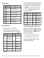
This equipment has been tested and found to comply with the limits
for a Class B digital device, pursuant to Part 15 of the FCC Rules.
These limits are designed to provide reasonable protection against
harmful interference in a residential installation.
This equipment generates, uses and can generate radio frequency
energy and, if not installed and used in accordance with the
instructions, may cause harmful interference to radio communications.
However, there is no guarantee that the interference will not occur in a
particular installation. If this equipment does cause harmful
interference to radio or television reception, which can be determined
by turning the equipment off and on, the user is encouraged to try to
correct the interference by one or more of the following measures:
• Reorient or relocate the receiving antenna.
• Increase the separation between the equipment and receiver.
• Connect the equipment to an outlet on a circuit different from that to
which the receiver is connected.
• Consult the dealer for technical assistance.
THANK YOU!
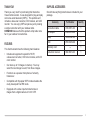
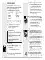
SUPPLIED ACCESSORIES
Thank you very much for purchasing this Interactive
Visual Communicator. It was designed for plug-and-play
color slow-scan television (SSTV). This portable unit
includes a slow-scan converter, CCD camera, and LCD
monitor. You can enjoy SSTV anywhere just by making
a single connection with your amateur radio.
KENWOOD believes that this product will provide more
fun in your outdoor ham activities.
Check that everything listed below is included in your
package.
FEATURES
This Communicator has the following main features:
•
Includes all equipment required for SSTV;
a slow-scan converter, CCD color camera, and LCD
color monitor.
•
Can store up to 10 images in memory. You may
select the best image to send, from those images.
•
Functions as a speaker microphone of a handy
transceiver.
•
Compatible with 8 popular SSTV modes besides the
newly developed Fast FM mode.
•
Equipped with a video input terminal to take in
images from a digital camera or 8 mm VTR.
Accessory
Part Number
Quantity
Connection cable
E30-3301-XX
1
AC adapter
W08-0559-XX
1
Strap
J69-0344-XX
1
Cloth
W01-0439-XX
1
—
1
B62-0974-XX
1
Warranty card
Instruction manual
i
CONTENTS
PRECAUTIONS ......................................................... 1
BATTERY SAVER .................................................... 11
CONVENTIONS FOLLOWED IN THIS MANUAL ....... 1
SUPERIMPOSING A CALL SIGN ............................ 12
GETTING ACQUAINTED
2
AUTO TRANSMIT ................................................... 13
ORIENTATION ........................................................... 2
AF MUTING ............................................................. 13
CONNECTOR DESCRIPTIONS ................................ 2
DISPLAY CONTRAST CHANGE ............................. 13
PREPARATION
3
14
INSTALLING ALKALINE BATTERIES ........................ 3
GENERAL INFORMATION ...................................... 14
ATTACHING THE STRAP .......................................... 4
SERVICE ................................................................. 14
CONNECTING THE AC ADAPTER ........................... 4
SERVICE NOTE ...................................................... 14
CONNECTION WITH A HANDY TRANSCEIVER ...... 5
CLEANING .............................................................. 14
REMOVING/ REINSTALLING THE CAMERA UNIT ... 5
TROUBLESHOOTING ............................................. 15
QUICK USE
6
OPERATING BASICS
7
VC-H1 DATA PORT PIN FUNCTIONS .................... 16
SWITCHING POWER ON/OFF ................................. 7
CONNECTION DIAGRAM WITH TS-570
OR TS-870 .............................................................. 16
SELECTING A SSTV MODE ...................................... 7
CAPTURING IMAGES ............................................... 8
TRANSMITTING IMAGES ......................................... 9
RECEIVING IMAGES .............................................. 10
AUXILIARY FUNCTIONS
11
MEMORY PROTECTION ........................................ 11
MEMORY RESET .................................................... 11
ii
MAINTENANCE
APPENDIX
16
COMPUTER CONTROL .......................................... 17
SPECIFICATIONS
19
PRECAUTIONS
CONVENTIONS FOLLOWED IN THIS MANUAL
Please observe the following precautions to prevent fire,
personal injury, or product damage:
The writing conventions described below have been
followed to simplify instructions and avoid unnecessary
repetition.
•
•
•
Never open this product. You will get an electric
shock if you touch the circuit on which high voltage is
applied.
Do not install batteries in a hazardous environment
where sparks could cause an explosion.
Never discard old batteries in fire because extremely
high temperatures can cause batteries to explode.
•
Do not modify this product unless instructed by
KENWOOD documentation.
•
Do not apply excessive force to the monitor display.
•
Do not expose this product to long periods of direct
sunlight nor place it close to heating appliances.
•
Do not place this product in excessively dusty areas,
humid areas, wet areas, nor on unstable surfaces.
•
If an abnormal odor or smoke is detected coming
from this product, turn OFF the power immediately
and remove the batteries from the product. When
using AC power, also remove the AC adapter from an
AC outlet. Contact your authorized KENWOOD
dealer, customer service, or service station.
Instruction
What to Do
Press [KEY].
Press and release KEY.
Press [KEY1]+[KEY2].
Press and hold KEY1, then
press KEY2.
Press
[KEY]+ POWER ON.
With VC-H1 power OFF,
press and hold KEY, then
slide the PWR switch upward.
With VC-H1 power OFF,
Press [KEY1]+[KEY2]+ press and hold KEY1 and
POWER ON.
KEY2, then slide the PWR
switch upward.
Note: Pressing the same key again immediately after pressing [KEY]+
POWER ON causes the setting to be changed back.
1
GETTING ACQUAINTED
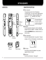
ORIENTATION
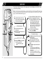
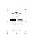
CONNECTOR DESCRIPTIONS
q Video input jack
This jack accepts a 3.5 mm (1/8") diameter,
3-conductor plug. You may connect a digital camera
or 8 mm VTR to take in images (acceptable video
signals: 75 Ω, 1 VP-P (140 IRE) ±15%, NTSC).
CCD
camera
1
COM jack
LCD
monitor
Video
output jack
DC IN jack
Speaker/
microphone
Ground
No Connection
Video
signal
1
When connecting a device
other than the provided
camera unit, using this
conductor could cause the
device to be damaged.
w COM jack
Connect a personal computer in which a dedicated
program has been installed. For details, contact your
authorized KENWOOD dealer, customer service, or
service center.
e Video output jack
Connect an external monitor, if you prefer. This jack
accepts a 2.5 mm (1/10") diameter, 2-conductor plug.
Ground Video
signal
DATA port
Video input jack
r DC IN jack
Connect the provided AC adapter to use power
supplied from an AC outlet.
t DATA port
Connect your transceiver. See page 5.
2
PREPARATION
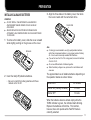
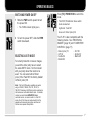
INSTALLING ALKALINE BATTERIES
WARNING!
◆ DO NOT INSTALL THE BATTERIES IN A HAZARDOUS
ENVIRONMENT WHERE SPARKS COULD CAUSE AN
EXPLOSION.
◆ NEVER DISCARD OLD BATTERIES IN FIRE BECAUSE
EXTREMELY HIGH TEMPERATURES CAN CAUSE BATTERIES
TO EXPLODE.
3 Align the three tabs on the battery cover, then slide
the cover inward until the center tab clicks.
Center tab
1 To remove the battery cover, slide the cover outward
while slightly pushing on the grooves on the cover.
Grooves
2 Insert four AA (LR6) alkaline batteries.
• Be sure to match the battery polarities with those
marked on the VC-H1.
Note:
◆ It is strongly recommended to use high quality alkaline batteries
rather than manganese batteries, to enjoy longer periods of battery
life. Do not use commercially available NiCd batteries.
◆ If you will not use the VC-H1 for a long period, remove the batteries
from the VC-H1.
◆ Do not use different kinds of batteries together.
◆ When the battery voltage is low, replace all four old batteries with
new ones.
The approximate lives of alkaline batteries depending on
the operation status are shown below:
Camera ON
50 minutes
Monitor ON (memory recalled)
2 hours
Monitor OFF
6 hours
When the batteries become almost empty while the
TX/RX indicator is green, the indicator starts blinking.
Replace the batteries at that time. This function,
however, does not operate while Fast FM mode is
currently selected.
3
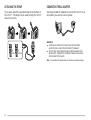
ATTACHING THE STRAP
CONNECTING THE AC ADAPTER
If you want, attach the provided strap to the bottom of
the VC-H1. The strap can be used to hang the VC-H1
around your neck.
Use the provided AC adapter to connect the VC-H1 to an
AC outlet if you want to use AC power.
Lock
Unlock
WARNING!
◆ USING AN AC ADAPTER OTHER THAN THE PROVIDED
ADAPTER CAN CAUSE FIRE OR PRODUCT DAMAGE.
◆ DO NOT USE AN EXTENSION CABLE UNLESS ABSOLUTELY
NECESSARY. IMPROPER EXTENSION CABLES CAN CAUSE
FIRE OR ELECTRIC SHOCK.
Note: The provided AC adapter does not function as a battery charger.
4
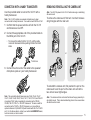
CONNECTION WITH A HANDY TRANSCEIVER
REMOVING/ REINSTALLING THE CAMERA UNIT
Use the provided cable to connect the VC-H1 with a
handy transceiver.
Note: Turn OFF the power to the VC-H1 before removing or reinstalling
the camera unit.
Note: The VC-H1 functions as a speaker microphone only when
connected with a handy transceiver. You need not switch ON the VC-H1.
To remove the camera unit, first turn it so that it crosses
at right angles with the main unit.
1 Confirm that the power switches of both the VC-H1
and transceiver are OFF.
2 Connect the appropriate end of the provided cable to
the DATA port of the VC-H1.
• To remove the cable from the VC-H1, pull the cable
connector downward while pushing its tabs from both
sides.
or
To remove
3 Connect the other end of the cable to the speaker/
microphone jacks on your handy transceiver.
To reinstall the camera unit, first position the port on the
camera unit over the port on the main unit so that the
two units cross at right angles.
Note: The compatible handy transceivers are TH-26, TH-46, TH-27,
TH-47, TH-28, TH-48, TH-22, TH-42, TH-77, TH-78, TH-79, and TH-G71.
An optional PG-4T cable is available for connecting with a TM-255,
TM-455, TM-733, TM-V7, or TM-G707 transceiver. To make a cable for
connecting with a TS-570 or TS-870 transceiver, you may obtain an
optional connector kit (E59-0407-08) which mates with the VC-H1 DATA
port. For the above options, contact your authorized KENWOOD dealer,
customer service, or service center.
Note: The camera unit has a structure that allows the plug assembly to
be slightly moved. This is aimed at absorbing stress to be caused when
the camera unit is turned.
5
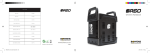
QUICK USE
If you have a handy transceiver, the steps given here will allow you to try SSTV with
your friend right away.
Note: To correctly receive or transmit images, you and your friend have to select the same SSTV mode. If you
prefer using a mode other than Robot (color) 36 which is the factory default, see “SELECTING A SSTV MODE”
{page 7} and “RECEIVING IMAGES” {page 10}.
TIVE
RAC
INTE
N
ATIO
UNIC
OMM
AL C
VISU
X
TX/R
OR
IVE ICAT
RACT MMUN
INTE AL CO
VISU 1
VC-H
Confirm that the VC-H1 has
been correctly connected with
the transceiver {page 5}.
S
On the transceiver:
PTT
LD
HO
FA
ON
ST
FM
RX
MR
Turn ON the power to the
transceiver.
Select the same frequency as
the other party.
TX
On the VC-H1:
Slide the PWR switch upward
to turn the power ON.
• The TX/RX indicator lights
green.
To receive and store an image in memory:
When an image signal is received,
the image is displayed on the monitor.
• The TX/RX indicator lights orange
while an image is being received.
• If the TX/RX indicator is green even
when the monitor is deactivated by the
Battery Saver {page 11}, the VC-H1
can receive an image.
To store the received image in
memory, press [MR].
To transmit an image:
Press [S] to activate both the camera
and LCD monitor.
• The TX/RX indicator goes out.
While looking at the LCD monitor,
turn and focus the camera onto an
object.
Press [TX] to capture and transmit
the image.
• You need not press the PTT switch.
• The TX/RX indicator lights red during
transmission.
• A horizontal line appears and slowly
moves downward to show the progress
of transmission.
6
OPERATING BASICS
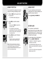
SWITCHING POWER ON/OFF
1 Slide the PWR switch upward to turn
the power ON.
Press [TX]+ POWER ON to switch the
mode.
• The FAST FM indicator shows which
mode is selected.
• The TX/RX indicator lights green.
Lights red: Fast FM
Goes out: Robot (color) 36
2 To turn the power OFF, slide the PWR
switch downward.
SELECTING A SSTV MODE
To correctly transmit or receive images,
you and the other party have to select
the same SSTV mode. So first consult
with your party about the mode to be
used. You can select either Robot
(color) 36 or Fast FM; the factory default
is Robot (color) 36.
The VC-H1 is also compatible with the
following modes. See “RECEIVING
IMAGES” {page 10} and “COMPUTER
CONTROL” {page 17}.
•
•
•
•
Robot (color) 72
AVT 94
Scottie S2
Martin M2
• AVT 90
• Scottie S1
• Martin M1
Note: The Fast FM mode is available only when
using a TM-255, TM-455, TM-733, TM-V7, or
TM-G707 transceiver; 9600 bps must be selected on
the transceiver as the data transfer rate. For details,
contact your authorized KENWOOD dealer,
customer service, or service center. In Fast FM
mode, the VC-H1 does not output audio from the
speaker while receiving an image, and does not
function as a speaker microphone.
7
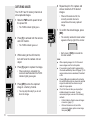
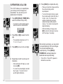
CAPTURING IMAGES
The VC-H1 has 10 memory channels to
store captured images.
1 Slide the PWR switch upward to turn
the power ON.
• The TX/RX indicator lights green.
6 Repeat step 2 to 5 to capture and
store a maximum of 10 desired
images.
• When all channels are full, the
currently selected channel is
overwritten with a newly captured
image.
7 To confirm the stored images, press
[MR].
2 Press [S] to activate both the camera
and LCD monitor.
• The currently selected channel number
appears at the top right of the monitor.
• The TX/RX indicator goes out.
3 While looking at the LCD monitor,
turn and focus the camera onto an
object.
4 Press [S] again to capture the image.
• When capturing is completed, the
camera is deactivated and the TX/RX
indicator lights green again.
5 Press [MR] to store the captured
image in a memory channel.
• You may skip this step if you do not
store the image.
8
• Each press of [MR] increments the
channel number.
Note:
◆ While capturing images, the VC-H1 does not
receive images sent from other parties.
◆ If no operation is performed for approximately
30 seconds with Battery Saver ON {page 11}, the
camera and monitor are deactivated; the default
is ON.
◆ Pressing [S] again immediately after activating
the camera and monitor may cause the captured
image to be distorted; the camera is not yet
ready for image capture.
◆ The VC-H1 does not allow you to specify an
individual image to be erased. To erase
unnecessary images, use one of the following
methods:
• Perform Memory Reset to erase all images
at one time {page 11}.
• When all channels are full, recall the
unnecessary image, capture a new image,
then press [MR].
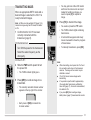
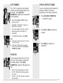
TRANSMITTING IMAGES
When an appropriate SSTV mode and a
desired image is selected, the VC-H1 is
ready to transmit images.
Note: AF Mute must be switched OFF {page 13} to
transmit an image using Fast FM mode; the default
is ON.
1 Confirm that the VC-H1 has been
correctly connected with the
transceiver {page 5}.
• You may just look at the LCD monitor
and focus the camera onto an object
instead of recalling an image; you
need not press [S] to capture an
image.
6 Press [TX] to transmit the image.
• You need not press the PTT switch.
• The TX/RX indicator lights red during
transmission.
On the transceiver:
• A horizontal line appears and slowly
moves downward to show the progress
of transmission.
2 Turn ON the power to the transceiver.
• To interrupt transmission, press [RX].
3 Select the same frequency as the
other party.
On the VC-H1:
4 Slide the PWR switch upward to turn
the power ON.
• The TX/RX indicator lights green.
5 Press [MR] to recall an image to be
transmitted.
• The currently selected channel number
appears at the top right of the monitor.
Note:
◆ While transmitting, do not place the VC-H1 and
the connection cable close to the transceiver
antenna. The image on the monitor may be
distorted or erased.
◆ The VC-H1 cannot receive images while
transmitting.
◆ If no operation is performed for approximately
30 seconds after transmission, with Battery
Saver ON {page 11}, the monitor is deactivated;
the default is ON.
◆ If you press [RX] after recalling an image,
Battery Saver {page 11} deactivates the monitor.
• Each press of [MR] increments the
channel number.
9
7 When an image signal is received,
the image is displayed on the monitor.
RECEIVING IMAGES
When the VC-H1 receives an image
signal, it automatically identifies and sets
the appropriate SSTV mode. The
compatible modes are listed below:
•
•
•
•
•
Robot (color) 36
AVT 90
Scottie S1
Martin M1
Fast FM
•
•
•
•
• The TX/RX indicator lights orange
while an image is being received.
• If the TX/RX indicator is green even
when the monitor is deactivated by the
Battery Saver {page 11}, the VC-H1
can receive an image.
Robot (color) 72
AVT 94
Scottie S2
Martin M2
8 To store the received image in an
empty memory channel, press [MR].
• If the size of the received image is too
large to be stored in one channel, the
next channel is also used.
• When all channels are full, the
currently selected channel is
overwritten with a received image.
Note: AF Mute must be switched OFF {page 13} to
receive an image transmitted using Fast FM mode;
the default is ON.
1 Confirm that the VC-H1 has been
correctly connected with the
transceiver {page 5}.
On the transceiver:
2 Turn ON the power to the transceiver.
3 Select the same frequency as the
other party.
4 Adjust the volume control to a
medium level.
On the VC-H1:
5 Slide the PWR switch upward to turn
the power ON.
• The TX/RX indicator lights green.
VOL
6 Tell the other party that you are ready
to receive an image.
10
ENC
Note:
◆ When you fail to receive the first portion of an
image signal in a mode other than AVT 90, AVT
94, and Fast FM, pressing [RX] allows you to
receive the remaining portion. However,
because of possible insufficient synchronization,
the VC-H1 could show an inappropriate color of
an image, or fail to receive an image even if the
TX/RX indicator lights orange.
◆ The automatically identified SSTV mode is used
for your next transmission unless the mode is
manually changed. If the identified mode is
neither Robot (color) 36 nor Fast FM, switching
OFF the VC-H1 causes it to restore the
previously selected mode; Robot (color) 36 or
Fast FM.
◆ If using a handy transceiver, switch OFF Battery
Saver. When Battery Saver is ON, the
transceiver may fail to receive an image.
◆ If using a TH-G71 transceiver, increasing the
audio volume beyond a certain amount may
cause the transceiver to fail to receive an image.
Select the volume in the range shown to the left.
AUXILIARY FUNCTIONS
MEMORY PROTECTION
MEMORY RESET
You can protect the captured or received
images from being accidentally erased.
You may sometimes want to reset all
settings back to the factory defaults and
clear the memory channels.
1 Slide the PWR switch upward to turn
the power ON.
Press [S]+[HOLD]+ POWER ON.
• The TX/RX indicator lights green.
2 Press [MR] to recall the desired
image.
• Each press of [MR] increments the
channel number.
• If no operation is performed for
approximately 30 seconds with Battery
Saver ON, the monitor is deactivated;
the default is ON.
3 Press [HOLD] to switch Protection
ON (or OFF).
• When the channel is protected, its
number on the monitor turns red.
Note: When the protected memory channel is
currently selected, the VC-H1 may still capture or
receive an image to display on the monitor.
However, the protected channel will not be used to
store the newly displayed image.
BATTERY SAVER
If no operation is performed for
approximately 30 seconds, Battery Saver
automatically turns OFF the power to the
camera and monitor units. Pressing [S]
activates the units again.
To switch Battery Saver ON (default) or
OFF, press [MR]+ POWER ON.
• “SAVE-ON” or “SAVE-OFF” appears to
indicate the new status.
• The TX/RX indicator lights green when
Battery Saver deactivates the camera and
monitor.
• The VC-H1 can still receive images when
Battery Saver is ON.
11
SUPERIMPOSING A CALL SIGN
The VC-H1 allows you to superimpose
your call sign onto an image to be
transmitted. You can enter up to 8
alphanumeric characters.
1 Press [MR]+[HOLD]+ POWER ON to
switch the function ON (or OFF).
• A window for entering digits appears
when the function is switched ON.
5 Press [HOLD] to complete the entry.
• When you transmit an image next time,
the entered call sign will be
superimposed.
• To correct the stored call sign, repeat
the procedure which starts with step 1.
In step 1, only “A” is shown in the
window, whereas the previously
entered call sign is still present in
memory. You cannot correct specific
digits individually.
• After transmitting an image, press
[MR] to store the call sign in memory
with the image, if necessary.
2 Press [TX] or [RX] to select the first
digit.
• The selectable characters are “0” to
“9”, “A” to “Z”, and “/”.
3 Press [MR] to move to the next digit.
4 Repeat step 2 and 3 to enter up to 8
characters.
• After selecting the 8th digit, you need
not press [MR].
• To correct the entered digits, start with
step 1 again. You cannot correct
specific digits individually.
12
After entering a call sign, you may prefer
not superimposing it onto some images.
You can also deactivate auto
superimposing. Press [HOLD]+
POWER ON to activate (default) or
deactivate auto superimposing.
• “CALL-ON” or “CALL-OFF” appears to
indicate the new status.
AUTO TRANSMIT
DISPLAY CONTRAST CHANGE
The VC-H1 is capable of automatically
capturing and transmitting images every
3 minutes. Press [S]+[TX]+
POWER ON to switch Auto Transmit ON
or OFF (default).
You may sometimes need to adjust the
display contrast on the monitor,
depending on the ambient conditions.
• Keep pressing [S] and [TX] for longer
than 2 seconds.
1 Press [TX]+[RX]+ POWER ON.
• “CONTRAST” appears.
• “A/TX-ON” or “A/TX-OFF” appears to
indicate the new status.
• If you have entered a call sign, it will be
superimposed onto an image to be
transmitted.
2 Press [TX] or [RX] to change the
contrast.
• To interrupt transmission, press [RX].
Note:
◆ When in Auto Transmit mode, the VC-H1 does
not receive images.
◆ When in Auto Transmit mode, you cannot
perform key operations other than [S]+[TX]+
POWER ON and [RX].
3 Press [MR] to complete the
adjustment.
AF MUTING
You can specify whether the VC-H1 will
mute only image signals or both audio
and image signals. Press [RX]+
POWER ON to switch AF ON (default) or
OFF.
• AF ON: Only image signals are muted.
• AF OFF: Both audio and image signals
are muted.
• “AF-ON” or “AF-OFF” appears to indicate
the new status.
13
MAINTENANCE
GENERAL INFORMATION
SERVICE NOTE
This product has been factory aligned and tested to
specification before shipment. Attempting service or
alignment without factory authorization can void the
product warranty.
If you desire to correspond on a technical or operational
problem, please make your note short, complete, and to
the point. Help us help you by providing the following:
SERVICE
When returning this product to your dealer or service
center for repair, pack it in its original box and packing
material. Include a full description of the problems
experienced. Include your telephone number along with
your name and address in case the service technician
needs to call you; if available, include also your fax
number and E-mail address. Don’t return accessory
items unless you feel they are directly related to the
service problem.
You may return this product for service to the authorized
KENWOOD dealer from whom you purchased it, or any
authorized KENWOOD service center. Please do not
send subassemblies or printed circuit boards. Send the
complete product. A copy of the service report will be
returned with the product.
1 Model and serial number of equipment
2 Question or problem you are having
3 Other equipment in your station pertaining to the problem
CAUTION: DO NOT PACK THE EQUIPMENT IN CRUSHED
NEWSPAPERS FOR SHIPMENT! EXTENSIVE DAMAGE MAY RESULT
DURING ROUGH HANDLING OR SHIPPING.
Note:
◆ Record the date of purchase, serial number and dealer from whom
this product was purchased.
◆ For your own information, retain a written record of any maintenance
performed on this product.
◆ When claiming warranty service, please include a photocopy of the
bill of sale, or other proof-of-purchase showing the date of sale.
CLEANING
When the camera lens or monitor display becomes dirty,
gently wipe its surface using the provided cloth. Be
careful not to apply excessive force to the monitor
display; the monitor could be damaged.
To clean the case of this product, use a neutral detergent
(no strong chemicals) and a damp cloth.
14
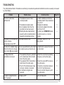
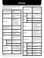
TROUBLESHOOTING
The problems described in this table are commonly encountered operational malfunctions and are usually not caused
by circuit failure.
Problem
The VC-H1 cannot be
switched ON.
The power to the camera and
monitor units are
automatically turned OFF.
Probable Cause
Corrective Action
1 The batteries have not been
correctly loaded.
1 Load the batteries so that their
polarities match those marked on
the VC-H1.
2 The batteries became dead.
2 Replace the batteries.
3 An AC adapter other than the
3 Use the AC adapter that came
provided one has been used.
with the VC-H1.
4 Shorting the video input terminal
4 Contact your KENWOOD dealer,
power line with an external element
customer service, or service
caused the internal fuse to blow.
station.
The Battery Saver is ON.
If necessary, switch OFF the
Battery Saver.
Page Ref.
3
3
4
—
11
The color of a recalled image The lens was affected by direct light Be careful not to expose the lens to
differs from that of an image
from a light source such as the sun. any direct light.
shown when [S] was pressed.
—
An image cannot be
transmitted or received.
No audio is output from the
VC-H1 speaker.
1 The operating frequency selected
on the transceiver did not match
that of the other party.
2 The selected SSTV mode did not
match that of the other party.
3 The VC-H1 and transceiver have
not been correctly connected.
4 An interference signal was
received.
1 Select the exact same operating
frequency as the other party.
—
2 Select the same SSTV mode as
the other party.
3 Check the connections between
the VC-H1 and transceiver.
4 Move to another frequency with
the other party.
7
AF Mute is OFF.
Switch AF Mute ON.
5
—
13
15
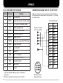
APPENDIX
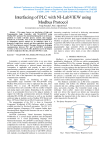
VC-H1 DATA PORT PIN FUNCTIONS
Pin No.
Pin Name
Function
1
NC
2
SSDO
3
6V
+6 V output (not usually used)
4
DG
Digital signal ground
5
TXD
Serial data transmission
6
RXD
Serial data reception
7
SSPTT
Image data PTT
8
FSSDO
Image data output (Fast FM mode) 1
9
SSDI
10
NC
No connection
11
PTT
Audio PTT
12
3MS
+3.5 ~ +6 V input
13
SP
Audio input (0.5 W/ 8 Ω)
14
MIC
Microphone input
15
MSP
Audio input 2
No connection
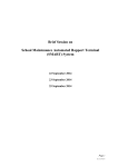
CONNECTION DIAGRAM WITH TS-570 OR TS-870
Note: Pin 1 of the connector, which mates with the VC-H1 DATA port,
can be identified with a triangle mark on the connector. Pin 1 is located
just below the mark.
Image data output (not usually used)
VC-H1 (DATA port)
TS-570 or TS-870
(ACC 2 connector)
Image data input
13
16
1
2
G
Ground
This pin is used for a connection with the DATA connector on
a TM-255, TM-455, TM-733, TM-V7, or TM-G707
transceiver.
This pin is used when AF power is over 0.5 W/ 8 Ω.
16
9
10
11
12
5
6
7
8
1
2
3
4
ACC 2 Connector
(Rear panel view)
P1
P2
P3
P4
P5
P6
P7
P8
P9
P10
P11
P12
P13
P14
P15
P16
NC
SSDO
6V
DG
TXD
RXD
SSPTT
FSSDO
SSDI
NC
PTT
3MS
SP
MIC
MSP
G
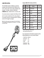
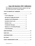
COMPUTER CONTROL
Computer COM Port Pin Functions (9-Pin Port)
If the dedicated program is installed, your personal
computer can be connected with the COM jack of the
VC-H1, then the VC-H1 can be easily controlled via the
computer. For details, contact your authorized
KENWOOD dealer, customer service, or service center.
Pin No.
Pin Name
q
DCD
No connection
w
RXD
RX data
Pin 5 1
e
TXD
TX data
Pin 6 1
r
DTR
Data Terminal Ready
DSR 2
t
GND
Signal ground
y
DSR
Data Set Ready
DTR 2
u
RTS
TX request
CTC 2
i
CTS
TX enable
RTS 2
o
RI
You can also connect a computer to the DATA port of the
VC-H1 in order to control the VC-H1 via the computer.
This, however, asks you to manually send ST commands
to the VC-H1 through the computer.
Note: Pin 1 of the connector, which mates with the VC-H1 DATA port,
can be identified with a triangle mark on the connector. Pin 1 is located
just below the mark.
1
2
Function
No connection
To
—
Pin 16 1
—
Pins of the DATA port on the VC-H1
No connection with the VC-H1
Use an appropriate communications program to set the
following parameters on your personal computer.
•
•
•
•
•
•
1
2
6
3
7
4
8
Transfer rate:
Data length:
Stop bit:
Parity:
Flow control:
Data format:
9600 bps
8 bit
1 bit
Non
Non
ASCII
5
9
Computer COM Port
17
■
■
Commands List
Pin No.
Pin Name
Function
q
STS
SSTV mode switch/
Inquiry of current SSTV mode
w
STC
Call sign superimposition
e
STM
Message superimposition
r
STR
RSV superimposition
t
STP
Image capture
y
STT
Image transmission
Commands Format
Note: Use capital letters to enter a command name.
A STS command should consist of a command
name, space, parameter, and [CR]; ex. STS 0 [CR].
Parameter
Function
Parameter
Function
Non
Inquiry of
current SSTV
mode
4
Scottie S1 1
0
Robot 36
5
Scottie S2 1
1
Robot 72
6
Martin M1 1
2
AVT 90 1
7
Martin M2 1
3
AVT 94 1
8
Fast FM
1
18
Compatible
A STC command should consist of a command name,
space, call sign, comma, color parameter, and [CR];
ex. STC JA1YKX, 1 [CR]. You can enter up to 8
characters as a call sign, using “0” to “9”, “A” to “Z”,
“/”, “-”, “!”, “?”, or a space. The parameters of call
sign colors are listed below:
Parameter
Function
Parameter
Function
0
black
4
green
1
blue
5
light blue
2
red
6
yellow
3
purple
7
white
The formats of STM and STR commands are the
same as of STC commands except that a message or
RSV replaces a call sign; ex. STM CQ SSTV, 2[CR].
The characters which can be entered are also the
same as for STC commands.
• Up to 9 characters can be entered as a message.
• Up to 10 characters can be entered for a RSV.
STP and STT commands consist of a command
name and [CR]; ex. STP[CR].
SPECIFICATIONS
Specifications are subject to change without notice due
to developments in technology.
Still picture modulation method
SCFM through digital signal
processing
Still picture demodulation
method
Arc tangent angle change
detection through digital signal
processing
Still image mode
Robot (color) 36/
Robot (color) 72/ AVT 90 1/
AVT 94 1/ Scottie S1 1/
Scottie S2 1/ Martin M1 1/
Martin M2 1/ Fast FM
Modulation mode (transceiver
F5
to be connected with:)
Microphone
External bias/ Electret
condenser microphone
Speaker
1 W (max.),16 Ω
L CD
1.8 inch TFT/ color LCD,
coated for preventing surface
reflection
Rated
voltage
External power
input (DC IN)
Video signal output
1
Compatible
Still picture Microphone
signal output
(level: not
SSDO
variable)
FSSDO
1 Vp-p ±20% (Fast FM)
50 mVp-p ±20% (other than
Fast FM)
50 mVp-p ±20%
1.5 Vp-p ±20% (Fast FM only)
Image memory
1 display buffer (175K bytes,
non-compressed)/
10 compressed images (max.)
conform to JPEG/ Approx. 4
years memory backup
Expansion port
115 kbps, RS232C level
computer interface/
Asynchronous 8 bit/ 1 stop bit/
No parity/ Non flow control
Transceiver interface
9600 bps, CMOS level output
(TXD)/ RS232C level input
(RXD)/ Negative logic input
and output
6.0 V DC ±10%
Battery terminals 6.0 V DC (4 AA alkaline batteries)
Video signal input
Still picture signal input
50 mVp-p ~ 3.0 Vp-p
600 Hz ~ 6.8 kHz (Fast FM)
1.0 kHz ~ 2.4 kHz (other than
Fast FM)
Image capture in
650 mA (max.)
progress
75 Ω, 1 Vp-p (140 IRE) ±15%,
NTSC/ Sub-carrier frequency:
within ±200 Hz/ Non DC offset
Current
consumption LCD in use
75 Ω, 1 Vp-p (140 IRE) ±15%,
NTSC
Temperature Use
range
Storage
Standby
450 mA (average)
100 mA (average)
0°C ~ +40°C
–20°C ~ +60°C
19