1
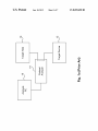
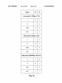
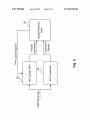
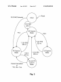
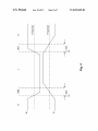
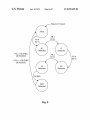
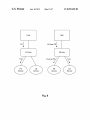
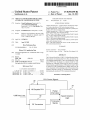
US008095698B2
(12) United States Patent
(10) Patent N0.:
(45) Date of Patent:
Santhanam et a1.
(54)
CIRCUITS AND METHODS FOR RELIABLE
W0
(75) Inventors: Gopal Santhanam, Sunnyvale, CA
(US); Kumaran Santhanam,
Sunnyvale, CA (U S); Etai Bruhis, Palo
Alto, CA (US)
WO 2007092997 A1 *
8/2007
OTHER PUBLICATIONS
Catalyst Enterprises Inc., “Conquest Series USB Protocol Analyz
ers,” product speci?cation, 2006, entire document relevant.
Catalyst Enterprises Inc ., “Bus & Protocol Analyzers,” product speci
?cation, 2005, entire document relevant.
(73) Assignee: Total Phase, Inc., Sunnyvale, CA (US)
Notice:
Jan. 10, 2012
FOREIGN PATENT DOCUMENTS
AUTOMATIC USB SPEED DETECTION
(*)
US 8,095,698 B2
Catalyst Enterprises Inc., “USB 1.x/2.0 Analyzer Exerciser Tester,”
product speci?cation, entire document relevant.
Ellisys, “Ellisys USB Explorer 260 Getting Started Guide,” manual,
Subject to any disclaimer, the term of this
patent is extended or adjusted under 35
Nov. 22, 2007, entire document relevant.
U.S.C. 154(b) by 88 days.
Ellisys, “Ellisys USB Explorer 200 Getting Started Guide,” manual,
Feb. 13, 2006, entire document relevant.
(21) App1.No.: 12/544,219
Finisar Corporation, “Bus DoctorTM RX Analyzer,” product speci?
(22) Filed:
cation, entire document relevant.
Hitex, “USB Agent Explores the secrets of USB,” brochure, Jun.
2001, entire document relevant.
Aug. 19, 2009
(65)
Prior Publication Data
US 2010/0049880 A1
(Continued)
Feb. 25, 2010
Primary Examiner * Eron J Sorrell
Related US. Application Data
(74) Attorney, Agent, or Firm * Van Pelt, Yi & James LLP
(60) Provisional application No. 61/090,223, ?led on Aug.
19, 2008.
(51)
Int. Cl.
G06F 3/00
(57)
The Universal Serial Bus (“USB”) 2.0 Speci?cation de?nes
three speeds of communication for its bus, and each has its
oWn signaling characteristics. Due to the uniqueness of each
speed, PHYs must be placed in a separate mode for each
signaling rate. Although USB devices may knoW its commu
nication speed, a general purpose USB analyzer must be able
to analyze all USB communications. Rather than force the
user to manually set the operating mode of the analyzer, this
invention describes circuits for automatically and reliably
determining the monitored USB communication speed.
(2006.01)
(52)
US. Cl. ....................................................... .. 710/15
(58)
Field of Classi?cation Search ...................... .. None
See application ?le for complete search history.
(56)
References Cited
U.S. PATENT DOCUMENTS
7,139,344 B2 *
11/2006
Crutch?eld et a1. ........ .. 375/354
2003/0223486 A1*
12/2003
Hsu ................ ..
2008/0140885 A1*
6/2008 Collins
2009/0222685 A1*
9/2009
.. 375/224
710/67
28 Claims, 7 Drawing Sheets
Foster et al. ................ .. 713/500
PHY Control Signals
20
r’
1
ABSTRACT
,
K54
HS Capable PHY
Packet
Information
USB Data Lines
22
7
r.)
Logic
Transceiver
Signals
7
FS Transceiver
Speed Detection
US 8,095,698 B2
Page 2
OTHER PUBLICATIONS
LeCroy Corporation, “LeCroy AdvisorTM USB 2.0 Bus and Protocol
Analyzer User Manual,” user manual, Jul. 2007, entire document
relevant.
LeCroy Corporation, “LeCroy USBMobileHSTM Protocol Analyzer
User Manual,” user manual, Jul. 2007, entire document relevant.
LeCroy Corporation, “LeCroy USBTracerTM USB 2.0 Design &
Veri?cation System User Manual,” user manual, Jul. 2007, entire
document relevant.
Author Unknown, “Universal Serial Bus Speci?cation,” speci?ca
tion, Apr. 27, 2000, entire document relevant.
* cited by examiner
US. Patent
Jan. 10, 2012
Sheet 1 of7
US 8,095,698 B2
Nw
62839m2.
2W/my?5H\89:5
.3‘
609i Lmwbcd‘
:2BE:2.2“.
US. Patent
Jan. 10, 2012
Sheet 2 of7
Signal
D+
US 8,095,698 B2
D
Low-speed (1.5 Mbps, 3.3V)
J
O
1
K
1
0
SE0
0
O
SE1
1
1
Full-speed (12 Mbps, 3.3V)
J
1
O
K
O
1
SE0
0
O
SE1
1
1
High-speed (480 Mbps, 400 mV)
J
1
O
K
O
1
SE0
0
O
SE1
1
1
Fig. 1b
US. Patent
Jan. 10, 2012
Sheet 3 of7
US 8,095,698 B2
1
6289;.
>62:918506
289m
N.5
a
1
mEwwcDaj
US. Patent
Jan. 10, 2012
Sheet 4 of7
US 8,095,698 B2
Reset
FS SYNC Detected
3.3V SEO
225 ns
HS Capture
Mode
FS Capture
Mode
LS Capture
* 3.3V SEO
FS K
225 ns
333 ns
LS-over-FS
Packet Completed
Capture
Mode
or
* FS J for ~3 us
Fig. 3
Mode
US. Patent
Jan. 10, 2012
905,;
Sheet 5 of7
US 8,095,698 B2
205 ,;
w.5
US. Patent
Jan. 10, 2012
Sheet 6 of7
US 8,095,698 B2
Reset or Timeout
FSJ
FS K
83 ns
K1
Detected
J1
Detected
FS J / FS SYNC
DETECTED
FS K
83 ns
~FS J / ~FS SYNC
DETECTED
J2
Detected
FS SEO
SEO
Detected
Fig. 5
K2
Detected
US. Patent
Jan. 10, 2012
Sheet 7 of7
Host
Psi
US 8,095,698 B2
Host
LS-over-FSi
FS Hub
LS-over-FS
Fig. 6
US 8,095,698 B2
1
2
CIRCUITS AND METHODS FOR RELIABLE
AUTOMATIC USB SPEED DETECTION
traf?c are disclosed, comprising of a ?rst receiver for receiv
ing USB traf?c; and a second receiver for receiving USB
traf?c; Wherein the ?rst receiver and the second receiver are
placed in parallel in receiving the USB traf?c; and Wherein
CROSS REFERENCE
the ?rst receiver may be a high-speed capable receiver and the
second receiver may be a full-speed receiver. The signaling
mode may be detected by the ?rst receiver and the second
receiver by the steps of: entering a capture mode from an
initial mode upon detecting a corresponding SYNC
This application claims priority from a provisional patent
application entitled “Methods for Reliable Automatic USB
Speed Detection Using Multiple Physical Interfaces” ?led on
Aug. 19, 2008 and having an Application No. 61/090,223.
Said application is incorporated herein by reference.
sequence; entering a hi gh- speed capture mode upon detecting
FIELD OF INVENTION
a SEO signal for a ?rst duration; entering a loW-speed capture
mode from the high-speed capture mode upon detecting a
This invention relates to circuits and methods for analyzing
of USB traf?c and, in particular, to circuits and methods for
FS-K signal; entering a full-speed capture mode from the
high-speed capture mode upon detecting a FS-J signal; enter
ing a low-speed-over-?lll-speed mode from the full-speed
determining USB signaling speed in analyZing USB traf?c.
capture mode upon detecting a FS-K signal for a second
BACKGROUND
The USB 2.0 Speci?cation de?nes three speeds of commu
20
nication: loW-speed (1.5 Mbps), full-speed (12 Mbps), and
high-speed (480 Mbps). Aside from the speed differences,
duration; entering a full-speed capture mode from the loW
speed-over-?lll-speed capture mode upon detecting a FS-J
signal for a third duration; and entering a full-speed capture
mode from the loW-speed-over-full-speed capture mode upon
packet completion.
each of these signaling rates also has unique signaling char
acteristics. Thus, a USB analyZer, Which sits passively on the
bus and monitors bus tra?ic, must be able to handle each of
these operating modes appropriately. FIG. 1a illustrates a
common setup for the USB analyZer Where a target host 10
transmits information to the target device 12 and a protocol
analyZer 14 analyZes the traf?c betWeen the target host 10 and
the target device 12. An analysis computer 16 can be setup to
interact With the protocol analyZer 14 in the examination of
such traffic.
The USB protocol speci?es a set of differential signals to
DESCRIPTION OF THE DRAWINGS
25
draWings in Which:
30
35
FIG. 4 illustrates sample LS signals, Where differences in
40
FIG. 5 illustrates the state diagram and transition condi
tions for PS SYNC detection.
FIG. 6 illustrates examples of FS and LS-over-FS traf?c
HS signaling runs at a much loWer signaling level (400 mV
45
patterns.
DETAILED DESCRIPTION OF THE PREFERRED
EMBODIMENTS
50
The preferred embodiments provide methods for highly
reliable automatic speed detection of USB signaling rates by
using both a full-speed receiver and a high-speed capable
PHY as inputs to an intelligent digital logic system. The
55
hoWever this device can be any high-speed capable receiver
Robust USB analyZers must be able to monitor all USB
speeds, and must therefore be capable of determining the
speed of the bus and con?guring the PHY appropriately. The
quick detection of these bus speeds is especially necessary in
rise times can cause single-ended (SEO or SE1) line-states for
225 ns at the Worst case.
ing have opposite polarities for their J and K line-states, and
compared to 3.3V). Thus, each signaling rate can be uniquely
described by its idle line-state.
The problem is that most HS capable PHYs can only effec
tively monitor a single speed during any one time period, and
must therefore be con?gured to that speed (LS mode, FS
mode, or HS mode). Furthermore, auto speed detection of
other products and technologies is knoWn to be unreliable.
FIG. 1b illustrates the line-states and signaling levels of the
three USB 2.0 signaling rates.
FIG. 2 illustrates a block diagram for automatic speed
detection.
FIG. 3 illustrates a state diagram and the transition condi
tions among the states.
(FS), loW-speed (LS), and high-speed (HS). It is important to
note that the J line-state also designates the idle state of the
bus for the FS and LS buses, and SEO is the idle line-state for
high-speed. It is also important to note that LS and FS signal
FIG. 1a illustrates a common protocol analyZer setup,
Where the USB traf?c passes through the protocol analyZer
and is captured and passed to the analysis computer.
transmit data across a bus Which are called D+ and D—. These
tWo lines can potentially have four different line-states, hoW
ever only three states are valid in the USB speci?cation. These
three valid line-states are called I, K, and SEO, and they are
illustrated in FIG. 1b for the three USB speeds: full-speed
The foregoing and other objects, aspects, and advantages
of the invention Will be better understood from the folloWing
detailed description of the preferred embodiment of the
invention When taken in conjunction With the accompanying
high-speed capable PHY can be an ULPI or UTMI receiver;
situations Where the bus may be changing back and forth
With associated control logic to provide packet level informa
betWeen speeds. An example of this Would be during the
high-speed negotiation process, in Which the analyZer must
tion. On the other hand, the FS receiver can simply be a device
that provides raW data-line information on a FS threshold
quickly sWitch to a HS mode from a FS mode in order to
capture the negotiation. Thus it Would be desirable to have
60
reliable methods for correctly determining the speed of the
USB bus.
SUMMARY
65
Brie?y, in a preferred embodiment of the present invention,
circuits for detecting USB signaling mode in analyZing USB
level. To differentiate the tWo devices, the ULPI/UTMI
devices Will be referenced as the PHY, While the other device
Will be called the FS receiver.
It should be noted that the present invention does not
require the use of the PHY to accomplish its goals. It is only
in the preferred embodiment that the PHY is used. In typical
scenarios it is a PHY that needs to be con?gured to the
appropriate mode, so the readily available signals (such as the
indication of an active packet) are taken advantage of. HoW
US 8,095,698 B2
3
4
ever, if speed detection is used for any purpose that does not
require a PHY then only the FS receiver is necessary, and the
indication of an active packet could be done through internal
?rst packet. This ensures that the next packet the analyZer sees
is a complete packet. While this Will drop the ?rst packet of an
already communicating bus, it is acceptable for an analyZer to
logic.
do this as it simply appears to the user as a marginally delayed
start of a capture.
A couple key features of the USB speci?cation are used to
accomplish reliable speed detection. The ?rst is that all HS
FOR FS and LS devices, an end-of-packet (EOP) signal is
an SEO line-state for tWo bit-times at the respective signaling
rate. As a result, the transition out of the initial state is treated
much like the rest of the logic; Wait for an SEO signal and
transition into the HS state. HoWever, the transition can only
signaling levels fall in a threshold that is beloW that of any FS
receiver. This means that all HS traf?c appears as an SEO
signal on PS receivers. The second is that after every SEO
signal, the data lines return to their idle stateiWhich is
unique to each speed. In the case of FS buses the D+ line is
high and the D- line is loW for its idle state. For LS buses, the
D- line is high and the D+ line is loW.
FIG. 2 illustrates one embodiment of the signal paths for
occur if the SEO is of a duration of at least 225 ns, due to issues
previously described and also illustrated in FIG. 4. Given this
approach, it must be ensured that the logic can transition out
of the initial state in the presence of the various bus condi
tions:
1. A LS EOP is approximately 1300 nsiWell above the
225 ns cut-off. Therefore it is guaranteed that an already
communicating LS bus Will transmit an SEO signal of the
the automatic speed detection in the preferred embodiment of
the present invention. Both the high speed capable PHY 20
and the FS receiver 22 are on the same USB data lines, but
they provide different information to the speed detection
logic. The PHY 20 provides packet information such as
Whether or not an active packet is on the bus. On the other
20
hand, the FS receiver 22 provides information on the current
state of the USB data lines using a 3.3V signal level threshold.
The speed detection logic 24 uses this information to con?g
ure the PHY to the appropriate bus speed using the PHY
control signals.
2. HS transmissions alWays appear as an SEO to a 3.3V
receiver, and Will therefore also guarantee a transition
out of the initial state in FIG. 3;
25
The preferred embodiment starts in an initial state upon
start-up. In this initial state all information from the PHY is
ignored, and can thus be turned off or preset to any reception
mode. The preferred embodiment presets the PHY into the
high-speed mode.
30
FIG. 3 illustrates a state diagram for the speed detection
logic and the transition conditions among the states. Note that
context of an active packet; all 3.3V level signals (PS I, K,
35
and
4. FS buses have an EOP of tWo bit-times, but their signal
ing rate causes this EOP to have a duration of approxi
mately 167 ns. Therefore, additional logic must be
employed to transition out of the initial state for an
already communicating FS bus. This is described as
follows. In order to handle the situation Where the cap
initial state to the FS state upon detecting a FS SYNC
pattern (see FIG. 5). The SYNC pattern is a special
in FIG. 5. The preferred embodiment accomplishes its speed
detection by transitioning into HS mode Whenever the FS
sequence that starts every package and is unique to each
signaling rate. Thus, by searching for this pattern, it can
be con?rmed Whether the bus is operating at FS or not.
receiver sees an SEO signal on the bus outside of the context
of a valid USB packet. This alloWs for maximum ?exibility as
it alloWs the analyZer to check if this is a truly an SEO signal,
or actually HS traf?c. If, While in HS mode, either of the USB
data-lines goes to a 3.3V signaling level, then the speed
detection unit transitions out of the HS mode. If it Was the D+
line that Went high, the analyZer is put into FS mode. If it Was
3. If no devices are plugged in, the lines Will default to an
SEO signal and cause a transition out of the initial state;
ture is started during an already communicating FS bus,
the speed detection logic Will also transition out of the
the transition conditions prefaced With a “ *” are outside of the
SEO) come from the FS receiver; and the FS SYNC Detected
signal comes from the FS SYNC detection module depicted
required duration, and alloW the speed detection unit to
transition out of the initial state (see FIG. 3);
40
Referring to FIG. 5, the FS SYNC detector Works by
searching for a speci?c pattern (KJKJ). Each of these bits
must have a duration that is Within the speci?cation for a FS
the D- line that Went high, the analyZer is put into LS mode.
bit-time. Detecting this sequence alloWs for a unique differ
entiation of FS signaling, hoWever the PHY must only be
transitioned into a FS mode after the packet is complete. This
is done so that the PHY only starts receiving full packets.
This decision can be made due to the unique idle line-states of
the LS and FS buses after an SEO signal.
the packet completes (an SEO signal is seen) before alerting
It should be noted that the preferred embodiment requires
that the SEO signal appear for a speci?c duration in order for
45
Thus, after detecting the SYNC pattern, the logic Waits until
the speed detection logic. After seeing the SEO signal, the
50
logic does an extra check to make sure that a PS I is detected
a transition to occur. The USB speci?cation for LS devices
immediately after the SEO signal. If so, the speed detection
de?nes that the rise and fall times of the data lines must be
unit is alerted that a FS SYNC Was detected, and Will transi
tion out of the initial state to the FS capable mode. If a PS I
betWeen 75 ns and 300 ns. This means that in the Worst case,
the LS bus can have an SEO line-state for as much as 225 ns
betWeen bits of a LS transmission (see FIG. 4). It Would be
unWise to sWitch the PHY to a high-speed mode during LS
signaling. Thus, the SEO signal must appear on the line for
55
The use of the FS SYNC as a transition into the FS mode is
not used outside of the initial state because it causes the
analyZer to drop the packet Whose SYNC Was detected. This
is due to the fact that the PHY is only changed into the
more than 225 ns in order to change to the HS mode.
This method Works quite Well during a capture, but it has
some issues at the very start of a capture. Due to the unique
60
requirements of a protocol analyZer, a capture may be started
on an already active bus. Furthermore, the capture may be
started in the middle of a transmission of a packet. Protocol
analyZers must therefore be robust to these situations and
handle them gracefullyiproviding users With inaccurate
information defeats the purpose of the tool. One method for
handling these situations is to simply Wait until the end of the
signal is not detected, the detection logic returns to the initial
state Without asserting the FS detected signal.
appropriate mode after the packet has completed. As
described earlier, it is acceptable of the analyZer to drop the
very ?rst packet on an already communicating bus, as it
simply appears as a slightly delayed start of a capture. Drop
ping packets at any other time Would defeat the purpose of the
65
tool, as the user Would be unable to differentiate from cap
tures in Which the analyZer dropped the packet or in Which the
devices under test never transmitted the packet.
US 8,095,698 B2
6
5
LS-over-FS signaling is a unique USB signaling mode in
Which FS polarity signals are sent at LS signaling rates. This
5. The circuit for detecting USB signaliZing mode in ana
lyZing USB traf?c, comprising:
mode Will be encountered Whenever a LS device is connected
a ?rst receiver for receiving a stream of USB traf?c; and
a second receiver for receiving the stream of USB traf?c;
Wherein the ?rst receiver and the second receiver are placed
in parallel to the stream of USB tra?ic; and
to a FS bus (i.e., through a FS hub). The hub is responsible for
keeping out FS signals to the LS device, and inverting the
polarity of the LS-over-FS signals so that they look correct to
LS devices. On the other hand, FS devices connected in such
a con?guration Will see both FS signals and LS-over-FS sig
Wherein the USB signaling mode is detected by the ?rst
receiver and the second receiver by:
nals (see FIG. 6). Thus, a robust protocol analyZer that Wishes
entering a capture mode from an initial mode upon
to shoW all communication that occurs on the bus must be able
detecting a corresponding SYNC sequence;
entering a high-speed capture mode upon detecting a
SEO signal for a ?rst duration;
entering a loW-speed capture mode from the high-speed
capture mode upon detecting a FS-K signal;
entering a full-speed capture mode from the high-speed
capture mode upon detecting a FS-J signal;
entering a low-speed-over-?rll-speed mode from the
full-speed capture mode upon detecting a FS-K signal
to shoW both the FS and LS-over-FS signals that may be
present, and change the setting of the PHY appropriately if
necessary.
The present invention Will transition to the LS-over-FS
mode from the FS mode When a FS K signal is seen on the bus
for approximately 333 ns outside the context of an active
packet. The timing of this FS K signal is such that it Would be
impossible for it to occur outside of the context of an active
packet, except during the beginning of a LS-over-FS SYNC
sequence or a FS resume signal. Therefore, if speci?c safety
measures are put in place, it uniquely describes the LS-over
entering a full-speed capture mode from the loW-speed
over-full-speed capture mode upon detecting a FS-J
FS signaling mode, and can be used to cause a transition and
change in the PHY The transition out of the LS-over-FS mode
is done in a number of Ways. The most obvious is the transi
tion back to FS mode once a packet completes. Some safety
for a second duration;
20
signal for a third duration; and
entering a full-speed capture mode from the loW-speed
over-full-speed capture mode upon packet comple
25
tion.
6. The circuit of claim 5 Wherein the detection of the SEO
measures are also put in place in case a packet never appears
(such as during a resume signal). Speci?cally, if a FS J signal
is seen on the bus for more than 3 us outside the context of an
signal, the FS-K signal, the FS-] signal is performed by the
active packet, then the PHY is reverted back to PS. This
second receiver.
7. The circuit of claim 5 Wherein the ?rst receiver provides
duration is chosen so that it can not happen before the PHY
has an opportunity to assert the validity of a packet, but is still
fast enough to be able to transition and capture the next
packet. Furthermore, as in all the previous states, if an SEO
signal is seen on the bus for at least 225 ns outside of the
context of an active packet, then the PHY is reverted back to
HS.
Further note that the multiple receivers may be on a single
30
an indication of an active packet.
8. The circuit of claim 5 Wherein the second receiver is used
35
chip, or be separated on multiple chips, but must be operated
simultaneously. Also, initially the analyZer may transition out
of the initial state directly into the LS mode by looking for a
40
to detect SYNC and EOP as an indication of an active packet.
9. The circuit of claim 5 Wherein the ?rst duration is a
minimum of 225 ns.
10. The circuit of claim 5 Wherein the second duration is a
minimum of 333 ns.
11. The circuit of claim 5 Wherein in the entering a high
speed capture mode step, the detection of the SEO signal is not
performed during the receiving of a valid packet.
LS SYNC sequence. In an alternative embodiment, the initial
12. The circuit of claim 5 Wherein in the entering a full
state of the PHY canbe preset into the FS mode, and the speed
speed capture mode from the low-speed-over-?rll-speed cap
detection logic can then use the PHY’s internal logic to detect
ture mode step, the detection of the FS-] signal is not per
formed during the receiving of a valid packet.
the FS SYNC (instead of doing it manually through the FS
receiver signals). In a further alternative embodiment, the
45
13. The circuit of claim 5 Wherein in the entering a loW
generation of the active packet signal for PS, LS, and LS
over-FS signaling can be done manually by processing the
speed-over-?rll-speed capture mode step, the detection of the
FS-K signal is not performed during the receiving of a valid
raW signals of the receiver, and tracking the SYNC and EOP
packet.
signals.
We claim:
50
full-speed mode.
1. A circuit for detecting USB signaliZing mode in analyZ
ing USB tra?ic, comprising:
15. The circuit of claim 5 Wherein in the entering a capture
mode from an initial mode step, the capture mode is the
a ?rst receiver con?gured to receive a stream of USB tra?ic
and provide an indication of an active packet;
a second receiver con?gured to receive the stream of USB
loW-speed mode.
55
a ?rst receiver for receiving a stream of USB traf?c,
Wherein the ?rst receiver is a high-speed capable
receiver; and
60
ond receiver.
2. The circuit of claim 1 Wherein the ?rst receiver is a
high-speed capable receiver.
3. The circuit of claim 1 Wherein the second receiver is a
full-speed receiver.
4. The circuit of claim 2 Wherein the second receiver is a
full-speed receiver.
16. A circuit for detecting USB signaliZing mode in ana
lyZing USB traf?c, comprising:
traf?c in parallel With the ?rst receiver and provide state
information of the stream of USB traf?c; and
a speed detection logic con?gured to detect a USB signal
iZing mode at least in part based on the indication from
the ?rst receiver and the state information from the sec
14. The circuit of claim 5 Wherein in the entering a capture
mode from an initial mode step, the capture mode is the
65
a second receiver for receiving the stream of USB traf?c,
Wherein the second receiver is a full-speed receiver;
Wherein the ?rst receiver and the second receiver are placed
in parallel to the stream of USB tra?ic; and
Wherein the USB signaling mode is detected by the ?rst
receiver and the second receiver by:
entering a capture mode from an initial mode upon detect
ing a corresponding SYNC sequence;
US 8,095,698 B2
8
7
entering a loW-speed capture mode from the high-speed
24. The circuit of claim 23, Wherein the predetermined
signal level threshold is 3.3 V.
25. The circuit of claim 1, Wherein the state information
capture mode upon detecting a FS-K signal by the sec
comprises information for detecting FS-K signals and FS-]
ond receiver;
entering a full-speed capture mode from the high-speed
capture mode upon detecting a FS-J signal by the second
26. The circuit of claim 1, Wherein the speed detection
logic is further con?gured to con?gure the ?rst receiver based
entering a high-speed capture mode upon detecting a SEO
signal for a ?rst duration by the second receiver;
signals.
on the detected USB signaliZing mode.
receiver;
27. The circuit of claim 1, Wherein the USB signaling mode
is detected by the ?rst receiver and the second receiver by:
entering a high-speed capture mode upon detecting a SEO
signal for a ?rst duration;
entering a loW-speed capture mode from the high-speed
capture mode upon detecting a FS-K signal; and
entering a full-speed capture mode from the high-speed
capture mode upon detecting a FS-J signal.
28. The circuit of claim 1 Wherein the USB signaling mode
is detected by the ?rst receiver and the second receiver by:
entering a loW-speed-over-full-speed mode from the full
speed capture mode upon detecting a FS-K signal for a
second duration;
entering a full-speed capture mode from the loW-speed
over-full-speed capture mode upon detecting a FS-J sig
nal for a third duration; and
entering a full-speed capture mode from the loW-speed
over-full-speed capture mode upon packet completion.
17. The circuit of claim 16 Wherein the ?rst receiver pro
vides an indication of an active packet.
18. The circuit of claim 16 Wherein the second receiver is
used to detect SYNC and EOP as an indication of an active
entering a capture mode from an initial mode upon detect
20
packet.
19. The circuit of claim 1 6 Wherein in the entering a capture
mode from an initial mode step, the capture mode is the
full-speed mode.
20. The circuit of claim 1 6 Wherein in the entering a capture
mode from an initial mode step, the capture mode is the
25
loW-speed mode.
22. The circuit of claim 5, Wherein the second receiver
comprises a full-speed receiver.
23. The circuit of claim 1, Wherein the second receiver is
con?gured to provide state information of the stream of USB
tra?ic based at least in part on a predetermined signal level
threshold.
entering a loW-speed capture mode from the high-speed
capture mode upon detecting a FS-K signal;
entering a full-speed capture mode from the high-speed
capture mode upon detecting a FS-J signal;
entering a loW-speed-over-full-speed mode from the full
speed capture mode upon detecting a FS-K signal for a
21. The circuit of claim 5, Wherein the ?rst receiver com
prises a high-speed capable receiver.
ing a corresponding SYNC sequence;
entering a high-speed capture mode upon detecting a SEO
signal for a ?rst duration;
30
second duration;
entering a full-speed capture mode from the loW-speed
over-full-speed capture mode upon detecting a FS-J sig
nal for a third duration; and
entering a full-speed capture mode from the loW-speed
over-full-speed capture mode upon packet completion.
*
*
*
*
*