1
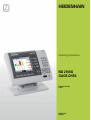
Operating Instructions
ND 2100G
GAGE-CHEK
Software Version
2.60.x
English (en)
10/2011
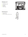
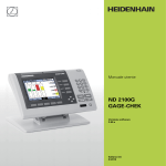
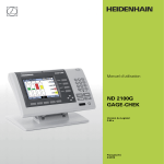
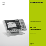
ND 2100G Introduction
1
2
3
4
5
6
7
8
9
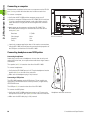
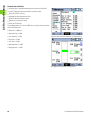
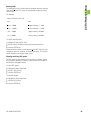
LCD screen
Soft keys
Dimension keys
Command keys
Arrow cursor keys
Numeric Keypad
Fast track keys
Send key
LCD on/off key
8
7
3
6
1
7
8
9
4
5
6
1
2
3
0
+/-
4
2
5
enter
finish
cancel
quit
9
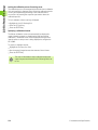
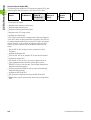
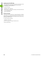
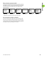
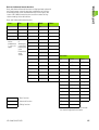
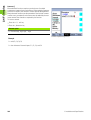
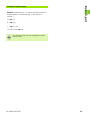
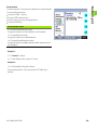
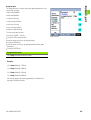
ND 2100G panel keys
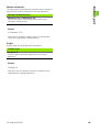
Panel keys are used to initiate feature measurements, apply
tolerances, send reports of measurement results and configure
operational parameters.
Panel function key
Panel key
Soft keys: Functions change in support of the activities displayed
on the LCD.
Dimension keys: Can be assigned one of six hot key functions
for use when DRO screen is displayed. When graph, bar value or
data screens are displayed, dimension keys are used to display
values for single dimensions or a smaller group of dimensions.
Command keys: Control measurement and data entry
processes.
enter
finish
cancel
quit
Arrow cursor keys: Used to scroll through lists and navigate
menus and setup screen data fields.
Fast track keys: Two programmable fast track keys are used to
perform frequently used functions. These keys can easily be
located by touch without taking your eyes off the part. Users can
program either fast track key as described later in the Hotkeys
portion of Chapter 2: Installation, Setup and Specifications.
ND 2100G GAGE-CHEK
3
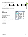
Panel function key
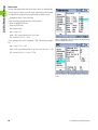
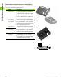
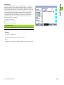
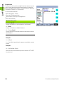
Numeric keypad: Used to enter numeric data. Additionally, the
decimal point key and +/- key are used to adjust the contrast
of the LCD display.
Panel key
7
8
9
4
5
6
1
2
3
0
+/-
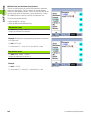
Send key: Used to transmit measurement results to a computer,
USB printer or USB flash drive.
LCD On/Off key: Press the LCD on/off button to turn the LCD
display off without removing power from the ND 2100G. Press
the button a second time to restore the LCD display. Additionally,
the LCD On/Off key can be used to clear channel calibrations,
delete data stored for a single part or delete data stored for all
parts.
4
Preface
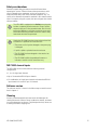
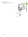
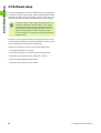
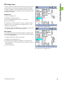
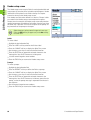
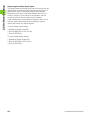
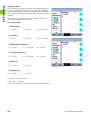
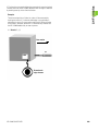
ND 2100G rear panel
1
2
3
4
5
6
7
Power switch
Power connection with fuse
Ground (protective ground)
Encoder inputs
Relay outputs
Parallel I/O port
RS-232-C interface
5
1
3
6
1
1
4
1
2
7
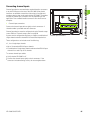
ND 2100G side panel
1
2
3
Speaker/headset jack
USB Type A connector
RJ-45 Foot switch/hand switch/keypad connector
1
2
1
3
ND 2100G GAGE-CHEK
5
Information contained in this
manual
This User's manual covers the operation, installation, setup and
specifications of the ND 2100G. Operating information is contained in
chapter 1. Installation, setup instructions and specifications are
contained in chapter 2.
Fonts used in this manual
The following fonts are used to indicate operator controls or to show
emphasis:
Operator controls - soft keys and other panel keys are shown in
upper case
Emphasis - Items of special interest or concepts that are
emphasized to the user are shown in bold type
Showing sequences of key presses
The ND 2100G user performs sequences of soft key and panel key
presses to measure part features and complete other tasks. These
sequences are indicated using text as shown in the following
example:
Press the MENU... soft key, press the DATUM... soft key and then
press the MASTER soft key is sometimes abbreviated as:
Press MENU/DATUM/MASTER
Symbols within notes
Notes are marked with symbols on the left indicating the type, or
potential severity of the information.
General Information
This is additional or supplementary information about an
activity or concept.
Warning
This warns of a situation or condition that could lead to
measurement errors, equipment malfunction or
equipment damage. Do not proceed until the message is
read and understood.
Caution - Risk of electric shock
This warns of a situation or condition that could lead to
electrical shock and to personal injury or death. Do not
proceed until the message is read and understood.
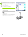
6
Preface
Safety considerations
General accepted safety precautions must be followed when
operating the system. Failure to observe these precautions could
result in damage to the equipment, or injury to personnel. It is
understood that safety rules within individual companies vary. If a
conflict exists between the material contained in this manual and the
rules of a company using this system, the more stringent rules should
take precedence.
The ND 2100G is equipped with a 3-wire power plug that
includes a separate ground connection. Always connect
the power plug to a 3-wire grounded outlet. Use of 2-wire
power plug adapters or any other connection accessories
that remove the third grounded connection create a safety
hazard and should not be permitted.
Unplug the ND 2100G from the power outlet and seek the
assistance of a qualified service technician if:
The power cord is frayed or damaged or the power plug
is damaged
Liquid is spilled or splashed onto the enclosure
The ND 2100G has been dropped or the exterior has
been damaged
The ND 2100G exhibits degraded performance or
indicates a need for service some other way
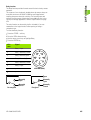
ND 2100G channel inputs
The ND 2100G can be connected to the following channel
configurations.
1, 4, or 8 single input channels
Up to 16 networked RS-232 input channels
Or combinations of single input channels and networked RS-232
input channels for a total of up to 16 channels
Software version
The software version is shown in the About setup screen discussed
later in chapter 2.
Cleaning
Use only a cloth dampened with water and a mild detergent for
cleaning the exterior surfaces. Never use abrasive cleaners, and never
use strong detergents or solvents. Only dampen the cloth, do not use
a cleaning cloth that is dripping wet.
ND 2100G GAGE-CHEK
7
8
Preface
1 Operation .... 17
1.1 ND 2100G Overview .... 18
Overview .... 18
1.2 Basic operation of the ND 2100G .... 20
Switching on the ND 2100G .... 20
Switching off the ND 2100G .... 20
1.3 Panel key descriptions .... 21
Dimension keys .... 23
1.4 LCD screens and menus .... 26
Screen navigation .... 26
Home screen .... 27
DRO screen .... 27
View soft keys and screens .... 28
View soft keys for subgroups of one .... 28
Dimension graphs for SPC subgroups of one .... 28
Dimension histograms for SPC subgroups of one .... 29
Bar and dial current value displays .... 30
Dimension data tables for SPC subgroups of one .... 31
View soft keys for subgroups greater than one .... 32
Dimension x charts for subgroups greater than one .... 32
Dimension r charts for subgroups greater than one .... 33
Dimension data tables for subgroups greater than one .... 34
in/mm menu items .... 35
Master menu items and screens .... 35
Master screen for calibrating encoder datums .... 35
Master screen for calibrating transducer ranges .... 36
Menu soft keys .... 37
The datum menu functions .... 37
The Extra menu functions .... 38
Fast3 .... 39
Setup menu functions .... 40
ND 2100G GAGE-CHEK
9
1.5 Operating instructions .... 41
Select a part to begin a measurement .... 42
Establish a reference for the measurement .... 43
Calibrating channels using the Master function .... 43
Calibration of a single reference point .... 44
Calibration groups (G1, G2, G3...G18) .... 45
Calibrations of transducer resolution (Min-Max calibrations) .... 46
Establishing a temporary dimension reference .... 48
Zeroing a dimension reference .... 48
Presetting a dimension reference to a specific value .... 49
Clearing channel calibrations .... 50
Clearing dimension references (presets) .... 50
Conducting measurements .... 51
Manual measurements .... 51
Sequential measurements .... 52
Dynamically sampled measurements .... 53
Semi-automated measurements .... 54
Reviewing measurements .... 55
Printing reports or sending results to a computer .... 55
Printing reports .... 55
Sending data to a computer .... 56
Data reports .... 57
Clearing stored measurement data .... 58
10
2 Installation, Setup, Formulas and Specifications .... 59
2.1 ND 2100G Shipment Contents .... 60
Items included with the ND 2100G .... 60
Optional items possibly included .... 60
Repackaging the ND 2100G .... 61
2.2 Hardware Installation .... 62
Assembling the mounting stand .... 62
Benchtop location and mounting .... 62
Arm mounting (optional) .... 63
Connecting power .... 64
Connecting channel inputs .... 65
Connecting a computer .... 66
Connecting headphones and USB printer .... 66
Connecting headphones .... 66
Connecting a USB printer .... 66
Connecting an optional foot switch or remote keypad .... 67
2.3 Software setup .... 68
Setup menu .... 69
Accessing and navigating the Setup menu .... 70
Using dimension keys in the setup mode .... 71
Entering data into setup fields .... 71
Deleting data entries .... 72
Entering setup parameters .... 72
Changing the channel or dimension number .... 72
Entering parameters .... 73
Copying parameters to other parts, dimensions or channels .... 73
Saving a parameter and advancing to the next .... 74
Saving a parameter and returning to the Setup menu .... 74
Discarding changes and returning to the Setup menu .... 74
Leaving the Setup menu .... 75
Printing ND 2100G setup configurations .... 75
Saving or loading ND 2100G configurations .... 75
Minimum setup requirements .... 76
Setup screens .... 76
About setup screen .... 76
Dimensions setup screen .... 77
Creating part numbers .... 77
Selecting part numbers .... 77
Labeling parts and dimensions .... 78
Defining visible and hidden dimensions .... 78
Copying dimension parameters to other parts .... 79
Deleting parts .... 79
Formats setup screen .... 80
Specifying a dimension .... 80
Specifying radius or diameter .... 80
Display resolution .... 81
Formulas setup screen .... 82
Variables setup screen .... 83
ND 2100G GAGE-CHEK
11
Tolerances setup screen .... 84
Nominal values with tolerances .... 85
Nominal with +/- tolerances .... 85
Nominal with ++ tolerances .... 86
Nominal with -- tolerances .... 87
Nominal with fixed limits .... 88
Specifying an audio alert .... 89
Mirror values .... 90
SPC setup screen .... 91
Subgroup size .... 91
Max subgroups .... 91
Graph points .... 92
Next record ID .... 92
Dimension .... 92
UCL and LCL .... 93
x, r Ucl and Lcl .... 93
Warning limits .... 95
Showing and hiding SPC graphs .... 95
Header setup screen .... 96
Labels .... 96
Prompts .... 96
Memory setup screen .... 97
S labels setup screen .... 97
S formulas setup screen .... 98
Globals setup screen .... 98
Channels setup screen .... 99
Specifying the input channel .... 99
Selecting the channel input type .... 100
Specifying input channel setup parameters .... 101
Master link probe balancing .... 101
Setting the resolution for the linked channels .... 102
Specifying channel input resolution .... 103
Specifying units of measure .... 104
Reversing channel input polarity .... 104
Specifying encoder reference marks .... 105
Changing the machine zero position .... 106
Enabling scale error notification .... 106
Calibrating LVDT and HBT transducer gain .... 106
Centering (nulling) LVDT and HBT transducers .... 107
Selecting an external RS-232 channel .... 108
Specifying an RS-232 input port .... 108
EnDat 2.2 encoder interface .... 109
Master setup screen .... 111
Specifying the number of calibration points .... 111
Selecting calibration type .... 111
Locking the calibration process if warnings occur .... 112
Specifying a calibration interval .... 112
Using dynamic Min/Max values for calibration .... 113
Specifying Min and Max calibration warnings .... 114
12
SLEC setup screen .... 115
SLEC or LEC, which is right for my application? .... 115
LEC (Linear error correction) .... 115
SLEC (Segmented linear error correction) .... 116
SLEC setup procedure .... 118
Clear all datums .... 118
Cycle power & set machine zero .... 119
Clear old values & disable SLEC .... 120
Enter machine zero offset .... 121
Enter new station values .... 122
Enable SLEC .... 123
Display setup screen .... 123
Radix for numeric displays .... 123
Display mode for angles .... 123
Startup angular and linear display modes .... 124
Bar graph orientation .... 125
Bar graph or dial displays .... 125
Colors that indicate measurement results .... 125
Units of measure .... 126
Home screen .... 126
Report setup screen .... 127
Record number .... 128
Lines per page .... 128
Columns per page .... 129
Type of records to be printed .... 129
Report characters setup screen .... 130
Send setup screen .... 132
Auto Send Rec .... 132
Record Number .... 132
Record date, label and units of measure .... 132
Record content .... 133
Min Dimen Size .... 133
Send characters setup screen .... 134
Parallel setup screen .... 135
Remote control .... 135
I/O Debounce interval .... 135
RS-232 setup screen .... 136
Uart Id .... 136
Baud rate .... 136
Word length .... 136
Stop bits .... 137
Parity .... 137
Handshaking .... 137
End of character (EOC) delay .... 137
Specifying end of line (EOL) delay .... 138
Serial port data type .... 138
ND 2100G GAGE-CHEK
13
USB setup screen .... 139
Data .... 139
Destination .... 139
File type .... 140
Current auto (file) number .... 140
Hot Keys setup screen .... 141
Front panel keys for hot key mapping .... 141
Remote switches and parallel port pins for hot key mapping .... 142
Assigning hot key functions .... 143
Clock setup screen .... 152
Setting the date and time .... 152
Date format .... 152
Time format .... 153
External edge setup screen (optional) .... 154
Edge input .... 154
External edge probe timing .... 154
Edge Type .... 155
Direction factor .... 155
Teaching a probe diameter .... 157
Misc. setup screen .... 158
Key delay .... 158
Speaker volume .... 158
Data entry message time .... 158
Switch view .... 159
Cpk/Ppk display .... 159
Slew limit .... 159
Start Scr saver .... 159
Scr Saver Off .... 160
Startup hold .... 160
Strict Unit Check .... 160
Supervisor setup screen .... 161
Password .... 161
Unlocking and locking critical functions .... 161
14
2.4 Formulas .... 163
Introduction to formulas .... 163
How do formulas relate inputs to dimensions? .... 165
Visible or hidden dimensions? .... 165
Visible dimensions .... 165
Hidden dimensions .... 165
When are dimensions stored in the ND 2100G database? .... 166
What can formulas do? .... 166
When are formulas constructed or edited? .... 167
How can formulas be recorded for safekeeping? .... 167
Constructing and editing formulas .... 168
Formula setup screen .... 168
Formula construction example .... 171
Long formulas .... 175
Deleting formula elements .... 175
Formula functions .... 176
Basic and advanced formula functions .... 177
Basic formula functions .... 178
Channel functions .... 179
Dimension functions .... 181
Arithmetic operators .... 183
Units of measure .... 184
Basic math functions .... 185
Exponent function (exp) .... 186
Trig and inverse trig functions (sin through atan) .... 187
Absolute value (abs) function .... 188
Integer function (int) .... 189
Pi and other constants .... 190
Advanced formula functions .... 191
Commas (,) .... 194
Semicolon (;) .... 195
Logical and control .... 196
Din .... 198
Dout .... 198
MinIndex and MaxIndex .... 199
RsetDyn .... 199
If function .... 200
Case function .... 201
Minimum (min) and maximum (max) functions .... 204
Average (avg) and median (md) functions .... 206
Modulo (mod) function .... 207
Sequence (seq) function .... 208
Trip function and measurement automation .... 212
Dynamic minimum (Dmn) and dynamic maximum (Dmx) functions .... 215
Dynamic average (Davg) and dynamic median (Dmd) functions .... 217
Fail function .... 218
ND 2100G GAGE-CHEK
15
Xtra menu functions .... 219
Ask function .... 222
Beep function .... 223
Clear all data function .... 224
Clear data function .... 224
ClrTrig, SetTrig and user defined events .... 225
OnEvent function .... 226
DateStr function .... 228
TimeStr function .... 228
Time function .... 229
Din and DinBin function .... 230
Din .... 230
DinBin .... 232
Dout and DoutBin function .... 233
Dout .... 233
DoutBin .... 235
Display function .... 237
FnDefine, FnParam and FnCall functions .... 238
Variable and Global functions .... 240
Variables .... 240
Globals .... 242
Loop function .... 243
Remark function .... 244
HwDmn and HwDmx functions .... 245
RsetDyn function .... 245
HwLx function .... 246
Lookup and data lookup .... 247
Master function .... 250
MaxIndex and MinIndex functions .... 251
PartNo function .... 252
Preset function .... 253
Recall function .... 254
Relay function .... 255
Report function .... 257
Scan function .... 258
Send function .... 263
SendMsg function .... 264
SendRec function .... 265
SetColor function .... 266
Setup function .... 267
Xlatch function .... 268
2.5 Specifications .... 270
Dimensions .... 272
Arm mount bracket .... 273
16
Operation
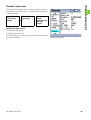
1.1 ND 2100G Overview
1.1 ND 2100G Overview
Overview
The ND 2100G is an advanced digital readout system for performing
single or multiple gage measurements at very high levels of precision
and accuracy. Dimensional inspections of components are performed
using encoders or transducers as part of in-line production activities,
or final quality inspection. Measurements are conducted under
operator control, or are semi-automated and conducted in conjunction
with a fixtured gage system.
The ND 2100G is configured at the factory to support
One, four or eight single-input channels, or
Up to 16 multiplexed RS-232 input channels, or
Combinations of single-input channels and multiplexed RS-232 input
channels for a total of up to 16 channels
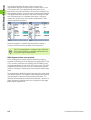
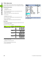
Channel inputs can be algebraically combined or processed by
powerful math and control formulas to display dimensions such as
flatness, volume and runout. Formulas are created as part of the
ND 2100G setup using straightforward screen control and math
functions.
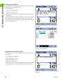
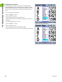
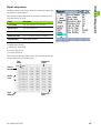
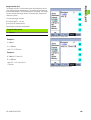
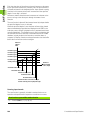
C1=28.846 mm
C2=-16.026 mm
Sum=C1+C2
Dif=C1-C2
Sum=12.820
Dif=44.872
Channel inputs are processed by formulas to display dimensions.
18
1 Operation
1.1 ND 2100G Overview
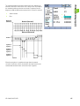
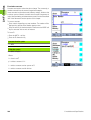
The intuitive user interface includes a large character color LCD for fast
and accurate measurement feedback. User interface screens include
a digital readout of current values, bar and dial position value
indicators, graphs of values, histograms of measurement statistics
and tables of measurement and of SPC data.
Digital readout (DRO)
Horizontal bar
Vertical bar
Dial
Graph of values
Histogram of values
Measurement data
SPC data
ND 2100G GAGE-CHEK
19
1.2 Basic operation of the ND 2100G
1.2 Basic operation of
the ND 2100G
Switching on the ND 2100G
Switch on the ND 2100G. The POWER switch is
located on the rear of the enclosure. After switching
the power on, or after a power failure, the power-up
screen will be displayed.
finish
Press the FINISH key to advance from the power-up
screen to the home screen.
Your ND 2100G is now ready for operation.
Power-up screen.
Switching off the ND 2100G
Switch the ND 2100G off. The parts, formulas and
dimensions that have been saved during operation
will be retained in memory.
20
1 Operation
1.3 Panel key descriptions
1.3 Panel key descriptions
Descriptions of panel key functions are provided in the following
pages for Command, Fast Track, Send, LCD On/Off and Arrow Cursor
keys. Soft key functions are also described later as part of LCD
screens and menus.
Command keys
enter
finish
Function
Enter data: Press the ENTER key to enter
data for a measurement. Information on the
LCD is stored as measurement or
configuration data. This information includes
current dimension values or alphanumeric
data for a configuration or user prompt data
field.
Exit a screen: Press the FINISH key to exit a
screen saving any changes that were made.
The FINISH key may also be used to return
from the display of measurement or SPC data
to the current home screen.
cancel
Delete data or features: Press the CANCEL
key to erase the last data value entered into
the system from the numeric keypad or
delete data in configuration fields.
quit
Quit current activity: Press the QUIT key to
abort the current task and return to the home
screen or to exit the current menu.
Fast Track keys
7
8
9
4
5
6
1
2
3
0
+/-
enter
finish
cancel
quit
ND 2100G Panel keys.
Function
Left frequently used function:
Press the LEFT WIDE key to initiate
the function programmed for this
key. The factory default function for
this key is RSETDYN.
Right frequently used function:
Press the RIGHT WIDE key to
initiate the function programmed for
this key. The factory default function
for this key is ENTER.
Send key
Function
Transmit measurement results: Press the
SEND key to transmit measurement data to a
computer, a USB printer or a USB memory
drive.
ND 2100G GAGE-CHEK
21
1.3 Panel key descriptions
LCD On/Off key
Function
Turn the LCD off or clear data: Press the
LCD ON/OFF key to toggle between LCD on
and LCD off, or to clear channel calibrations,
delete data stored for a single part or delete
data stored for all parts
Arrow cursor keys
Function
Navigate menus and setup screen
data fields.
Numeric keys
22
7
8
9
4
5
6
1
2
3
0
+/-
Function
The numeric keypad is used primarily
for numeric data entry. The decimal
point key and +/- key can also be used
to increase or decrease the LCD
screen contrast when a decimal point
or +/- input are not expected by the
system as part of a data entry
process. The screen contrast setting
will be saved when the system is
powered down and used as the
default contrast setting the next time
the system is turned on.
1 Operation
1.3 Panel key descriptions
Dimension keys
Dimension keys can be assigned one of six hot key functions for use
when the DRO screen is displayed. When graph, bar value and data
screens are displayed, the dimension keys are used to display values
for single dimensions or a smaller group of dimensions.
Dimension keys
Function
Pressing a dimension key in the:
DRO screen: performs the function
assigned in the hotkey setup
screen. By default no hotkey
function is assigned until the user
makes the assignment
Graph screens: displays a single
graph for the corresponding
dimension
Bar screens: Displays a single bar
showing current values for the
corresponding dimension
Data screens: displays a single data
table of stored values for the
corresponding dimension
Hot key assignments are discussed in detail on page 141.
Soft keys
Function
Soft keys initiate functions that are
labeled above the keys at the bottom
of the LCD screen. As different
system functions are selected, the
soft key labels change in support of
those functions.
ND 2100G GAGE-CHEK
Pressing the dimension A key in a graph screen
selects the A graph for display.
23
1.3 Panel key descriptions
Pressing the VIEW... soft key changes soft key labels to show five
screen viewing options, graph, histogram, bar, data and DRO.
Pressing the VIEW... soft key causes soft key labels to change,
offering five options for viewing data.
When viewing graphs of stored data, current value bars or tables of
stored data, pressing a different soft key changes to the view
indicated by the soft key label.
Pressing the DATA... soft key when viewing bars causes the
dimension data table to be displayed.
24
1 Operation
1.3 Panel key descriptions
Pressing the currently highlighted soft key alternates between singledimension and multiple-dimensions displays.
Pressing the BAR... soft key when viewing multiple-dimensions
causes the currently selected dimension to be displayed by itself.
The left most soft keys can be designated hotkeys to
provide quick access to commonly used functions when
the home screen is displayed. Hot key assignments are
discussed in detail in Chapter 2: Installation, Setup and
Specifications.
ND 2100G GAGE-CHEK
25
1.4 LCD screens and menus
1.4 LCD screens and menus
The ND 2100G LCD presents a variety of screens and menus selected
by the user to display current dimension values, pass fail test results,
dimension value graphs, statistical process control graphs and data
tables, and setup and part configuration options.
Screen navigation
ND 2100G screen navigation is straightforward. For example, to
display a bar graph of current values from the home screen, press the
MENU... soft key, then press the VIEW... soft key and then the BAR...
soft key.
Press the VIEW... soft key then the BAR... soft key.
26
1 Operation
1.4 LCD screens and menus
Home screen
The home screen is displayed after the startup screen when power is
applied to the ND 2100G, and is displayed after the FINISH key is
pressed to complete a measurement or screen evaluation.The default
home screen is the DRO, but can be reassigned to another screen in
the Display setup screen.
The assignment of the home screen is discussed in detail
in Chapter 2: Installation, Setup and Specifications.
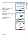
DRO screen
The DRO screen is the default home screen displayed after power is
applied and the startup screen is shown.The DRO screen provides
numeric displays of the current values of up to four dimensions. The
unit of measure, current datum and current part number or part name
are displayed in the upper right corner of the screen.
Use the arrow cursor keys to scroll dimensions when more than four
dimensions are active.
DRO screen
ND 2100G GAGE-CHEK
27
1.4 LCD screens and menus
View soft keys and screens
View soft keys for subgroups of one
Pressing the VIEW... soft key when using subgroups of one, changes
soft key labels to show five screen viewing options. Graph, histogram,
bar, data and DRO.
View soft keys
Function
GRAPH...
Displays data in a line graph
HISTO...
Displays data in a histogram
BAR...
Displays data in a bar graph
DATA...
Displays numerical data
DRO...
Displays the DRO screen
View soft keys for subgroups of one.
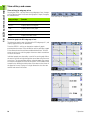
Dimension graphs for SPC subgroups of one
The dimension graph screen is displayed for SPC subgroups of 1, and
displays graphs for up to 16 dimensions.
Press the GRAPH... soft key to change the number of graphs
presented on the screen. Press a dimension soft key to display a graph
of the dimension and the minimum additional dimensions. Use the
arrow cursor keys to scroll the graphs when more data is stored than
will fit on the screen.
Individual samples are selected by a vertical line on the graph. Move
the vertical line left and right through the stored data using the arrow
cursor keys. The time and date that the selected sample was stored
are shown in the upper left corner of the screen. The ID number of the
sample for the dimension and the value of the data are also shown in
the upper left corner. Displays of a single dimension also show the
nominal and control limit values.
Vertical selection lines.
Dimension line graphs for subgroups of one.
28
1 Operation
1.4 LCD screens and menus
Dimension histograms for SPC subgroups of one
The dimension histogram screen displays histograms of values for up
to 16 dimensions. The dimension histogram screens are displayed for
SPC subgroups of one.
Press the HISTO... soft key to change the number of histograms
presented on the screen. Press a dimension soft key to display the
histogram of a single dimension.
The display of a single dimension also shows the total range and mean
of the values.
Dimension histograms for subgroups of one.
ND 2100G GAGE-CHEK
29
1.4 LCD screens and menus
Bar and dial current value displays
The bar and dial screens provide graphic displays of the current values
of up to 16 dimensions. The default bar screen can be configured to
display current value bars in horizontal or vertical orientation using the
Display setup screen.
Bar displays of multiple dimensions show current values. Bar displays
of single dimensions include the current value, nominal value, and high
and low warning and limit values.
Press the BAR... soft key to change the number of bars presented on
the screen. Press a dimension soft key to display a bar for a single
dimension.
The display can be configured in the Display setup screen to include a
dial in addition to the bars. When the dial display is also available, press
the BAR... soft key to toggle between the bars and the dial.
The display of a single dimension can be configured to be
a bar or a dial, but cannot be toggled between a single bar
and a single dial.
Bar graphs for subgroups of one.
30
1 Operation
1.4 LCD screens and menus
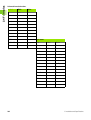
Dimension data tables for SPC subgroups of one
Dimension data screens contain measurement data stored for up to 4
dimensions. Press the DATA... soft key to toggle between views of
data for all dimensions and data for a single dimension that includes
SPC statistics.
Press a dimension soft key to display data for a single dimension. Use
the arrow cursor keys to scroll the tables when more data is stored
than will fit on the screen.
Dimension data tables for subgroups of one.
ND 2100G GAGE-CHEK
31
1.4 LCD screens and menus
View soft keys for subgroups greater than one
Pressing the VIEW... soft key, when using subgroups greater than
one, changes soft key labels to show five screen viewing options. x, r,
Bar, Data and DRO.
View soft keys
Function
x...
Displays the mean (x) of each subgroup for up
to 16 dimensions
r...
Displays the range ( r ) of each subgroup for
up to 16 dimensions
BAR...
Displays data in a bar graph
DATA...
Displays numerical data
DRO...
Displays the DRO screen
VIEW soft keys for subgroups greater than one.
Dimension x charts for subgroups greater than one
For SPC subgroups greater than 1, the dimension x screen is displayed
in place of the dimension graph screen discussed earlier. The
dimension x screen graphs the mean (x) of each subgroup for up to 16
dimensions.
Press the x... soft key to change the number of graphs presented on
the screen. Press a dimension soft key to display a graph of a single
dimension.
Use the arrow cursor keys to scroll the graphs when more data is
stored than will fit on the screen.
Individual subgroups are selected by a vertical line on the graph. Move
the vertical line left and right through the stored data using the arrow
cursor keys. The time and date when the selected subgroup data was
stored are shown in the upper left corner of the screen. The ID number
of the subgroup and the value of the data for the dimension are also
shown in the upper left corner. Displays of single dimensions also
show the control limits.
Vertical line.
x charts for subgroups greater than one.
32
1 Operation
1.4 LCD screens and menus
Dimension r charts for subgroups greater than one
For SPC subgroups greater than 1, the dimension r screen is displayed
in place of the Histogram screen discussed earlier. The dimension r
screen graphs the range ( r ) of each subgroup for up to 16 dimensions.
The range is not recalculated for each measurement, but is
recalculated each time a subgroup is completed. Refer to "SPC setup
screen" on page 91.
Use the arrow cursor keys to scroll the graphs when more data is
stored than will fit on the screen.
Individual subgroups are selected by a vertical line on the graph. Move
the vertical line left and right through the stored data using the arrow
cursor keys. The time and date when the selected subgroup data was
stored are shown in the upper left corner of the screen. The ID number
of the subgroup and the value of the data for the dimension are also
shown in the upper left corner. Displays of single dimensions also
show the range control limits.
r charts for subgroups greater than one.
ND 2100G GAGE-CHEK
33
1.4 LCD screens and menus
Dimension data tables for subgroups greater than one
Dimension data screens display measurement data for up to 4
dimensions. The Data screen for a single dimension is slightly
different for SPC subgroups greater than 1 than those for SPC
subgroups of 1. Individual subgroups are indicated by a horizontal line
in tables for single dimensions. The data table for multiple dimensions
remains unchanged for SPC subgroups greater than 1.
Press the DATA... soft key to toggle between views of data for all
dimensions and data for a single dimension that includes SPC
statistics. Press a dimension soft key to display data for a single
dimension.
Use the arrow cursor keys to scroll the tables when more data is
stored than will fit on the screen.
The time and date when the highlighted subgroup data was stored are
shown in the upper left corner of the screen. The ID number of the
data record and the value of the data for the dimension are also shown
in the upper left corner.
Dimension data tables for subgroups greater than one.
34
1 Operation
1.4 LCD screens and menus
in/mm menu items
Press the IN/MM soft key to toggle the display between inch and
millimeter units of measure. This does not alter the channel
configurations in the Channel setup screen. The ND 2100G calculates
the conversion from one unit of measure to another as a convenience
to the user.
Master menu items and screens
Master screens are used to calibrate the encoder datums or
transducer input channel ranges. The Master function is configured in
the Master setup screen to either calibrate datum D0 for encoders, or
calibrate datum D0 and the entire channel range for transducers.
Prior to applying, and after clearing a mastered channel
value, the ND 2100G machine zero is used as the absolute
datum.
Master screen for calibrating encoder datums
When the Master setup screen is configured to perform full
calibrations of transducer input channels (Master type set to MinMax), the full range of any channel input can be calibrated at any time
using the Master function Min and Max screens. Up to 18 range
calibration values can be stored for each ND 2100G transducer input
channel. Any of these groups can be quickly recalled and applied later.
Instructions for calibrating channel datums are provided
later in this chapter.
Pressing the MASTER soft key brings up the Channel
Master screen for calibrating encoder datums.
ND 2100G GAGE-CHEK
35
1.4 LCD screens and menus
Master screen for calibrating transducer ranges
When the Master setup screen is configured to perform full
calibrations of transducer input channels (Master type set to MinMax), the full range of any channel input can be calibrated at any time
using the Master function Min and Max screens. Up to 18 range
calibration values can be stored for each ND 2100G transducer input
channel. Any of these groups can be quickly recalled and applied later.
Instructions for calibrating transducer input channels Min
and Max range values are provided later in this chapter.
Master Min screen for calibrating transducer range.
Master Max screen for calibrating transducer range.
36
1 Operation
1.4 LCD screens and menus
Menu soft keys
Pressing the MENU... soft key changes soft key labels to show Menu
options: View..., in/mm, Datum..., Extra and Setup.
Menu soft keys
Function
VIEW...
Pressing the VIEW... soft key provides
access to View menu options. Refer to "View
soft keys and screens" on page 28.
IN/MM
Pressing IN/MM soft key toggles between
inch and millimeter units of measure for
applicable dimensions. Refer to "in/mm menu
items" on page 35.
DATUM...
Pressing the DATUM... soft key provides
access to Datum menu options.
EXTRA
Pressing the EXTRA soft key provides access
to Extra menu options.
SETUP
Pressing the SETUP soft key provides access
to Setup menu options.
Menu soft keys.
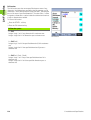
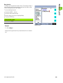
The datum menu functions
The DATUM... functions provide the means to ZERO, PRESET, CLEAR
and toggle between measurement reference datums.
Datum soft keys
Function
D0/D1
Pressing the D0/D1 soft key toggles between
the absolute datum (D0) and the incremental
datum (D1).
ZERO...
The Zero menu function can be used at any
time to simultaneously zero all incremental
datums, or to zero any specific incremental
datum.
MASTER
The Master functions are used to calibrate
the encoder datums or transducer input
channel ranges.
PRESET
The Dimension Preset screen is used to
preset incremental datums.
Datum soft keys.
The incremental datum of a dimension can be
preset to a specific value at any time by
pressing the PRESET soft key, pressing a
dimension soft key and entering the desired
value.
CLEAR
The Clear menu function can be used at any
time to simultaneously clear all incremental
datums. Cleared incremental datums (D1) are
made equal to absolute datums (D0).
ND 2100G GAGE-CHEK
37
1.4 LCD screens and menus
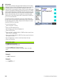
The Extra menu functions
The Extra menu provides quick access to a variety of display and other
system functions. To use any Extra menu function, highlight the
desired function, and then press the ENTER key.
Extra menu
functions
Function
Cycle
Advances to the next defined part. Part
numbers are cycled in a continuous loop.
DMS/DD
Toggles the display of angles between
Degrees, Minutes, Seconds (DMS) and
Decimal Degrees (DD).
Fast3
Refer to "Fast3" on page 39.
Hold
Toggle function that holds (freezes) or
releases the current value of a single
dimension when a dimension soft key is
pressed, or of all dimensions when the ALL
soft key is pressed.
Part?
Displays a pop-up screen that allows the user
to specify a new part number.
Rad/Dia
Toggles between the radius and diameter
measurement types on the DRO screen, if
radius or diameter was specified in the
Formats setup screen.
Recall
Applies the last used incremental datum (D1)
preset that was entered by the user.
RsetDyn
Resets the minimum and maximum values
accumulated during dynamic measurements.
This function must be initiated prior to new
dynamic measurements.
Send
Sends the specified current dimension
values, or all current dimension values to the
RS-232 serial port for transmission to a
computer. The user is prompted to send one
or all.
SendRec
Sends stored records to the RS-232 serial
port for transmission to a computer. Refer to
"Report setup screen" on page 127.
38
EXTRA menu functions.
1 Operation
1.4 LCD screens and menus
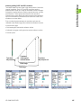
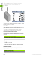
Fast3
The Fast3 function samples the channel 2 input each time the channel
1 input changes a specified sample increment. If the sampled value of
channel 2 falls outside a specified range, all base-channel (first 1, 4 or
8 channels) input values will be stored in a dedicated memory array,
otherwise samples will not be stored.
This sampling process continues until:
The user aborts the process by pressing the QUIT or the CANCEL
key
The user clears memory and restarts the process by pressing the
ENTER key
The user successfully completes the process by pressing the
FINISH key
The process is automatically completed after 50,000 sets of channel
positions have been stored
For the duration of the Fast3 function process, the
ND 2100G adopts an X-Y axis paradigm. Channel 1 is
referred to as the X-axis, and channel 2 as the Y-axis.
Channel input
values stored
High
limit
Y-Axis
(ch 2)
Channel 2
input value
Low
limit
Sample
increment
X-Axis (ch 1)
Channel input
values stored
In the example shown, the channel 2 (Y-axis) input values exceed the
user-specified limits five times, but channel input values are stored
only twice when the channel 2 value exceeds the limits at a sample
point between intervals.
ND 2100G GAGE-CHEK
39
1.4 LCD screens and menus
When the Fast3 function is successfully completed, the stored sets of
channel input values are processed by the ND 2100G dimension
formulas in the order that they were collected. The formula results are
then stored in the ND 2100G database. During the processing of
formulas, a percentage of completion will be displayed. Since up to
50,000 sets of channel input values can be collected and processed by
formulas, considerable time could be required to complete the
processing.
Since the values processed by formulas after Fast3 data
collection are contained in memory storage, no user
interaction is possible. For this reason functions that
require user interaction such as the Ask function must be
avoided in formulas when the Fast3 Extra menu function
is used.
If any key is pressed while the ND 2100G is processing
formulas, the remaining channel input values will be
deleted from memory and formula processing will be
aborted.
To access the Fast3 function:
U
Press the MENU... soft key
Press the EXTRA soft key
U Use the arrow cursor keys to highlight Fast3
U Press the ENTER key
You will then be prompted to:
U
U
U
U
U
Enter a Y axis (channel 2) upper limit
Enter a Y axis (channel 2) lower limit
Enter an X axis (channel 1) capture increment
Enter an X axis (channel 1) resolution factor (this is a multiplier of
scale resolution)
Once these parameters are entered, the Fast3 function will begin to
read the input values for channels 1 and 2.
FAST3 highlighted.
Setup menu functions
ND 2100G operating parameters and formulas that define dimension
values are entered into the system from Setup menu screens.
Setup menu functions and formulas and are discussed in
Chapter 2: Installation, Setup and Specifications
40
1 Operation
1.5 Operating instructions
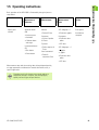
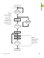
1.5 Operating instructions
Basic operation of the ND 2100G is illustrated by the typical process
steps below.
Select Part
Establish a
Measurement
Reference
Conduct a
Measurement
Review
Measurement
Data
Report or Send
Results
Specify part
number
Absolute datum
(D0)
Manual:
SPC Subgroup = 1
Print reports
• Probe & Enter
• Dimension graphs
Sequence:
Histograms
Send data to
computer
• Series of probes
& Enters
• Dimension data
tables
Dynamic:
• SPC data
• Probe samples &
Enter
SPC Subgroups > 1
• Hard stop zero
• Set datum
• Calibrate datum
and range
Incremental datum
(D1)
• Zero datum
• Preset datum
Semi-automated:
• Probe &
automatic Enter
• x graphs
• r graphs
• Dimension data
tables
• SPC data
Measurement steps and the resulting data collected depend entirely
on setup parameters and dimension formulas defined to satisfy a
specific application.
Examples used in this chapter use encoder probes to
emphasize concepts. However, the concepts apply
equally well to all types of input devices.
ND 2100G GAGE-CHEK
41
1.5 Operating instructions
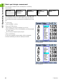
Select a part to begin a measurement
The correct part (number) must be selected prior to conducting
measurements.
Select Part
Establish a
Measurement
Reference
Conduct a
Measurement
Review
Measurement
Data
Report or Send
Results
One hundred part configurations can be stored in the ND 2100G. Each
part configuration includes all the ND 2100G settings and dimension
formulas required to conduct measurements and report results for the
part.
To select a part:
U
U
U
U
U
U
Press the MENU... soft key
Press the EXTRA soft key
Use the arrow cursor keys to highlight Cycle or Part?
Press the ENTER key. If Part? was highlighted, you will be prompted
for a part number.
Use the numeric keypad to specify the part
Press the ENTER key
If Cycle was highlighted, the part number will be incremented.
Continue incrementing to select the desired part number.
Cycle highlighted.
Part? highlighted.
42
1 Operation
1.5 Operating instructions
Establish a reference for the measurement
A measurement reference should be established prior to conducting
measurements. Measurement references can be established by
calibrating channels or presetting dimensions.
Select Part
Establish a
Measurement
Reference
Conduct a
Measurement
Review
Measurement
Data
Report or Send
Results
An input calibration is applied to any parts that use that
channel in a formula. For example, a channel calibration
performed for channel 1 and part number 0 will also apply
to any other parts using channel 1.
Calibrating channels using the Master function
Channel calibrations are performed using the Master function. A
single-point calibration defines the reference value of the absolute
datum (D0) of an input channel. A full calibration defines the reference
value of the absolute datum, and the resolution of the channel input.
Since encoders have fixed resolutions based on etched scales or
some other permanent device characteristic, typically only a single
point is calibrated to define a reference position. Transducers such as
LVDT and Half-bridge devices do not have fixed resolutions. The use
of these devices requires calibrating both ends of the transducer’s
measurement range to derive resolution. Once a full calibration has
been performed, single-point calibrations can be performed as
required to define new measurement reference positions.
ND 2100G GAGE-CHEK
43
1.5 Operating instructions
Calibration of a single reference point
A single measurement reference point can be calibrated for encoders
and fully-calibrated transducers.
The Master type should be set to Mean in the Master
setup screen to perform a calibration of a single encoder
point. Refer to "Master setup screen" on page 111.
To calibrate a single reference point
U
U
U
U
U
U
Press the MASTER soft key
Use the arrow cursor keys to select the desired channel
Position the probe against the reference surface
Use the numeric keypad to enter the reference value (zero or the
desired offset) into the Master Value data field
Press the ENTER key
Press the YES soft key to calibrate the measurement reference
Channel 1 selected. Reference value of 0.
A green dot will appear next to the actual value indicating that the
reference point is calibrated.
Press the YES soft key.
Channel 1 calibrated.
44
1 Operation
1.5 Operating instructions
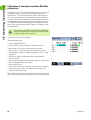
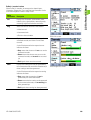
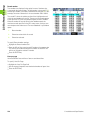
Calibration groups (G1, G2, G3...G18)
All calibration values shown on the screen are simultaneously applied
when the ENTER key is pressed. While this is acceptable in most
cases, some applications require entering a series of calibrations at
different times. The example shown here illustrates this difference.
When measuring runout at two points on a
rod, both channels are measuring a
common surface and can be calibrated
simultaneously. In this example, both
channels are calibrated to zero on the rod
surface in calibration group 1 (G1).
Completed calibrations are indicated by
filled circles at the right of the actual channel
values.
Calibrating two points on a rod.
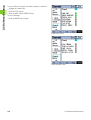
When measuring the low and high lifts of
two offset cams, simultaneous calibration
on the offset surfaces is not possible. First
one channel must be calibrated to zero on
the low surface of one cam, then after
turning the cam shaft 90 degrees, the
second channel must be calibrated to zero
on the low surface of the second cam.
The first calibration is performed in
calibration group 1 (G1), then the camshaft
is turned 90 degrees, and the second
calibration is performed in calibration group
2 (G2). By performing the calibrations in
different groups, the calibrations are made
independent. Completed calibrations are
indicated by filled circles at the right of the
actual channel values.
Calibrating offset surfaces Master G1.
Calibrating offset surfaces Master G2.
ND 2100G GAGE-CHEK
45
1.5 Operating instructions
Calibrations of transducer resolution (Min-Max
calibrations)
Transducers such as LVDT and half bridge devices do not have fixed
resolutions based on etched scales or other permanent device
characteristics. The use of these devices requires calibrating both
ends of the transducer range of measurement to derive transducer
resolution. Full transducer calibrations are performed periodically on a
schedule determined by your application using the Master function.
Full calibrations are performed only after performing the transducer
gain and null setup steps described in Chapter 2: Installation, Setup
and Specifications.
The Master type should be set to Min-Max in the Master
setup screen to perform a full transducer calibration. Refer
to "Master setup screen" on page 111.
To perform a full transducer calibration:
Calibrate minimum level:
U
U
U
U
U
U
U
U
Press the MASTER soft key
Press the MIN soft key to display the Master Min screen
Use the arrow cursor keys to select the desired channel
Press the G1, G2...G18 soft key to select a group to store the
calibration data in. Refer to "Calibration groups (G1, G2, G3...G18)"
on page 45.
Position the channel’s probe against the measurement Min
reference surface
Use the numeric keypad to enter the Min reference value into the
Master Value data field for the channel
Press the ENTER key
Press the YES soft key to set the Min value or offset the absolute
datum (D0) for the channel. This calibrates the low end of the
channel measurement range.
Completed minimum level calibration.
The completed minimum level calibration will be indicated by a filled
green circle in the Mn column at the right of the Actual channel value.
46
1 Operation
1.5 Operating instructions
Calibrate maximum level:
U
U
U
U
U
U
Press the MAX soft key
Use the arrow cursor keys to select the same channel as in step 1
if necessary
Position the channel probe against the measurement Max reference
surface for the maximum end of the channel calibration range
Use the numeric keypad to enter the Max value into the Master
Value data field for the channel
Press the ENTER key
Press the YES soft key to calibrate the maximum value for the
channel input
The completed maximum level calibration will be indicated by a filled
green circle in the Mx column at the right of the Actual channel value.
Completed maximum level calibration.
ND 2100G GAGE-CHEK
47
1.5 Operating instructions
Establishing a temporary dimension reference
Establishing a temporary dimension reference is useful when quick
point to point measurements are desired. The temporary reference is
only applied to the associated dimension, and only to the current part.
For example, a temporary reference established for dimension A and
part number 0 will not apply to any dimensions or to any other parts
that might include their own dimension A.
Temporary dimension references can be established for encoders and
transducers. Since only one point is used as a reference, transducer
resolution remains unchanged.
Dimension references can be zeroed or preset to specific values.
Zeroing a dimension reference
Dimensions can be zeroed at any time using the Datum/Zero function.
The zero reference is temporary in the sense that it uses the
incremental datum D1, and has no effect on the absolute datum D0.
To zero a dimension:
U
U
U
U
U
Press the MENU... soft key
Press the DATUM soft key
Press the ZERO... soft key. The soft keys across the bottom of the
screen will be labeled to support zeroing specific or all dimensions.
Use the left and right arrow cursor keys to scroll through dimensions
when there are more dimensions defined than ND 2100G soft keys
Press the desired ZERO key to zero the corresponding dimension
Dimension A prior to zeroing.
Dimension A zeroed.
48
1 Operation
1.5 Operating instructions
Presetting a dimension reference to a specific value
Dimensions can be preset to a user-specified value using the Datum/
Preset function. The reference is temporary in the sense that it uses
the incremental datum D1, and has no effect on the absolute datum
D0.
To preset a dimension reference:
U
U
U
U
U
U
U
Press the MENU... soft key
Press the DATUM soft key
Press the PRESET soft key. The Select dimensions screen will be
displayed.
Press the dimension key associated with the dimension you wish to
preset. A text line will be displayed
Use the numeric keypad to enter the reference value (preset) of the
new reference
If desired, press the W/NOM soft key to change the nominal value
in the Tolerance setup screen to the new preset reference value
Press the ENTER key to preset the dimension measurement
reference
Dimension preset text line.
Enter the reference value.
Dimension A preset.
ND 2100G GAGE-CHEK
49
1.5 Operating instructions
Clearing channel calibrations
The reference calibrations and full calibrations of all channels can be
cleared using the LCD ON/OFF key.
To clear calibrations:
U
U
U
Press the LCD ON/OFF key
Press the CLR CAL soft key
Press the YES soft key to clear channel mastered values and full
calibrations
Channel mastered values and full calibrations will be cleared, indicated
by the empty circles at the right of the screen. The values will be
retained in the Master values fields, and can be reactivated at any time
by pressing the ENTER key.
Press the YES soft key to confirm clearing channel
calibrations.
Empty circles indicate channel mastered values and
full calibrations are cleared.
Clearing dimension references (presets)
Dimension references can be cleared at any time using the Datum/
Clear function.
To clear dimension references:
U
U
U
U
Press the MENU... soft key
Press the DATUM soft key
Press the CLEAR soft key
Press the YES soft key to clear dimension preset references. When
a preset reference is cleared, D0 becomes the new reference.
Press the YES soft key to confirm clearing dimension
references.
50
1 Operation
1.5 Operating instructions
Conducting measurements
Once a part number is selected and a reference is established,
measurements can be conducted.
Select Part
Establish a
Measurement
Reference
Conduct a
Measurement
Review
Measurement
Data
Report or Send
Results
Measurements can:
Be conducted manually, completely under the control of the
operator
Follow a predetermined sequence of steps shown on the screen
Be based on dynamic samples of changing input data
Be semi-automated to increase the throughput of repetitive
measurements
Typically a setup person will configure the ND 2100G for operation in
the Setup screens and then will construct formulas defining
dimensions in the Formula screens described in Chapter 2:
Installation, Setup and Specifications.
Once the ND 2100G is configured and dimension formulas are
constructed, measurement instructions are usually given to the
operator that reflect the specific measurement requirements and gage
equipment setup. Instructions provided in this guide are generic and
meant to be used as guidelines when applying the ND 2100G to
specific measuring applications.
Manual measurements
Manual measurements are performed completely under the control of
an operator. Measurement results can be displayed as current values,
in graphs or in data tables using the screens described earlier in this
chapter. Please refer to the descriptions of Views on page 28.
Measurements can also be printed or transmitted to a computer. The
data printed or transmitted are specified and formatted in the setup
screens described in Chapter 2: Installation, Setup and Specifications.
To conduct manual measurements:
U
Probe a single point with one channel, or multiple points
simultaneously with multiple channels
U
When the measurement data are displayed on the LCD, press the
ENTER key to store the data
ND 2100G GAGE-CHEK
51
1.5 Operating instructions
Sequential measurements
The ND 2100G can be configured in the Formula setup screen to direct
the user through a sequence of predetermined measurement steps.
Typically a setup person will provide instructions describing how to
conduct the measurements. However, the ND 2100G operation is
fundamentally the same for all sequential measurements.
Measurement results can be displayed as current values, in graphs or
in data tables using the screens described earlier in this chapter.
Please refer to the descriptions of Views on page 28.
Measurements results can also be printed or transmitted to a
computer. The data printed or transmitted are specified and formatted
in the setup screens described in Chapter 2: Installation, Setup and
Specifications.
To perform a sequential measurement:
U
U
U
Probe the dimension underlined on the DRO screen
Press the ENTER key to store the data. The underline will advance
to highlight the next dimension in the measurement sequence.
Continue probing the underlined dimensions and pressing the
ENTER key, following the sequence of underlined steps on the LCD
When measurements specified for the part are complete, the
ND 2100G will return to underline the first dimension in the series to
indicate the beginning of a new sequence.
Press the ENTER key to store data and advance to
next dimension.
52
1 Operation
1.5 Operating instructions
Dynamically sampled measurements
The ND 2100G can be configured in the Formula setup screen to
sample input channels and retain the minimum and maximum values
of all samples for each channel. Typically a setup person specifies
dynamic measurements to evaluate rotational or curved surfaces and
will provide instructions describing how to conduct the
measurements. The ND 2100G operation is essentially the same for
all dynamic measurements.
Measurement results can be displayed as current values, in graphs or
in data tables using the screens described earlier in this chapter.
Please refer to the descriptions of Views on page 28.
Measurement results can also be printed or transmitted to a
computer. The data printed or transmitted is specified and formatted
in the setup screens described in Chapter 2: Installation, Setup and
Specifications.
In the example shown here, the runout of a shaft is measured. The
minimum and maximum values are sampled as the shaft is turned.
To perform a dynamic measurement:
U
U
U
U
Perform a dynamic reset by pressing the LEFT WIDE key (factory
default), or by highlighting RsetDyn in the Extra menu
Press the ENTER key to clear old dynamic measurement data prior
to a new measurement
Position the probe(s) against the surface to be measured
Rotate or move the surface slowly while observing the resulting
dimension value(s)
Measuring the runout of a shaft.
The sampling rate for LVDT, HBT (Half-bridge) and serial
transducers will be slower than for encoders. If your
system includes these input devices, the part must be
rotated or moved slowly to ensure that all points on the
surface are sampled.
U
U
Repeat the rotation or movement until the dimension values that
reflect minimum or maximum values no longer change
Press the ENTER key to store the measurement data
ND 2100G GAGE-CHEK
53
1.5 Operating instructions
Semi-automated measurements
Normally, measurements shown on the DRO screen are not stored in
the ND 2100G database until the user presses the ENTER key.
However, the ND 2100G can be configured in the Formula setup
screen to perform and store measurements automatically when the
gage is loaded with a new part.
Measurement results can also be printed or transmitted to a
computer. The data printed or transmitted is specified and formatted
in the setup screens described in Chapter 2: Installation, Setup and
Specifications.
In the example shown here, the flatness of a sheet is measured. The
measurement is performed and entered into the database a short time
after the gage is lowered to position the probes against the surface of
the sheet. The channels are reset for a new measurement when the
probes are lifted away from the sheet.
Load part: Channels ready
Typically, a setup person specifies semi-automated measurements to
increase the throughput of repetitive measurements, and will provide
instructions describing how to conduct the measurements, and load
and unload the gage.
Measurement results can be displayed as current values, in graphs or
in data tables using the screens described earlier in this chapter.
Please refer to the descriptions of Views on page 28.
The instructions for performing semi-automated measurements
depend entirely on the measurement application and equipment
setup, and must be provided by the setup person. Refer to "Trip
function and measurement automation" on page 212 for more details
regarding semi-automated measurements.
Gage closed: Channels measure
Unload part: Channels reset
54
1 Operation
1.5 Operating instructions
Reviewing measurements
Measurement results can be reviewed in graphs or in data tables using
the screens described earlier in this chapter. Please refer to the
descriptions of Views on page 28.
Select Part
Establish a
Measurement
Reference
Conduct a
Measurement
Review
Measurement
Data
Report or Send
Results
Review
Measurement
Data
Report or Send
Results
Printing reports or sending results to a computer
Measurement data can be printed or transmitted to a computer. The
report and data transmission formats are prepared in the Header,
Report, Send, Parallel and RS-232 setup screens described in Chapter
2: Installation, Setup and Specifications.
Select Part
Establish a
Measurement
Reference
Conduct a
Measurement
Printing reports
Reports of current dimension values, stored measurement results or
ND 2100G setup parameters can be printed by displaying the desired
screen and pressing the PRINT key. In some cases, the user will be
prompted to provide additional information.
ND 2100G GAGE-CHEK
55
1.5 Operating instructions
Sending data to a computer
Current dimension values, or a collection of stored dimension
measurement results can be transmitted to a computer using the
Send and SendRec functions in the Extra menu. Refer to "The Extra
menu functions" on page 38 for more details regarding the Extra
menu.
To send current dimension values:
U
Press the MENU... soft key
Press the EXTRA soft key
U Use the arrow cursor keys to highlight Send
U Press the ENTER key to send the current dimension values to a
computer
To send stored measurement results:
U
U
U
U
U
Press the MENU... soft key
Press the EXTRA soft key
Use the arrow cursor keys to highlight SendRec
Press the ENTER key to send a file of stored measurement results
Use Send to send current values.
Use SendRec to send stored measurement values.
56
1 Operation
1.5 Operating instructions
Data reports
Report type
Screen
User actions
Current dimensions (Numeric display)
DRO
U
Press PRINT key
Graphs of dimension values
(SPC subgroups = 1)
Graph...
U
Press PRINT key
Histograms of dimension values
(SPC subgroups = 1)
Histo...
U
Press PRINT key
x chart of subgroup mean values
(SPC subgroups> 1)
x chart
U
Press PRINT key
r chart of subgroup range values
(SPC subgroups>1)
r chart
U
Press PRINT key
Current dimension values (Bar display)
Bar...
U
Press PRINT key
Current dimension values (Dial display)
Dial...
U
Press PRINT key
Data table multiple-dimensions
Data...
U
Press PRINT key
U
Respond to prompt
U
Press DIMENSION soft key
U
Press PRINT key
U
Respond to prompt
Data table single-dimensions
ND 2100G GAGE-CHEK
Data...
57
1.5 Operating instructions
Clearing stored measurement data
Stored measurement data can be cleared for a single part, or for all
parts by pressing the LCD ON/OFF key.
Erased data cannot be restored.
To clear stored data for a single part:
U
U
U
Select the desired part
Press the LCD ON/OFF key
Press the CLR PRT soft key
Stored data for the selected part will be erased.
To clear stored data for all parts:
U
U
U
Select the desired part
Press the LCD ON/OFF key
Press the CLR ALL soft key
Stored data for all parts will be erased.
58
1 Operation
Installation, Setup,
Formulas and
Specifications
2.1 ND 2100G Shipment Contents
2.1 ND 2100G Shipment Contents
The contents of your ND 2100G shipment are described below.
Repackaging instructions are also included for return shipments for
distributors and OEM customers that are configuring an ND 2100G
and shipping it to an end-user.
Save the ND 2100G packaging materials for possible
return shipment or shipment to an end user.
Items included with the ND 2100G
The following items are shipped with the ND 2100G:
ND 2100G instrument
Mounting stand hardware
Power cord
ND 2100G Quick Reference Guide
Warranty registration card
Optional items possibly included
The following items might be shipped with your ND 2100G, depending
on the options and accessories ordered at the time of purchase:
Remote foot switch
Remote keypad
ND 2100G Protective cover
QUADRA-CHEK Wedge communication software
If any components were damaged in shipment, save the
packaging materials for inspection and contact your
shipping agent for mediation. Contact your HEIDENHAIN
distributor or OEM for replacement parts.
60
2 Installation and Specifications
2.1 ND 2100G Shipment Contents
Repackaging the ND 2100G
When shipping the ND 2100G on to an end-user, repackage all
ND 2100G components in the original packaging as received from the
factory.
The original packaging must be duplicated and the LCD
must be inserted face-up to prevent damage to the
screen.
It is not necessary to ship the mounting stand and
hardware with the instrument when returning the
ND 2100G for service.
Connect the mounting screws and washer to the ND 2100G
instrument
Replace the contents of the cardboard box insert if shipping the
ND 2100G on to an end-user. The cardboard box can be empty if
returning the ND 2100G to the factory for service.
Repackage the instrument, foam and cardboard box insert as
originally shipped from the factory. The instrument should be
oriented face-up in the carton.
Replace the warranty card and slip sheets originally found at the top
of the carton when shipping on to an end-user. The “Before you
begin” slip sheet should be inserted last.
ND 2100G GAGE-CHEK
61
2.2 Hardware Installation
2.2 Hardware Installation
The ND 2100G is easy to install in a variety of measurement
applications. This section describes how to install the ND 2100G
hardware.
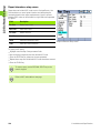
Assembling the mounting stand
The ND 2100G is secured to the swivel slots of the mounting stand by
a shoulder screw, a cap screw and associated washers.
To assemble the ND 2100G to the mounting stand as shown, and then
tighten the cap screw (5) and washers (3 & 4) so that the ND 2100G
will be secure when adjusted to the desired tilt position.
U
U
U
Tighten the shoulder screw (1)
Tighten the cap screw (5) and washers (3 & 4) so that the ND 2100G
will be secure when adjusted to the desired tilt position
Adjust the ND 2100G to the desired tilt position
Benchtop location and mounting
Rest the ND 2100G on a flat, stable surface, or bolt it to a stable
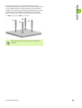
surface from the bottom using four 10/32 screws fastened in the
pattern shown at the right.
1
2
5
4
3
The dimensions are shown in millimeters.
Mounting stand assembly.
Mounting hole pattern.
62
2 Installation and Specifications
2.2 Hardware Installation
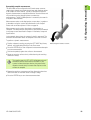
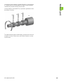
Arm mounting (optional)
Secure the arm mount adapter to the ND 2100G and bolt the adapter
and ND 2100G to the arm as shown at the right.
Optional arm mounting.
ND 2100G GAGE-CHEK
63
2.2 Hardware Installation
Connecting power
Connect the ND 2100G to power through a high-quality power surge
suppressor. Surge suppressors limit the amplitude of potentially
damaging power line transients caused by electrical machinery or
lightning, and protect the ND 2100G from most power line transients
that can corrupt system memory or damage circuits.
Do not locate the power cord where it can be walked on or will create
a tripping hazard. Connect the 3-wire power plug to only a 3-wire
grounded power outlet.
Never connect 2-wire to 3-wire adapters to the power cord
or remove the third ground wire to fit the plug into a 2-wire
electrical outlet. Modifying or overriding the third-wire
ground creates a safety hazard and should not be
permitted.
1
1
2
3
Power switch, fuse and connector.
The power connector assembly includes:
1
2
3
Power switch
Fuse compartment
Power cord connector
Always disconnect the power cord from the source of AC
power before unplugging it from the ND 2100G power
connector. The AC voltage available at electrical outlets is
extremely dangerous and can cause serious injury or
death.
64
2 Installation and Specifications
2.2 Hardware Installation
Connecting channel inputs
Channel input devices are attached to standard interface connectors
or to the RS-232 port on the rear of the ND 2100G. Many device
interfaces are available to match the wide variety of encoder and
transducer devices that can be used with the ND 2100G. The number
and type of channel input connectors will vary depending on the
application. Four standard interface connectors are shown here as
examples.
1
Channel input connections
1
Connect the channel input devices tightly to their connectors. A
channel number is provided near each connector.
Channel input devices must be configured using the Channels setup
screen. Refer to "Channels setup screen" on page 99
Systems can be configured at the factory to support a combination of
single-channel and multi-channel RS-232 networked input devices.
Channel input connectors.
These configurations can include one of the following:
1, 4 or 8 single-input channels
Up to 16 networked RS-232 input channels
A combination of single-input channels and networked RS-232 input
channels for a total of up to 16 channels
To connect channel input cables:
U
U
Verify that the ND 2100G is off
Connect the channel inputs tightly to their connectors. If the
connectors include mounting screws, do not overtighten them.
ND 2100G GAGE-CHEK
65
2.2 Hardware Installation
Connecting a computer
Measurement result data can be sent to a computer over the RS-232
port (1) using a serial cable that does not include crossed wires.
To connect a computer:
U
U
U
Verify that the ND 2100G and the computer power are off
Connect a computer COM port to the ND 2100G RS-232 serial port
(1) using a standard straight-through serial cable. Make sure the
cable connectors are tight, but do not overtighten the connector
screws.
Apply power to the computer, and then the ND 2100G. The
ND 2100G default settings for communication over the RS-232
serial port (1) are:
Baud rate
Word length
Stop bits
Parity
U
115,200
8 bits
1 bit
None
1
RS-232 connector.
Launch the computer application that will be used to communicate
with the ND 2100G, and configure the communication properties of
the COM port to match those of the ND 2100G
Connecting headphones and USB printer
Connecting headphones
Audio alerts can be sent to headphones in areas that are noisy and
make it difficult to hear, or are quiet where audio alerts might create a
disturbance.
The speaker jack (1) is located on the side of the ND 2100G.
To connect headphones:
U
U
Verify that the ND 2100G power is off. Plug the headphones into the
speaker jack (1) on the side of the enclosure.
Make sure the headphone plug is fully inserted
1
2
Connecting a USB printer
The ND 2100G supports certain USB printers. Printer models are
specified by HEIDENHAIN at the time of purchase, or approved by
HEIDENHAIN later.
The USB port (2) is located on the side of the ND 2100G.
To connect the USB printer:
U
U
Verify that the ND 2100G and printer power are off. Connect the
USB printer to the USB Type A port (2) on the side of the enclosure.
Make sure the USB cable plug is fully inserted
66
Headphone and USB connectors.
2 Installation and Specifications
2.2 Hardware Installation
Connecting an optional foot switch or remote
keypad
The optional foot switch and remote keypad are connected to the
RJ-45 connector (1) on the side of the ND 2100G.
Often, only the optional foot switch or remote keypad is used.
However, two options can be connected simultaneously using a RJ-45
splitter (2).
RJ-45 splitters are available from most retail electronics
stores.
The foot switch and remote keypad can be used individually or in
combination:
foot switch
1
foot switch and remote keypad
When the foot switch and remote keypad are connected using the
RJ-45 splitter (2), all operating functions of each device are retained.
However, the switch shares Hot Key mapping with the number keys
7 and 8 of the remote keypad. As a result, functions assigned to the
two switch contacts will also be mapped to remote keypad numbers
7 and 8.
2
RJ-45 connector and RJ-45 splitter.
Refer to "Hot Keys setup screen" on page 141.
To connect the foot switch or remote keypad:
U
U
U
Verify that the ND 2100G is off
Plug an RJ-45 splitter (2) into the ND 2100G RJ-45 connector (1) if
multiple devices will be used
Connect the RJ-45 plug of the devices into the RJ-45 splitter (2) if
multiple devices will be used, or directly into the ND 2100G RJ-45
connector (1) if only a single device will be used
Optional foot switch and remote keypad.
ND 2100G GAGE-CHEK
67
2.3 Software setup
2.3 Software setup
The operating parameters of the ND 2100G must be configured prior
to using the system for the first time, and any time part measurement,
reporting or communication requirements change. Day to day use of
the ND 2100G does not require reconfiguration of system settings.
Parameter changes made in any of the setup screens can
change the operation of the ND 2100G. For this reason
critical setup parameters are password protected. Only
qualified personnel should be given password access to
setup screen parameters. Refer to "Supervisor setup
screen" on page 161 for unlocking of password protected
setup functions.
Software can be configured manually using the Setup menu screens,
or automatically by loading a settings file saved after a previous setup
session. Settings files are loaded from USB drives.
Parameters configured in setup screens will be retained until:
The data-backup battery is changed
The data and settings are cleared by maintenance personnel
Parameters are changed using the Setup menu screens
Certain software upgrades are performed
Previously saved settings files are loaded
68
2 Installation and Specifications
2.3 Software setup
Setup menu
Most operating parameters of the ND 2100G are configured using
screens and data fields accessed from the Setup menu. Highlighting
Setup menu items (1) on the left side of the setup screen displays the
corresponding setup parameter data fields (3) and choice fields(2) on
the right side of the screen.
Setup menu features:
1
2
3
2
1
3
Setup menu item: Setup screen name
Setup choice field: Setup choices are made
Setup data field: Setup data are entered
Setup screen menu items, data fields and choice
fields.
ND 2100G GAGE-CHEK
69
2.3 Software setup
Accessing and navigating the Setup menu
To access the Setup menu:
U
U
Press the MENU... soft key
Press the SETUP soft key. The Setup menu is displayed.
Press the MENU... soft key then press the SETUP soft key to display the Setup menu.
To navigate the Setup menu:
U
U
U
Use the up and DOWN ARROW cursor keys to scroll through the
Setup menu screens
Use the RIGHT ARROW cursor key to access setup screen menu
items
Use the UP and DOWN ARROW cursor keys to scroll through and
select a menu item
Pressing the DOWN ARROW cursor highlights next menu item, then pressing the RIGHT ARROW cursor highlights top screen
parameter.
70
2 Installation and Specifications
Setup mode function
1
Menu top
2
Page up
3
Page down
4
Menu bottom
2.3 Software setup
Using dimension keys in the setup mode
The functions of the dimension keys change to speed setup screen
navigation when the Setup menu is displayed. Dimension keys can be
used to move to the top or bottom of the Setup menu or to page up
or down through the Setup menu as shown here.
1
2
3
4
Dimension keys.
Entering data into setup fields
Enter numbers into the highlighted setup screen fields using the
numeric keypad.
Highlight a setup field and use the numeric keypad to enter a number.
The Alpha Entry screen will be displayed when alpha character entry
is required. Enter alpha characters into the Alpha Entry screen by
highlighting a letter and then pressing the ENTER key. Once all desired
characters have been entered press the FINISH key to complete the
entry.
Highlight a character then press the ENTER key to enter the character.
ND 2100G GAGE-CHEK
71
2.3 Software setup
Deleting data entries
Press the CANCEL key to erase the last (right-most) numeric digit or
alpha character in the selected data field.
Highlight a data field and press the CANCEL key to erase the right-most digit or
character.
Entering setup parameters
Setup parameters and functions are displayed above the soft keys
across the bottom of the screen.
Changing the channel or dimension number
Often setup parameters and functions are related to specific channels
or dimensions. When a channel or dimension is highlighted on the
setup screen, the channel or dimension number can be increased or
decreased by pressing the INC or DEC soft key or by pressing the
LEFT or RIGHT WIDE key.
Key
Function
1
LEFT WIDE key
Decreases the channel or dimension.
2
RIGHT WIDE key
Increases the channel or dimension.
3
DEC soft key
Decreases the channel or dimension.
4
INC soft key
Increases the channel or dimension.
1
3
72
2
4
2 Installation and Specifications
2.3 Software setup
Entering parameters
When a setup parameter field (1) is highlighted, setup alternatives are
shown above the soft keys across the bottom of the screen (2). Press
the soft key under the desired setup alternative to enter the
parameter.
Parameters and options are shown here:
1
2
Highlighted parameter field
Parameter alternatives
1
2
Copying parameters to other parts, dimensions or channels
A single highlighted parameter or all parameters of the current part,
dimension or channel can be copied to all others by pressing the
APPLY ALL soft key.
If all part, dimension or channel parameters are already the same for
the selected setup category, the APPLY ALL soft key will be grayedout.
Copy all parameters by pressing the
APPLY ALL soft key when the part,
dimension or channel name is
highlighted.
ND 2100G GAGE-CHEK
Copy a single parameter by pressing the
APPLY ALL soft key when only a single
parameter is highlighted.
73
2.3 Software setup
Saving a parameter and advancing to the next
Press the ENTER key to save the highlighted value and advance to the
next parameter.
Press the ENTER key to store the highlighted value and advance to the next
parameter.
Saving a parameter and returning to the Setup menu
Press the FINISH key to store the value and return to the Setup menu.
Press the FINISH key to store the highlighted value and return to the Setup menu.
Discarding changes and returning to the Setup menu
Press the QUIT key to return to the Setup menu on the left half of the
screen without saving changes.
Press the QUIT key to discard changes and return to the Setup menu.
74
2 Installation and Specifications
2.3 Software setup
Leaving the Setup menu
Press the FINISH key repeatedly to conclude the setup session and
return to the home screen.
Press the FINISH key repeatedly to leave the Setup menu and return to the home
screen.
Printing ND 2100G setup configurations
Print all ND 2100G configuration settings and formulas as a text file by
pressing the PRINT key while displaying any setup screen.
Saving or loading ND 2100G configurations
Insert a USB drive into the USB port, navigate to the Supervisor setup
screen, highlight the Password field and enter the password if
necessary. Press the SAVEX soft key to save the current configuration
as an .xml file, or press the LOADX soft key to load a previously saved
.xml configuration file from the USB drive.
ND 2100G GAGE-CHEK
75
2.3 Software setup
Minimum setup requirements
The minimum setup steps required to begin conducting
measurements are diagrammed below. Additional setup will be
required to utilize the full SPC, reporting, data communication and
other capabilities of the ND 2100G system. The screens required for
the initial setup are described in the remainder of this chapter.
Enter
supervisor
password
Configure
input
channels
Assign part &
dimension
labels
Configure
display of data
Specify
display
resolution
Create
dimension
formulas
Supervisor
setup screen
Channels
setup screen
Dimensions
setup screen
Display
setup screen
Formats
setup screen
Formulas
setup screen
Setup screens
Setup screen descriptions are presented in the order of their
appearance in the setup menu. However, the first time the ND 2100G
is configured the order of setup screen use should follow the essential
setup requirements diagram, and then continue in the order that best
satisfies the application or the user’s preferences. The subsequent
use of setup screens will probably be infrequent and will address
application requirements or hardware changes.
About setup screen
The About setup screen contains selections for changing the language
of text displayed on the LCD, included in transmitted data and printed
on reports. Software and hardware version information and the
number of input channels are displayed on the bottom of the screen.
To specify the displayed language:
U
U
U
Highlight the desired language
Press the YES soft key to select the language
Press the FINISH key
About setup screen.
76
2 Installation and Specifications
2.3 Software setup
Dimensions setup screen
The Dimensions setup screen contains fields for defining the part and
dimension labels displayed on the screen, included in transmitted
data, printed on reports and stored in the ND 2100G database for up
to 100 individual parts. Dimensions must be defined prior to other
setup activities and conducting tests.
Part numbers consist of up to 2 numeric digits in the range from 0 to
99 entered by the system in sequence as new parts are added. Part
and dimension labels consist of up to 8 alphanumeric characters
entered from the character entry screen and the numeric keypad. Part
names are shown in reports, but only part numbers are shown in
formulas. Completed dimension labels of one part can be copied and
applied to another.
Deleting part numbers will erase any data associated with
the part’s dimensions in the ND 2100G database. Deleting
a part number also decrements the part numbers of any
higher numbered parts. This will cause data for a part
number to be different as it now contain data from a
previously higher numbered part.
Dimensions setup screen.
Creating part numbers
Up to 100 (software) parts can be created in the ND 2100G. Multiple
parts are useful when the number of measurements performed on
one physical part is large and could be divided into categories, or when
different physical parts must be measured.
To create a new part number:
U
U
Highlight the Part field
Press the NEW soft key
Selecting part numbers
To select an existing part number:
U
Press the LEFT WIDE key or the DEC soft key to navigate down
through a list of parts
or
U
Press the RIGHT WIDE key or the INC soft key to navigate up
through a list of parts
ND 2100G GAGE-CHEK
77
2.3 Software setup
Labeling parts and dimensions
Part labels contain up to 8 alpha numeric characters. Dimension labels
contain up to 3 alpha numeric characters. Alpha numeric characters
are in the range from A to Z and can be upper or lower case. Numeric
characters are in the range from 0 to 9. The order of alpha and numeric
characters in a label is defined by the user. The process of labeling a
part or dimension is identical.
To label a part or dimension:
U
U
U
U
Highlight the Name field or a Dimension field
Press the LABEL soft key. The Alpha Entry screen is displayed.
Create the desired label using the Alpha Entry screen and/or the
numeric keypad
Press the FINISH key
Labels should be meaningful by reflecting the
measurement application when possible.
Defining visible and hidden dimensions
Dimensions are defined as visible by default, displayed on the screen
and stored in the database. Dimensions can also be defined as hidden
for use in performing operations and not displayed. Hidden
dimensions are not printed on reports or sent to computers as data
files. Visible and hidden dimensions use the same naming convention.
To create a visible dimension:
U
U
U
U
U
Highlight a dimension field
Press the VISIBLE soft key. Visible dimensions are displayed.
Press the LABEL soft key
Create a label using the Alpha Entry screen and/or the numeric
keypad
Press the FINISH key
To create a hidden dimension:
U
U
U
U
U
Highlight a dimension
Press the HIDDEN soft key. Hidden dimensions are displayed.
Press the LABEL soft key
Create a label using the Alpha Entry screen and/or the numeric
keypad
Press the FINISH key
More details regarding the use of hidden dimensions are
contained in the Formulas section of this chapter on page
163.
78
2 Installation and Specifications
2.3 Software setup
Copying dimension parameters to other parts
Dimensions assigned to one part can be copied to another to save
setup time when similar or identical measurements must be
performed on new parts.
To copy dimensions to a new part:
U
U
U
U
Highlight the Part field
Press the COPY TO soft key. The labels, formulas and all other
parameters will be copied to the next new part. Database records
will not be copied. A pop-up screen will show the next part number.
Press the OK soft key to copy the labels
Press the OK soft key to return to the Dimension setup screen
Deleting parts
Parts can be deleted when it is no longer necessary to store old
measurement results in the ND 2100G. Deleting old part data makes
more system memory available for new data and dimension formulas.
To delete a part:
U
U
U
U
Highlight the Part field
Press the INC or DEC soft key to select the desired part
Press the DEL soft key
Press the YES soft key to delete the part
ND 2100G GAGE-CHEK
79
2.3 Software setup
Formats setup screen
The Formats setup screen contains fields for specifying the display
format and display resolution for dimensions of the currently selected
part. Selections of radius and diameter measurement types are also
provided.
Specifying a dimension
U Highlight the Dimension field
U Press the DEC or INC soft key to select the desired dimension
U Press the ENTER key
Specifying radius or diameter
Radius or diameter measurements can be specified for cylindrical and
spherical parts or parts with curved surfaces. When radius or diameter
measurements are specified, the corresponding symbol will be
displayed near the associated dimension on the DRO screen.
Formats setup screen.
The display can be toggled between Radius and Diameter later from
the Home screen using the Extra menu. Toggling the display mode
changes it until the system power is cycled off and then on again. The
default display mode upon powering the ND 2100G is specified in the
Formats setup screen.
To specify radius or diameter:
U
U
U
Highlight the Rad/Dia Type field
Press the RADIUS or DIAM. soft key to specify a radius or diameter
measurement type
Press the ENTER key
80
2 Installation and Specifications
2.3 Software setup
Display resolution
The display resolution fields are used to specify how numbers are
shown on the DRO screen. Displayed numbers will be rounded as the
display resolution is decreased. This table illustrates how the display
of numbers is governed by the display resolution setting.
Channel input
Display resolution
Number displayed
1.567
0.0001
1.5670
1.567
0.001
1.567
1.567
0.01
1.57
1.567
0.1
1.6
1.567
1
2
Measurement resolution should not be higher than the
input channel resolution. Specifying display resolutions
that are higher than the channel resolutions can lead to
misleading displays of dimension values.
To specify a display resolution:
U
U
U
Highlight a display resolution (Disp Res) field
Using the numeric keypad, enter the desired display resolution
Press the ENTER key
ND 2100G GAGE-CHEK
81
2.3 Software setup
Formulas setup screen
The ND 2100G uses formulas to define and display dimensions based
on channel inputs.
These formulas are constructed by the user to display:
One dimension based on one channel
ex. A=C1
One dimension based on multiple channels
ex. A=C1+C2
Multiple dimensions based on one channel
ex. A=C1
B=2*pi*C1
Multiple dimensions based on multiple channels
ex. A=C1
B=C2
C=C1*C2
Formulas setup screen.
Formulas can be constructed that display a channel as a dimension, or
that calculate a dimension from one or more channels using powerful
math, logic or other functions.
Dimension formulas are unique to the part they are created in. For
example, a dimension formula created in part 0 cannot be used in part
2. However, system dimensions are described later in this chapter and
can be used across all parts.
Refer to "Formulas" on page 163.
82
2 Installation and Specifications
2.3 Software setup
Variables setup screen
Formulas use variables as symbols or names that represent values.
For example, in the expression:
C1+Var1()
Var1() is a variable, its value is flexible and is determined by operations
on a different formula line for the current part. Variables can represent
numeric constants, channel input values, dimension values or the
results of a wide variety of math operations.
Variables are important in formula creation because they enable users
to create flexible formulas. Rather than including data directly into a
formula, a user can use variables to represent the data. Then, when
the formula is executed, the variables are replaced with actual data.
This makes it possible for the same formula to process different sets
of data as conditions change.
The Variables setup screen allows the user to see the current value of
any of the 20 possible variables. Variables that are not defined
elsewhere by formulas can be set to constant values in this screen by
highlighting a variable field and entering the value. Variables that are
defined by formulas cannot be changed in the Variable setup screen.
Variables setup screen.
Variables are unique to the part they were created in. For example, a
variable created in part 0 cannot be used in part 2. Global variables,
discussed later in this chapter, can be used across all parts.
Variable functions are defined in the Formula setup screen
on page 82. Formulas are explained in the Formulas
section on page 163.
ND 2100G GAGE-CHEK
83
2.3 Software setup
Tolerances setup screen
The tolerances setup screen contains fields for specifying nominal
values, upper/lower warnings, upper/lower limits and minimum/
maximum bar graph levels for each dimension. An audio alert can also
be specified for warnings, limits, or both.
Tolerance ranges are indicated numerically and by bands of color on
the Current Value bar and dial screens.
The default bar and dial displays show Pass values in green, Warning
values in yellow, and Fail values in red.
These pass, warning and fail levels are shown in the bar graph of
current values to the right, and explained in the table below:
Tolerance
Description
Pass
Above low warning and below high warning. Pass
values fall within the specified range of acceptable
values.
Warning
Outside the range of pass values, but not at or
beyond the specified acceptable limits. Warnings
indicate the need to evaluate the process to prevent
the future generation of unacceptable, or failed
parts.
Fail
Outside the specified range of acceptable limits
specified.
Max/Min
Highest and lowest graph scale values. These
values determine the range of values plotted on the
graph. This range should be greater than the range
limits of acceptable limits.
The colors used to indicate pass, warning and fail can be
changed using the Display setup screen on page 123.
Tolerances setup screen.
Bar graph tolerances.
To specify a dimension for tolerancing:
U
U
Highlight the Dimension field
Press the DEC or INC soft key to select the desired dimension
84
2 Installation and Specifications
2.3 Software setup
Nominal values with tolerances
Nominal values with tolerances can be specified as a nominal value
between +/- tolerances, or as a nominal value with ++/- - tolerances
distributed entirely on the plus side or entirely on the minus side of the
nominal value.
Nominal with +/- tolerances
A nominal value is displayed between plus and minus tolerances.
0.08 Nom + Max
0.06 Nom + Limit
0.05 Nom + Warning
3 mm nominal
Acceptable
range of
values
-0.05 Nom - Warning
-0.06 Nom - Limit
-0.08 Nom - Min
To specify a nominal value with +/- tolerances:
U
U
U
U
U
U
Highlight the Dimension field
Press the +/- soft key to specify a nominal value with +/- tolerances
Highlight the desired tolerance field
Enter the desired tolerance value
Press the ENTER key
Repeat until all tolerances are entered
This example screen contains the nominal value and tolerances listed
below:
Nominal = 3.0000 mm
Warning tolerance = ± 0.050 mm
Limit tolerance = ± 0.060 mm
Max tolerance = ± 0.080 mm
Values specified using the +/- Tolerances setup screen will
also be converted to fixed limits if the Limits soft key is
pressed.
Nominal and +/- tolerances for dimension A.
ND 2100G GAGE-CHEK
85
2.3 Software setup
Nominal with ++ tolerances
A nominal value is displayed with tolerances entirely on the plus side
of nominal.
0.08 Nom + Max
0.06 Nom + Limit
0.05 Nom + Warning
0.03 Nom - Warning
0.02 Nom - Limit
0.00 Nom - Min
3 mm nominal
To specify a range of tolerances above the nominal value (+
Tolerance):
U
U
U
U
U
U
Press the +/- soft key
Enter the high end of the positive tolerance range into the + Max,
+ Limit and + Warn fields
Enter the Nominal value
Enter the low end of the positive tolerance range into the -Warn
Nominal and ++ tolerances for dimension A.
Press the ++/-- soft key to change the fields to + Warn
Repeat this procedure for the - Limit and - Min fields. This
establishes the lower end of the positive range of tolerances.
Bar graph showing ++ tolerances.
86
2 Installation and Specifications
2.3 Software setup
Nominal with -- tolerances
A nominal value is displayed with tolerances entirely on the minus side
of nominal.
3 mm nominal
-0.01 Nom + Max
-0.02 Nom + Limit
-0.03 Nom + Warning
-0.05 Nom - Warning
-0.06 Nom - Limit
-0.07 Nom - Min
To specify a range of tolerances below the nominal value (- Tolerance):
U
U
U
U
U
U
Press the +/- soft key
Enter the low end of the negative tolerance range into the - Max, Limit and -Warn fields
Enter the Nominal value
Enter the high end of the negative tolerance range into the + Warn
field
Press the ++ /-- soft key to change the field to - Warn
Repeat this procedure for the + Limit and + Max fields. This
establishes the upper end of the negative range of acceptable
tolerances.
Nominal and -- tolerances for dimension A.
Bar graph showing -- tolerances.
ND 2100G GAGE-CHEK
87
2.3 Software setup
Nominal with fixed limits
A nominal value is displayed between plus and minus fixed limits.
To specify fixed limits above and below a nominal value:
U
U
U
U
U
Press the LIMITS soft key
Highlight the desired tolerance field
Enter the desired tolerance value
Repeat for all tolerance values
Press the FINISH key
The example below of 3 mm ± 0.005 mm is used to show a nominal
value with fixed limits.
Nominal = 3.000 mm
High warning = 3.002
Low warning = 2.998
Nominal and fixed limit tolerances for dimension A.
High limit = 3.004
Low limit = 2.996
Bar graph max = 3.005
Bar graph min = 2.995
Bar graph showing fixed limit tolerances.
88
2 Installation and Specifications
2.3 Software setup
Specifying an audio alert
Audio alerts can be specified that sound when a dimension reaches
warning and limit values.
The audio alert sounds when a warning or limit threshold is crossed,
and will not sound again until the alert is reset by crossing the
threshold again in the opposite direction.
Soft key
Description
NONE
No audio alerts.
WARNING
Audio alerts for tolerance or limit warnings.
LIMITS
Audio alerts for limit failures.
BOTH
Audio alerts for both; warnings and limit failures.
To specify an audio alert:
U
U
Highlight the Audio Alert field
Press the soft key that represents when you would like an audio
alert activated. NONE, WARNING, LIMITS, BOTH.
ND 2100G GAGE-CHEK
89
2.3 Software setup
Mirror values
Positive and negative Max and Warn values can be set automatically.
The UCL and LCL values in the SPC setup screen will also be changed.
To automatically set positive and negative Max and Warn values:
U
U
U
U
Highlight the Nom+ Limit value field
Use the numeric keypad to enter a limit tolerance
Press the MIRROR soft key
Press the FINISH key
New values will be:
Max = Limit + 5%
Warn = SPC screen Warning Per (%) of Limit
SPC screen UCL & LCL = Limit
In this example, the Limit is changed to 1.750. The resulting changes
are:
Nom+ Limit defined. All other values set automatically
with the MIRROR soft key.
Max = Limit + 5% = 1.837
Warn = SPC screen Warning Per (%) of Limit = 66% of Limit = 1.155
SPC screen ULC & LCL = Limit = 1.750
SPC UCL and LCL are changed to Nom+ and NomLimit.
90
2 Installation and Specifications
2.3 Software setup
SPC setup screen
The SPC setup screen contains fields for specifying statistical process
control parameters including the Subgroup (sample) Size and Max
(number of) subgroups stored, upper and lower mean control limits,
and upper and lower range control limits. Record ID numbers can also
be viewed or changed.
Subgroup size
To specify a subgroup size:
U
U
U
Highlight the Subgroup Size field
Enter the desired subgroup size from 1 to 10 samples
Press the ENTER key
SPC parameters in the lower half of the screen and graphs of data
displayed on the screen are different for subgroup sizes of 1 and
subgroup sizes greater than 1.
SPC setup screen. Subgroup Size = 1
The differences between subgroups of 1 and subgroups greater than
1 are described later in this SPC screen discussion.
Max subgroups
Max subgroups specifies the maximum number of subgroups to be
stored for the specified dimension. Each dimension can store samples
in from 2 to 1000 subgroups.
To specify the maximum number of subgroups:
U
U
U
Highlight the Max Subgroups field
Enter the maximum number of subgroups to be stored for the
specified dimension. Each dimension can store samples in from 2 to
1000 subgroups.
Press the ENTER key
SPC setup screen. Subgroup Size > 1
ND 2100G GAGE-CHEK
91
2.3 Software setup
Graph points
Graph Pnts (Points) is the maximum number of points that will be
plotted on graphs of subgroups for the specified part.
To specify Graph Pnts:
U
U
U
Highlight the Graph Pnts field
Enter the maximum number points to be graphed
Press the ENTER key
When there are fewer graph points specified than
subgroups, the resulting dimension graphs might need to
be scrolled to view all the subgroup data. Refer to Chapter
1: Operation for details regarding viewing and scrolling
graphs.
Next record ID
Record ID numbers are displayed on graphs and can be included in
printed reports and transmitted data.
Normally, the Next Record ID field starts at 1 and is automatically
incremented by the system each time a new record is stored.
However, the Next Record ID field can be set to any value by the user
to restart a new database at a specified record number, or for a variety
of other reasons. Enter the Next Record ID to restart the database at
a new number. Entering 999,999,999 will prevent any data from being
recorded in the database.
To specify the Next Record ID:
U
U
U
Highlight the Next Record ID field
Use the numeric keypad to enter the desired ID for the next record
Press the ENTER key
Dimension
To specify the dimension used for the current SPC settings:
U
U
U
Highlight the Dimension field
Press the DEC or INC soft key until the desired dimension is
displayed in the field
Press the ENTER key
92
2 Installation and Specifications
2.3 Software setup
UCL and LCL
The UCL and LCL fields are displayed when the subgroup size is 1.
Subgroup sizes greater than 1 change the lower half of the SPC screen
to display mean and range control limits that are described later in this
section. By default, the UCL and LCL fields display the Upper and
Lower Control Limits specified earlier on the Tolerances setup screen.
The limits are used by the ND 2100G graphing software to scale the
value axis of SPC graphs.
The UCL and LCL values shown on the SPC setup screen
should not be altered after initial setup. Change them only
if you are certain that your application requires different
values.
x, r Ucl and Lcl
The x Ucl and Lcl and r Ucl and Lcl fields are displayed when the
subgroup size is greater than 1.
Ucl and Lcl
The x Ucl and x Lcl are the likely limits of the values of x in future
subgroups. These limits are either entered manually or calculated,
using the RECALC soft key, on the basis of existing subgroup data.
The x Ucl and x Lcl values are displayed as horizontal lines on the x
chart and used to generate SPC limit alarms.
To manually specify x Ucl and x Lcl limits:
U
U
U
Highlight the x Ucl or x Lcl field
Use the numeric keypad to enter the desired x Ucl or x Lcl
Press the ENTER key
Recalculating x Ucl and Lcl
Once subgroup data has been collected, the upper and lower control
limits can be simultaneously recalculated.
To recalculate x Ucl and x Lcl:
U
U
U
Highlight the x Ucl field
Press the RECALC soft key
Press the ENTER key. Both the x Ucl and x Lcl are recalculated
ND 2100G GAGE-CHEK
93
2.3 Software setup
r Ucl and Lcl
The r Ucl and r Lcl are the likely limits of the values of the r of future
subgroups calculated on the basis of existing subgroup data. These
limits are either entered manually or calculated, using the RECALC
soft key, on the basis of existing subgroup data. The r Ucl and r Lcl
values are displayed as horizontal lines on the chart and used to
generate SPC limit alarms.
To manually specify r Ucl and r Lcl:
U
U
U
Highlight the r Ucl or r Lcl field
Use the numeric keypad to enter the desired r Ucl or r Lcl
Press the ENTER key
Recalculating r Ucl and r Lcl
Once subgroup data has been collected, the upper and lower control
limits can be simultaneously recalculated.
To recalculate r Ucl and r Lcl:
U
U
U
Highlight the r Ucl field
Press the RECALC soft key
Press the ENTER key
94
2 Installation and Specifications
2.3 Software setup
Warning limits
The Warning Per field is used to specify the upper and lower warning
limits on the x and r SPC charts as a percentage of upper and lower
control limits.
For example:
When the Warning Per = 66
and:
then:
x Ucl = 2.0000
x upper warning = 1.3200
x Lcl = -2.0000
x lower warning = -1.3200
r Ucl = 1.0000
r upper warning = 0.6600
r Lcl = 0.0000
r lower warning = 0.0000
To specify warning limits:
U
U
U
Highlight the Warning Per. field
Use the numeric keypad to enter the desired warning limits
Press the ENTER key
Warnings and over limits are indicated on x and r SPC charts by color
changes to yellow for warnings, and red for over limits. These colors
can be changed in the Display setup screen.
Showing and hiding SPC graphs
The SPC graph for each dimension can be shown or hidden. Hiding
SPC graphs for dimensions reduces system resource consumption
and increases throughput speed.
To show SPC graphs:
U
U
U
Highlight the Show Graph field
Press the YES soft key
Press the ENTER key
To hide SPC graphs:
U
U
U
Highlight the Show Graph field
Press the NO soft key
Press the ENTER key
ND 2100G GAGE-CHEK
95
2.3 Software setup
Header setup screen
The Header setup screen contains fields for creating header labels and
user prompts for text that will be included on printed reports. Header
information will be printed in text fields at the top of all reports
oriented as shown on the Header setup screen.
Each header text field can be defined as a Label or a Prompt. Labels
are created in the Header setup screen and printed on reports.
Prompts are also created in the Header setup screen and printed on
reports, but prompts elicit additional information from the user when
the PRINT key is pressed. The user text response to the prompt will
be printed next to the prompt on the report.
Alpha characters can be entered in upper or lower case.
Press the ABC soft key for upper case, or the abc soft key
for lower case.
Labels
To create a label:
U
U
U
U
U
U
U
Header setup screen.
Highlight the desired header field
Press the LABEL soft key to define the field as a label
Press the CHANGE soft key to display the Alpha Entry screen
Use the arrow cursor keys to select the desired character
Press the ENTER key to append the selected character to the
message line. Use the SP character to include spaces.
Use the numeric keypad to enter numbers
Press the FINISH key to return to the Header setup screen
Prompts
To create a prompt:
U
U
U
U
U
U
U
Highlight the desired header field
Press the PROMPT soft key to define the field as a prompt
Press the CHANGE soft key to display the Alpha Entry screen
Use the arrow cursor keys to select the desired character
Press the ENTER key to append the selected character to the
message line. Use the SP character to include one space after the
prompt, so that the prompt message is separated from the user’s
text response.
Use the numeric keypad to enter numbers
Press the FINISH key to return to the Header setup screen
96
2 Installation and Specifications
2.3 Software setup
Memory setup screen
The Memory setup screen contains fields that describe memory
allocations and use for the total system and the current part.
Memory allocations are changed by the system when the user
changes:
The number of parts
The number of measurements performed
Formula complexity
Parameters in the SPC setup screen
The Memory setup screen is provided only as a
convenience for determining the memory usage in your
system. The user cannot change memory allocations,
beyond reducing the number of parts used or database
records stored.
Memory setup screen.
S labels setup screen
The S Labels setup screen provides fields for labeling up to 16 system
dimension formulas. Labels contain up to 3 alphanumeric characters.
Alpha characters are in the range from A to Z and can be upper or
lower case. Numeric characters are in the range from 0 to 9. The order
of alpha and numeric characters in a label is defined by the user.
To specify and S Label:
U
U
U
U
Highlight a system dimension field
Press the LABEL soft key to display the Alpha Entry screen
Enter the desired alphanumeric characters
Press the FINISH key
S Labels setup screen.
ND 2100G GAGE-CHEK
97
2.3 Software setup
S formulas setup screen
System formulas are created in the S Formulas setup screen and are
used like the dimension formulas discussed earlier in this chapter.
Unlike dimension formulas, System dimensions can be used by any
part.
To create a system formula:
U
U
U
U
U
Highlight the Label Name field
Select a System Label using the INC or DEC soft key
Press the ENTER key
Enter the desired formula
Press the FINISH key
Formulas are explained in the Formulas section on page
163.
S Formulas setup screen.
Globals setup screen
The Globals setup screen shows the current state of global variables
and is used like the Variables setup screen discussed earlier in this
chapter. Global variables are used like variables except that, unlike
variables, globals can be used by any part.
Global variable functions are defined in the Formula setup
screen. Formulas are explained in the Formulas section on
page 163.
Globals setup screen.
98
2 Installation and Specifications
2.3 Software setup
Channels setup screen
The Channels setup screen contains fields for selecting, configuring
and calibrating input channel devices. The input channel setup process
is diagrammed here.
Specify the
input channel
number
Select the input
channel type
Specify the
channel
parameters and
calibrate if
required
Specifying the input channel
To specify the input channel:
U
U
U
Highlight the Channel field
Press the DEC or INC soft key to specify the desired input channel
Press the ENTER key
ND 2100G GAGE-CHEK
Channels setup screen.
99
2.3 Software setup
Selecting the channel input type
Channel input devices are attached to standard interface connectors
or to an RS-232 serial port on the rear of the ND 2100G. The number
and type of channel inputs are specified when the ND 2100G is
purchased, but might need to be specified again in the field.
Input type
Description
TTL
TTL square wave encoder
Analog
Sinusoidal analog encoder
D1311
RS-232 thermocouple
HBT
Analog input from half-bridge transducers
LVDT
Analog input from full-bridge transducers
Albion
RS-232 temperature compensation for gage
materials
A2D
Analog input from a wide variety of analog to digital
devices
A2E
Analog input from air gage devices
AEK
Analog input from AEK air gage devices
SerAxis
RS-232 Single probe input to primary or secondary
RS-232 port
MTISer
Data byte inputs from single MTI probes
D5451
RS-232 serial thermocouple probe network
Orbit
RS-232 Solartron Orbit probe network
Marposs
RS-232 serial probe network
SonyMG
RS-232 Sony probe network
DMX
RS-232 multiplexer
MPLX
RS-232 multiplexer
Micro II
RS-232 interface
Endat Lin
EnDat linear encoder
Endat Rot
EnDat rotary encoder
AccuScan
RS-232 laser scanning interface
To select the channel input type:
U
Highlight the Type field
U
Press the LIST soft key to display the list of channel input types
Use the UP and DOWN ARROW cursor keys to highlight the desired
input channel type and press the ENTER key
U
100
2 Installation and Specifications
2.3 Software setup
Specifying input channel setup parameters
Input channel setup parameters change to support the selected input
channel type. Some input devices share common parameters, and
others require unique setup parameters. Setup parameters for all input
types are described in this section, but only a portion of these setup
parameters will apply to your system.
Master link probe balancing
The Master Link function masters two opposing probes for balanced
probe measurements, as shown in this example of thickness
measurement.
To balance two opposing probes:
U
U
U
U
U
U
U
U
U
U
U
U
U
Confirm that the Reversed settings of the two probes are the same
in the Channel setup screen for each channel. Change the setting of
one if necessary.
Confirm that Master setting in the Master setup screen is set to
Min-Max. Change to Min-Max if necessary
In the Channels setup screen for the first channel, highlight the
Master Link field
Press the + soft key
Press the CHAN... soft key
Enter the number of the second linked channel
Press the OK soft key
Place the desired artifact between the two probes
Press the BALANCE... soft key
You will then be instructed to move the artifact to one extreme of
the measurement range. Move the artifact and press the ENTER
key.
You will then be instructed to move the artifact to the opposite
extreme of the measurement range. Move the artifact and press the
ENTER key.
Balance scalars will be displayed. Press the OK soft key to save the
balance scalars.
Press the ENTER key to move to another field or the FINISH key to
exit
Channel 1
Channel 2
Material thickness is measured by two balanced
probes. Place the artifact between the two probes.
Channel 1
Channel 2
Move the artifact to one extreme of the measurement
range.
Channel 1
Channel 2
Move the artifact of the opposite extreme of the
measurement range.
In the Channel setup screen of the linked (second) probe
will now show the first probe number in the Master Link
field. Do not change this field.
ND 2100G GAGE-CHEK
101
2.3 Software setup
Setting the resolution for the linked channels
After balancing the master linked channels, the resolution of the first
linked channel must be taught. The resultant resolution is applied to
both linked channels.
To perform a resolution teach of the linked channels:
U
Confirm that Master setting in the Master setup screen is set to
Min-Max. Change to Min-Max if necessary.
U
Highlight the Resolution field of the first linked channel
U
Press the TEACH soft key
U
Press the MIN soft key
U
Put the Min standard piece between the two probes as shown on
the right
U
Use the numeric keypad to enter the value of the piece in the Min
field of the first linked channel
U
Press ENTER to teach the Min value
U
Press YES to the prompt
U
Press the MAX soft key
U
Put the Max standard piece between the two probes as shown on
the right
U
Use the numeric keypad to enter the value of the piece in the Max
field of the first linked channel
U
Press ENTER to teach the Max value
U
Press YES to the prompt
U
The linked channels resolutions is now taught. Press FINISH to exit
the resolution teach
102
The Min is mastered.
The Max is mastered.
2 Installation and Specifications
2.3 Software setup
Specifying channel input resolution
The resolution field defines the input resolution for encoder,
transducer, thermocouple, RS-232 probe network and other channel
inputs. Resolution values can either be manually entered if they are
known, as in the case of encoders or taught, as in the case of
transducers.
To specify a resolution:
U
U
U
Highlight the Resolution field
Use the numeric keypad to enter the resolution.
Press the ENTER key
OR
Teach the resolution if the value is not known.
To perform a resolution teach:
U
Confirm that Master setting in the Master setup screen is set to
Min-Max. Change to Min-Max if necessary
U
Highlight the Resolution field
U
Press the TEACH soft key
U
Press the MIN soft key
U
Put the Min standard piece on the stage
U
Use the numeric keypad to enter the value of the piece in the Min
field
U
Press ENTER to teach the Min value
U
Press YES to the prompt
U
Press the MAX soft key
U
Put the Max standard piece
U
Use the numeric keypad to enter the value of the piece in the Max
field
U
Press ENTER to teach the Max value
U
Press YES to the prompt
U
The channel resolution is now taught Press FINISH to exit the
resolution teach
Transducers
Transducer gain must be calibrated before mastering the transducer
resolution. The instructions for gain calibration are provided later in this
chapter. After transducer gain is calibrated, LVDT and HBT transducer
resolution is determined by performing a full calibration using the
Master function. Refer to "Calibrating channels using the Master
function" on page 43.
ND 2100G GAGE-CHEK
103
2.3 Software setup
Specifying units of measure
The Units field is used to specify channel input units of measure.
Displacement units of measure can be inches, millimeters, angular or
numeric. Thermocouple units of measure can be Celsius, Fahrenheit
or numeric.
To specify the units of measure:
U
U
U
U
Press the LIST soft key. This displays a list of units of measure.
Highlight the desired unit of measure
Press the ENTER key to select the unit
Press the ENTER key to advance to the next parameter
Reversing channel input polarity
The Reversed field is used to reverse the direction of all specified
channel input counts, and will reverse the polarity of serial inputs.
Normally, displacement counts increase as the device is compressed
or rotated clockwise. Serial input polarity can be reversed to suit the
requirements of the application.
To reverse channel input polarity:
U
U
U
Highlight the Reversed field
Press the YES soft key
Press the ENTER key
104
2 Installation and Specifications
2.3 Software setup
Specifying encoder reference marks
Encoder reference marks can be used to home the system when it is
started. The ND 2100G can be configured to prompt the user to cross
reference marks or to perform a hard stop machine zero prior to
measurements.
To specify encoder reference marks:
U
U
U
U
U
Highlight the Ref Marks field
Press the LIST soft key to display a list of reference mark types
Highlight the desired reference mark type
Press the ENTER key to select the reference mark type
Press the ENTER key to advance to the next parameter
The Reference Marks setup parameter has no meaning
when an RS-232 device is specified as the channel input.
When Manual is selected, the operator will be prompted when
powering the system to move to the desired zero point and press the
ENTER key. When Ref, Abs AC, or Abs HH is selected, the operator
will be prompted to move the encoder to cross a reference mark.
If a reference has been specified, a password is required
to skip the reference initialization when power is applied to
the system.
ND 2100G GAGE-CHEK
105
2.3 Software setup
Changing the machine zero position
The M.Z.Cnts field can be used to specify an offset count value for
repositioning machine zero.
To change the position of machine zero:
U
U
U
U
Highlight the M.Z.Cnts field
Use the numeric keypad to enter the required offset counts
Cycle the ND 2100G power
Cross reference marks when prompted during power-up
The Machine Zero Count setup parameter has no meaning
when an RS-232 device is specified as the channel input
device.
Enabling scale error notification
The Notify Errors field is used to enable the reporting of scale errors
for the specified channel on the DRO screen.
To enable scale error notification:
U
U
U
Highlight the Notify Errors field
Press the YES soft key
Press the FINISH key
Calibrating LVDT and HBT transducer gain
The ND 2100G includes hardware and software for automatically
calibrating the system to accommodate variations in transducer output
level.
To calibrate LVDT and HBT transducer gain:
U
U
U
Highlight the Gain field
Press the TEACH soft key
Follow instructions that appear on the ND 2100G screen for
calibrating the system to accommodate the output level of the
transducer connected to the selected channel
106
2 Installation and Specifications
2.3 Software setup
Centering (nulling) LVDT and HBT transducers
Transducer outputs are most linear in the central portion of their total
range of movement. Each LVDT and HTB transducer must be
positioned at the center of its range of movement (nulled) in the gage
and against a nominal reference surface to provide the most accurate
measurements. The bar graph at the bottom of the transducer
Channel setup screens display the relative position of the transducer
tips from one extreme of movement to the other and is used to null
transducers as shown below.
Prior to conducting measurements the transducer gain must be
calibrated as described on page 106, and then the transducer must be:
Secured in the gage
Positioned against the nominal reference surface
Adjusted in the gage to null against the nominal reference surface
Locked in place
Transducer
nulled against
nominal surface
Transducer
fully extended
Transducer
fully compressed
Linear range
Total range
Transducer fully extended.
ND 2100G GAGE-CHEK
Transducer nulled.
Transducer fully compressed.
107
2.3 Software setup
When the transducer gain is calibrated and the transducer has been
nulled against the nominal reference surface, the transducer
resolution can be calibrated using the Master function and
measurements can be conducted.
Transducer resolution is usually calibrated periodically on a schedule
determined by the application and the measurement environment.
Refer to Chapter 1: Operation for detailed instructions regarding the
use of the Master function to calibrate transducer resolution.
Selecting an external RS-232 channel
RS-232 input networks include multiple channel inputs that are
numbered to reflect the manufacturers’ channel module identification
system. These numbers must be entered into the Ext Num field of all
Channels setup screens. Consult the documentation that
accompanied the RS-232 network for a description of the module
numbering system.
To specify a channel input number:
U
U
U
Highlight the Ext Num field
Use the numeric keypad to enter the manufacturers’ channel
module identification system number
Press the ENTER key
Specifying an RS-232 input port
Multiple RS-232 serial ports are provided on ND 2100G units that
include RS-232 input channels. In most instances the secondary port
should be used for channel inputs. However, the primary port can be
specified if desired.
To specify an RS-232 serial port for input channel connection:
U
U
U
Highlight the Uart id field
Press the DEC or INC soft key
Press the FINISH key
Communication with computers and other serial devices
takes place over the primary serial port. Use of the primary
serial port for the connection of serial input channel
devices will make serial communication with other
devices impossible.
108
2 Installation and Specifications
2.3 Software setup
EnDat 2.2 encoder interface
When EnDat 2.2 encoders are connected to channel inputs,
Information, Diagnostics, Errors and Warnings information can be
accessed through the Channels setup screen.
EnDat
information
Description
Info
Displays the ID number, serial number, name,
transfer cycles, signal periods, measuring steps,
measuring length and maximum revolutions.
Diag
Shows the function reserves of the encoder:
Absolute track
Incremental track
Position value calculation
Error
EnDat Info screen.
Displays errors that can occur for that type of
connected encoder, and shows if errors have
occurred.
A color-filled square after the respective error
indicates the status:
Gray means that the error will not occur on the
connected encoder
Green means that the error may occur on the
connected encoder, and no error has occurred
yet
Red signals that an error has occurred
Warn
Displays the warnings that may be generated by
the connected encoder, and checks whether any of
those warnings have been generated.
EnDat Diagnostics screen.
A color-filled square after the respective warning
indicates the status:
Gray means that the warning will not be
generated by the connected encoder
Green means that the warning can be generated
by the connected encoder, and no warning has
been generated yet
Red signals that a warning has been generated
ND 2100G GAGE-CHEK
109
2.3 Software setup
To access EnDat 2.2 encoder Information, Diagnostics and Errors:
U
Highlight the Channel field
U Press the TEST soft key
U Press the INFO, DIAG or ERROR soft key
To access Warnings:
U
Press the ERROR soft key again
EnDat Errors screen.
EnDat Warnings screen.
110
2 Installation and Specifications
2.3 Software setup
Master setup screen
The Master setup screen contains fields for setting up and calibrating
encoders and transducers.
Specifying the number of calibration points
The calibration of the input encoders and transducers is performed
using the Master function described on page 43. Calibrations can be
based on a single data point, or on an average of up to 10 data points.
Averaging data points is useful when calibrations are performed in the
presence of vibration, surface irregularities or electrical noise.
To specify the number of points required:
U
U
U
Highlight the Points Required field
Use the numeric keypad to enter the number of required data points
between 1 and 10
Press the ENTER key
Master setup screen.
Selecting calibration type
Input channel calibrations are Min-Max or Mean.
Min-Max calibrations use data points on the low and high ends of the
measurement range to define channel input resolution. LVDT, halfbridge transducers and inputs with initially undefined measurement
resolutions require Min-Max calibrations.
Mean calibrations are used to preset input channels that are calibrated
or have defined resolutions to specific values. Encoders, scales and
other input devices with defined resolutions can be preset at any
device state the user wishes using the Mean calibration type.
After Min-Max calibration, transducer input values can also be preset
using the Mean calibration type. The channel input calibration process
is discussed in detail in Chapter 1: Operation. Refer to "Calibrating
channels using the Master function" on page 43.
ND 2100G GAGE-CHEK
111
2.3 Software setup
Locking the calibration process if warnings occur
The calibration process can automatically be locked when a calibration
fails and a warning is displayed. Once locked, the calibration process
can only be completed by performing a new calibration that is
successful or by entering the supervisor password to abort the
calibration process.
To lock calibration when a warning is displayed:
U
U
U
Highlight the Lock If Warning field
Press the YES soft key
Press the ENTER key
Specifying a calibration interval
The Master calibration screen can automatically be displayed at
regular intervals to support a schedule of periodic input device
calibrations. The Master screen will be displayed at the specified
intervals unless a setup screen is being displayed to configure the
ND 2100G.
To specify a calibration interval:
U
U
U
Highlight the Do Every (hrs) field
Use the numeric keypad to enter the amount of time in hours
Press the ENTER key
The user will be unable to skip a calibration without the
supervisor password when the Lock If Warning field is set
to Yes.
112
2 Installation and Specifications
2.3 Software setup
Using dynamic Min/Max values for calibration
Dynamic minimum and maximum measurements can be used in place
of static artifact measurements for calibration when the calibrations
must be performed in a gage system using rotary standard parts or
rock step masters.
To specify the use of dynamic minimum and maximum values for
calibration:
U
U
U
Highlight the Use DMin/DMax field
Press the YES soft key
Press the ENTER key
When dynamic minimum or maximum measurements are used for
calibration, the Actual value on the Master screen changes as a
standard part is rotated until the minimum or maximum values are
found. Once the minimum or maximum values are displayed, the user
enters the value for the calibration and presses the ENTER key.
When Mean calibrations are performed, the calibration of the
minimum value establishes a channel preset.
When Min-Max calibrations are performed, the minimum value
establishes a preset and the combination of the minimum and
maximum values is used to define channel resolution.
1.5 cm Dmin is measured and mastered as Min 1.
2.0 cm Dmax is measured and mastered as Max 1.
ND 2100G GAGE-CHEK
113
2.3 Software setup
Specifying Min and Max calibration warnings
Periodic calibrations of input devices are sometimes performed on a
regular schedule using the same calibration artifacts for each
calibration. The Min and Max calibration warnings support these
activities by validating each calibration. Warnings apply only to userspecified linear channels, not to angular or time oriented channels.
Specify the channel by decrementing or incrementing to the desired
channel number.
Calibrations are validated by comparing each new set of calibration
values to the original calibration values. Significant differences
between the new and original values indicate artifact errors,
equipment malfunctions or measurement errors. The acceptable
difference between the new and original calibration values is specified
by entering the acceptable difference into the Min Warning and Max
Warning fields.
During calibration, if new calibration values fall outside the acceptable
range, the calibration is invalidated and a warning is displayed. When
a new calibration is invalidated, the user can correct the problem and
attempt another new calibration, accept the value as a preset or
conduct measurements using the original (unchanged) calibration
values.
To specify the acceptable range of new calibration values:
When Mean calibrations are performed, only the Min Warning value is
required.
U
U
Highlight the Min Warning field
Enter the acceptable deviation from the original minimum master
calibration value
When Min-Max calibrations are performed, Min and Max Warning
values are required.
U
U
U
Highlight the Max Warning field
Enter the acceptable deviation from the original maximum master
calibration value
Press the ENTER key
The Min/Max warnings will be applied to the next set of
calibration values obtained using the Master function
described in Chapter 1: Operation.
114
2 Installation and Specifications
2.3 Software setup
SLEC setup screen
The SLEC setup screen contains fields for configuring and enabling
segmented linear error correction (SLEC), or linear error correction
(LEC) for each input channel.
SLEC or LEC, which is right for my application?
Any channel input device can include slight nonlinearities over its
measurement range. LEC compensates for nonlinearities by applying
a single linear correction coefficient to the entire range of
measurement. SLEC compensates for nonlinearities by applying
multiple correction coefficients to individual nonlinear segments
within the measurement range.
LEC is easy to set up, but does not provide correction for local
nonlinearities that could be present over only small portions of the
measurement range. SLEC correction requires a greater investment of
time to set up, but results in more accurate measurements.
If an overall nonlinearity exists without significant local errors, LEC can
be applied as a correction method. However, if input devices are found
to have significant local nonlinearities, SLEC should be applied as a
correction method.
SLEC setup screen.
SLEC and LEC require a repeatable machine zero.
LEC (Linear error correction)
The LEC correction coefficient is created by the ND 2100G system
using data provided by the user in the SLEC setup screen. The LEC
setup data provided by the user consists of nominal and measured
values of a standard at the two extreme ends of the entire
measurement range.
This diagram below shows nominal (standard) values and measured
(observed) values of a standard and shows that a small overall error
exists across the entire measurement range.
Machine 0,0
(Reference)
Nominal (Standard)
Measured (Observed)
Deviation
Station 0
ND 2100G GAGE-CHEK
Station 1
115
2.3 Software setup
The standard and observed values at the two ends of the
measurement range are entered as data for stations 0 and 1 in the
SLEC setup screen. The standard and observed values at the
beginning of the range are 0 because this end of the standard is the
measurement reference. These zero values are entered into Station 0.
The standard and observed values at the end of the range are 1500
and 1520 respectively in our example shown below, indicating a
linearity error of 20 over the entire range of measurement. These
values are entered into Station 1.
When the procedure is complete and setup data are entered, a
correction coefficient will be calculated for the input device.
The LEC setup procedure is a subset of steps required for
SLEC setup and requires a repeatable machine zero and
only the first and last station entries.
SLEC (Segmented linear error correction)
SLEC compensates for channel input nonlinearities by applying
correction coefficients only to the segments that require them. These
SLEC correction coefficients are created by the ND 2100G system
using data provided by the user in the SLEC setup screen. The SLEC
setup data provided by the user consists of nominal and measured
values of a standard, or standards that cover the entire channel input
range.
The measurements divide the channel input range into as many as 60
user defined segments. The diagram on the next page shows nominal
(standard) values compared to measured (observed) values. The
deviation (difference between standard and observed) is shown as a
graph. Segments are defined here as any straight line on the graph,
beginning with segment zero.
116
2 Installation and Specifications
2.3 Software setup
The standard and observed values at the end of each segment are
entered as data into a station in the SLEC setup screen. For example,
the standard and observed values at the end of segment 0 on the
diagram are 400 and 400, and are entered in this screen for station 0.
1
Station number
2
Data
1
2
Machine 0,0
(Reference)
Nominal (Standard)
Measured (Observed)
Deviation
Segment 0
Segment 1
Segment 2
Segment 3
Segment 4
Segment 5
Segment 6
Station 0
Station 6
When the procedure is complete and setup data are entered,
correction coefficients will be calculated for the input based on the
standard and observed values at the end of each segment.
ND 2100G GAGE-CHEK
117
2.3 Software setup
SLEC setup procedure
The SLEC setup procedure includes the following steps:
Clear all
Datums
Cycle Power &
Set Machine 0
Clear Old
Values &
Disable SLEC
Enter
Machine 0
Offset
Enter New
Station
Values
Enable SLEC
Enter New
Station
Values
Enable SLEC
Make sure that all encoder channel resolutions and
machine zero references are properly configured, and that
any required channel Master operations have been
completed prior to configuring the SLEC feature. Refer to
the description of Channel setup on page 99, and to the
description of the Master function in Chapter 1: Operation,
on page 35.
Clear all datums
The following steps clear datums in preparation for SLEC standard
measurements.
Clear all
Datums
Cycle Power &
Set Machine 0
Clear Old
Values &
Disable SLEC
Enter
Machine 0
Offset
To clear all datums:
From the DRO screen.
U
U
U
U
Press the MENU... soft key
Press the DATUM... soft key
Press the CLEAR soft key
Press the YES soft key to confirm clearing all datums
118
2 Installation and Specifications
2.3 Software setup
Cycle power & set machine zero
The following steps cycle power to reestablish fresh machine zeros
for all input channels.
Clear all
Datums
Cycle Power &
Set Machine 0
Clear Old
Values &
Disable SLEC
Enter
Machine 0
Offset
Enter New
Station
Values
Enable SLEC
To cycle power and set machine zeros:
U
U
Turn the ND 2100G power switch off, wait for a few seconds and
turn the power switch on again
Press the FINISH or QUIT key to initiate the ND 2100G display
You will be prompted to move the encoder to cross reference marks
or perform hard stop zeroing on all input channels.
Reference marks must be specified in the Channels setup
screen to establish a machine zero on startup.
U
Perform machine zero operations on all channels
If a hard stop zero is performed, the same stop will be
required each time the ND 2100G is started.
ND 2100G GAGE-CHEK
119
2.3 Software setup
Clear old values & disable SLEC
The following steps disable the SLEC feature to isolate the SLEC data
fields during the data entry process, and clear old SLEC values.
Clear all
Datums
Cycle Power &
Set Machine 0
Clear Old
Values &
Disable SLEC
Enter
Machine 0
Offset
Enter New
Station
Values
Enable SLEC
To clear old SLEC values:
U
U
Navigate to the Supervisor setup screen
Enter the supervisor password
Unlock the Datuming and Clearing Data
Navigate to the SLEC setup screen
U
Highlight the Channel field
U
U
If this is the first time that SLEC compensation is being configured, or
if new SLEC values are being created for all encoders, then SLEC for
all channels must be disabled. Any existing SLEC values must also be
cleared. However, if only a fraction of channels require new SLEC
values, only those channels must be disabled and cleared of old
values.
U
U
U
U
U
U
U
U
U
U
Use the DEC or INC soft key to select a channel that will be
configured
Highlight the Enabled field
Press the OFF soft key to disable SLEC for the selected channel
Highlight the Station field
Use the DEC or INC soft key if necessary to display Station 0
If the Standard and Observed fields contain data, press the
REMOVE soft key to clear the data. The old station 0 data will be
replaced by data from station 1.
Continue pressing the REMOVE soft key until the Standard and
Observed fields are empty
Highlight the MZ Offset field
Use the numeric keypad to enter 0 into the MZ Offset field
Repeat these steps for each encoder channel to be configured for
SLEC
120
2 Installation and Specifications
2.3 Software setup
Enter machine zero offset
The following steps enter the offset count value from machine zero to
the standard’s zero.
Clear all
Datums
Cycle Power &
Set Machine 0
Clear Old
Values &
Disable SLEC
Enter
Machine 0
Offset
Enter New
Station
Values
Enable SLEC
To enter the machine zero offset:
U
U
U
U
Highlight the MZ Offset field of the channel being configured
Position the Channel’s probe at the standard’s zero reference
Press the TEACH soft key
Press the ENTER key to enter the machine zero offset
ND 2100G GAGE-CHEK
121
2.3 Software setup
Enter new station values
The following steps enter standard and observed values across the
entire range of measurement.
Clear all
Datums
Cycle Power &
Set Machine 0
Clear Old
Values &
Disable SLEC
Enter
Machine 0
Offset
Enter New
Station
Values
Enable SLEC
The Station 0 data is used as the reference for all subsequent SLEC
segment measurements and is derived from the standard’s zero
reference. Station 0 Standard and Observed field data must be
identical or entered as zeros to initiate the standard’s reference
position.
To enter new station values:
U
U
U
U
U
Highlight the Standard field.
Use the numeric keypad to enter 0
Press the ENTER key. The Observed field is highlighted.
Use the numeric keypad to enter 0
Press the ENTER key
Now that the Station 0 reference data is entered into Standard and
Observed fields, subsequent observed values can be measured and
entered.
U
U
U
U
U
U
U
U
U
Highlight the Station field
Press the INC soft key to enter the next station number
Highlight the Standard field
Use the numeric keypad to enter the value marked on the standard
part
Press the ENTER key to enter the value. The Observed field is
highlighted.
Position the probe against the surface of the standard
Press the TEACH soft key. The appropriate measured value will be
displayed in the Observed field.
Press the ENTER key to enter the value
Repeat these steps to enter Standard and Observed values across
the entire encoder range
122
2 Installation and Specifications
2.3 Software setup
Enable SLEC
When all station data for the encoder has been entered, the SLEC
function must be enabled.
Clear all
Datums
Cycle Power &
Set Machine 0
Clear Old
Values &
Disable SLEC
Enter
Machine 0
Offset
Enter New
Station
Values
Enable SLEC
To enable SLEC:
U
U
Highlight the Enabled field for any channel
Press the ON soft key to enable SLEC or LEC for that channel
Display setup screen
The Display setup screen contains fields for configuring LCD display
parameters.
Radix for numeric displays
The Radix field is used to specify the radix displayed in numeric fields.
To specify the radix:
U
U
U
Highlight the Radix field
Press the DECIMAL or COMMA soft key
Press the ENTER key
Display mode for angles
The Current Angular field is used to specify the display mode for
angles until system power is cycled. When power is cycled, the startup angular setting will be used to define the display of angles. Current
angular displays of measured angles can be set to decimal degrees
(DD) or to degrees, minutes and seconds (DMS).
Display setup screen.
To specify Current Angular settings:
U
U
U
Highlight the Current Angular field
Press the DD or DMS soft key
Press the ENTER key
ND 2100G GAGE-CHEK
123
2.3 Software setup
Startup angular and linear display modes
The Startup Angular and Startup Linear fields are used to specify the
default display of angular and linear measurements when power is
applied to the system. These display settings can be changed
temporarily but will revert to the startup defaults unless the Last
setting is selected. The Last setting can be selected to start the
system using the last units that were active at shutdown.
Linear measurements can be displayed in English or metric units of
measure. Angular measurements can be displayed in degrees,
minutes and seconds or in decimal degrees.
To specify Startup Linear settings:
U
U
U
Highlight the Startup Linear field
Press the MM, INCH or LAST soft key
Press the ENTER key
To specify Startup Angular settings:
U
U
U
Highlight the Startup Angular field
Press the DD, DMS or LAST soft key
Press the ENTER key
124
2 Installation and Specifications
2.3 Software setup
Bar graph orientation
The Bar Orientation field is used to specify horizontal or vertical
orientated dimension bar graphs.
To specify Bar Orientation settings:
U
U
U
Highlight the Bar Orientation field
Press the HORZ. or VERT. soft key
Press the ENTER key
Bar graph or dial displays
The Bar Display Type field is used to specify a bar graph or dial for
dimension current value readings from a single channel.
To specify Bar Display Type settings:
U
U
U
Highlight the Bar Display Type Field
Press the BAR or DIAL soft key
Press the ENTER key
Vertical bar graph.
Colors that indicate measurement results
The Failed, Warning and Passed Color fields are used to specify colors
used on DRO current value, graph, data and SPC screens to indicate
measurement result status.
To specify Failed, Warning and Passed Color settings:
U
U
U
Highlight the Failed Color, Warning Color or Passed Color field
Press the soft key for the color you would like to specify. RED,
YELLOW, GREEN, CYAN or MAGENTA.
Press the ENTER key
Horizontal bar graph.
Dial graph.
ND 2100G GAGE-CHEK
125
2.3 Software setup
Units of measure
Units of measure can be displayed near dimension labels on the DRO
screen to increase clarity.
To show Units of measure in the DRO screen:
U
U
U
Highlight the Show DRO Units field
Press the YES soft key
Press the ENTER key
Home screen
The Home View field is used to specify the first screen that will be
displayed when power is applied to the ND 2100G. The Home View
will also be displayed when the FINISH key is pressed from another
view.
To specify the Home screen:
U
U
U
U
U
Highlight the Home View field
Press the LIST soft key
Highlight the screen you would like to use as the Home screen
Press the ENTER key
Press the FINISH key
126
Units of measure.
2 Installation and Specifications
2.3 Software setup
Report setup screen
The Report setup screen contains fields for formatting and specifying
the contents of printed reports.
Many fields provide the opportunity to turn report features on or off
with selections of Yes or No.
Field
Description
Time Stamp
Date and time data was collected.
Divider Lines
Row and column lines.
Dimension Labels
Dimension labels at tops of columns.
Dimension Units
Units of measure printed with values.
Page Numbers
Report page numbers.
Report setup screen.
To enable these features:
U
U
U
Highlight the desired field
Press the YES soft key
Press the ENTER key
Other selections should be made to adjust the print format to meet the
unique requirements of individual reports.
Time
Stamp
Dimension
Labels
Record
Number
Divider
Lines
Page
Numbers
ND 2100G GAGE-CHEK
Dimension
Units
127
2.3 Software setup
Record number
Two numbers are displayed in the top-left corner of the data view
screen under the time and date. The left number is the record ID (1)
and the right number is the value of the dimension selected (2). In this
example, the value of dimension A in record number 250 is 0.8013.
1
2
3
The record ID shows the relative position of the highlighted record
within the total database of records. The most recent record appears
at the top of the list, and is assigned the highest record ID number.
When the number of records stored in the database equals the
maximum records specified in the SPC setup screen, storing a new
record replaces the oldest record. The record database is a pushdown
queue.
1
Record number.
2
Dimension value within this record.
3
Dimension selected.
To specify Record number settings:
U
U
U
Highlight the Record number field
Press the NO soft key to omit record ID numbers from reports, the
YES soft key to include the absolute ID number or the RELATIVE
soft key to include the relative ID number
Press the ENTER key
Lines per page
Horizontal divider lines and lines of text are considered lines.
To specify Lines Per Page:
U
U
U
Highlight the Lines Per Page field
Use the numeric keypad to enter the desired number of report lines
Press the ENTER key
128
2 Installation and Specifications
2.3 Software setup
Columns per page
Only vertical columns of text are considered columns. The example
report shown earlier contains 6 columns of text.
To specify the columns per page:
U
U
U
Highlight the Columns Per Page field
Use the numeric keypad to enter the desired number of report
columns
Press the ENTER key
Type of records to be printed
The records printed on a report can include a range specified by the
user, records not yet printed (New), all records in the database or only
the selected records.
Type
Description
Range
The user will be prompted to specify the number of
records to print.
New
Only records that have not yet been printed will be
printed.
All
All records in the database will be printed.
Selected
The highlighted record will be printed.
Prompt
The user will be prompted to select records to be
printed.
To specify the records to be printed:
U
U
U
Highlight the Recs To Print field
Press the soft key for the type of records to be printed
Press the ENTER key
ND 2100G GAGE-CHEK
129
2.3 Software setup
Report characters setup screen
Report data can include ASCII codes such as Carriage Return, Line
Feed and others to control printer functions and determine print
formatting based on the unique requirements of specific printers.
Multiple ASCII codes can be included in a single field when separated
by spaces.
Field
Description
Pre Line
Before lines of text.
Post Line
After lines of text.
Pre Form
Before the form.
Post Form
After the form.
+Dim
After each dimension value.
+Unt
After each unit of measure.
Report characters setup screen.
To specify ASCII codes:
U
U
U
U
U
Highlight one of the Rep Chars parameter fields
Use the numeric keypad to enter the desired ASCII code
Press the ENTER key to advance to the next parameter
Repeat these steps until all desired ASCII codes have been entered
Press the FINISH key
To enter a space, use the DECIMAL POINT key on the
numeric keypad.
Refer to ASCII code table on next page.
130
2 Installation and Specifications
Code
Character
Code
Character
Code
Character
Code
Character
Code
Character
8
Backspace
31
US
54
6
77
M
100
d
9
Horizontal tab
32
Space
55
7
78
N
101
e
10
Line feed
33
!
56
8
79
O
102
f
11
Vertical tab
34
“
57
9
80
P
103
g
12
Form feed
35
#
58
:
81
Q
104
h
13
Carriage return
36
$
59
;
82
R
105
i
14
SO
37
%
60
<
83
S
106
j
15
SI
38
&
61
=
84
T
107
k
16
DIE
39
‘
62
>
85
U
108
l
17
DC1
40
(
63
?
86
V
109
m
18
DC2
41
)
64
@
87
W
110
n
19
DC3
42
*
65
A
88
X
111
o
20
DC4
43
+
66
B
89
Y
112
p
21
NAK
44
,
67
C
90
Z
113
q
22
SYN
45
-
68
D
91
[
114
r
23
ETB
46
.
69
E
92
\
115
s
24
CAN
47
/
70
F
93
]
116
t
25
EM
48
0
71
G
94
^
117
u
26
SUB
49
1
72
H
95
_
118
v
27
ESC
50
2
73
I
96
‘
119
w
28
FS
51
3
74
J
97
a
120
x
29
GS
52
4
75
K
98
b
121
y
30
RS
53
5
76
L
99
c
122
z
ND 2100G GAGE-CHEK
131
2.3 Software setup
ASCII codes:
2.3 Software setup
Send setup screen
The Send setup screen contains fields for specifying the contents of
record data files transmitted to computers. The Auto Send record
feature can also be enabled in this screen.
Auto Send Rec
Record data can be transmitted automatically as each record is
entered into the database.
To enable Auto Send Rec:
U
U
U
Highlight the Auto Send Rec field
Press the YES soft key
Press the ENTER key
Record Number
To specify Record Number:
U
U
U
Send setup screen.
Highlight the Record Number field
Press the YES or RELATIVE soft key
Press the ENTER key
Refer to the discussion of record numbers for the Report
setup screen on page 127 for more details regarding
record number choices.
Record date, label and units of measure
Three fields provide the opportunity to include or omit record data with
selections of Yes or No.
Field
Description
Time Stamp
Date and time data was collected.
Dimension
Labels
Labels Dimension labels at tops of column.
Dimension
Units
Units of measure printed with values.
To specify record date, label or units to include:
U
U
U
Highlight the desired field
Press the YES soft key
Press the ENTER key
132
2 Installation and Specifications
2.3 Software setup
Record content
The records transmitted can include a range specified by the user;
records not yet transmitted (New), all records in the database or only
the selected record.
Type
Description
Range
The user will be prompted to specify the number of
records to transmit.
New
Only records that have not yet been printed will be
sent.
All
All records in the database will be transmitted.
Selected
The highlighted record will be transmitted.
Prompt
The user will be prompted to select records to be
transmitted.
To specify the records to be sent:
U
U
U
Highlight the Recs To Send field
Press the soft key for the type of records to be sent
Press the ENTER key
Min Dimen Size
Dimension data can be transmitted over the RS-232 connection with
or without formatting placeholders.
Option
Description
Example
Largest
Sends data spaces for a sign
character, 8 digits and a decimal
point.
| | | | | |8|.|2|1|7|
Smallest
sends only the required 5 data
spaces.
|8|.|2|1|7|
To specify Min Dimen size:
U
U
U
Highlight the Min Dimen Size field
Press the LARGEST or SMALLEST soft key
Press the ENTER key
ND 2100G GAGE-CHEK
133
2.3 Software setup
Send characters setup screen
Transmitted data can include ASCII codes such as Carriage Return
(ASCII code 10), Line Feed (ASCII code 13) and others to provide
formatting based on the requirements of the receiving computer
software. Multiple ASCII codes can be included in a single field when
separated by spaces.
Field
Description
-Send
Before record data.
+Send
After record data.
-Lbl
Before the form.
+Lbl
After the form
-Dim
After each dimension value.
+Dim
After each unit of measure.
-Unt
Before each unit of measure.
+Unt
After each unit of measure.
Send characters setup screen.
To specify ASCII codes:
U
U
U
U
U
Highlight one of the Send Chars parameter fields
Use the numeric keypad to enter the desired ASCII code
Press the ENTER key to advance to the next parameter
Repeat these steps until all desired ASCII codes have been entered
Press the FINISH key
Refer to the ASCII codes table on page 131.
134
2 Installation and Specifications
2.3 Software setup
Parallel setup screen
The Parallel setup screen contains fields for enabling remote control
of the ND 2100G and specifying a parallel port data debounce interval.
Remote control
Remote control of the ND 2100G is limited to measurements
conducted under the supervision of an operator, and the ND 2100G
will accept commands only while displaying the Home or View
screens. To facilitate this remote control feature, a “receive ready”
flag is set on Dout (1), parallel port pin 2 when the Home or a View
screen is displayed. The remote computer or other controlling device
can send commands upon detecting the receive ready flag.
Commands sent to the ND 2100G when Dout (1) is logic level 0 will
be ignored.
To enable the remote control feature:
U
U
U
Highlight the Remote Control field
Press the YES soft key
Press the ENTER key
Parallel setup screen.
I/O Debounce interval
The parallel port is used as a general purpose I/O port. The source of
logic levels presented to the parallel port pins can be solid state or hard
contact switching devices. When hard contact switching devices are
used, switching noise is often generated by contact bounce. The
effects of switching noise are eliminated by validating the input logic
levels for a short debounce time after the first level change occurs at
the port.
To specify I/O Debounce:
U
U
U
Highlight the I/O Debounce field
Enter the debounce time in milliseconds
Press the FINISH key
ND 2100G GAGE-CHEK
135
2.3 Software setup
RS-232 setup screen
The RS-232 setup screen contains fields for specifying the RS-232
serial port settings for communication with a computer or RS-232
channel input device.
Uart Id
ND 2100G units that include a second RS-232 serial port for RS-232
input device connections must be configured to communicate with
computers on either the primary or secondary port. Typically,
computer communication takes place on the primary port, and RS-232
probe networks are attached to the secondary port. However, either
port can be designated as the communication port.
To specify Uart Id:
U
U
U
Highlight the Uart Id field
Press the INC or DEC soft key to specify the desired port
Press the ENTER key
RS232 setup screen.
Baud rate
The Baud field is used to specify the baud rate of serial data.
To specify Baud rate:
U
U
U
Highlight the Baud field
Press the DEC or INC soft key to decrease or increase the baud rate
from 1200 to 115,200
Press the ENTER key
Word length
The Word Len field is used to specify the number of bits contained in
each data word.
To specify word length:
U
U
U
Highlight the Word Len field
Press the 7 or 8 soft key to specify the word length
Press the ENTER key
136
2 Installation and Specifications
2.3 Software setup
Stop bits
The Stop Bits field is used to specify the number of stop bits included
after each data word.
To specify stop bits:
U
U
U
Highlight the Stop Bits field
Press the 1 or 2 soft key to specify the number of stop bits
Press the ENTER key
Parity
The Parity field is used to specify odd or even parity for error checking,
or to omit parity error checking.
To specify parity:
U
U
U
Highlight the Parity field
Press the NONE, ODD or EVEN soft key to specify parity error
checking parameters
Press the ENTER key
Handshaking
The Handshake field shows the type of synchronous signaling used by
the system to prevent data collisions on the serial port. This is set to
hardware and cannot be changed.
End of character (EOC) delay
The EOC delay field is used to specify the delay inserted after each
character is transmitted. This delay can be increased or decreased to
accommodate various serial devices.
To specify EOC delay:
U
U
U
Highlight the EOC Delay field
Use the numeric keypad to specify delays (in milliseconds) from 0 to
10 seconds between characters
Press the ENTER key
ND 2100G GAGE-CHEK
137
2.3 Software setup
Specifying end of line (EOL) delay
The EOL delay field is used to specify the delay inserted after each line
is transmitted. This delay can be increased or decreased to
accommodate various serial devices.
To specify EOL delay:
U
U
U
Highlight the EOL Delay field
Use the numeric keypad to specify delays (in milliseconds) from 0 to
10 seconds between lines
Press the ENTER key
Serial port data type
Data can be sent to the serial port as a report formatted in the Report
setup screen, or as record data formatted in the Send setup screen, or
as both. The serial port can also be disabled for data transmission by
selecting the NONE soft key.
To specify serial port data type:
U
U
U
Highlight the Data field
Press the soft key for the type of data to be sent
Press the ENTER key
138
2 Installation and Specifications
2.3 Software setup
USB setup screen
The USB port can send data to a flash drive on the USB port or to a
USB printer. The USB setup screen contains data and choice fields for
configuring communication parameters of the USB port.
Data
Data can be sent to the USB port as a report formatted in the Report
setup screen, or as record data formatted in the Send setup screen, or
as both. The USB port can also be disabled for data transmission by
selecting None.
To specify the Data:
U
U
U
Highlight the data field
Press the soft key for the type of data to be sent
Press the ENTER key
Destination
Data can be sent through the USB port to be printed on a printer (HP2)
or to be stored as a file (File) on a USB flash drive. Files stored on flash
drives are named DataN.txt by the ND 2100G system, where N
denotes the number of the data file.
USB setup screen.
To specify a data destination:
U
U
U
Highlight the destination field
Press the FILE or HP2 soft key
Press the ENTER key
ND 2100G GAGE-CHEK
139
2.3 Software setup
File type
The USB port data file type can be specified to replace existing files (of
the same name) on the USB flash drive, append to the existing file or
create new files that are auto numbered sequentially in ascending
order (Data1.txt, Data2.txt.....DataN.txt).
To specify File Type:
U
U
U
Highlight the File Type field
Press the REPLACE, APPEND or AUTONO. soft key
Press the ENTER key
Current auto (file) number
When the USB data file type is specified as AutoNo, the file number
of the next file saved to the USB drive can be manually specified.
For example, entering a 2 into the Cur Auto No field will cause the next
data file saved on the USB drive to be named Data2.txt. Any file that
already exists on the USB flash drive with the same name will be
overwritten.
To specify Current Auto Number:
U
U
U
Highlight the Cur Auto No field
Use the numeric keypad to enter the desired number of the next file
Press the FINISH key
140
2 Installation and Specifications
2.3 Software setup
Hot Keys setup screen
The Hot Keys setup screen is used to map frequently used functions
to front panel keys, remote keypad keys and foot switch keys. Hot
keys can save time by eliminating the need to navigate through menus
to initiate a function, or by making a function more accessible through
a foot switch or remote keypad.
Hot Keys setup screen.
Front panel keys for hot key mapping
Front panel keys available for Hot Key mapping are shown here and
included in menus of Hot Key types.
1
2
Name
Descriptions
Wide keys
Both wide keys are available for Hot Key
mapping. Hot Key functions assigned to
wide keys can be invoked at any time.
Soft keys
The left 4 soft keys are available for Hot
Key mapping. The right soft key under the
LCD is used to access menus and is
unavailable for Hot Key mapping.
Functions assigned to soft keys can be
invoked only when the home screen is
displayed. At other times, soft key
functions are permanently assigned by the
system for menu, screen and function
selection or dimension selection.
3
Unit keys
All unit keys except the decimal point and
+/- keys are available for Hot Key mapping.
Hot Key functions assigned to unit keys
can be invoked at any time unless the
system expects a numeric entry to
complete a task.
4
Dimension keys
The 4 dimension keys at the right of the
LCD are available for Hot Key mapping.
ND 2100G GAGE-CHEK
1
3
4
7
8
9
4
5
6
1
2
3
0
+/-
enter
finish
cancel
quit
2
141
2.3 Software setup
Remote switches and parallel port pins for hot key mapping
The foot switch, hand switch, remote keypad and parallel port input
lines are also available for hot key mapping.
5
Name
Descriptions
Remote keys
All numeric remote keys are available for
Hot Key mapping. Hot Key functions
assigned to numeric remote keys can be
invoked at any time unless the system
expects a numeric entry to complete a
task.
6
Foot switch 1
7
Foot switch 2
8
Hand switch 1
9
Hand switch 2
10
Parallel port
input pins
6
7
5
The foot switch is used interchangeably
with the hand switch. Both foot switch
keys are available for Hot Key mapping.
Hot Key functions assigned to foot switch
keys can be invoked at any time.
The hand switch is used interchangeably
with the foot switch. Both hand switch
keys are available for Hot Key mapping.
Hot Key functions assigned to hand
switch keys can be invoked at any time.
9
The parallel port is used as a general
purpose I/O data port. The 5 input lines
(Din 1 through Din 5) of the parallel port
are available for hot key mapping.
8
Din
1 2 3 4 5
10
142
2 Installation and Specifications
2.3 Software setup
Assigning hot key functions
The method used to assign hot key functions is identical for all hot key
types.
Function categories:
Category
Function
None
No assignment will be made; this will not be a hot
key.
Key
A front panel key function will be assigned by
pressing one of the front panel keys.
Special
An ND 2100G system function will be assigned from
the Special menu.
Func
A custom ND 2100G function will be assigned. Userdefined functions can be assigned to all hot key types
except dimensions (Dimens).
To assign hot key functions:
U
U
U
U
U
U
U
Highlight the Keys field
Press the LIST soft key. The available hot key types will be
displayed.
Use the arrow cursor keys to highlight a hot key type.
Press the ENTER key
Use the arrow cursor keys to select a specific key for hot key
function assignment
Select a function category from the soft keys at the bottom of the
screen
Follow instructions for selected function category outlined in the
following pages.
Key
To assign a front panel key function as a hot key:
U
U
Press the KEY soft key
Press the desired front panel key to assign that front panel key’s
function to the specified hot key
ND 2100G GAGE-CHEK
143
2.3 Software setup
Special
Special menu functions are slightly different between:
Soft keys
Dimension keys
Unit, wide, foot keys, hand keys, remote keys and Din pins
The system functions mapped to dimension keys (Dimens) are limited
to typical dimension activities, and apply only to the associated
dimension. For example, when the Send function is mapped to the
Dimension A soft key, only the current value of Dimension A is
transmitted when the Dimension A soft key is pressed. The table on
the next page shows what special functions can be assigned to
different key types.
To assign an ND 2100G system function as a hot key:
U
Press the SPECIAL soft key. The list of system hot key functions will
be displayed
U
Highlight the system function you wish to assign
U
Press the ENTER key
144
2 Installation and Specifications
2.3 Software setup
Wide
Unit
Soft
Remote
Hand
Foot
Din
Dimens
System Function
Auto
Bar...
Clear
Clr All
Clr Part
Cycle
D0/D1
Data...
DMS/DD
Dout
DRO
Fast3
Force
Graph...
Histo...
Hold
in/mm
Master
Part No.
Part?
Preset
Pressure
Rad/Dia
Recall
Relay
RsetDyn
r...
Send
SendRec
View...
Zero
x...
ND 2100G GAGE-CHEK
145
2.3 Software setup
Special menu system functions descriptions
Auto
The Auto function toggles the Trip function on and off. Please refer to
the discussion of the Trip function on page 212.
Bar...
The Bar... function selects the bar graph view of current values on the
DRO screen.
Clear
Clears the incremental datums for all dimensions.
Clr all
Clears the ND 2100G database. No records will be retained for any
parts.
Clr Part
Clears the ND 2100G database records for the specified part. No
records for the specified part will be retained.
Cycle
Advances to the next part number. Part numbers are cycled in a
continuous loop.
D0/D1
Toggles between the display of current values for the absolute datum
(datum 0) and the incremental datum (datum 1).
146
2 Installation and Specifications
2.3 Software setup
Data...
The Data... function selects the data table view of stored records.
DMS/DD
Toggles between the current presentation of degrees/minutes/
seconds and decimal degrees for angular measurements.
Dout
Defines the logic state of one of the 12 parallel output pins to:
State
Description
Off
Logic 0 (0 volts)
On
Logic 1 (5 volts)
Toggle
Changes from one logic level to the other on a
specified output pin.
Pin 13
Pin 1
Pin 25
Pin 14
Dout 8 7 6 5 4 3 2 1 9
Ground Reference 12 11 10 Dout
When the Dout function is selected, additional screens are provided
for pin and logic level assignment.
Logic ground is wired to pins 18 through 25.
DRO
The DRO function selects the DRO view of current values.
ND 2100G GAGE-CHEK
147
2.3 Software setup
Fast3
The Fast3 function samples the channel 2 input each time the channel
1 input changes a specified sample increment. If the sampled value of
channel 2 falls outside a specified range, all base channel (first 1, 4 or
8 channels) input values will be stored in a dedicated memory array,
otherwise samples will not be stored.
This sampling process continues until one of the following occurs:
The user aborts the process by pressing the QUIT or CANCEL key
The user clears memory and restarts the process by pressing the
ENTER key
The user successfully completes the process by pressing the
FINISH key
The process is automatically completed after 50,000 sets of channel
positions have been stored
Refer to "Fast3" on page 39 for more details.
Force
The Force function cycles through the display of units of force
measurement as the hot key is repeatedly pressed. When the Force
function is assigned to a soft key, the unit of force measurement will
be displayed on the LCD above the soft key. When the Force function
is assigned to something other than a soft key, the Show DRO Units
function must be enabled in the Display setup screen to display the
units of measure on the DRO.
Units of force measurement include:
N: Newtons
gf: Grams force
lbf: Pounds force
148
2 Installation and Specifications
2.3 Software setup
Graph...
The Graph... function selects the line graph view of stored records.
Histo...
The Histo... function selects the histogram graph view of stored
records for display on the DRO screen.
Hold
This toggle function holds (freezes) or releases the current value
displayed on the LCD for this dimension.
in/mm
Toggles between the display of dimension values between inches and
mm.
Master
Displays the Master screen for calibrating or presetting inputs.
Part No.
The part number, selected by the user during Hot Key setup, becomes
the current part when the key is pressed.
Part?
Displays a pop-up screen that allows the user to specify a new part
number.
Preset
Presets this dimension’s datum.
Pressure
The Pressure function cycles through the display of units of pressure
measurement as the hot key is repeatedly pressed. When the
Pressure function is assigned to a soft key, the unit of pressure
measurement will be displayed on the LCD above the soft key. When
the Pressure function is assigned to something other than a soft key,
the Show DRO Units function must be enabled in the Display setup
screen to display the units of measure on the DRO.
Units of pressure measurement include:
ATM: Atmospheres
Bar: Bars
Pa: Pascals
PSI: Pounds per square inch
ND 2100G GAGE-CHEK
149
2.3 Software setup
Rad/Dia
Toggles between radius and diameter measurement types on the
DRO screen if radius or diameter was specified in the Formats setup
screen. Toggles between radius and diameter on single dimensions
when assigned to a dimension key, or on all dimensions when
assigned to other keys.
Recall
Recalls and applies this dimension’s last used datum preset.
Relay
The output states of Relay 1 and Relay 2 can be assigned to hot keys.
The output state of each relay is independent of the other, and can be
the de-energized (0), or energized (1) or toggled (0/1).
The list of relay operations includes:
R1 0: Relay 1 is de-energized (off, 0)
R1 1: Relay 1 is energized (on, 1)
R1 0/1: Relay 1 is toggled between states (on to off, or off to on)
R2 0: Relay 2 is de-energized (off, 0)
R2 1: Relay 2 is energized (on, 1)
R2 0/1: Relay 2 is toggled between states (on to off, or off to on)
De-energized
Input
Input
Normally
open
Normally
open
Normally
closed
Normally
closed
Energized
Be careful to limit relay contact voltage and current to the
maximum ratings shown in Specifications on page 270.
Exceeding the maximum ratings can damage the
ND 2100G relay and void the product warranty.
150
2 Installation and Specifications
2.3 Software setup
RsetDyn
Resets the minimum or maximum values accumulated during
dynamic measurements for this dimension.
r...
The r... function selects the line graph view of ranges of stored records
for display on the screen.
Send
Transmits the current value displayed on the LCD for this dimension.
The Send function transmits data to a printer or a computer or both
depending on parameters configured in the Parallel or RS-232 setup
screens.
SendRec
The Send Rec function transmits the last (most recent) record, a range
of records, or all records.
View...
Changes to the DRO and SPC data view for all dimensions.
Zero
Zeros the current datum for all dimensions.
x...
The x... function selects the line graph view of the mean of stored
records for display on the DRO screen.
Func.
To map a hot key to a custom ND 2100G function:
U
U
Press the FUNC. soft key
Use the numeric keypad to enter the custom function number. The
mapped custom function will be executed when the key is pressed.
Custom functions cannot be mapped to dimension keys.
Custom functions are described in the Formulas section
on page 238.
ND 2100G GAGE-CHEK
151
2.3 Software setup
Clock setup screen
The Clock setup screen contains fields for setting and formatting
displays of date and time shown on the LCD and printed on reports.
Setting the date and time
To set the date:
U
U
U
U
Highlight the year field
Use the numeric keypad to enter current data into the field
Press the ENTER key
Repeat these steps for the month and day fields
To set the time:
U
U
U
U
Highlight the hours field
Use the numeric keypad to enter current data into the field
Press the ENTER key
Repeat these steps for the minutes and seconds fields
Clock setup screen.
Date format
The date format field specifies the format of the date shown on the
LCD and printed on reports.
Date format soft keys and displays:
Date
September 10, 2010
Soft key
Date format display
M/D/Y
D/M/Y
M.D.YY
D.M.YY
To specify a date format:
U
U
U
Highlight the Date Format field
Press the desired date format soft key
Press the ENTER key
152
2 Installation and Specifications
2.3 Software setup
Time format
The time format field specifies the format of the time shown on the
LCD and printed on reports.
Time format soft keys and displays:
Time
Soft key
12hr: 1:44:37pm
24hr: 13:44:37
Time format display
12
24
12:
24:
To specify a time format:
U
U
U
Highlight the Time Format field
Press the desired time format soft key
Press the ENTER key
ND 2100G GAGE-CHEK
153
2.3 Software setup
External edge setup screen (optional)
The External edge setup screen contains fields for specifying the
touch probe parameters for optional edge detection functions.
Edge input
The External edge options are provided for one or two touch probes.
The setup parameters are identical for all touch probes.
External edge probe timing
Probe and debounce delays can be included to limit probe input rate
and provide immunity to noise. The impact of probe delay and
debounce values is shown in this diagram.
Probe
contact
Ready for next
probe contact
Probe
recognized
Debounce
time
Ext. Edge setup screen, single touch probe.
Probe
delay
Time
Probe delay
The Probe Delay field is used to limit the probe input rate. Enter the
delay between valid probe hits into the Probe Delay field in
milliseconds.
To specify probe delay:
U
U
U
Highlight the Probe Delay field
Use the numeric keypad to enter a probe delay in millisecond
Press the ENTER key
Ext. Edge setup screen, double touch probe.
Debounce time
The effects of electrical noise caused by mechanical switch contact
bounce can be eliminated by specifying a settling time in milliseconds.
Enter the desired time into the Debounce field in milliseconds.
To specify Debounce time:
U
U
U
Highlight the Debounce field
Use the numeric keypad to enter a debounce time in milliseconds
Press the ENTER key
154
2 Installation and Specifications
2.3 Software setup
Edge Type
The direction of the touch probe signal that will be recognized as a
valid probe contact is specified in the Edge Type field. Valid signals can
be RISING, FALLING or BOTH (rising and falling). The external edge
probe can also be DISABLED.
To specify Edge Type:
U
U
U
Highlight the Edge Type field
Press the soft key that specifies the edge type
Press the ENTER key
Direction factor
The ND 2100G continuously monitors the direction of probe motion to
insure that probe tip compensation is applied to the correct side of the
probe. When the probe direction changes, a minimum number of
counts in the new direction must be accumulated to verify that the
direction change is valid.
Probe direction errors occur when probe tip compensation is applied
to the wrong side of the probe tip. The ND 2100G prevents probe
direction errors by monitoring the direction of probe movement and
applying compensation to the leading side of the probe tip center. The
ND 2100G then confirms probe direction changes by accumulating a
minimum number of counts in the new direction before changing
probe tip compensation. This minimum number of counts creates a
zone around the tip referred to as the direction factor, and can be
changed to accommodate different CNC hardware and application
requirements.
Probe direction errors are usually caused by mechanical vibration or
incorrect probing technique. The direction factor can be adjusted to
minimize or eliminate both types of error.
Probe vibration
Direction errors are generated when the direction factor is smaller
than the number of counts generated by mechanical vibration. Set the
direction factor to a count value higher than probe vibration to
eliminate errors due to typical probe vibration.
Direction factor lower than
vibration causes errors.
ND 2100G GAGE-CHEK
Direction factor higher than
vibration eliminates errors.
155
2.3 Software setup
Probing technique
Direction errors are generated when probing paths are so close to part
surfaces that direction changes cannot be verified. The examples that
follow illustrate incorrect and then correct probing paths for the
verification of horizontal direction changes.
Incorrect probing technique.The
probe is lowered too close to the
part surface, detection of probe
direction change is impossible.
Correct probing technique. The
probe is lowered far enough from
the part surface, detection of
probe direction change is
possible
To specify a probe direction factor:
U
U
U
Highlight the Dir. Factor field
Use the numeric keypad to enter the minimum number of counts in
the new direction. This number should typically be 40 or greater.
Press the ENTER key
156
2 Installation and Specifications
2.3 Software setup
Teaching a probe diameter
During measurements involving the touch probe, the ND 2100G
subtracts the radius of the touch probe tip to determine true position
of the probe. Since probe tip diameters can vary, the ND 2100G must
determine the exact diameter from a test that utilizes a known
standard.
To teach the ND 2100G the probe diameter:
U
Highlight the Probe Diameter field
U
Press the TEACH soft key. Instructions will be presented that
describe the entire teach process.
Follow the instructions given, while being careful to make
orthogonal probe contacts with both sides of the standard
U
Be careful to make orthogonal probe contacts with both sides of the
standard.
ND 2100G GAGE-CHEK
157
2.3 Software setup
Misc. setup screen
The Misc setup screen contains fields for specifying keypad, LCD
display, audio, SPC performance display, slew rate and screen saver
parameters.
Key delay
The Key Delay field is used to adjust the rate at which front panel key
presses will be accepted, and characters will be repeated when a front
panel key is pressed and held down. As the delay value is increased,
the rate of key entry and auto repeat decreases.
To specify Key Delay:
U
U
U
Highlight the Key Delay field
Use the numeric keypad to enter a key delay value
Press the ENTER key
Speaker volume
The Volume field is used to adjust the loudness of ND 2100G speaker
tones that signal key presses and alerts. Volume settings range from
0 to 10. A volume setting of 0 disables the audio output.
Misc. setup screen.
To specify Speaker Volume:
U
U
U
Highlight the Speaker Volume field
Use the numeric keypad to enter the desired volume
Press the ENTER key
Data entry message time
The Data Entry Msg field is used to specify the duration of the display
of the data entry confirmation message “Data has been added to the
database” each time a value is entered. For example, when this value
is 2, the message will be displayed for approximately 2 seconds.
Durations range from 0 to 9999. When the value is 0, no message is
displayed. When the value is very large, the message will be displayed
until the user presses the Quit key, or the duration is allowed to
complete.
To specify Data Entry Message time:
U
U
U
Highlight the Data Entry Msg field
Use the numeric keypad to enter the time to display a confirmation
message
Press the ENTER key
158
2 Installation and Specifications
2.3 Software setup
Switch view
Normally, the user presses soft keys to select the screens displayed
on the LCD. However, the ND 2100G can be programmed to
automatically change the DRO, bar or dial views to display a dimension
in response to activity on the channel included in its formula. The
Switch View field is used to specify the range of motion required on
any channel input to switch DRO, bar or dial views to the associated
dimension. When the Switch View field is zero, no switching occurs.
To specify Switch View:
U
U
U
Highlight the Switch View field
Use the numeric keypad to enter the range of motion required to
switch the DRO view
Press the ENTER key
Cpk/Ppk display
Cpk/Ppk Display is used to select process capability or process
performance data to be displayed in the Data view screen for a single
dimension.
To specify Cpk Cp or Ppk Pp data to be displayed:
U
U
U
Highlight the Cpk/Ppk Display field
Press the PPK PP or CPK CP soft key to select process or capability
data
Press the ENTER key
Slew limit
High input slew rates resulting from rapid input encoder motion can
result in erroneous measurements. Erroneous measurements are
avoided by displaying encoder error warnings when encoder values
change at very high rates.
Enter the slew rate limit into the Slew Limit field in counts (increments
of resolution) per second. For example, at a channel resolution of
0.001 mm, a slew rate limit of 50,000 will result in warning messages
at encoder motion rates higher than 50 mm per second.
To specify Slew Limit:
U
U
U
Highlight the Slew Limit field
Use the numeric keypad to enter the slew limit
Press the ENTER key
Start Scr saver
The Start Scr Saver field is used to specify the minutes of ND 2100G
inactivity before the LCD screen saver is displayed. The screensaver
is disabled when 9999 is entered into this field.
To specify Start Scr Saver:
U
U
U
Highlight the Start Scr Save field
Use the numeric keypad to enter the number of minutes of inactivity
before the screen saver is activated
Press the ENTER key
ND 2100G GAGE-CHEK
159
2.3 Software setup
Scr Saver Off
The Screen Saver Off field is used to specify the range of motion in
counts (increments of resolution) required on any channel to turn the
screensaver off. For example, when Scr Saver off = 20, and the
channel resolution is 0.001 mm, a movement of 0.020 mm will turn
the screen saver off. When the Screen Saver Off field is zero, only
pressing a front panel key will turn the screensaver off.
To specify Scr Saver Off:
U
U
U
Highlight the Scr Saver Off field
Use the numeric keypad to enter the range of motion required to
deactivate the screen saver
Press the ENTER key
Startup hold
The ND 2100G screen is displayed upon startup. Enter No into the
Startup hold field to display the startup screen for a few seconds and
then automatically display the home screen. Enter Yes to display the
startup screen until the user presses the ENTER key.
To specify Startup Hold:
U
U
U
Highlight the Startup Hold field
Press the YES or NO soft key
Press the ENTER key
Strict Unit Check
Enter Yes into the Strict Unit Check field to prevent calculations with
mixed units of measure.
Example:
When Yes, the calculation:
15 mm+2.0 will not be allowed because of mixed units
When No, the calculation:
15 mm+2.0 = 17.0 Only numeric coefficients are used.
To specify Strict Unit Check:
U
U
U
Highlight the Strict Unit Check field
Press the YES or NO soft key
Press the ENTER key
160
2 Installation and Specifications
2.3 Software setup
Supervisor setup screen
The Supervisor setup screen provides fields for entering the system
password required to edit setup parameters and fields for locking or
unlocking critical functions.
Password
To specify the system password:
U
U
U
Highlight the Password field
Use the numeric keypad to enter the system password
Press the ENTER key
Unlocking and locking critical functions
Once the supervisor password is entered, most functions shown on
this screen are locked or unlocked by highlighting the function and
pressing the UNLOCKED or LOCKED soft key presented at the
bottom of the LCD. Locking a function makes it unavailable for use.
For example, when datuming is locked datums cannot be set, preset
or cleared by the operator.
Supervisor setup screen.
Part Settings
Part settings are found in the area above the first horizontal dividing
line on the left side of the Setup menu screens and include the
following setup screens:
About
Dimensions
Formats
Formulas
Variables
Tolerances
SPC
Header
Memory
Datuming
Datuming functions include setting, presetting and clearing absolute
and incremental datums.
Master Now
Master now unlocks or locks the Master function. Refer to "Calibrating
channels using the Master function" on page 43.
Press the RD. ONLY soft key to allow the display of mastered values
while prohibiting changes. Press the PASS soft key to restrict the
Mastering function to those who enter the required supervisor
password.
ND 2100G GAGE-CHEK
161
2.3 Software setup
Clearing Data
Measurement data can be removed from the ND 2100G database by
the operator when this function is unlocked. Refer to "The datum
menu functions" on page 37.
Control Keys
In normal operation, the user conducts measurements using the
measurement control keys. However, when the ND 2100G is
operated from a remote computer or PLC, it is often desirable to lock
the control keys to eliminate the possibility that a user key operation
will interfere with remotely controlled measurements.
Home Lock
Normally the user can designate the home view in the Display setup
screen described earlier in this chapter. However, the home view can
be locked by the supervisor to prevent changes.
Delete 1 Record
Single database records can normally be deleted from the View screen
by the operator. Enter LOCK into the Delete 1 Record field to prevent
single record deletions.
Lock Sys
Enter LOCK into the Lock Sys field to prevent changes to Global
variables and system formulas that are used in formulas across a
number of parts.
Clr Scale Records
Channel input malfunctions cause scale error messages that can be
disabled by the user. Under some circumstances it can be undesirable
to allow the user to disable these messages and continue operation.
Enter LOCK into the Clr Scale Errors field to restrict disabling error
messages to those with a valid supervisor password.
To unlock or lock a system function:
U
U
U
Highlight the desired function field
Press the UNLOCKED or LOCKED soft key
Press the ENTER key
162
2 Installation and Specifications
2.4 Formulas
2.4 Formulas
Formulas define dimensions that are displayed on the LCD screen.
Formulas can be created that make a dimension equal in value to a
channel input, or that calculate a dimension from one or more
channels using math, logic or other functions.
In this section, you’ll learn the basics of creating formulas for the
ND 2100G. You’ll learn to create formulas that use math, logic and
data evaluation functions to calculate dimensions, and to use
advanced functions that control or automate measurements.
Introduction to formulas
Formulas use channel inputs and formula functions to define visible
dimensions, hidden dimensions and custom ND 2100G functions.
Formulas contain a dimension label at the top of a formula page, and
arrange the defining channel functions, constants, and math, logic or
control functions underneath.
The syntax of ND 2100G formulas is typical of algebraic equations
generally, and is similar to the syntax used to define cell values in
spread-sheet applications.
The examples below show simple formulas that define visible
dimensions A, B, C and D using channel inputs C1, C2, C3 and C4:
Example
Description
A=C1
Dimension A is equal to the value of input
channel 1
B=2*C2
Dimension B is equal to 2 times the value of input
channel 2
C=C2+C3+C4
Dimension C is equal to the sum of the values of
input channels 2, 3 and 4
D=C4
Dimension D is equal to the value of input
channel 4
ND 2100G GAGE-CHEK
163
2.4 Formulas
The channel inputs, Formula setup screens and resulting DRO screen
for the examples are shown below:
C1=1.500 mm
C2=1.000 mm
C3=0.500 mm
C4=2.000 mm
Channel inputs are processed by formulas to display dimensions.
164
2 Installation and Specifications
2.4 Formulas
How do formulas relate inputs to dimensions?
Formulas can be constructed that make dimensions equal to channel
inputs, or that calculate dimensions from one or more channels using
math, logic or other functions.
Formulas can be constructed by the user to display:
One dimension based on one channel input.
A=C1
One dimension based on multiple channel inputs.
A=C1+C2
Multiple dimensions based on one channel input.
A=C1
B=2*pi*C1
Multiple dimensions based on multiple channel inputs.
A=C1
B=C2
C=C1*C2
Visible or hidden dimensions?
Dimensions can be visible to display values or hidden to perform
operations.
Visible dimensions
Visible dimensions are used with basic and advanced functions to
calculate, display and store values in the ND 2100G database.
Example:
A = 2*pi*sqrt(B)
This formula uses visible dimension B in a formula with other functions
to calculate and assign a value to visible dimension A, which is stored
later in the ND 2100G database by pressing the ENTER key or
executing a Trip function.
Hidden dimensions
Hidden dimensions are used with basic and advanced functions to
perform operations.
Example:
H1 = if(fail(),Relay(1,1),Relay(1,0))
This formula uses the pass/fail state of all tolerance tests to control the
state of output relay 1. Since values are not assigned to operations, no
value will be stored in the ND 2100G database.
ND 2100G GAGE-CHEK
165
2.4 Formulas
When are dimensions stored in the ND 2100G database?
Visible dimension values are displayed on the screen and are stored as
records in the ND 2100G database when the ENTER key is pressed,
or when a Trip function is executed.
Hidden dimensions are used to perform operations, make decisions or
manipulate variables, and are not displayed on the screen or stored in
the database.
What can formulas do?
Formulas can be constructed to produce a wide variety of results
depending on channel input values, tolerance tests, parallel port
conditions, time, temperature and other test and environmental
conditions.
Formulas can:
Assign values to dimensions derived from channel inputs or other
dimensions
Perform operations such as closing a relay contact, sending data to
the parallel port, sending a message on the serial port or printing a
report
Perform conditional tests of measurement results, tolerance test
results, parallel port data, or environmental conditions and make
decisions based on the results
Control the sequence of steps in a measurement process
Semi-automate a measurement process
Display messages and prompts for keyboard input
Define custom ND 2100G functions
166
2 Installation and Specifications
2.4 Formulas
When are formulas constructed or edited?
Formulas are constructed as the last step of the essential or minimum
setup required to begin conducting measurements the first time the
ND 2100G is used. The first steps of the initial setup are performed
using the setup screens described earlier in this chapter and are
diagrammed below:
Enter
supervisor
password
Configure
input
channels
Assign part &
dimension
labels
Configure
display of data
Specify
display
resolution
Create
dimension
formulas
Supervisor
setup screen
Channels
setup screen
Dimensions
setup screen
Display
setup screen
Formats
setup screen
Formulas
setup screen
Formulas are constructed as the last step of initial setup.
How can formulas be recorded for safekeeping?
Formulas and all other ND 2100G settings can be stored on a USB
drive as an .xml file from the Supervisor setup screen. Settings can
also be stored on a USB drive as a text file by pressing the Print button
when any setup screen is displayed. Please refer to the description of
the Supervisor setup screen on page 161 for details.
ND 2100G GAGE-CHEK
167
2.4 Formulas
Constructing and editing formulas
Formulas are constructed in the Formula setup screen.
To navigate to the Formula setup screen from the home screen:
U
U
U
Press the MENU... soft key
Press the SETUP soft key
Repeatedly press the DOWN ARROW cursor key until Formulas is
highlighted in the left portion of the screen
Formula setup screen
A default screen is shown prior to the construction of any formulas.
Initially dimensions are visible, are labeled alphanumerically and are
defined to display the channels in your system.
Disabling formulas temporarily for editing or troubleshooting
Normally, formulas are enabled and being evaluated by the system.
However, formulas can be disabled temporarily for editing or
troubleshooting.
To disable formulas:
U
U
Press the TOP DIMENSION key at the right of the startup screen
when power is applied to your system. The message “Disable
formulas until you’ve had a chance to modify them?” will be
displayed.
Press the YES soft key. Formulas will be re-enabled upon exiting
setup.
Selecting a dimension
Formula setup screen prior to construction of a
formula.
To select a dimension:
U
U
U
Navigate to the Formula setup screen
Highlight the Dimension field
Press the DEC or INC soft key to cycle through dimensions
168
2 Installation and Specifications
2.4 Formulas
Entering dimension formula functions
To enter dimension formula functions:
U
U
U
U
Press the DOWN ARROW cursor key to position the cursor on the
formula line. A red cursor will appear at the extreme left of the
formula line. This cursor indicates the insertion point for any new
formula function.
Move the cursor to the desired insertion point by pressing the LEFT
or RIGHT ARROW cursor keys
Repeatedly press a soft key to view the available options for that
soft key
Press a dimension key adjacent to the desired function to insert the
function into the formula line
Inserting formula functions
Soft keys under the LCD screen control the display of channel and
other functions required to construct formulas. Once displayed,
formula functions are selected using the dimension keys at the right
of the screen.
Repeatedly pressing any bottom soft key displays multiple sets of
related functions for that soft key. For example, repeatedly pressing
the OTHER... soft key (1) displays three sets of related functions (2)
next to the dimension keys at the right of the screen.
2
2
2
1
1
1
Pressing the OTHER... soft key repeatedly cycles through the OTHER functions, displayed on the right side of the screen next
to the dimension keys.
ND 2100G GAGE-CHEK
169
2.4 Formulas
Pressing a dimension key (1) at the right of a Formula setup screen
inserts the formula function (2) associated with the key into a formula
at the insertion point indicated by the vertical red cursor bar.
2
1
Copying and Pasting formula functions
Formulas can be copied from one dimension and pasted into another.
To copy a formula:
U
U
U
Use the arrow cursor keys to position the cursor in the formula line
Repeatedly press the OTHER... soft key until the COPY (1) function
is visible
Press the COPY dimension key
To paste a formula:
U
U
U
1
Use the arrow cursor keys to position the cursor in the formula line
Press the OTHER... soft key until the PSTE (2) function is visible
Press the PSTE dimension key
2
COPY and PASTE dimension keys.
170
2 Installation and Specifications
2.4 Formulas
Formula construction example
The exact steps required to construct or edit formulas are unique to
each formula, and more generally to the measurements required for
each part. It would be impossible to present a single set of instructions
that adequately cover the topic. Instead, what follows is a generic
guide to formula editing and construction in the form of an example.
More specific instructions and examples regarding the use of formula
constants, channel, dimension and other functions are provided later
in this chapter.
The four steps required to construct a formula are:
Select or
assign part
number
Label
dimensions
Assign
formula
functions to
dimensions
Test
formulas
The following example will use the default Formula setup screen to
construct a formula that calculates the perimeter of a rectangular block
from the measurement of two sides.
The general form of the formula necessary to calculate the perimeter
of a rectangular block is:
Perimeter = 2 (side + end)
The specific formula that will be constructed in the Formula setup
screen is:
P=2*(C1+C2)
End channel 2
C2
Side channel 1
C1
ND 2100G GAGE-CHEK
171
2.4 Formulas
Select or assign a part number
Since separate dimension formulas can be created for each of up to
100 parts, begin by selecting the correct part.
Select or
assign part
number
Label
dimensions
Assign
formula
functions to
dimensions
Test
formulas
To select or assign a part number:
U
From the home screen, press the MENU... soft key
U
Press the SETUP soft key
Press the DOWN ARROW cursor key to select and highlight the
Dimensions setup screen
Press the RIGHT ARROW cursor key to highlight the Part field
Press the DEC or INC soft key to display the desired part number in
the Part field or the NEW soft key to create a new part
U
U
U
Label the part’s dimensions
Each dimension label should reflect the purpose of its formula.
Select or
assign part
number
Label
dimensions
Assign
formula
functions to
dimensions
Test
formulas
Relabel each dimension. Dimension labels can include up to 3
characters. Also give the part a name if desired. Part names can
contain up to 8 alphanumeric characters.
In this example dimensions are labeled:
S = side, E = end and P = Perimeter
To label dimensions:
U
While in the Dimensions setup screen, press the DOWN ARROW
cursor key to highlight the first dimension field
U
Press the LABEL soft key to display the Alpha Entry screen
Replace each default dimension label by pressing the CANCEL key
to erase the label, entering the desired alpha character(s) for the
dimension’s new label
Press the FINISH key to return to the Dimensions screen
U
U
Original system designated dimension labels.
Since only three dimensions are used in this example, the fourth
dimension is deleted. Refer to "Deleting formula elements" on page
175.
Dimensions relabeled to reflect purpose.
172
2 Installation and Specifications
2.4 Formulas
Assign formula functions to each dimension
Now that the correct part is selected, and the dimensions are labeled
to reflect the measurement application, the dimension formulas must
be constructed.
Select or
assign part
number
Label
dimensions
Assign
formula
functions to
dimensions
Test
formulas
To assign formula functions:
U
Navigate to the Formulas setup screen
U
Press the RIGHT ARROW cursor key to highlight the Dimension
field
The default formula for dimension S (C1) will be displayed.This formula
already meets the requirement of our measurement application by
displaying the side measurement as dimension S, so it will remain
unchanged.
U
Press the INC soft key to Display the formula for dimension E
This formula also meets the application requirement by defining
dimension E as the value of channel 2 (C2), so it will also remain
unchanged.
U
U
U
U
Press the INC soft key to display the formula for dimension P. This
formula will be changed to calculate the perimeter measurement.
Press the DOWN ARROW cursor key to position the cursor in the
formula line
Press the RIGHT ARROW cursor key to position the cursor on the
right side of the C3 channel function
Press the CANCEL key to delete the C3 channel function
ND 2100G GAGE-CHEK
173
2.4 Formulas
Now that the formula line for P is empty, the following new formula
will be entered:
2*(C1+C2)
U
Press the numeric keypad 2 key
U
Press the NONE soft key to make 2 a unitless constant
Press the +-*/... soft key
Press the * dimension key to insert the multiplication symbol into
the formula
Press the +-*/... soft key to display parentheses
Press the ( dimension key to insert the open parenthesis into the
formula
Press the CHAN... soft key to display channel functions
Press the C1 dimension key to insert the Channel 1 function
Press the +-*/... soft key repeatedly until the + arithmetic function
is displayed
Press the + dimension key to insert the plus sign
Press the CHAN... soft key to display channel functions
Press the C2 dimension key to insert the Channel 2 function
Press the +-*/... soft key repeatedly until parentheses are displayed
Press the ) dimension key to insert the closed parenthesis
Press the FINISH key twice to display the home screen
U
U
U
U
U
U
U
U
U
U
U
U
U
The formulas are now ready to test.
174
2 Installation and Specifications
2.4 Formulas
Test the formulas prior to use
Always test formulas thoroughly to confirm their correct operation
before using them for inspection.
In this example, the ND 2100G encoders are positioned against the
side and end of a rectangular block. The DRO screen displays a side
dimension of 1.759 mm and an end dimension of 1.255 mm. The
resulting perimeter is calculated to be 6.028 mm, which is correct and
confirms that the formulas are ready to use.
E, ch 2
S, ch 1
P=2*(C1+C2)
6.028=2*(1.759+1.255)
Formulas are OK
Long formulas
Complex formulas can be entered that require more than a single
formula line. When formulas exceed a single line, the formula is
continued on subsequent lines. It is rare that a single formula cannot
be displayed on a single screen. However, if a formula cannot be
displayed on a single screen, the formula can be scrolled using the UP
or DOWN ARROW cursor keys.
Deleting formula elements
Unwanted formula elements can be deleted from the formula line.
To delete formula elements:
U
U
U
Use the arrow cursor keys to place the cursor directly to the right of
the formula element to be deleted in the formula line
Press the CANCEL key. This deletes the function to the immediate
left of the cursor.
Repeat these steps until all desired formula elements are deleted
ND 2100G GAGE-CHEK
175
2.4 Formulas
Formula functions
The remainder of this chapter describes formula functions in detail.
Each description is accompanied by at least one example of use in a
typical ND 2100G formula. Study these examples prior to constructing
your formulas. Also, complete the essential setup steps shown below
and discussed earlier to constructing formulas.
Enter
supervisor
password
Specify
channel input
type &
resolution
Assign part
number &
dimension
labels
Specify units
of measure
Specify
display
resolution
Construct
dimension
formulas
Supervisor
setup screen
Channels
setup screen
Dimensions
setup screen
Display
setup screen
Formats
setup screen
Formulas
setup screen
Initial ND 2100G setup must be completed prior to formula construction.
176
2 Installation and Specifications
2.4 Formulas
Basic and advanced formula functions
Basic and advanced formula functions are displayed and selected in
the Formula setup screen by pressing combinations of soft keys
located below the screen and dimension keys at the right of the
screen. ND 2100G formula functions are shown under soft key
column headings in the table below.
Basic and Advanced formula functions:
Chan...
Dim...
+ - * /...
Math...
Other...
C1
A
+
sqrt
if
C2
B
-
exp
case
C3
C
*
min
seq
C4
D
/
max
trip
ND 2100G
can be
ordered with
1, 4, 8, or 16
inputs
The number
of
dimensions
is specified
for each part
in the
Dimensions
setup
screen.
(
sin
dmn
)
asin
dmx
,
cos
davg
;
acos
dmd
>
tan
fail
>= (≥)
atan
xtra
xtra menu
<
avg
copy
Ask
Global
Report
<= (≤)
md
paste
Beep
HwDmn
RsetDyn
== (=)
abs
ClrAllD
HwDmx
Scan
!= (≠)
mod
ClrData
HwLx
Send
&& (AND)
int
ClrTrig
Lookup
SendMsg
||(OR)
pi
DateStr
Loop
SendRec
Din
Master
SetColor
DinBin
MaxIndex
SetTrig
Display
MinIndex
Setup
Dout
OnEvent
Time
DoutBin
PartNo
TimeStr
FnCall
Preset
Var
= Basic function
FnDefine
Recall
Xlatch*
= Advanced function
FnParam
Relay
= Editing function
FnReturn
Remark
-- (RANGE)
*Xlatch is available in systems that include
the external edge-detection option.
ND 2100G GAGE-CHEK
177
2.4 Formulas
Basic formula functions
Basic functions calculate and display dimensions based on channel
inputs, other dimensions, arithmetic operators, math functions and
constants.
Chan...
Dim...
+ - * /...
Math...
C1
A
+
sqrt
C2
B
-
exp
C3
C
*
sin
C4
D
/
asin
ND 2100G
can be
ordered with
1, 4, 8, or 16
inputs
The number
of dimensions
is specified for
each part in
the
Dimensions
setup screen.
(
cos
)
acos
tan
atan
abs
int
pi
Typically, visible dimensions are used with basic functions to display
values, and hidden dimensions are used with a combination of basic
and advanced functions to perform operations.
Example:
A = 2*pi*sqrt(B)
This formula uses basic functions to assign a numeric value to visible
dimension A. This value is stored in the ND 2100G database when the
ENTER key is pressed or when a Trip function is executed.
178
2 Installation and Specifications
2.4 Formulas
Basic functions include:
Channel functions (C1...) include channel inputs in formulas
Dimension functions (D1,D2...H1,H2...S1,S2...) include other
dimensions in formulas
Arithmetic operators ( + - * / ) add, subtract, multiply or divide
Parentheses ( ) group terms within a formula
Square roots (sqrt) find the square roots
Exponents (exp) raise to a power
Trig functions (sin, cos, tan) find trigonometric values
Inverse trig functions (asin, acos, atan) find inverse trig values
Absolute value (abs) remove sign (polarity)
Integer (int) convert real numbers to whole numbers
Constants (Numbers and pi) include values that don’t change in
formulas
Channel functions
Channel function values are determined by the outputs of
measurement devices attached to channel input connectors on the
rear panel of the ND 2100G. These values can be offset, scaled or
calibrated using the Master or SLEC/LEC error correction functions.
The Master function is available to operators using the front panel
MASTER soft key, can be used in formulas and is used to offset or
calibrate channel inputs. Error correction is only available to
supervisors using the SLEC setup screen, and is used to compensate
for transducer or encoder nonlinearities.
The Master feature is discussed later in this chapter on
page 250 and in Chapter 1: Operation on page 35. The
SLEC and LEC error correction features are discussed on
page 115.
ND 2100G GAGE-CHEK
179
2.4 Formulas
Channel functions can be assigned units of measure for linear, angular
or temperature values, or can be numeric (no unit of measure). Units
of measure can be assigned by supervisors using the Channels setup
screen.
Channel functions used as variables in formulas can be:
Direct from the channel inputs
Level adjusted and calibrated by the Master function or error
correction
Given linear, angular or temperature units of measure
Channel
Input
Master
Function
Error
Correction
(SLEC,
LEC)
Units of
Measure
Channel
function
Channel inputs are processed before becoming channel functions
that are used in formulas.
Insert channel functions into formulas to include channel values in
dimensions.
To insert a channel into a formula:
U
U
Press the CHAN... soft key
Press the dimension key for the channel you would like to insert
Channel values can be assigned directly by making a dimension equal
to a channel function or can be used in calculations as shown below:
Example 1: Directly assigned.
A=C1
Example 2: Used in Calculation.
A = (Pi*(C1exp2))/4
Where:
A = Area
Directly assigned channel function.
C1 = Diameter of a circle
180
2 Installation and Specifications
2.4 Formulas
Dimension functions
Dimension function values are determined by formulas acting on
channel functions, constants or other dimension functions.
Dimensions can be visible on the views and stored in the ND 2100G
database, or can be hidden and used to perform actions or define
custom ND 2100G functions.
Dimension values can be offset using the Preset function. The Preset
function is available to operators using the front panel PRESET soft
key, and can also be used in formulas.
The Preset function is discussed in this chapter on page
253 and in Chapter 1: Operation on page 49.
Channel
References
Dimension
References
Dimension
Formula
Preset and
Zero
Functions
New
Dimension
Reference
Constants
Channel functions, dimensions and constants are processed before
becoming new dimension values that are used in formulas.
ND 2100G GAGE-CHEK
181
2.4 Formulas
Insert dimension functions into formulas to include values of existing
dimensions in new dimensions.
To insert a dimension into a formula:
U
U
Press the DIM... soft key
Press the dimension key for the dimension you would like to insert
Dimension values can be assigned to other dimensions or used in
calculations as shown in this example:
Example 1: Assigned to other dimensions
A=B
Example 2: Used in Calculation
A = Len*Wid
Where:
A = Area of a rectangle
Len = Length of a rectangle
Wid = Width of a rectangle
182
2 Installation and Specifications
2.4 Formulas
Arithmetic operators
Arithmetic operators are used to add, subtract, multiply and divide.
The use of arithmetic operators in ND 2100G formulas is consistent
with the use of arithmetic operators generally.
Order of arithmetic evaluation
The order of evaluation of a collection of terms follows generally
accepted practice:
Evaluation
Arithmetic
First
Terms in parentheses, innermost first
Second
Exponentiation
Third
Multiplication and division
Fourth
Addition and subtraction
Insert arithmetic operators into formulas as required by the
application.
To insert arithmetic operators:
U
U
Press the +-*/... soft key
Press the dimension key for the arithmetic operator you would like
to insert
Arithmetic operators are combined with constants and variables to
define dimensions:
Operator
Example
Addition
A = C1+C2
Subtraction
B = 10-C1
Division
C = C1/1.5
Multiplication
D = 2*Pi*C1
Addition in a formula.
Parentheses
Parentheses are used to group terms within a formula for convenience
and to improve readability. Grouped terms enclosed by parentheses
are evaluated first and treated as a single term by the formula.
Parentheses control the order of evaluation and make complex
formulas easier to construct and read.
Parentheses must be used in opposing pairs. When a
formula construction is complete, verify that the number
of open parentheses equals the number of closed
parentheses. Unmatched parentheses will generate
formula error messages.
ND 2100G GAGE-CHEK
183
2.4 Formulas
Insert parentheses into formulas as required by the application.
To insert parenthesis:
U
U
Press the +-*/... soft key repeatedly until parenthesis ( ) are shown
on the right of the screen
Press the open ( or close ) parenthesis dimension key
Parentheses are combined with arithmetic operators, math functions,
constants and variables to define dimensions:
Example:
A = (Pi*(C1exp2))/4
Where:
(C1exp2) is the quantity C1 raised to the second power
Parentheses in a formula.
(Pi*(C1exp2)) is the entire numerator grouped as a single variable
for division.
Units of measure
Dimensions acquire units of measure from channel functions,
dimension functions and constants used in their defining formulas. For
example, formulas containing numeric channel functions and numeric
constants will produce numeric dimensions without units of measure.
If combining and mixing units of measure in formulas
violates standard math or physics conventions, type or
mismatch errors will be generated.
184
2 Installation and Specifications
2.4 Formulas
Basic math functions
Basic math functions include:
Function
Description
sqrt
Square root
exp
Exponentiation
Trig functions
sin, cos, tan, asin, acos, atan
abs
Absolute value
int
Integer
pi
Constant
Square root functions (sqrt)
The square root function (sqrt) is used to calculate the square root of
a term. Square roots can be calculated for any dimensionless single
term or collection of terms, or for terms that have square units of
measure such as square inches.
To insert the square root function:
U
U
Press the MATH... soft key
Press the SQRT dimension key
Square root function syntax
A = sqrt(term)
Example:
Square root function.
A = sqrt(B)
A = 4 mm when B = 16 mm2
ND 2100G GAGE-CHEK
185
2.4 Formulas
Exponent function (exp)
The exponent function (exp) is used to raise a term or collection of
terms to a power. Exponents can be any unitless value or collection of
values.
To insert the exponent function:
U
U
Press the MATH... soft key
Press the EXP dimension key
Parentheses must be applied where a collection of terms or values is
used in an exponent function.
Exponent function syntax
A = Termexpvalue
B = Termexp(Collection of values)
Exponent function, single value.
Example 1:
A = C1exp3
A = 8 mm3 when C1 = 2 mm
Example 2:
B = C2exp(C3+2)
B = 81 mm4
When C3 = 2 and C2 = 3 mm
Exponent function, collection of values.
186
2 Installation and Specifications
2.4 Formulas
Trig and inverse trig functions (sin through atan)
Trig functions are used to calculate the sine, cosine or tangent of a
term. Trig functions can be applied to any angular or numeric term or
collection of terms, and will return dimensionless values.
Inverse trig functions are used to calculate the arcsine, arccosine, or
arctangent of a term. Inverse trig functions can be applied to any
dimensionless term or collection of terms, and will return angular
values.
To insert a trig or inverse trig function:
U
U
Press the MATH... soft key
Press the dimension key for the trig or inverse trig function you
would like to insert
Parentheses for the term are provided. Terms can include channel
inputs, dimensions and constants.
Trig function.
Trig function syntax
A = tan(term)
Example:
A = tan(B)
A = 1 when B = 45 degrees
Inverse Trig function syntax
C = atan(term)
Inverse trig function.
Example:
C = atan(C1)
C = 45 degrees when C1 = 1
ND 2100G GAGE-CHEK
187
2.4 Formulas
Absolute value (abs) function
The Absolute value function is used to remove the sign from a
negative term. Insert the Absolute value function to include the
absolute value of a channel input, dimension or collection of terms.
To insert the absolute value function:
U
U
Press the MATH... soft key
Press the ABS dimension key
Parentheses for the term are provided.
Absolute value function syntax
A = abs(term)
Example 1:
Absolute value function, single value.
A = abs(C1)
A = 3 when C1 = -3 or +3
Example 2:
B = abs(C2+C3)
B = 17 when C2 = -19 and C3 = +2
Absolute value function, collection of values.
188
2 Installation and Specifications
2.4 Formulas
Integer function (int)
The integer function is used to remove the fractional portion from a
term, leaving only the integer portion. The integer function does not
round mixed numbers. The fractional portion is removed. The Integer
function includes the integer value of a channel input, dimension or
collection of terms.
To insert the integer function:
U
U
Press the MATH... soft key
Press the INT dimension key
Parentheses for the term are provided.
Integer function syntax
A = int(term)
Integer function, single value.
Example 1:
A = int(C1)
A = 2.000 mm
when C1 = 2.9732 mm
Example 2:
B = int(C2+2.71mm+C3)
B = 6.000 mm
when (C2 = 2.21 mm and C3 =
1.789 mm
Integer function, collection of values.
ND 2100G GAGE-CHEK
189
2.4 Formulas
Pi and other constants
Constants are numeric values that do not change. The constant pi, or
numbers entered from the numeric keypad are examples.
Insert constants into formulas to add, subtract, multiply, divide or raise
a value to a power. Numeric constants are also used as arguments in
logical, data evaluation and measurement control functions described
later in the Advanced Functions portion of this chapter.
To insert a constant:
U
U
Press numeric keypad keys to enter numbers. The number will be
displayed in a separate Enter Number popup screen.
Press the soft key for the desired unit of measure or the NONE soft
key for constants with no units of measure
To insert Pi:
U
U
Press the MATH... soft key
Press the PI dimension key
Constant function.
Constant function syntax
A = 2.71
Pi function syntax
A = (Pi*(C1exp2))/4
Where:
A = Area in units2
pi = unitless constant 3.14...
2 = unitless constant used as a power of C1
Pi function.
4 = unitless constant used for division
190
2 Installation and Specifications
2.4 Formulas
Advanced formula functions
Advanced functions are used in visible and hidden dimension formulas
to assign values, perform conditional tests and perform actions.
Example 1:
A = if(C1>1.5mm,dmn(C2),dmn(C3))
The formula assigns a value to visible dimension A that depends on
the input value of C1. When C1 is greater than 1.5 mm, the dynamic
minimum value of C2 is assigned to A, otherwise, the dynamic
minimum value of C3 is assigned.
Example 2:
H1 = if(fail(),Relay(1,1),Relay(1,0))
A hidden dimension is used. Output relay 1 is set to its energized state
(closed) when any tolerance test fails, otherwise, the relay is set to its
deenergized state (open). Since a hidden dimension is used, no data is
recorded in the ND 2100G database.
ND 2100G GAGE-CHEK
191
2.4 Formulas
Advanced formula functions:
+-*/
Math
Other
,
min
if
;
max
case
>
avg
seq
>= (≥)
md
trip
<
mod
dmn
<= (≤)
dmx
== (=)
davg
!= (≠)
dmd
&& (AND)
fail
||(OR)
xtra
xtra menu
-- (RANGE)
copy
Ask
Global
Report
paste
Beep
HwDmn
RsetDyn
ClrAllD
HwDmx
Scan
ClrData
HwLx
Send
ClrTrig
Lookup
SendMsg
DateStr
Loop
SendRec
Din
Master
SetColor
DinBin
MaxIndex
SetTrig
Display
MinIndex
Setup
Dout
OnEvent
Time
DoutBin
PartNo
TimeStr
FnCall
Preset
Var
FnDefine
Recall
Xlatch*
FnParam
Relay
FnReturn
Remark
192
2 Installation and Specifications
2.4 Formulas
Advanced functions include +-*/, Math and Other menus:
Comma: Separate arguments for a single formula
Semicolon: Separate formulas for a single dimension
Greater than (>): Logical test criterion
Greater than or equal to (>=): Logical test criterion
Less than (<): Logical test criterion
Less than or equal to (<=): Logical test criterion
Equal to (==): Logical test criterion
Not equal to (!=): Logical test criterion
AND (&&): Logical test condition
OR (||): Logical test condition
RANGE (--): Inclusive range of values between two specified points
Minimum value (min): Return the minimum value from a list
Maximum value (max): Return the maximum value from a list
Modulo (mod): Return the remainder value from a division operation
If: Logical true/false test that controls decisions and process flow
Case: Logical range test that controls decisions and process flow
Sequence (seq): Control process to follow predetermined sequence
of steps
Trip: Automate process or SPC entry based on channel input or
dimension levels
Dynamic minimum (dmn): Return the minimum sampled input value
Dynamic maximum (dmx): Return the maximum sampled input
value
Dynamic average (davg): Return the average sampled input value
Dynamic median (dmd): Return the median sampled input value
Fail: Return logic levels for dimension tolerance pass/fail
Xtra: An additional menu of functions is accessed through the Xtra
item and discussed later in this chapter
ND 2100G GAGE-CHEK
193
2.4 Formulas
Commas (,)
Most advanced functions require or permit the use of multiple
arguments to support function calculations. When multiple arguments
are used in a function, the comma is used to separate the arguments.
Many advanced functions provide parentheses that include commas.
In other cases, parentheses and commas must be added by the user.
Insert commas into formulas as required by the function.
To insert a comma:
U
U
Press the +-*/... soft key
Press the , dimension key
Comma syntax
A = Function(arg1, arg2, arg3, ...argn)
Comma separated arguments.
Example:
A = min(C1,C2,C3,C4)
A = the minimum of channel inputs C1, C2, C3, and C4
194
2 Installation and Specifications
2.4 Formulas
Semicolon (;)
The ND 2100G permits the use of multiple formulas on a single
dimension formula screen. When multiple formulas are used on a
dimension screen, the semicolon is used to separate the formulas.
When multiple formulas are included on one dimension screen, the
leading formula defines the value of a dimension, while subsequent
formulas perform some kind of operation. The dimension value is
stored in the ND 2100G database. The actions performed by
subsequent formulas can change relay states, set output data, set
variables and so on. Insert semicolons into dimension screens
between formulas as required.
To insert a semicolon:
U
U
Press the +-*/... soft key
Press the ; dimension key
Semicolon syntax
Semicolon separated formulas.
A = Function 1(arg1, arg2, ...argn); Function 2(arg1, arg2, ...argn)
Example:
A = min(C1,C2);Dout(1,0)
A = the minimum of channel inputs C1 and C2
and
Output pin 1 of the primary parallel I/O port will be set to a logic 0
ND 2100G GAGE-CHEK
195
2.4 Formulas
Logical and control
Logical functions assign values to dimensions or perform operations
based on true/false and sorting tests of specified terms. True/false
tests are performed by the If function. Sorting tests are performed by
the Case function. Each test type uses the same set of test criteria and
conditions.
1
The logical test criteria functions are only included in If and Case
functions for true/false and sorting tests.
2
Test criteria include:
3
1 Greater than (>)
5 > 3 is true
5 > 5 is false
5 > 6 is also false
3 < 3 is false
3 < 2 is also false
4
2 Less than (<)
3 < 5 is true
5
3 Greater than or equal to (>=)
5 >= 3 is true
3 >= 3 is also true
3 >= 4 is false
6
4 Less than or equal to (<=)
3 <= 5 is true
3 <= 3 is also true
3 <= 2 is false
5 Equal to (==)
5 == 5 is true
5 == 4 is false
Logical test criteria.
6 Not equal to (!=)
5 != 4 is true
5 != 5 is false
To insert a test criteria function:
U
U
Press the +-*/... soft key
Press the dimension key for the test criteria you would like to insert
196
2 Installation and Specifications
2.4 Formulas
The logical test condition functions are only included in If and Case
functions for true/false and sorting tests.
Test conditions include:
7 Logical AND (&&)
True only when all values tested fit criterion
Example:
7
For the condition (C1==2)&&(C2>1)
(C1==2)&&(C2>1) is false
when C1 = 1.9 and C2 = 2.0
(C1==2)&&(C2>1) is false
when C1 = 1.9 and C2 = 2.5
(C1==2)&&(C2>1) is true
when C1 = 2.0 and C2 = 2.0
(C1==2)&&(C2>1) is true
when C1 = 2.0 and C2 = 2.1
8
9
8 Logical OR (||)
True when any value tested fits criterion
Example:
For the condition (C1==2)||(C2>1)
(C1==2)||(C2>1) is false
when C1 = 1.9 and C2 = 1.0
(C1==2)||(C2>1) is true
when C1 = 1.9 and C2 = 2.5
(C1==2)||(C2>1) is true
when C1 = 2.0 and C2 = 1.9
(C1==2)||(C2>1) is true
when C1 = 2.0 and C2 = 2.1
Logical test conditions.
9 RANGE (--)
The evaluation of Range depends on the formula that includes it.
Example:
Ranges can be included in the following formula functions:
Din
Dout
RsetDyn
MaxIndex
ND 2100G GAGE-CHEK
MinIndex
197
2.4 Formulas
Din
Din ranges can only be specified for the data input pins of the parallel
connector.
Din syntax
Din (1--n)
Specifies Din (1) through Din (n).
Example:
If(Din(1--4)>0,SendRec,0)
If any Din in the range Din (1) through Din (4) is greater than zero,
send our record, otherwise do nothing.
Dout
Dout ranges can only be specified for the data output pins of the
parallel connector.
Dout syntax
Dout (1--n)
Specifies Dout (1) through Dout (n).
Example:
Dout(1--4,1)
Sets all Dout in the Range Dout(1) through Dout(4) to a logic 1.
198
2 Installation and Specifications
2.4 Formulas
MinIndex and MaxIndex
The index location of the minimum or maximum value in a range can
be specified for channels, dimensions and system dimensions.
MinIndex and MaxIndex syntax
MinIndex(V1--Vn) or MaxIndex(V1--Vn)
Specifies the location within the parentheses (index) of the
minimum or maximum value.
Example:
A= MaxIndex(C1- -C4)
Dimension A is assigned a number 2 when C2 is the maximum
value in the range channel 1 through channel 4.
RsetDyn
RsetDyn range can only be specified for dimensions.
RsetDyn syntax
RsetDyn(A--E)
RsetDyn range can be used to dynamically reset a range of
dimensions.
Example:
RsetDyn(A- -E)
Performs a reset of all dynamic functions for dimensions in the
range dimension A through dimension E.
ND 2100G GAGE-CHEK
199
2.4 Formulas
If function
The If function performs a logical true/false test and assigns a value to
a dimension or performs an operation based on the outcome of the
test. The logical test uses test criteria and conditions described earlier.
Tests can be performed on channels, dimensions, system
dimensions, custom ND 2100G functions, parallel port input pins,
database contents, time, output relay state and variables.
To insert the If function:
U
U
Press the OTHER... soft key
Press the IF dimension key
If function syntax
A = if (Logical test criterion, result when true, result when false)
If function.
Example 1: A value is assigned to a visible dimension
A = If(C1>=0.5mm,2.0,3.0)
A = 2.0 when C1 is greater than or equal to 0.5 mm
A = 3.0 when C1 is less than 0.5 mm
Example 2: An If function is appended to a dimension formula
using the semicolon function. This If function performs an
operation; it engages or disengages relay contact 1 depending on
the value of C4.
A = C4;If(C4>=5mm,Relay(1,1),Relay(1,0))
A = C4 and Relay 1 engages when C4 is greater than 5 mm
A = C4 and Relay 1 disengages when C4 is equal to or less than
5 mm
This If function could also be assigned to a hidden dimension:
H1 = If(C4>=5mm,Relay(1,1),Relay(1,0))
Suppressing If logical test results
When the If function is used to perform operations, the true or false
result can be suppressed by inserting a numeric zero constant in either
the true or false result position. In this example, no operation is
performed when the logical test result is false.
H1 = If(Fail(),Beep,0)
200
2 Installation and Specifications
2.4 Formulas
Case function
The Case function performs logical sorting tests to assign values to
dimensions or perform operations based on the test result case, or
classification. The logical tests use test criteria and conditions
described earlier. Tests can be performed on channels, dimensions,
system dimensions, custom ND 2100G functions, parallel port input
pins, database contents, time, output relay state and variables.
To insert the Case function:
U
U
Press the OTHER... soft key
Press the CASE dimension key
Case function syntax
A = Case(Test 1, result 1, test 2, result 2, ...test n, result n)
Case function.
Example 1: A value is assigned to a visible dimension
A = Case(C1<=1mm,0,C1<=2mm,1,C1>2mm,2)
A = 0 when C1<=1 mm
A = 1 when C1<=2 mm
A = 2 when C1>2 mm
Example 2: A Case function is appended to a dimension formula
using the semicolon function described earlier. This Case function
will perform an operation; it sends one of three messages
depending on the value of C1.
A = C4;Case(C1<=1mm,SendMsg”Case 1”,
C1<=2mm,SendMsg”Case 2”,C1>2mm,SendMsg”Case 3”)
A = C4 and when C1<=1 mm the message “Case 1” is sent to the
RS-232 port
A = C4 and when C1<=2 mm the message “Case 2” is sent to the
RS-232 port
A = C4 and when C1>2 mm the message “Case 3” is sent to the
RS-232 port
This Case function could also be assigned to a hidden dimension:
H1 = Case(C1<=1mm,SendMsg”Case
1”,C1<=2mm,SendMsg”Case 2”,C1>2mm,SendMsg”Case 3”)
Suppressing Case sort results
When the Case function is used to perform operations, any sort result
can be suppressed by inserting a numeric zero constant in the sort
result position. In the example shown below, no operation is
performed for the second sort result.
ND 2100G GAGE-CHEK
201
2.4 Formulas
H1 = Case(C1<=1mm,SendMsg”Case 1”,C1<=2mm,0 ”Case
2”,C1>2mm,SendMsg”Case 3”)
Case function tests are performed from left to right and
only one result will be generated. This precludes the
possibility of more than one result being generated for a
single Case function. For example, while a value of 0.75
for C1 in the example above would satisfy the first two
tests, only the first test will generate a result.
Incomplete case sets and default cases
Case functions use logical test criteria and conditions to sort a
potentially broad set of inputs into a relatively small collection of welldefined output categories. This logical sorting works well unless the
inputs include a case that is not defined as an output category.
Each Case function must include a complete set of cases. A Case
function with an incomplete case set will not work and will generate
an error message.
Example:
A = Case(C1<1,0,C1>1,1)
A = 0 when C1<1
A = 1 when C1>1
A is undefined when C1=1
The case C1=1 must be included to provide a complete set of
cases.
202
2 Installation and Specifications
2.4 Formulas
Default cases provide an output category for any inputs that do not fit
into the defined set of cases.
Default Case function syntax
A = Case(Test 1, result 1, test 2, result 2, test n, result n...empty
test, default result)
All inputs that do not fit into defined case sets produce the default
result. Revising the example shown on page 202 to include a
default case results in the following:
A = Case(C1 < 1,0,C1 > 1,1, ,2)
A = 0 when C1 < 1
A = 1 when C1 > 1
A = 2 when C1 = 1
While it is relatively easy to define complete sets of cases for simple
applications, it is good practice to include default cases in all Case
function formulas, thereby avoiding the possibility of undefined
results.
ND 2100G GAGE-CHEK
203
2.4 Formulas
Minimum (min) and maximum (max) functions
The min or max functions are used to find minimum or maximum
values in a specified list. The list of values can include channels,
dimensions and database content. The min or max functions can be
used to assign values to dimensions, system dimensions, custom
ND 2100G functions or specify criteria for a comparison test.
To insert a Min or Max function:
U
U
Press the MATH... soft key
Press the MIN or MAX dimension key
Min function syntax
A = min(value1, value2, ...value n)
Assigns the minimum list value to A
Min function.
Example: Multiple terms are grouped by parentheses and treated
as a single term.
A =min((C1+C2),C3)
A =3 mm when C1 = 1 mm, C2 = 2 mm, and C3 = 4 mm
Max function syntax
A = max(value1, value2, ...value n)
Assigns the maximum list value to A
Example:
A =max(C1,C2,C3)
Max function.
A = 6 mm when C1 = 6 mm, C2 = 3 mm and C3 = 2 mm
204
2 Installation and Specifications
2.4 Formulas
Min and max functions can be used to evaluate many inputs
simultaneously to produce a single result. The flatness measurement
in this example illustrates this (many channels to one dimension)
capability. The multiple channel inputs are distributed across a surface,
and then flatness is evaluated by simultaneously calculating the
difference between the highest and lowest points on the surface.
F = max(C1,C2,C3,C4) - min(C1,C2,C3,C4)
C3
C1
C4
C2
Min and max functions will not accept mixed units of
measure.
ND 2100G GAGE-CHEK
205
2.4 Formulas
Average (avg) and median (md) functions
The avg or md functions are used to find average or median values in
a specified list. The list of values can include channels, dimensions and
database content. The avg or md functions can be used to assign
values to dimensions, system dimensions, custom ND 2100G
functions or specify criteria for a comparison test.
To insert a avg or md function:
U
U
Press the MATH... soft key
Press the AVG or MD dimension key
Avg function syntax
A = avg(value1, value2, ...value n)
Assigns the average list value to A
Average function.
Example:
A =avg(C1,C2,C3)
A = 3.67 mm when C1 = 6 mm, C2 = 3 mm and C3 = 2 mm
Md function syntax
A = md(value1, value2, ...value n)
Assigns the median list value to A
Example:
Median function.
A = md(C1,C2,C3,C4,C5,C6,C7,C8)
A = 3.5 mm when C1 = 2 mm, C2 = 2 mm, C3 = 2 mm, C4 = 3 mm,
C5 = 4 mm, C6 = 5 mm, C7 = 6 mm, C8 = 6 mm
Avg and md functions will not accept mixed units of
measure.
206
2 Installation and Specifications
2.4 Formulas
Modulo (mod) function
The Modulo (mod) function is used to return the remainder of a
division operation. Modulo values can be calculated for any term or
collection of terms. The dividend and divisor are specified by the user
as arguments of the mod function. When the division is performed,
the remainder is assigned to a dimension.
To insert a mod function:
U
U
Press the MATH... soft key
Press the MOD dimension key
Mod function syntax
A = mod(Dividend, divisor)
Results of the formula in the example below are shown in the
accompanying table for some values of C1 from 0 to 120 in regular
increments of 12
Modulo function.
Example:
A = mod(C1,60)
C1
mod(C1,60)
0
0
12
12
24
24
36
36
48
48
60
0
72
12
84
24
96
36
108
48
120
0
ND 2100G GAGE-CHEK
207
2.4 Formulas
Sequence (seq) function
The Sequence function (seq) is used to control the order of
measurement steps.
Normally, dimension formulas are continuously evaluated and the
results entered into the database simultaneously when the ENTER
key is pressed or a Trip occurs. However, the sequence function
allows database record entries to be made individually in a userdefined sequence. The user defines the sequence by numbering the
steps. The steps are then executed one at a time in ascending order
each time the ENTER key is pressed or a Trip occurs.
Dimensions calculated from sequence steps are stored in sequence
as the ENTER key is pressed. During operation, a blue line appears
under the dimension label of the current sequence step. Each time the
ENTER key is pressed or a Trip occurs the current step function is
stored, and the blue line advances to the next step.
This separation of steps makes it possible to conduct a series of
different measurements using the same channel input if desired, and
is necessary for the development of applications requiring sequential
logic.
To insert the seq function:
U
U
Press the OTHER... soft key
Press the SEQ dimension key
Seq function syntax
A = seq(Step number, function)
Example: The volume of a rectangular solid calculated from a
sequence of 3 measurements using a single channel based on the
equation:
Volume = Height * Width * Length
Where:
Dimension formulas:
H = height
H = seq(1,C1)
W = width
W = seq(2,C1)
L = length
L = seq(3,C1)
Vol = volume
Vol = H*W*L
208
2 Installation and Specifications
2.4 Formulas
To accomplish this sequence of measurements using only one
channel, the operator performs the following steps from the beginning
of the sequence:
U
U
Position the block and channel input to measure height (H)
Press the ENTER key to store the channel value. The ND 2100G
advances to the next step in the sequence.
H = seq(1,C1)
U
U
Position the block and channel input to measure width (W)
Press the ENTER key to store the new channel value. The
ND 2100G advances to the next step in the sequence.
W = seq(2,C1)
ND 2100G GAGE-CHEK
209
2.4 Formulas
U
U
Position the block and channel input to measure length (L)
Press the ENTER key to store the final channel value
L = seq(3,C1)
This last step in the sequence also stores the calculation of volume
based on the values of H, W and L.
Vol = H*W*L
Upon completion of the last step, the ND 2100G returns to the first
step in the sequence to begin a new series of measurements.
This example of volume measurement illustrates that many
dimensions can be calculated from a single channel input.
Performing operations within a sequence
Operations such as sending data and engaging relay contacts can be
performed within a sequence by appending the operation using a
semicolon.
Operations within a sequence syntax
A = seq(Step number,function);seq(Step number, operation)
Example:
A = seq(3,C1);(3,ClrTrig4)
Clears event trigger 4 when step 3 of the sequence is executed
Reinitiating a sequence
Sequences can be ended prior to their completion and a new
sequence initiated.
Reinitiate a sequence syntax
seq(reinitialization step number)
210
2 Installation and Specifications
2.4 Formulas
Reinitiate a sequence syntax
Example: Hidden dimension 1 is used to continually evaluate C2,
and the sequence is reinitiated at step 1 if the value of C2
exceeds 1.
A= seq(1,C1)
B = seq(2,C2)
C = seq(3,C1+C2)
H1 = if(C2>1mm,seq(2),0)
The reinitializing step cannot be embedded in another
sequence step.
ND 2100G GAGE-CHEK
211
2.4 Formulas
Trip function and measurement automation
The Trip function automates the data entry (storage) process.
Normally, dimension formula calculations are stored in the database
only when the ENTER key is pressed. The trip function duplicates
pressing the ENTER key by automatically storing formula calculations
when a changing value passes through user-defined thresholds.
By automatically storing formula calculations, the trip function allows
the operator to conduct a series of identical measurements by loading
and unloading parts into and out of a gage.
Measurement automation (the Trip function) can be
toggled on and off from the front panel using the hot key
Auto function. Refer to the Hot Keys section of Chapter 3:
Setup for details regarding hot keys.
The trip function is set and triggered by a value passing through
predefined threshold levels. A delay can be included in the trip function
to eliminate the effects of hardware noise and settling times.
The trip function thresholds and delay are diagrammed here for a
positive-going value. Trip functions can accommodate positive-going
and negative-going values. Positive-going and negative-going values
are conceptually identical except for direction and polarity of the input.
Once the Trip function has entered a value, it must be reset before it
can be used again. The trip function is reset when the monitored value
reverses direction and passes back through the set threshold as
shown below.
Delay
Trigger
threshold
Set
threshold
Set
ready
Trip
triggered
Measurement Trip
reset
entered
The trip function delay can be set to 0 if hardware settling
is not a problem.
212
2 Installation and Specifications
2.4 Formulas
The trip function can be used by itself, included in If statements or
Case statements as the logical result of either passing or failing a
conditional test, or included in a sequence function step.
To insert a Trip function:
U
U
Press the OTHER... soft key
Press the TRIP dimension key
Trip function syntax
A = trip(Value, set, trigger, delay)
Value can be a term or collection of terms.
Example:
A = trip(C1,0.1mm,0.5mm,1.0sec)
A = C1 will be stored in the database after the value of C1 has
passed through 0.1 mm, then 0.5 mm and then 1 second has
passed.
The examples shown for the Trip function used channel
functions. However, any term or collection of terms that
have numeric value could as easily have been used.
Continuous sampling using the trip function
Typical applications using the Trip function include the use of set and
trigger thresholds as discussed. However, some applications are
configured with the input channel devices in constant contact with the
surface(s) to be measured, and require continuous input sampling.
Continuous input sampling can be achieved by omitting the set and
trigger thresholds from the standard Trip function syntax.
Continuous sampling Trip function syntax
A = trip(Value, , , Delay)
ND 2100G GAGE-CHEK
213
2.4 Formulas
The rate of continuous sampling is determined by the Delay parameter
and the system refresh time. System refresh time typically varies
between 0.03 and 0.10 seconds depending on the number and type
of channels used and the complexity of formulas.
The resulting sample rate becomes:
Sample rate = 1/(Total trip function time)
~ 1/(System refresh time + Delay time)
Assuming the maximum system refresh time, and no sample Delay,
the maximum sample rate is approximately:
Max sample rate = 1/(0.10 + 0)
= 10 samples/second
Generally applications that require continuous sampling employ
slower rates, with seconds, minutes or even more time between
samples. For these applications the sample rate can be expressed as
the inverse of the user specified delay as shown below.
Sample rate ~ 1/Delay
Application developers generally know the sample rate requirement
and need to find the delay parameter to enter into the Trip function.
Since sample rate and delay are inversely related, for sample rates less
than 10 per second, delay can be expressed as:
Delay ~ 1/sample rate
For example, a sample rate of 1 sample per minute requires a delay of
60 seconds, resulting in the formula parameters shown below.
A = trip(C1, , , 60sec)
Continuous samples can be accumulated in the ND 2100G database,
transmitted over the RS-232 port or sent to a USB drive.
A = trip(C1, , , 60sec);Send
The Auto hot key function toggles the Trip function on and
off. Assign the Auto function to the desired front panel key
prior to configuring the Trip function for continuous
sampling. Refer to "Hot Keys setup screen" on page 141.
214
2 Installation and Specifications
2.4 Formulas
Dynamic minimum (Dmn) and dynamic maximum (Dmx)
functions
The dynamic minimum (dmn) and dynamic maximum (dmx) functions
assign values to dimensions based on the minimum or maximum
values of dynamically sampled channels or dimensions. The sampled
values can be assigned directly, or can be used as triggers to assign a
value from a second source.
ND 2100G channel inputs are sampled many times per second and
the system updates and retains the minimum and maximum values
encountered in the sampling process. Minimum and maximum values
are evaluated simultaneously during sampling. Dynamic minimum and
maximum values can be calculated for any term or collection of terms.
Pressing the ENTER button or the Trip function stores the minimum
and maximum values.
To insert a dmn or dmx function:
U
U
Press the OTHER... soft key
Press the DMN or DMX soft key
Assigning a sampled value.
Dmn function syntax
A = dmn(Sampled value)
Assigns the sampled minimum value.
A = dmn(Sampled value, second source)
Assigns the second source value when the sampled value is at the
minimum.
Dmx function syntax
A = dmx(Sampled value)
Assigns the sampled maximum value.
A = dmx(Sampled value, second source)
Assigns the second source value when the sampled value is at the
maximum.
Assigning a second value.
Due to the relatively low sample rates of the dmn and dmx
functions, surfaces must be moved slowly during the
sampling process to insure that all points are evaluated.
Applications that require faster sample rates and have
appropriate input devices should use the HwDmn or
HwDmx function described Refer to "HwDmn and
HwDmx functions" on page 245.
ND 2100G GAGE-CHEK
215
2.4 Formulas
In this example, the runout of a shaft is determined by spinning the
shaft, dynamically measuring the shaft’s minimum and maximum
diameters and then subtracting the minimum diameter from the
maximum diameter.
C1
R = dmx(C1)-dmn(C1)
The RsetDyn function discussed on page 245 must be
used to clear existing samples before using the dmn and
dmx functions.
In another example, the angle between high points of two cams is
determined by spinning the cam shaft, dynamically measuring the
rotational angle at each cam minimum, and subtracting the smaller
angle from the larger angle.
C2
C1
Encoder C1 measures cam 1, encoder C2 measures cam 2, and the
rotary encoder C3 measures the rotational angle of the cam shaft as it
spins.
A = dmx(C2,C3)-dmx(C1,C3)
The RsetDyn function discussed on page 245 must be
used to clear existing samples before using the dmn and
dmx functions.
C3
216
2 Installation and Specifications
2.4 Formulas
Dynamic average (Davg) and dynamic median (Dmd) functions
The dynamic average (davg) and dynamic median (dmd) functions
assign values to dimensions based on the average or median values
of dynamically sampled channels or dimensions. The sampled values
are assigned directly. Dynamic averages are useful when measuring
rough surfaces. Dynamic medians are useful when measuring in the
presence of noise.
ND 2100G channel inputs are sampled many times per second and
the system updates and retains the average and median values
encountered in the sampling process. Average and median values are
evaluated simultaneously during sampling. The number of samples
used to calculate the average or median is specified as an argument
by the user. Smaller numbers of samples have little impact on system
performance but result in rapidly changing averages and medians.
Larger numbers of samples result in more stable averages and
medians but slow system performance.
Dynamic average and median values can be calculated for any term or
collection of terms. Pressing the ENTER button stores the average
and median values.
Dynamic average function.
To insert a davg or dmd function:
U
U
Press the OTHER... soft key
Press the DAVG or DMD dimension key
Davg function syntax
A = davg(Sampled value, sample size)
Assigns the average value of the samples. The minimum sample
size for averages is 2.
Dmd function syntax
A = dmd(Sampled value, sample size)
Assigns the median value of the samples. The minimum sample
size for medians is 3.
Dynamic median function.
The sample size must be specified using a dimensionless
constant.
The RsetDyn function discussed on page 245 must be
used to clear existing samples before using the dmn and
dmx functions.
Due to the relatively low sample rates of the davg and dmd
functions, surfaces must be moved slowly during the
sampling process to insure that all points are evaluated.
ND 2100G GAGE-CHEK
217
2.4 Formulas
Fail function
The fail function tests the current pass/fail tolerance status of any
dimension, list of dimensions provided as the fail argument or of all
dimensions. The fail function returns a logic level 0 or 1, indicating the
pass or fail status of specified dimensions. The value of 0 or 1 can be
assigned to a dimension or can be included in a dimension formula as
a logic or dimensionless variable.
To insert a fail function:
U
U
Press the OTHER... soft key
Press the FAIL dimension key
Fail function syntax
A = Fail()
Assigns a logic 1 to A if any dimension fails a tolerance test.
Assigns a logic 0 to A if all dimensions pass a tolerance test.
Fail function.
A = Fail(DimX)
Assigns a logic 1 to A if the specified dimension (X) fails a tolerance
test.
Assigns a logic 0 to A if the specified dimension (X) passes a
tolerance test.
A = Fail(Dim1, Dim2,...DimN)
Assigns a logic 1 to A if any of the specified dimensions fail a
tolerance test.
Assigns a logic 0 to A if all of the specified dimensions pass a
tolerance test.
218
2 Installation and Specifications
2.4 Formulas
Xtra menu functions
Xtra menu functions are accessed by pressing the OTHER... soft key
and then pressing the XTRA dimension key.
Xtra menu functions:
xtra menu
Ask
Global
Report
Beep
HwDmn
RsetDyn
ClrAllD
HwDmx
Scan
ClrData
HwLx
Send
ClrTrig
Lookup
SendMsg
DateStr
Loop
SendRec
Din
Master
SetColor
DinBin
MaxIndex
SetTrig
Display
MinIndex
Setup
Dout
OnEvent
Time
DoutBin
PartNo
TimeStr
FnCall
Preset
Var
FnDefine
Recall
Xlatch*
FnParam
Relay
FnReturn
Remark
Xtra menu functions include:
Ask: Display a message or prompt the user for keyboard entry, then
return the entered value
Beep: Makes a beep sound
ClrAllD (Clear all data): Clears data across all parts
ClrData (Clear data): Clears data for this part
ClrTrig (Clear trigger): Part of the OnEvent function. Clears the
specified event trigger
ND 2100G GAGE-CHEK
219
2.4 Formulas
DateStr (Date string): Returns the current system date
Din (Data in): Returns logic levels from the primary parallel port input
pins
DinBin (Data in binary): Returns a base 10 number equivalent to the
logic levels from the primary parallel port input pins
Display: Sets the current graph display starting at a dimension, with
a number a axes
Dout (Data out): Applies individually defined logic levels to the
primary parallel port output pins
DoutBin (Data out binary): Applies binary logic levels to the primary
parallel port output pins equivalent to a base 10 number
FnCall (Function call): Calls a user defined custom ND 2100G
function which returns a value based on arguments passed in the
calling statement
FnDefine (Function define): Defines a function and includes
parameter placeholders for arguments
FnParam (Function parameters): Defines up to 12 parameters to be
passed to a custom ND 2100G function
FnReturn (Function return): Returns immediately from a custom
ND 2100G function without returning a value
Global: Returns the value of a global variable that is available across
all parts
HwDmn (Hardware dynamic minimum): Returns the minimum
channel input value sampled at high speed by dedicated hardware
HwDmx (Hardware dynamic maximum): Returns the maximum
channel input value sampled at high speed by dedicated hardware
HwLx (Hardware latch): Returns the value of one channel based on
the incremental values of another channel
Lookup: Returns one of a selection of several dimensions, part
values or database values
Loop: Loop control used to repeat a series of steps or functions
Master: Presets channels to a numeric values contained in the
Master screen
OnEvent: Evaluate a formula term and return the value or perform a
task when a specified event occurs
Part number (PartNo): Changes the part number, usually in
conjunction with an OnEvent function
Preset: Presets a dimension to a numeric value
220
2 Installation and Specifications
2.4 Formulas
Recall: Recalls dimension values that were specified the last time
the Preset function was used
Relay: Operate dry-contact relay outputs
Remark: Adds a comment to a formula, but has no effect on values
or operation
Report: Print report on the parallel or serial port
Reset dynamic (RsetDyn): Clear dmn, dmx, HwDmn and HwDmx
sampled channel input values in preparation for new samples
Scan: Collects all channel data at the maximum rate
Send: Transmit specified dimension(s) to an output port
Send message (SendMsg): Transmit text or ASCII codes to the RS232 port
Send record (SendRec): Transmit a specified dimension record(s) to
an output port
SetColor: Sets the color of a specified dimension displayed on the
DRO
Set trigger (SetTrig): Part of the OnEvent function. Sets a user
defined event trigger.
Setup: Performs a variety of setup functions for the specified
dimension
Time: Return elapsed time since startup or the amount a formula
term has changed over an elapsed time
TimeString (TimeStr): Returns the current system time
Variable (Var): Returns or initializes the value of a local variable
available for individual parts
XLatch (Optional): Return a channel input value when an external
edge is detected
ND 2100G GAGE-CHEK
221
2.4 Formulas
Ask function
The ask function displays messages that prompt the user for data or
display instructions on the LCD. Messages can contain a mixture of up
to 80 upper or lower case alphanumeric characters, and can be
displayed ONCE when the part is loaded, ALWAYS when a data record
is entered, immediately (NOW) upon formula execution or for a TIMED
interval specified by the user. The NOW selection should only be used
as the result of a OnEvent function to prevent continuous prompting.
Numeric data entered by the user in response to a prompt can be
interpreted as linear (LIN), angular (ANG), dimensionless (NONE) or a
yes or no answer (NO/YES).
The prompt message is displayed to the user in a pop-up box that
provides a space for entering the requested data. Data is entered into
the pop-up box from the numeric keypad, and stored by the system
when the ENTER key is pressed.
To insert the Ask function:
U
U
U
U
U
U
U
U
Ask function.
Press the OTHER... soft key
Press the XTRA dimension key
Use the arrow cursor keys to highlight Ask
Press the ENTER key
Press the ONCE, ALWAYS, NOW or TIMED soft key to specify how
often the user is prompted
Press the LIN, ANG, NONE or NO/YES soft key to specify the units
the response will be in
Use the Alpha Entry screen to create the prompt message
Press the FINISH key
Ask function syntax
A = askWhen(user prompt)
Using the Ask function to get data.
A = Formula;askDisplayTime(user prompt)
Using the ask function to display a message without user dataentry.
Example 1:
A = ask1"Temperature"
Example 2:
A = C3;askT5"Part 11"
222
2 Installation and Specifications
2.4 Formulas
Beep function
The Beep function generates a beep sound. The volume of beep is
determined by the Volume parameter specified in the Misc setup
screen, described earlier in this chapter.
To insert the Beep function:
U
U
U
U
Press the OTHER... soft key
Press the XTRA dimension key
Use the arrow cursor keys to highlight Beep
Press the ENTER key
Beep function syntax
Hn = function (beep)
Beep function
Example:
E = if(Fail(),Beep,0)
A beep sound is generated if any measurement fails or tolerance
test.
ND 2100G GAGE-CHEK
223
2.4 Formulas
Clear all data function
The Clear All Data (ClrAllD) function clears all data stored in the
ND 2100G database for all parts.
To insert the ClrAllD function:
U
U
U
U
Press the OTHER... soft key
Press the XTRA dimension key
Use the arrow cursor keys to highlight ClrAllD
Press the ENTER key
Clear all data (ClrAllD) function syntax
Hn = ClrAllD
Hidden dimension shown.
ClrAllD function.
Example:
H1 = OnEvent9(ClrAllD)
All database data is cleared when no numeric data is required and
the 9 number key is pressed.
Clear data function
The Clear Data (ClrData) function clears all data stored in the
ND 2100G database for the current part.
To insert the ClrData function:
U
U
U
U
Press the OTHER... soft key
Press the XTRA dimension key
Use the arrow cursor keys to highlight ClrData
Press the ENTER key
Clear data (ClrData) function syntax
Hn = ClrData
Hidden dimension shown.
ClrData function.
Example:
H1 = OnEvent9(ClrData)
All data for the current part is cleared when no numeric data is
required and the 9 number key is pressed.
224
2 Installation and Specifications
2.4 Formulas
ClrTrig, SetTrig and user defined events
User defined trigger events cause OnEvent functions to execute once
each time a trigger event happens. The trigger event must be set
using the SetTrig function before it can cause an event to execute, and
then must be cleared using the ClrTrig function before it can be used
again.
To insert the Clrtrig or SetTrig function:
U
U
U
U
Press the OTHER... soft key
Press the XTRA dimension key
Use the arrow cursor keys to highlight Clrtrig or SetTrig
Press the ENTER key
Example:
The value of channel input C1 is assigned to visible dimension A
once when the value of C3 exceeds 3 mm.
A = OnEventTrig1(C1)
Defines the trigger event Trig1
An If function is used to set and clear the trigger event using the
SetTrig and ClrTrig functions.
H2 = If(C3>3mm,SetTrig1,ClrTrig1)
When C3 > 3 mm, Trig1 is set and causes the OnEvent function
shown above to execute once. When C3 <= 3 mm, Trig1 is cleared
so that the next time C3 > 3 mm, the OnEvent function can
execute again.
Trigger event 1 defined.
If function sets and clears trigger.
ND 2100G GAGE-CHEK
225
2.4 Formulas
OnEvent function
The OnEvent function is used to assign values to dimensions or to
perform operations when triggered by a specified event. When the
triggering event occurs, the value is assigned to the dimension and
latched, or the specified operation is performed.
When the OnEvent function is inserted, a menu of triggering events is
displayed. Triggering events include a collection of system triggering
events provided by the menu, and one triggering event that is userdefined. System triggering events cause OnEvent functions to
execute each and every time predetermined system events happen.
The user defined triggering event causes OnEvent functions to
execute each time a user defined event happens.
Triggering events:
DataEntr
Occurs after a data record is entered into the
database.
DispOff
Occurs after the display is turned off using the red
LCD ON/OFF button.
DispOn
Occurs after the display is turned on using the red
LCD ON/OFF button.
Edge1
Occurs after an (Optional) external edge event has
happened on external edge line 1.
Edge2
Occurs after an (Optional) external edge event has
happened on external edge line 2.
Edge3
Occurs after an (Optional) external edge event has
happened on external edge line 3.
HxLx
Occurs after the HwLx function has latched a new
value.
Key
Occurs after the specified front panel key has been
pressed.
PartClr
Occurs after the part database has been cleared.
PartLoad
Occurs after a new part has been loaded.
PartUnld
Occurs when a part is unloaded.
Playback
Occurs after execution of the scan function, when
scanned results are played back.
PowerOn
Occurs at startup.
Trig
User defined triggering event.
226
OnEvent function.
2 Installation and Specifications
2.4 Formulas
To insert a OnEvent function:
U
U
U
U
U
U
U
Press the OTHER... soft key
Press the XTRA dimension key
Use the arrow cursor keys to highlight OnEvent
Press the ENTER key
Use the arrow cursor keys to highlight a triggering event
Press the ENTER key
Follow screen prompts if any additional steps are required by the
triggering event
OnEvent function syntax
A = OnEventEvent(Value or operation)
Event equals the triggering event.
Example:
A = OnEventDataEntr(C1)
The value of channel input C1 is assigned to dimension A each time
a record is entered into the database.
ND 2100G GAGE-CHEK
227
2.4 Formulas
DateStr function
The DateStr function displays the current system date on the LCD
screen in the formats specified in the Clock setup screen. Since the
current date value will typically exceed tolerance limits, it is often
displayed in the color specified for tolerance failures. The date value is
updated during each formula evaluation cycle.
To insert the function:
U
U
U
U
Press the OTHER... soft key
Press the XTRA dimension key
Use the arrow cursor keys to highlight DateStr
Press the ENTER key
DateStr function syntax
A = DateStr
DateStr function.
TimeStr function
The TimeStr functions display the current system time on the LCD
screen in the formats specified in the Clock setup screen. Since the
current time value will typically exceed tolerance limits, it is often
displayed in the color specified for tolerance failures. The time value is
updated during each formula evaluation cycle.
To insert the TimeStr function:
U
U
U
U
Press the OTHER... soft key
Press the XTRA dimension key
Use the arrow cursor keys to highlight TimeStr
Press the ENTER key
TimeStr function syntax
B = TimeStr
TimeStr function.
Date and time displayed in DRO screen.
228
2 Installation and Specifications
2.4 Formulas
Time function
The Time function is used to assign the elapsed time in seconds since
system startup or assign the elapsed time in seconds equal to, or
closest to (but exceeding) a specified interval.
To insert the Time function:
U
U
U
U
Press the OTHER... soft key
Press the XTRA dimension key
Use the arrow cursor keys to highlight Time
Press the ENTER key
Time function syntax
A = Time()
Assigns the elapsed time in seconds since system startup.
A = Time(Interval)
Assigns the elapsed time closest to a specified interval.
Time function.
A = Time(Interval,value)
Assigns value changes over a specified time interval.
Example:
V = Time(10sec,C1)/Time(1sec)
Uses an elapsed time interval and a value change captured at
channel input C1 over the same interval to calculate the exact
velocity of the motion of C1.
The approximation of specific time Intervals is necessary
for the exact calculation of velocity and other time related
quantities because the system clock is not a precise
timekeeping device. By returning a time interval that is
known precisely, exact calculations of time related
quantities are possible.
ND 2100G GAGE-CHEK
229
2.4 Formulas
Din and DinBin function
The primary parallel port is configured as a general-purpose data Input/
Output (I/O) port, and does not support parallel printers.
The ND 2100G uses 5 pins of the parallel port connector as the inputs
shown below. Inputs support 5 volt TTL logic levels only.
Electrical characteristics of the parallel port are described
under Specifications in this chapter.
Din
Insert the Din function to read the logic level of a single parallel port
input pin or range of parallel port pins. The logic level from a single pin
can be used in a dimension formula, or the decimal equivalent of the
binary values from a range of pins can be used.
To insert the Din function:
U
U
U
U
Press the OTHER... soft key
Press the XTRA dimension key
Use the arrow cursor keys to highlight Din
Press the ENTER key
The Din pins of the parallel port connector are numbered 1 through 5.
Logic levels are referred to ground on pins 18 through 25.
Pin 13
Pin 1
Din 2 3 4 5
Din function.
Pin 25
Ground Reference
Pin 14
Din
Parallel pin
1
15
2
13
3
12
4
11
5
10
230
Din 1
2 Installation and Specifications
2.4 Formulas
Din function syntax
A = Din(Pin number)
The logic level at a single Din pin is assigned to a dimension as a
numeric 1 or 0.
A = Din(Range of pin numbers)
The decimal equivalent of the binary values from a range of pins are
assigned to a dimension as a numeric value.
Example 1:
A = Din(3)
A=1
When Din(3) = logic level 1
Example 2:
A = Din(3--5)
A = 20
When:
Din(3) = logic level 1
Din(4) = logic level 0
Din(5) = logic level 1
Din
Din(5)
Din(4)
Din(3)
Din(2)
Din(1)
Din logic level
1
0
1
0
1
Decimal equiv.
16
0
4
0
1
Specified range
ND 2100G GAGE-CHEK
231
2.4 Formulas
DinBin
Insert the DinBin function to read the logic levels of multiple parallel
port input pins simultaneously as a decimal equivalent. The decimal
value can be included directly in a dimension formula as a variable, or
can be tested in conditional if and case statements.
To insert the DinBin function:
U
U
U
U
Press the OTHER... soft key
Press the XTRA dimension key
Use the arrow cursor keys to highlight DinBin
Press the ENTER key
DinBin function syntax
A = DinBin(Lines)
The logic levels at the Din pins are assigned to a dimension as a
decimal value. Lines is a decimal value of the binary mask that
specifies which input pins to read.
DinBin function.
Example:
A = DinBin(19)
Includes a lines value of 19, which when converted to a binary mask
of 10011, reads Din(1), Din(2) and Din(5). All unread pins are given
a logical value of zero. The binary value of the input pins read at the
parallel port are then returned as a decimal equivalent.
A = DinBin(19)
A = 17
When:
When the input pin logic levels are 10101
The lines mask value is decimal 19 = 10011
The masked result is 10001 = decimal 17
Din
5
4
3
2
1
Din logic level
1
0
1
0
1
Lines mask
(dec 19)
1
0
0
1
1
Masked value
(dec 17)
1
0
0
0
1
232
2 Installation and Specifications
2.4 Formulas
Dout and DoutBin function
The primary parallel port is configured as a general purpose data Input/
Output (I/O) port, and does not support parallel printers.
The ND 2100G uses 12 of the parallel port connector pins as the
outputs shown below. Outputs are 5 volt TTL logic levels.
Electrical characteristics of the parallel port are described
under Specifications on page 270.
Dout
Insert the Dout function to output a TTL logic level of 0 or 1 to a
specific parallel port output pin or range of pins. Logic levels are
referred to ground on pins 18 through 25. The logic level is presented
to the pins specified, no other pins are affected. If a delay is also
specified, the logic level will be presented for the delay period, and
then the affected output pins will be changed to the opposite logic
state.
To insert the Dout function:
U
U
U
U
Press the OTHER... soft key
Press the XTRA dimension key
Use the arrow cursor keys to highlight Dout
Press the ENTER key
The Dout pins of the parallel port connector are numbered 1 through
12.
Pin 13
Pin 1
Pin 25
Pin 14
Dout 8 7 6 5 4 3 2 1
Ground
Reference
12 11 10
Dout
Dout
Parallel pin
Dout
Parallel pin
1
2
7
8
2
3
8
9
3
4
9
1
4
5
10
14
5
6
11
16
6
7
12
17
ND 2100G GAGE-CHEK
Dout function.
233
2.4 Formulas
Dout function syntax
Hn = Dout(Pin number/range of pins, state, delay)
Where:
Pin number/range of pins specifies which output pin or
pins are used.
State is the logic level to output to the specified pins.
Delay is the output period in seconds - if a delay is not
included, the output is continuous.
Example 1:
H1 = Dout(3,1)
H1 = Sets Dout pin 3 to a logical 1 continuously
Example 2:
H1 = Dout(3--5,1,5sec)
H1 = Sets Dout pins 3 through 5 to a logical 1 for 5 seconds, then
to zero
234
2 Installation and Specifications
2.4 Formulas
DoutBin
Insert the DoutBin function to output a specified logic level to multiple
parallel port output pins simultaneously. The new logic level can be
presented continuously or for a specified period.
The logic level is presented to the pins specified by the lines mask, no
other pins are affected. If a delay is also specified, the logic level will
be presented for the delay period, and then the affected output pins
will be changed to the opposite logic state.
To insert the DoutBin function:
U
U
U
U
Press the OTHER... soft key
Press the XTRA dimension key
Use the arrow cursor keys to highlight DoutBin
Press the ENTER key
DoutBin function syntax
DoutBin function.
Hn = DoutBin(Lines, state, delay)
Where:
Lines is a decimal value of the binary mask that specifies
which output pins are used.
State is the logic level to output to the specified pins.
Delay is the output period in seconds - if a delay is not
included, the output is continuous.
ND 2100G GAGE-CHEK
235
2.4 Formulas
Example:
H1 = DoutBin(2262,1,10sec)
Includes a lines value of 2262, which when converted to a binary
mask of 100011010110, outputs a logic level of 1 for 10 seconds to
lines Dout(2), Dout(3), Dout(5), Dout(7), Dout(8) and Dout(12). All
pins not included in the mask are unaffected. After the 10 second
delay period, the affected output pins are changed to a logical 0.
H1 = DoutBin(2262,1,10sec)
When:
When the lines mask is decimal 2262 =
100011010110.
The state is logical 1.
The delay is 10 seconds.
Outputs a logical 1 for 10 seconds as shown in this
table.
Dout
12
11
10
9
8
7
6
5
State
1
1
1
1
1
1
1
1
Lines mask
(dec 2262)
1
0
0
0
1
1
0
1
Resulting
output
1
ua*
ua*
ua*
1
1
ua*
1
ua* = unaffected
236
2 Installation and Specifications
2.4 Formulas
Display function
The Display function sets the current graph display to a specified
dimension and a specified number of axes. The display function
should be used in other functions that are evaluated once, such as the
OnEvent function.
To insert the Display function:
U
U
U
U
Press the OTHER... soft key
Press the XTRA dimension key
Use the arrow cursor keys to highlight Display
Press the ENTER key
Display function syntax
Hn = OnEventX(Display(dim,axes)
Where:
dim = the dimension to display
Display function.
axes = the number of graph axes to display
Example:
H1 = OnEvent9(Display(A,4))
The display of graphs will change to show dimension A and a total of
4 axes when no numeric data is required and the 9 number key is
pressed.
ND 2100G GAGE-CHEK
237
2.4 Formulas
FnDefine, FnParam and FnCall functions
A custom ND 2100G function is a collection of formula operations that
perform a specific task and is relatively independent of other formula
operations. Calling a custom function in a formula returns a value
calculated by the function.
Advantages to creating custom functions include:
Reducing the duplication of formula operations in a part program
Reuse of formula operations in multiple part program locations
Compressing complex operations into short, simple statements that
improve readability
ND 2100G custom functions always include:
A collection of formula operations to be executed when the function
is called
ND 2100G custom functions can also include:
FnDefine function.
Parameters that are passed to the function and will be used in the
calculation of the returned value
Custom functions are created using FnDefine. Custom functions that
are passed parameters also use FnParam. Functions are executed
when FnCall is included in a formula. Functions can be defined with or
without input parameters and return the result of the included formula
operations.
Functions must be defined on hidden dimension formula lines, but can
be called from hidden or visible dimension formulas.
Defining and calling custom functions
To insert the define or call a custom function:
U
U
U
U
Press the OTHER... soft key
Press the XTRA dimension key
Use the arrow cursor keys to highlight FnDefine or FnCall
Press the ENTER key
FnCall function.
FnDefine function syntax
Hn = DefFn#(action 1, action 2, …action n)
Actions are combinations of ND 2100G formula operations.
FnCall function syntax
A = Fn#(param1, param2, …param n)
Parameters are passed to the function and used to calculate the
result.
238
2 Installation and Specifications
2.4 Formulas
Example:
A custom function is defined to change the logic state of parallel port
output pins Dout(3) and Dout(4) to indicate four ranges of
displacement of the channel 1 probe. The value ranges of C1 and the
corresponding logic states of Dout(3) and Dout(4) are shown in this
truth table.
C1 value range
Dout(4)
Dout(3)
<0 mm
0
0
>=0 mm AND <0.5 mm
0
1
>=0.5 mm AND <1.0 mm
1
0
>=1.0 mm AND <1.5 mm
1
1
This custom function is defined in a hidden dimension and uses 2
parameters to set the logic states of Dout(3) and Dout(4).
H1 = DefFn1(Dout(4,Param1),Dout(3,Param2))
Later, the function is called in a Case operation and the 2 parameters
are passed in the calling statement that correspond to the logic states
of Dout(3) and Dout(4) shown in the truth table above.
H2 = Case((C1<0mm),Fn1(0,0),
((C1>=0mm)&&(C1<0.5mm)),Fn1(0,1),
((C1>=0.5mm)&&(C1<1.0mm)),Fn1(1,0),
((C1>=1.0mm)&&(C1<1.5mm)),Fn1(1,1))
ND 2100G GAGE-CHEK
239
2.4 Formulas
Variable and Global functions
Variables and Globals are used to:
Assign values to dimensions
Create loops or event counters to control the flow of logic
Variables
Variables are local to parts. For example, a variable used in part 0 will
not be available in Part 1. Up to 20 variables can be used in each part.
To insert the Variable function:
U
U
U
U
U
U
Press the OTHER... soft key
Press the XTRA dimension key
Use the arrow cursor keys to highlight Var
Press the ENTER key
Use the numeric keypad to enter the variable id
Press the ENTER key
Setting the value of a variable
The method of setting the value of a variable depends on the
application.
Var function.
Syntax for setting the value of a variable
Var#(Value)
Examples:
Var1(ask!"Number")
The value is entered by the user in response to a prompt.
Var1(C1+sqr(C2+C3))
The value is calculated from the expression in parentheses.
Var1(27)
The value is set directly to the constant 27.
Reading the value of a variable
Variables can be tested by If and Case functions to count loop
executions, indicate states and assign values to dimensions.
Syntax for reading the value of a variable
Var#( )
Example:
240
2 Installation and Specifications
2.4 Formulas
Syntax for reading the value of a variable
A = Var1()
Assigns the value of Var1 to dimension A.
Variables as loop or event counters
Variables can be incremented or decremented to serve as loop or
event counters. Incrementing a variable increases its value by a
specified amount at each increment. Typically, a variable is
incremented or decremented each time a loop is executed or an event
occurs, and its value is tested to determine if the required number of
loops or events have taken place.
Syntax for incrementing the value of a variable
Var#(Var#() + increment value)
Example:
Var1(Var1()+1)
Increments the value of variable Var1 by one.
Syntax for decrementing the value of a variable
Var#(Var#() - increment value)
Example:
Var1(Var1()-1)
Decrements the value of variable Var1 by one.
ND 2100G GAGE-CHEK
241
2.4 Formulas
Globals
Globals are variables that are available to all parts in the system. For
example, a global used in Part 0 will also be available in Part 1, or in
any other part. Up to 20 globals can be used in the ND 2100G system.
The Global function is identical in use and function to the Variable
function described on the previous page.
To insert the Global function:
U
U
U
U
U
U
Press the OTHER... soft key
Press the XTRA dimension key
Use the arrow cursor keys to highlight Global
Press the ENTER key
Use the numeric keypad to enter the variable id
Press the ENTER key
Global function.
242
2 Installation and Specifications
2.4 Formulas
Loop function
The loop function performs an evaluation or operation repeatedly
through a specified number of execution loops.
To insert the Loop function:
U
U
U
U
Press the OTHER... soft key
Press the XTRA dimension key
Use the arrow cursor keys to highlight Loop
Press the ENTER key
Loop function syntax
Loop(number of loops, evaluation or operation)
Example:
Loop function.
A = Loop(5,C1+C2)
Gets the sum of C1 and C2 5 times for every dimension evaluation.
The loop function must be contained by an OnEvent, Sequence or
some other function, to prevent the loop from being executed
continually at the dimension evaluation rate.
A = OnEvent9(Loop(5,C1+C2)
The loop execution is now constrained by the OnEvent function and
will be executed only once when the number 9 key is pressed.
ND 2100G GAGE-CHEK
243
2.4 Formulas
Remark function
The Remark function adds a comment to a formula, but does not
affect values or operation. The comment can be added before or after
the formula operations in visible dimensions, hidden dimensions and
custom ND 2100G functions.
To insert the Remark function:
U
U
U
U
U
U
Press the OTHER... soft key
Press the XTRA dimension key
Use the arrow cursor keys to highlight Remark
Press the ENTER key
Use the Alpha Entry screen to create a comment
Press the FINISH key
Remark function syntax
A = /*Remark text*/formula or formulas/*Remark text*/
244
Remark function.
2 Installation and Specifications
2.4 Formulas
HwDmn and HwDmx functions
The HwDmn and HwDmx functions are identical to the dmin and dmax
functions described earlier, except that only channel inputs are
sampled, and the sample rates are very high.
To insert the HwDmn or HwDmx function:
U
U
U
U
Press the OTHER... soft key
Press the XTRA dimension key
Use the arrow cursor keys to highlight HwDmn or HwDmx
Press the ENTER key
The syntaxes of the HwDmn and HwDmx functions are also identical
to the dmin and dmax functions discussed on page 215.
Only encoder input channels can be used with the
HwDmn and HwDmx functions.
HwDmn function.
RsetDyn function
The RsetDyn function clears any existing dmin and dmax values, and
must be used before assigning values using the dmin and dmax
functions. The left wide hotkey above the screen is assigned the
Dynamic Reset by default, and pressing this hotkey prior to a dynamic
measurement will clear previous minimum and maximum values.
The Reset Dynamic function is also available in the Xtra menu for
manual operation and for inclusion in formulas. Use of the Reset
Dynamic function in formulas must be controlled by If, Case or
OnEvent functions so that the reset only occurs when desired, and not
repeatedly in every evaluation cycle.
To insert the RsetDyn function:
U
U
U
U
Press the OTHER... soft key
Press the XTRA dimension key
Use the arrow cursor keys to highlight RsetDyn
Press the ENTER key
ND 2100G GAGE-CHEK
RsetDyn function.
245
2.4 Formulas
HwLx function
The hardware latch (HwLx) function is used to include the value of one
channel when a second reference channel reaches a specified value.
To insert the HwLx function:
U
U
U
U
Press the OTHER... soft key
Press the XTRA dimension key
Use the arrow cursor keys to highlight HwLx
Press the ENTER key
HwLx function syntax
A = HwLx(Chan #1, Chan #2, value)
This function assigns the value of channel #2 when channel #1
reaches the specified value.
HwLx function.
C1
Example:
A = HwLx(C1,C2,1.5mm)
The rotational angle of the cam (C2) will be latched and the value
assigned to dimension A when the cam lift (C1) is 1.5 mm.
C2
246
2 Installation and Specifications
2.4 Formulas
Lookup and data lookup
The Lookup function is used to include SPC, tolerance, database
record and other information in formulas. The lookup function is used
in If and Case functions to extend the system’s tolerance capabilities.
The information that can be included in formulas using the Lookup
function includes:
BarMax: The Nom + Max value from the Tolerances screen
BarMin: The Nom - Min value from the Tolerances screen
Calc6Sig: The 6 Sigma value from the Data view screen
CalcCp: The Cp value from the Data view screen
CalcCpk: The Cpk value from the Data view screen
CalcMax: The Max value from the Data view screen
CalcMean: The Mean value from the Data view screen
6 sigma lookup function.
CalcMin: The Min value from the Data view screen
CalcPp: The Pp value from the Data view screen
CalcPpk: The Ppk value from the Data view screen
CalcR: The r value from the Data view screen
CalcRBar: The rbar value from the Data view screen
CalcSig: The Sigma value from the Data view screen
Datum: The current datum status 0/1; absolute/incremental
HiLimit: The Nom + Limit value from the Tolerances screen
HiWarn: The Nom + Warn value from the Tolerances screen
IsDD, IsDMS: The current system angular units of measure
ND 2100G GAGE-CHEK
247
2.4 Formulas
IsInch, IsMM: The current system linear units of measure
MaxSGrp: The Max Subgroups value from the SPC screen
NextId: The Next Record Id value from the SPC screen
Nominal: The Nominal value from the Tolerances screen
NumRecs: The number of records stored in the database for the
current part
LCL: The LCL value from the SPC screen
LoLimit: The Nom - Limit value from the Tolerances screen
LoWarn: The Nom - Warn value from the Tolerances screen
RecDate, RecTime: The date and time that a specified record was
stored in the ND 2100G database
RLCL: The r Lcl value from the SPC screen
RUCL: The r Ucl value from the SPC screen
SGrpSize: The Subgroup size value from the SPC screen
UCL: The UCL value from the SPC screen
XBarLCL: The x Lcl value from the SPC screen
XBarUCL: The x Ucl value from the SPC screen
To insert the Lookup function:
U
U
U
U
U
U
Press the OTHER... soft key
Press the XTRA dimension key
Use the arrow cursor keys to highlight Lookup
Press the ENTER key
Use the arrow cursor keys to highlight the desired Lookup option
Press the ENTER key
Example:
A = Calc6Sig(B)
A = 0.0345 when the 6 Sigma for dimension B is 0.0345 in the Data
View screen.
Data lookup function
The data lookup function is used to assign a value from the database
of stored dimension values to a dimension, or to include it as the
criterion of a comparison test. The data lookup function does not
appear in any menu and must be constructed of a dimension label and
parentheses containing record and part indexes as shown in the
syntax example below:
Data lookup function syntax
C = A(Record index,part index)
When no part index is specified, the current part records are used.
248
2 Installation and Specifications
2.4 Formulas
Database record elements are numbered starting with element 0 at
the top of the list for each dimension. The most recently stored value
is at the top. Value A(2) is the third element from the top of dimension
A list (not the second) as shown below.
List indexes must be positive integers. An index that exceeds the
range of a specified list results in an error message.
Example 1:
C = A(2)
C = 2.314
A(0)
A(2)
Example 1.
Example 2:
C = B(2,3)
C = 0.858
Shows the syntax of a data lookup function that uses record and part
indexes.
B(2)
The formula assigns the value of the third element of the data stored
for dimension B of part 3 to dimension C.
Example 2.
ND 2100G GAGE-CHEK
249
2.4 Formulas
Master function
The Master function is used to perform a master calibration of input
channel groups in response to remote I/O signals on the parallel port,
key presses or, more rarely, tests performed in formulas. Mastering
with remote I/O and key presses is implemented using the OnEvent
function.
The input channel mastering uses values previously entered into
master groups and the mastering type specified in the Master setup
screen described earlier in this chapter; Mean or Min-Max. The Mean
mastering type performs either a Min or Max channel preset at the
current input probe position. Min-Max mastering performs a channel
preset followed by a resolution calibration.
The order of Min-Max mastering operations can be Min preset
followed by a Max to calibrate resolution, or a Max preset followed by
a Min to calibrate resolution. In either case, the mastering type should
be changed to Mean in the Master setup screen once the resolution
is calibrated to prevent accidental recalibration when a new preset is
performed.
Master function in OnEvent function.
To insert the Master function:
U
U
U
U
U
U
U
Press the OTHER... soft key
Press the XTRA dimension key
Use the arrow cursor keys to highlight Master
Press the ENTER key. You will be prompted for the Min or Max
preset type and the master group number.
Press the MIN or MAX soft key
Use the numeric keypad to specify the Group Number to master
Press the OK soft key
250
2 Installation and Specifications
2.4 Formulas
MaxIndex and MinIndex functions
The MaxIndex and MinIndex functions return the position of either the
minimum or maximum value in a list. The list can contain individual
values, ranges of values or a mixture of both.
In the list:
(12,34,23,67,13)
The position of the maximum
value is 4.
(2,45,27,41,56)
The position of the minimum
value is 1.
(C1--C4,7,A,6,4)
The position of the maximum
value is 1.
When:
C1 = 2.0
C4 = 8.2
C2 = 5.
A = 3.8
MaxIndex function.
C3 = 2.1
To insert the MaxIndex or MinIndex function:
U
U
U
U
Press the OTHER... soft key
Press the XTRA dimension key
Use the arrow cursor keys to highlight MaxIndex or MinIndex
Press the ENTER key
MaxIndex function syntax
A = MinIndex(List of values or ranges)
Example:
A = MinIndex(C1,C2,C3)
A = 2 When C1 = 2.5, C2 = 1.5, C3 = 3.7
MaxIndex function syntax
A = MaxIndex(List of values or ranges)
Example:
A = MaxIndex(C1,C2,C3)
A = 3 When C1 = 2.5, C2 = 1.5, C3 = 3.7
ND 2100G GAGE-CHEK
251
2.4 Formulas
PartNo function
The PartNo function is used to change part numbers from within a
formula. The ND 2100G database provides storage for up to 16
dimensions for each part. Applications involving more than one
physical part or requiring greater than 16 dimensions can use multiple
parts to provide additional database capacity.
To insert the PartNo function:
U
U
U
U
U
U
Press the OTHER... soft key
Press the XTRA dimension key
Use the arrow cursor keys to highlight PartNo
Press the ENTER key
Use the numeric key pad to specify the desired part number
Press the OK soft key
PartNo function syntax
PartNo function in OnEvent function.
A = Formula;PartNo
Assigns the function to a visible dimension. See Example 1.
H1 = PartNo
Assigns the function to a hidden dimension.
H1 = Function(PartNo)
Assigns the function to a hidden dimension within another function.
See Example 2 and 3.
Example 1:
A = C4;Part2
A = C4 and changes the current part to part number 2.
Example 2:
H1 = OnEventWide 1(Part2)
Changes the current part to part number 2 when the LEFT WIDE
key is pressed.
Example 3:
Users are given access to parts in the ND 2100G by password.
H2 = ask1"Pass"
The user is prompted for a password
H3 = Case(H2==1234,Part1,H2==5678,Part2,,Part3)
Password 1234 causes part 1 to be active.
Password 5678 causes part 2 to be active.
Any other password causes part 3 to be active.
252
2 Installation and Specifications
2.4 Formulas
Preset function
The Preset function is used to preset a dimension to a specified value.
To insert the Preset function:
U
U
U
U
Press the OTHER... soft key
Press the XTRA dimension key
Use the arrow cursor keys to highlight Preset
Press the ENTER key
Preset function syntax
A = Formula;Preset(Dimension,value)
Assigns the function to a visible dimension. See Example 1.
H1 = Preset(Dimension,value)
Assigns the function to a hidden dimension.
Preset function in OnEvent function.
H1 = Function(Preset(Dimension,value))
Assigns the function to a hidden dimension within another function.
See Example 2.
Example 1:
A = C1;Preset(B,1.25mm)
A = C1 and dimension B is preset to 1.25 mm
Example 2:
H1 = OnEventWide 1(Preset(B,1.25mm))
Presets dimension B to 1.25 mm when the LEFT WIDE key is
pressed.
ND 2100G GAGE-CHEK
253
2.4 Formulas
Recall function
The Recall function is used to reestablish the last dimension preset
value or values specified using the Preset function. All dimension
presets last applied will be recalled. The Recall function is generally
included in an OnEvent, If or Case function.
To insert the Recall function:
U
U
U
U
Press the OTHER... soft key
Press the XTRA dimension key
Use the arrow cursor keys to highlight Recall
Press the ENTER key
Recall function syntax
A = Formula;Recall
Assigns the function to a visible dimension. See Example 1.
Recall function in OnEvent function.
H1 = Recall
Assigns the function to a hidden dimension.
H1 = Function(Recall)
Assigns the function to a hidden dimension within another function.
See Example 2.
Example 1:
A = C1;Recall
A = C1 and all the latest dimension presets are recalled as current
presets.
Example 2:
H1 = OnEventWide 1(Recall)
Recalls the most recent dimension presets when the LEFT WIDE
key is pressed.
254
2 Installation and Specifications
2.4 Formulas
Relay function
The Relay function provides formula control of electrical relay contact
operation.
The contacts of two single-pole, double-throw dry-contact relays are
accessible on the rear of the ND 2100G for special applications
requiring low-power electrical switching. The normally open and
normally closed contacts of both relays are available for use in lowcurrent, low-voltage applications. Refer to "Specifications" on page
270.
The relay function can be used by itself or included in if or case
statements as the logical result of either passing or failing a
comparison test.
To insert the Relay function:
U
U
U
U
Press the OTHER... soft key
Press the XTRA dimension key
Use the arrow cursor keys to highlight Relay
Press the ENTER key
8 Pin
conn.
Signal
1
Relay 1 Input
2
Relay 1 Normally Closed
3
Relay 2 Normally Open
4
Relay 1 Normally Open
5
Relay 2 Normally Closed
6
Relay 2 Input
7
-
8
-
6
7
8
1
De-energized
3
4 2 5
8 PIN DIN (Male)
Input
Input
Normally
open
Normally
open
Normally
closed
ND 2100G GAGE-CHEK
Energized
Normally
closed
255
2.4 Formulas
Relay function syntax appended to a formula
A = Formula;Relay(Relay number, state, delay)
Where:
Relay number =
1 or 2.
State =
0 (off/low/de-energized) or 1 (on/
high/energized).
Delay =
The time in seconds that the relay
will be in the new state before
returning to the previous state.
Example:
A = C3;Relay(1,1,2sec)
A = C3 and Relay number 1 will be energized for 2 seconds.
256
Relay function appended to formula.
2 Installation and Specifications
2.4 Formulas
Report function
The Report function is used to print reports on the USB port. Contents
can include a user specified range, all new records (never before
reported), all records or a record selected in the data view.
To insert the Report function:
U
U
U
U
U
Press the OTHER... soft key
Press the XTRA dimension key
Use the arrow cursor keys to highlight Report
Press the ENTER key
Press the RANGE, NEW, ALL or SELECTED soft key to select the
data you want printed
Report function syntax
A = Formula;Report
Assigns the function to a visible dimension. See example 1.
Report function.
H1 = Report
Assigns the function to a hidden dimension.
H1 = Function(Report)
Assigns the function to a hidden dimension within another function.
See example 2.
Example 1:
A = C1;ReportNew
A = C1 and a report is printed of new records.
Example 2:
H1 = OnEventWide 1(ReportNew)
Prints a report of new records when the LEFT WIDE key is pressed.
ND 2100G GAGE-CHEK
257
2.4 Formulas
Scan function
The scan function rapidly collects potentially large quantities of
measurement data from all input channels simultaneously. When the
scan function is initiated, all channel inputs are collected in a series of
data records that are stored in a temporary memory buffer. No data are
displayed on the DRO and no formulas are evaluated during the
scanning period. This process is explained in detail below and shown
by the flowchart on the next page.
Scan function syntax
Scan (ch, st, inc, dp, to)
Parameters specified for the scan function include:
ch (Reference channel): Scans of all channels are collected at
predetermined intervals that are measured by the reference channel
st (Starting value): Scans begin when the reference channel
measurement reaches this value
Send function in OnEvent function.
inc (Scanning increment): A new scan is performed each time the
reference channel value increases (or decreases) by this increment
value. The scans continue only when the increments progress in the
same direction (+ or -) over the scanning cycle.
dp (Depth of scans): Scans are accumulated in a temporary buffer
memory until the specified depth (number) of scans has been
collected, or until the timeout interval has elapsed
to (Timeout interval): Scanning is aborted if the timeout interval
expires before the specified depth of scans have been collected. A
RsetDyn function must be performed before the Scan function can
be used again.
When scanning begins, the reference channel value (ch) is compared
to the Starting value (st) parameter. When the reference channel value
reaches the starting value, all channel inputs are scanned once and
stored in a temporary memory buffer. The system then waits for the
reference channel value to cross the first increment above (or below)
the starting value.
Reference
Channel
Value
Increment (sp) #5
Increment (sp) #4
Increment (sp) #3
Increment (sp) #2
Increment (sp) #1
Starting value (st)
Number of
Input channel
scans (depth)
All channel values stored
and system waits for first incremental value.
258
2 Installation and Specifications
2.4 Formulas
Scan function
Reference channel
value reach starting
value?
NO
Scanning
All input channel values
are scanned into a buffer
memory.
YES
YES
The scan function is
aborted if a timeout
occurs before the
specified depth of scans
has been collected.
Scan all input channel
values into temporary
buffer memory
NO
A RsetDyn function must
occur before using the
scan function.
Number of scans
=depth?
Reference channel
value move in the same
direction to next
increment?
NO
YES
Stop scanning input
channels
Playback one data record
Generate playback event
Playback
Records of scanned
channel data are played
back to the DRO.
NO
All records played
back?
A playback event is
generated with each
record.
YES
END scan function
ND 2100G GAGE-CHEK
259
2.4 Formulas
Each time the value of the reference channel increases or decreases
by the specified increment (inc), another scan of all input channels is
collected and stored in the temporary buffer. Input channel scanning
continues in this manner at each new increment until the specified
depth of scans (dp) is collected.
Reference channel values between increments are irrelevant to the
process as long as the values pass through increments in one
direction.
The scan function is aborted if the timeout interval (to) elapses before
the specified depth of scans is collected.
When the specified depth of scans has been collected, the channel
data are immediately played back and displayed on the DRO in the
order they were scanned. A playback event is generated each time a
record is played back. This playback event is used in conjunction with
the OnEvent function to enter the scanned data into the ND 2100G
database, include the data in the formulas or send the data to a
computer. A RsetDyn function must be performed to clear the buffer
before the Scan function can be used again.
Reference
Channel
Value
Increment (sp) #5
Increment (sp) #4
Increment (sp) #3
Increment (sp) #2
Increment (sp) #1
Starting value (st)
Number of
Input channel
scans (depth)
All channel values stored
All channel values stored
All channel values stored
All channel values stored
All channel values stored
All channel values stored and scan depth
reached. Scanning ends and playback begins
Scanning input channels
The scan function is generally included in another function as an
operation to be performed in response to a condition or an event.
Scan function syntax within another function
H1 = Function(Scan(ch, st, inc, dp, to))
260
2 Installation and Specifications
2.4 Formulas
In the following two examples, camshaft lift profiles will be measured
at 1 degree intervals over 360 degrees of rotation using a reference
channel rotary encoder and three cam encoders.
In these examples, the number 5 key is pressed to generate an event
that initiates scanning.
C3
C2
C1
C4
The method of playing back scanned data is unique to each of the two
examples. However, in both cases, the OnEvent function is used to
route the data.
ND 2100G GAGE-CHEK
261
2.4 Formulas
Example 1: Scanning data to the ND 2100G database.
The channels are scanned and then entered into the database using
the Trip function and Playback event. Scanning is initiated by
pressing the number 5 key, and then 360 scans are collected at 1
degree increments. If all the specified scans are not complete
within the timeout period of 60 seconds, the scan function is
aborted. During playback, each time a Playback event occurs, a
record of dimension values is entered into the ND 2100G database.
H1 = OnEvent5(Scan(C4,0Deg,1Deg,360,60sec))
A = C1
B = C2
C = C3
D = C4
H2 = OnEventPlayback(Trip(,,,))
Example 2: Scanning data to the RS-232 serial port.
The channels are scanned and then transmitted to the RS-232 serial
port using the SendRec function and Playback event. Scanning is
initiated by pressing the number 5 key, and then 360 scans are
collected at 1 degree increments. If all the specified scans are not
complete within the timeout period of 60 seconds, the scan
function is aborted. During playback, each time a Playback event
occurs, a record of dimension values is transmitted to the RS-232
serial port.
H1 = OnEvent5(Scan(C4,0Deg,1Deg,360,60sec))
A = C1
B = C2
C = C3
D = C4
H2 = OnEventPlayback(SendNewRec)
262
2 Installation and Specifications
2.4 Formulas
Send function
The Send function is used to transmit the current value of the
formula’s dimension or other numeric data over the USB or RS-232
serial port. USB and serial ports are configured for transmissions in the
USB and RS-232 setup screens.
To insert the Send function:
U
U
U
U
Press the OTHER... soft key
Press the XTRA dimension key
Use the arrow cursor keys to highlight Send
Press the ENTER key
Send function syntax
A = Formula;Send
Appends the Send function to a visible dimension formula. See
example 1.
Send function appended to a visible dimension.
A = Formula;Send(number,display resolution)
Extends the syntax of the Send function to transmit the value of a
number (constant) that can be evaluated as a number, and can also
include display resolution formatting.
A = Formula;Send(expression,display resolution)
Extends the syntax of the Send function to transmit the value of an
expression that can be evaluated as a number, and can also include
display resolution formatting. See example 2.
H1 = Send - Assigns the Send function to a hidden dimension.
H1 = Function(Send) - Assigns the Send function to a hidden
dimension within another function.
Example 1:
A = C4;Send
A = C4, and dimension A data is transmitted to a port.
Example 2:
A = C1;Send((B+D),0.001)
A = C1 and the value of the expression (B+D) is transmitted to a
port with 3 decimal places.
Example 3:
H1 = OnEventWide 1(Send)
Transmits data to a port when the LEFT WIDE key is pressed.
ND 2100G GAGE-CHEK
263
2.4 Formulas
SendMsg function
The Send Msg function is used to transmit text or ASCII codes over
the RS-232 port.
Text messages and ASCII codes are entered into the Alpha Entry
screen.
To insert the SendMsg function:
U
Press the OTHER... soft key
Press the XTRA dimension key
Use the arrow cursor keys to highlight SendMsg
Press the ENTER key
Use the Alpha Entry screen to create a message
U
U
U
U
or
U
U
Press the ASCII soft key to enter ASCII codes into the Alpha Entry
screen
Press the FINISH key
SendMsg function appended to a visible dimension.
SendMsg function syntax
A = Formula;SendMsg
Appends the SendMsg function to a visible dimension formula. See
example 1.
H1 = SendMsg
Assigns the SendMsg function to a hidden dimension.
H1 = Function(SendMsg)
Assigns the SendMsg function to a hidden dimension within
another function. See example 2.
Example:1
A = C1;SendMsg”Hello world”
A = C1 and the message “Hello world” is transmitted to the RS-232
port.
Example 2:
H1 = OnEventWide 1(SendMsg)
Transmits a message when the LEFT WIDE key is pressed.
264
2 Installation and Specifications
2.4 Formulas
SendRec function
The SendRec function is used to send records over the USB or RS-232
(serial) ports.
USB and serial ports are configured for transmissions in
the USB and RS-232 setup screens.
To insert the SendRec function:
U
U
U
U
U
Press the OTHER... soft key
Press the XTRA dimension key
Use the arrow cursor keys to highlight SendRec
Press the ENTER key
Press the RANGE, NEW, ALL or SELECTED soft key to select the
data you want printed
SendRec function appended to a visible dimension.
SendRec function syntax
A = Formula;SendRec
Appends the SendRec function to a visible dimension formula. See
example.
H1 = SendRec
Assigns the SendRec function to a hidden dimension.
H1 = Function(SendRec)
Assigns the SendRec function to a hidden dimension within
another function. See example 2.
Example:1
A = C4;SendRec
A = C4 and record data is transmitted.
Example 2:
H1 = OnEventWide 1(SendRec)
Transmits record data when the LEFT WIDE key is pressed.
ND 2100G GAGE-CHEK
265
2.4 Formulas
SetColor function
The SetColor function is used to set the DRO display color of a single
dimension. The SetColor function only changes colors in the DRO
screen, and has no affect on other screens. The color of a dimension
can be changed to highlight the result of an If test or Case sort, or to
emphasize some other state or condition.
To insert the SetColor function:
U
U
U
U
U
U
Press the OTHER... soft key
Press the XTRA dimension key
Use the arrow cursor keys to highlight SetColor
Press the ENTER key
Use the arrow cursor keys to highlight the desired color
Press the ENTER key
SetColor function syntax
Setcolor function.
Hn = SetColor(Dimension)
Example:
H1 = SetColor(A)
Select cyan in response to prompt,.
H1 = Cyan(A)
Dimension A is displayed in cyan on the DRO.
266
2 Installation and Specifications
2.4 Formulas
Setup function
The Setup function is used to specify bar graph parameters for the
current part including:
Max value (BarMax)
Min value (BarMin)
High limit (HiLimit)
High warning (HiWarn)
Low limit (LoLimit)
Low warning (LoWarn)
Nominal value (Nominal)
To insert the Setup function:
U
U
U
U
U
U
Press the OTHER... soft key
Press the XTRA dimension key
Use the arrow cursor keys to highlight Setup
Press the ENTER key
Use the arrow cursor keys to highlight the desired bar graph
parameter
Press the ENTER key
Setup function.
Setup function syntax
Hn = SetupParameter(Dimension,value)
Example:
H1 = SetupHiWarn(A,1.75mm)
H1 = SetupHiWarn(B,2.00mm)
H1 = SetupHiWarn(C,2.25mm)
H1 = SetupHiWarn(D,2.50mm)
Sets the Bar graph high warning parameters of dimensions A
through D to different values.
ND 2100G GAGE-CHEK
267
2.4 Formulas
Xlatch function
The XLatch function is used to latch and assign the value of a channel
to a dimension when an edge is detected on an optional edge
detection input.
The XLatch function is available only when the edge
detection option is specified for the ND 2100G at the time
of purchase. This option cannot be installed in the field.
Edge detection and relay functions alternately use the
same connector located on the ND 2100G rear panel.
When the edge detection option is included, relay output
functions are not available.
To insert the Xlatch function:
U
U
U
U
Press the OTHER... soft key
Press the XTRA dimension key
Use the arrow cursor keys to highlight Xlatch
Press the ENTER key
Xlatch function.
Xlatch function syntax
A = XLatch(Channel, edge line #, auto trip)
Edge lines:
Auto trip;
1
Single edge option
1
Auto trip enabled.
2
First of two for double edge
option
0
Auto trip disabled
3
Second of two for double
edge option
268
2 Installation and Specifications
2.4 Formulas
A Trip function event can be initiated to automatically enter the latched
channel value into the ND 2100G database when an edge is detected
by enabling auto trip in the formula function.
Example:
The horizontal position of a label on a box will be measured by
latching the value of C1 when the label edge is recognized by a
photoelectric sensor C2 connected to edge line # 2. When the edge
of the label is detected, dimension A is automatically entered into
the ND 2100G database by an auto trip event.
A = XLatch(C1,2,1)
Box motion
C1
Label
Photoelectric
edge detector
ND 2100G GAGE-CHEK
269
2.5 Specifications
2.5 Specifications
Specifications
Channel inputs
1, 4 or 8 single-input channels
Up to 16 networked RS-232 input channels
Combinations of single-input channels and networked RS-232 input channels for a total of up
to 16 channels
Display
Color LCD
5.7” (14.48 cm)
0.50” (1.27 cm) display digit size
0.000004” (0.00001 mm) Resolution
Error compensation
Linear (LEC), segmented linear (SLEC)
Data interfaces
Serial interfaces
RS-232-C
USB 2.0 Type A Full-speed
Optional accessories
Remote foot switch
Remote keypad
ND 2100G Protective cover
QUADRA-CHEK Wedge communication software
Main power input
100 Vac to 240 Vac; 50 to 60 Hz
Line fuse
1.6 Amp, 250 V slow blow; 5 X 20 mm
Output relay
Switching voltage 100V Max DC
Switching current 0.25A Max DC
Carry current 0.5A Max DC
Contact rating 3W Max DC
ENC testing
EN61326: 1998 EMC for electrical equipment for measurement, control and laboratory use
EN61010: Safety requirements for electrical equipment for measurement, control and
laboratory use
Installation category
II
Environmental
Temperature: 32 °F to 113 °F (0 °C to 45 °C) non-condensing
Relative air humidity: 90%
Altitude: 6562 feet (2000 meters)
Enclosure
270
Benchtop; cast-metal enclosure
2 Installation and Specifications
2.5 Specifications
Specifications
Dimensions
Enclosure (W x H x D): 11.5” X 7.5” X 2.75” (29.21cm X 19.05 cm X 6.99 cm)
Base (W x H x D: 10” X 2” X 7.8” (25.4 cm X 5.8 cm X 19.81 cm)
Weight
Enclosure: 3.5 lbs (1.6 kg)
Base: 7 lbs (3.2 kg)
ND 2100G GAGE-CHEK
271
2.5 Specifications
Dimensions
The ND 2100G enclosure, tray stand and arm mount bracket
dimensions are shown in the format: mm.
A
272
2 Installation and Specifications
2.5 Specifications
Arm mount bracket
ND 2100G GAGE-CHEK
273
2.5 Specifications
274
2 Installation and Specifications
C
D
2-wire power plug adapters ... 7
3-wire grounded outlet ... 7
Connecting
Channel inputs ... 65
Computer ... 66
Foot switch ... 67
Headphones ... 66
Power ... 64
Remote keypad ... 67
USB printer ... 66
Constructing formulas ... 168
Control functions ... 196
Copying dimension parameters ... 79
Cpk/Ppk display ... 159
Creating a label ... 96
Creating a prompt ... 96
Creating part numbers ... 77
Dimensions setup screen ... 77
Din function ... 230
DinBin function ... 230
Display function ... 237
Display resolution ... 81
Display setup screen ... 123
Dout function ... 233
DoutBin function ... 233
DRO screen ... 27
DRO soft key ... 28, 32
Dynamic average function ... 217
Dynamic maximum function ... 215
Dynamic median function ... 217
Dynamic minimum function ... 215
A
About setup screen ... 76
Absolute value function ... 188
Arithmetic operators ... 183
ASCII codes ... 131
Ask function ... 222
Assemble mounting stand ... 62
Audio alert ... 89
Average function ... 206
B
Balancing probes ... 101
Bar and dial current value displays ... 30
Bar soft key ... 28, 32
Basic formula functions ... 178
Beep function ... 223
Benchtop mounting ... 62
C
Calibrate
Channels ... 43
Clear calibration ... 50
Groups ... 45
Min-Max ... 46
Reference point ... 44
Case function ... 201
Centering transducers ... 107
Channel functions ... 179
Channel inputs ... 65
Type ... 100
Channels setup screen ... 99
Cleaning ... 7
Clear all data function ... 224
Clear channel calibration ... 50
Clear data function ... 224
Clear dimension reference ... 50
Clear soft key ... 37
Clearing stored data ... 58
Clock setup screen ... 152
ClrTrig function ... 225
Computer ... 66
Configurations
Loading ... 75
Printing ... 75
Saving ... 75
ND 2100G GAGE-CHEK
Index
NUMERICS
E
D
D0/D1 soft key ... 37
Data entry message time ... 158
Data lookup function ... 249
Data soft key ... 28, 32
DateStr function ... 228
Datum soft key ... 37
Defining hidden dimensions ... 78
Defining visible dimensions ... 78
Deleting parts ... 79
Dimension
Parameters
Copy ... 79
Dimension data tables
SPC subgroups of one ... 31
Subgroups greater than one ... 34
Dimension functions ... 181
Dimension graphs
SPC subgroups of one ... 28
Dimension histograms
SPC subgroups of one ... 29
Dimension r charts
Subgroups greater than one ... 33
Dimension Xbar charts
Subgroups greater than one ... 32
Dimensions
Clearing ... 50
Defining
Hidden ... 78
Visible ... 78
Labeling ... 78
Preset ... 49
Zero ... 48
Editing formulas ... 168
EnDat interface ... 109
Exponent function ... 186
External Edge setup screen ... 154
Extra menu ... 38
Extra menu functions
Cycle ... 38
DMS/DD ... 38
Fast3 ... 38, 39
Hold ... 38
Part? ... 38
Rad/Dia ... 38
Recall ... 38
RsetDyn ... 38
Send ... 38
SendRec ... 38
Extra soft key ... 37, 38
F
Fail function ... 218
Fast3 ... 39
FnCall function ... 238
FnDefine function ... 238
FnParam function ... 238
Foot switch ... 67
Formats setup screen ... 80
Formula functions ... 176
Basic ... 178
Formulas
Constructing ... 168
Deleting elements ... 175
Editing ... 168
275
Index
F
Formulas setup screen ... 82, 168
Front panel keys ... 3
Arrow cursor keys ... 3
Command keys ... 3
Dimension keys ... 3
Fast track keys ... 3
LCD on/off key ... 4
Numeric keypad ... 4
Send key ... 4
Soft keys ... 3
Functions
Absolute value ... 188
Ask ... 222
Average ... 206
Beep ... 223
Case ... 201
Channel ... 179
Clear all data ... 224
Clear data ... 224
ClrTrig ... 225
Control ... 196
Data lookup ... 249
DateStr ... 228
Dimension ... 181
Din ... 230
DinBin ... 230
Display ... 237
Dout ... 233
DoutBin ... 233
Dynamic average ... 217
Dynamic maximum ... 215
Dynamic median ... 217
Dynamic minimum ... 215
Exponet ... 186
Fail ... 218
FnCall ... 238
FnDefine ... 238
FnParam ... 238
Global ... 240
HwDmn ... 245
HwDmx ... 245
HxLx ... 246
If ... 200
Integer ... 189
Inverse trig ... 187
Locking ... 161
Logical ... 196
Loop ... 243
Master ... 250
Math ... 185
Max ... 204
276
MaxIndex ... 251
Median ... 206
Min ... 204
MinIndex ... 251
Modulo ... 207
OnEvent ... 226
PartNo ... 252
Pi ... 190
Preset ... 253
Recall ... 254
Relay ... 255
Remark ... 244
Report ... 257
RsetDyn ... 245
Scan ... 258
Send ... 263
SendMsg ... 264
SendRec ... 265
Sequence ... 208
SetColor ... 266
SetTrig ... 225
Setup ... 267
Square root ... 185
Time ... 229
TimeStr ... 228
Trig ... 187
Trip ... 212
Unlocking ... 161
Variable ... 240
Xlatch ... 268
G
Global function ... 240
Globals setup screen ... 98
Graph points ... 92
Graph soft key ... 28
H
Header setup screen ... 96
Headphones ... 66
Hiding SPC graphs ... 95
Histo soft key ... 28
Home screen ... 27
Hot Keys setup screen ... 141
HwDmn function ... 245
HwDmx function ... 245
HwLx function ... 246
I
If function ... 200
in/mm menu ... 35
In/MM soft key ... 37
Input channel parameters ... 101
Integer function ... 189
Inverse trig functions ... 187
K
Key delay ... 158
Key presses ... 6
L
Labeling dimensions ... 78
Labeling parts ... 78
Labels ... 96
LCD screen ... 3
LCL ... 93
Loading configurations ... 75
Locking functions ... 161
Logical functions ... 196
Loop function ... 243
M
Master function ... 250
Master menu ... 35
Master setup screen ... 111
Master soft key ... 37
Math functions ... 185
Max function ... 204
MaxIndex function ... 251
Measurements
Dynamic sampled ... 53
Manual ... 51
Semi-automated ... 54
Median function ... 206
Memory setup screen ... 97
Menu
Extra ... 38
in/mm ... 35
Master ... 35
Setup ... 69
Menu soft keys ... 37
Min function ... 204
MinIndex function ... 251
Mirror values ... 90
Misc. setup screen ... 158
Modulo function ... 207
Mounting
Arm ... 63
Benchtop ... 62
Stand ... 62
Mounting arm ... 63
Index
S
S
Next record ID ... 92
Nulling transducers ... 107
S labels setup screen ... 97
Safety ... 7
Saving configurations ... 75
Scan function ... 258
Screen
DRO ... 27
Home ... 27
Screen saver
Off ... 160
Start ... 159
Select channel input type ... 100
Selecting part numbers ... 77
Send Chars setup screen ... 134
Send data to computer ... 56
Send function ... 263
Send setup screen ... 132
SendMsg function ... 264
SendRec function ... 265
Sequence function ... 208
SetColor function ... 266
SetTrig function ... 225
Setup function ... 267
Setup menu ... 69
Setup screens
About ... 76
Channels ... 99
Clock ... 152
Dimensions ... 77
Display ... 123
External Edge ... 154
Formats ... 80
Formulas ... 82, 168
Globals ... 98
Header ... 96
Hot Keys ... 141
Master ... 111
Memory ... 97
Misc. ... 158
Parallel ... 135
Report ... 127
RS-232 ... 136
S labels ... 97
Send ... 132
Send Chars ... 134
SLEC ... 115
SPC ... 91
Supervisor ... 161
Tolerances ... 84
USB ... 139
Variables ... 83
Setup soft key ... 37
Showing SPC graphs ... 95
Side panel ... 5
SLEC setup screen ... 115
SLEC, Setup ... 118
Slew limit ... 159
Soft keys
Bar ... 28, 32
Clear ... 37
D0/D1 ... 37
Data ... 28, 32
Datum ... 37
DRO ... 28, 32
Extra ... 37, 38
Graph ... 28
Histo ... 28
In/MM ... 37
Master ... 37
Menu ... 37
Preset ... 37
r ... 32
Setup ... 37
View ... 28, 37
Subgroups greater than
one ... 32
Subgroups of one ... 28
Xbar ... 32
Zero ... 37
Software setup ... 68
Software version ... 7
SPC graphs
Hiding ... 95
Showing ... 95
SPC setup screen ... 91
Speaker volume ... 158
Specifying input channel
parameters ... 101
Square root function ... 185
Startup hold ... 160
Strict unit check ... 160
Subgroups
Max ... 91
Size ... 91
Supervisor setup screen ... 161
Switch view ... 159
Symbols ... 6
O
OnEvent function ... 226
P
Panel keys ... 21
Descriptions ... 21
Parallel setup screen ... 135
Part numbers
Creating ... 77
Selecting ... 77
PartNo function ... 252
Parts
Deleting ... 79
Labeling ... 78
Pi function ... 190
Power ... 64
Power plug ... 7
Preset a dimension ... 49
Preset function ... 253
Preset soft key ... 37
Printing configurations ... 75
Printing reports ... 55
Probes
Balancing ... 101
Debounce ... 154
Delay ... 154
Direction ... 155
Edge type ... 155
Technique ... 156
Timing ... 154
Vibration ... 155
Prompts ... 96
R
r soft key ... 32
Rear panel ... 5
Recall function ... 254
Relay function ... 255
Remark function ... 244
Remote keypad ... 67
Report function ... 257
Report setup screen ... 127
Resolution, Display ... 81
RS-232 setup screen ... 136
RsetDyn function ... 245
ND 2100G GAGE-CHEK
Index
N
277
Index
T
Time function ... 229
TimeStr function ... 228
Tolerances setup screen ... 84
Transducers
Centering ... 107
Nulling ... 107
Trig functions ... 187
Trip function ... 212
U
UCL ... 93
Unlocking functions ... 161
USB printer ... 66
USB setup screen ... 139
V
Variable function ... 240
Variables setup screen ... 83
View soft key ... 37
View soft keys ... 28
W
Warning limits ... 95
X
Xbar soft key ... 32
Xlatch function ... 268
Z
Zero a dimension ... 48
Zero soft key ... 37
278
Index
DR. JOHANNES HEIDENHAIN GmbH
Dr.-Johannes-Heidenhain-Straße 5
83301 Traunreut, Germany
{ +49 8669 31-0
| +49 8669 5061
E-mail: [email protected]
www.heidenhain.de
749 233-20 · Ver00 · 10/2011