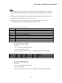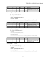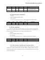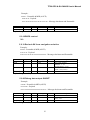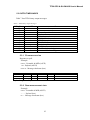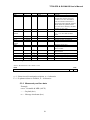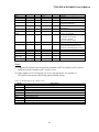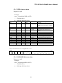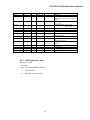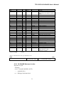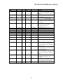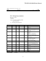
1
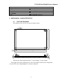
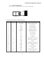
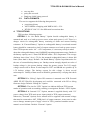
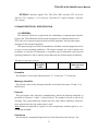
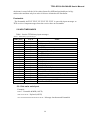
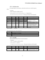
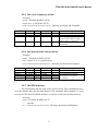
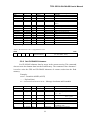
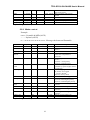
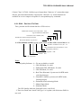
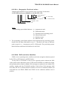
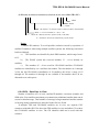
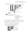
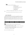
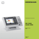
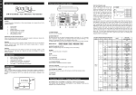
TF50 GPS & GLONASS
Embedded Solutions
Laipac Technology, Inc.
105 West Beaver Creek Rd. Unit 207 Richmond Hill Ontario L4B 1C6 Canada
Tel: (905) 762-1228 Fax: (905) 770-6143 / 763-1737
http://www.laipac.com
TF50 GPS & GLONASS User's Manual
Contents
1. Gener al Descr iption . . . . . . . . . . . . . . . . . . . . . . . . . . . . . . . . . . . . . . . . . . . 4
1.1 Introduction
… … .. . . . . . . . . . . . . . . . . . . . . . . . . . . . . . . . . . . . . . . . . 4
1.2 General view .. . . . . . . . . . . . . . . . . . . . . . . . . . . . . . . . . . . . . . . . . . . . .4
1.3 Antenna requirements … … … … … … … … . . . . . . . . . . . . . . . . . . . . . . . .5
1.4 Specification … … … … … .. . . . . . . . . . . . . . . . . . . . . . . . . . . . . . . . . . . ..6
2. Mechanical Char ater istics . . . . . . . . . . . . . . . . . . . . . . . . . . . . . . . . . . . . . .9
2.1 Outline drawing … … . . . . . . . . . . . . . . . . . . . . . . . . . . . . . . . . . . . . . . . .9
2.2 Output connector … … .. . . . . . . . . . . . . . . . . . . . . . . . . . . . . . . . . . . . . . .10
3. Inter faces . . . . . . . . . . . . . . . . . . . . . . . . . . . . . . . . . . . . . . . . . . . . . . . . . . . .11
3.1 Electrical specification … … … … … … … … … ... . . . . . . . . . . . . . . . . . . .11
3.2 Data formats … … … … … … … . . . . . . . . . . . . . . . . . . . . . . . . . . . . . . . . .12
4. TF50 Options . . . . . . . . . . . . . . . . . . . . . . . . . . . . . . . . . . . . . . . . . . . . . . . . 12
5. Binar y Protocol Specification . . . . . . . . . . . . . . . . . . . . . . . . . . . . . . . . . . . 13
5.1 General … … … . . . . . . . . . . . . . . . . . . . . . . . . . . . . . . . . . . . . . . . . . . . . .13
5.2 Input messages… … … … . . . . . . . . . . . . . . . . . . . . . . . . . . . . . . . . . . . . . 14
5.2.1 Set main serial port … … … . . . . . . . . . . . . . . . . . . . . . . . . . . . . . . . .14
5.2.2 Poll firmware version … … … . . . . . . . . . . . . . . . . . . . . . . . . . . . . . . .15
5.2.3 Initialize data … … … .. . . . . . . . . . . . . . . . . . . . . . . . . . . . . . . . . . . .. 16
5.2.4 Set GMT … … … … … … … … … … … … … . . . . . . . . . . . . . . . . . . . ..16
5.2.5 Set clock frequency offset … … … … … … … … … … .. . . . . . . . . . . .. 17
5.2.6 Set approximate user position… … … … … … ... . . . . . . . . . . . . . . . . .17
5.2.7 Set GPS almanac … … … … … … … ... . . . . . . . . . . . . . . . .. . . . . . . . .17
5.2.8 Set GLONASS almanac … … … … … … … … … … … … … . . . . . . . . 18
5.2.9 Mode control … … … … … … … .. . . . . . . . . . . . . . . . . . . . . . . . . .19
5.2.10 Poll clock status … … … … … … … … … … … … … . . . . . . . . . . . . . ..20
5.2.11 Poll GPS almanac … … … … … … … … … … … … … … . . . . . . . . . . .20
5.2.12 Poll GLONASS almanac … … … … … … … … … … … … . . . . . . . . ..21
5.2.13 Poll GPS ephemeris … … … … … … … … … … … … … … .. . . . . . . . .21
5.2.14 Poll GLONASS ephemeris … … … … … … … … … … … … … … .. . . 21
5.2.15 Poll navigation parameters … … … … … … … … … … … … ... . . . . . .22
2
TF50 GPS & GLONASS User's Manual
5.2.16 Store almanacs … … … … . . . . . . . . . . . . . . . . . . . . . . . . . . . . . . . . 22
5.2.17 Store last user position and frequency offset … … … … … … … … ...22
5.2.18 DGPS control … … … … … … … … … … … … … ... . . . . . . . . . . . . .. 23
5.2.19 Exclude SV from navigation solution … … … … … … … … … … … .23.
5.2.20 Debug data output ON/OFF … … … … … … … … … … … ... . . . . .… 23
5.2.21 Switch to NMEA protocol … … … … … … … .. . . . . . . . . . . . . . . . ..24
5.3 Output messages … … … … … … . . . . . . . . . . . . . . . . . . . . . . . . . . . . . . 25
5.3.1 Firmware version … … … … .. . . . . . . . . . . . . . . . . . . . . . . . . . . . . . . 25
5.3.2 Raw measurement data … … … … … … … ... . . . . . . . . . . . . . . . . . . ..25
5.3.3 Measured position data … … … … … … . . . . . . . . . . . . . . . . . . . . . . ..26
5.3.4 Clock status … … … … … … … … … … … … . . . . . . . . . . . . . . . . . . . .27
5.3.5 GPS almanac data … … … … … … … .… … … … … … .. . . . . . . . . . . ..29
5.3.6 GLONASS almanac data … … … … … … … … ... . . . . . . . . . . . . . . . .29
5.3.7 GPS ephemeris data … … … … … … … .. .. . . . . . . . . . . . . .. . . . . . . . 30
5.3.8 GLONASS ephemeris data … … … … … … … … … .… … … . . . . . . . 31
5.3.9 Navigation parameters … … … … … .. . . . . . . . . . . . . . . . . . . . . . . . ..33
5.3.10 Command acknowledgement … … … … … … … … … . . . . . . . . . . . .34
5.3.11 Command Nacknowledgement … … … … … … … .… … . . . . . . . . . .34
6. NMEA Protocol Specification … … … . . . . . . . . . . . . . . . . . . . . . . . . . . . . .35
6.1 General … ..… … … … … … … … … . . . . . . . . . . . . . . . . . . . . . . . . . . . . . 35
6.2 Output messages ..… … … … … … … .. . . . . . . . . . . . . . . . . . . . . . . . . . ..35
6.2.1 GGA – Position data … … … … … ... . . . . . . . . . . . . . . . . . . . . . . . . .36
6.2.2 GLL – Geographic position – Lat/Lon … … … … … . . . . . . . . . . . ...37
6.2.3 GSA – DOP and active satellites … … … … … . . . . . . . . . . . . . . . . . .37
6.2.4 GSV – Satellites in view … … … … … … … … ... . . . . . . . . . . . . . . . . 38
6.2.5 RMC – Recommended minimum specific GNSS data … … … . . . . .39
6.2.6 VTG – Track made good and ground speed … … … … … .. . . . . . . . . 40
6.3 Input messages ..… … … … … … … .. . . . . . . . . . . . . . . . . . . . . . . . . . . .. 41
6.3.1 XYZ initialization … … … … … … … … ... . . . . . . . . . . . . . . . . . . . . . 42
6.3.2 LLA initialization … … … … … … … … … … … … … . . . . . . . . . . . . . 42
6.3.3 DGPS control … … … … … … … … … .… … … . . . . . . . . . . . . . . . . . ..43
6.3.4 Rate control … … … … … … … … … … … … … ... . . . . . . . . . . . . . . . . 43
6.3.5 Store position … … … … … … … … … … … … … … … … … … … . . . . .44
6.3.6 Store almanacs … … … … … … … … … … … … .… … … … .. . . . . . . . .44
6.3.7 Switch to binary protocol … … … … … … … … … … … … .. . . . . . . . .44
3
TF50 GPS & GLONASS User's Manual
1.
GENERAL DESCRIPTION
1.1. INTRODUCTION
TF50 is a OEM engine board designed for calculation of coordinates,
velocity vector, heading and time using signals of the satellite navigation systems
GLONASS (Russia) and GPS (USA). Receiver uses two asynchronous serial ports
RS-232 to communicate with external equipment. The receiver can operate in
autonomous and differential modes. TF50 generates one second time mark (1PPS
signal) which is synchronous to the selected time scale.
Signal structures of GLONASS and GPS navigation systems are similar that
allows to design combined receivers with lower extra components in comparison with
one-system receivers (for example, GPS only). It is known, that GPS consists of 24
satellites, placed on six orbits in six planes. GPS uses CDMA (Code Division Multiple
Access) for different space vehicles (SV). SV numbers comply with Gold codes
numbers. The nominal carrier frequency value in L1 frequency range for all GPS SV is
equal to 1575,42 MHz.
GLONASS provides 24 SV, placed on three orbits in three planes. GLONASS
uses FDMA (Frequency Division Multiple Access) with uniform code sequence for all
SV. The nominal values of carrier frequency at L1 frequency range are defined by
following expression:
Fn = 1602,000 MHz + k × ∆F,
where k – frequency position number (frequency channel), k
= -7… +12;
∆F = 0,5625 MHz – frequency step between neighbor
frequency positions.
At present time SV transmitting signals with numbers k = 0… 12 only are available. 0
(zero) frequency channel signal is used for technical purposes only but not for
navigation (refer to GLONASS ICD).
1.2.
GENERAL VIEW
TF50 General view is shown in figure below.
4
TF50 GPS & GLONASS User's Manual
JP2 EZ-ICE Debug
RF
RF Connector
Connecto
r
JP2 EZ-ICE Debug
Connector
Connector(optional)
TF50 rev.X
GPS/GLON RCVR
JP1 Output
Connector
LED "MODE"
(optional)
Super Cap (optional)
Rechargeable
Li battery (optional)
The PCB of the receiver has dimensions 71 mm × 51 mm. MCX female connector is
used for connection to an active antenna. Antenna power supply is provided via central
wire of coaxial cable. Using antennas from third party vendors must be taken carefully
because of TF50 antenna’s power supplying circuit has 100 mA current limitations.
Moreover for current design TF50 must use only active antenna so the connection
to passive antennas is prohibited.
20-pin two rows 2.0x2.0 mm pin strip header (for example, 151220-2420TH from 3M)
is used as a output connector.
1.3. ANTENNA REQUIREMENTS
Third party vendor active GPS/GLONASS antenna for TF50 should meet following
requirements:
1. 3dB Bandwidth
1570… 1610 MHz
2. Impedance
50Ω
3. Polarization
RHCP
4. Gain*
20… 30 dB
5. Noise Figure
2.0 dB max
5
TF50 GPS & GLONASS User's Manual
6. VSWR
1.5 dB
7. Current
100 mA Max
8. Supply Voltage**
5V
Notes:
* Actually TF50 requires 15~25 dB of additional gain for its proper operation.
Additional gain less than 15 dB may cause the total receiver noise figure and sensitivity
degradation. Additional gain more than 25 dB may cause easy non-linear suppression of
GLONASS or GPS signals by out-of-band interfering signals.
Additional gain is defined as antenna LNA minus cable losses. Cable losses depend on
cable type and its length. Generally, the greater outer diameter of cable, the less loss it
will be.
** For TF50 “External ”Option.
If the receiver is expected to use as a GPS only receiver, it is possible to use GPS only
antennas.
1.4. SPECIFICATION
1. Gener al
1.1 Frequency
L1
L2
1.2 Supported signals
GPS (C/A)
GLONASS (C/A)
WAAS
EGNOS
GALILEO
CHINA SATs
1.3 Channels
16
1.4 Tracking capability
Carrier-aided tracking
2. Per for mance
2.1 Autonomous mode, PDOP <4
2.1.1 Plane
CEP
GPS
GLONASS
GPS+ GLONASS
2Drms
+
+
+
+
+
9m
8m
7m
6
TF50 GPS & GLONASS User's Manual
GPS
GLONASS
GPS+ GLONASS
2.1.2 Height
CEP
GPS
GLONASS
GPS+ GLONASS
rms
GPS
GLONASS
GPS+ GLONASS
2.1.3 Velocity
rms
GPS+ GLONASS
2.1.4 Time
rms
GPS+ GLONASS
2.2 Differential mode
2.2.1 Coordinates
CEP
2.2.2 Velocity
2Drms
2.3 Acquisition time (TTFF) (mean)
Hot start
Warm start
Cold start
Reacquisition
2.4 Dynamics
Speed (max.)
Altitude (max.)
Acceleration
Jerk
2.5 Update rate
Hz (max.)
3. Inter faces
3.1 Communication
Baud rate
EIA RS-232
3.2 1 PPS
Duration (u sec)
Level
Time scale
GPS time
GLONASS time
UTC (USNO)
UTC (SU)
Pulse
24 m
20 m
14 m
14 m
13 m
8m
40 m
38 m
25 m
0.05 m/s
0.1 µs
3m
0.1 m/s
5 s (stored almanac,ephemeris,time,position)
30 s(stored almanac,time,position)
120 s(no almanac,ephemeris,time,position)
1s
950 m/s
18 km
6g
1 g/s
5 Hz
900 ~ 115200
+ (see “OPTION 5” in Section 4)
10
TTL
+
+
7
TF50 GPS & GLONASS User's Manual
Positive/Negative
Programmable
3.3 Output data
Datum
WGS84 and PZ90
Time difference
Velocity
Heading
Channel status
Ephemeris data
Almanac data
Raw measurement data
3.4 Data formats
Output
NMEA 0183
Version
Baud rate (default)
Binary
Version
Baud rate (default)
Differential
RTCM SC-104
Version
Baud rate (default)
Types
3.5 Prime Power
Input voltage
Supplied current
Backup voltage
Backup current
LED configuration
On board rechargeable Li battery
4. Physical
4.1 Dimensions
W x L x H (mm)
Weight (g)
4.2 Antenna connector
Type
4.3 Output connector
20-Pin I/O, 2.0 mm
Debug 14-Pin I/O
5. Antenna
5.1 Antenna type
Active antenna
5.2 Requirement
5.3 Input Power
External voltage
6. Environmental
P
-
+
+
+
+
+
+
+
+
2.30
4800
4.0x
9600
2.2
9600
TBD
3.3 V +- 5%
200 mA typ.
1.5 ~ 3.3 V
50µA @ 3.0V
see “OPTION 3” in Section 4
see “OPTION 1 “ in Section 4
71 x 51 x 12
< 50 g
MCX(optional:SMA),straight or right angle
Straight header (optional: other directions)
- (see “OPTION 2” in Section 4)
+ (passive antenna not recommended)
see Section 1.3
5.0 V (see “OPTION 4” in Section 4)
8
TF50 GPS & GLONASS User's Manual
6.1 Operating temp.
Degree
6.2 Storage temp.
Degree
6.3 Vibration
Hz
-40 to +85 o C
-40 to +85 o C
20 to 1000 Hz, 2 to 12 g
2. MECHANICAL CHARACTERISTICS
2.1. OUTLINE DRAWING
The outlines of the receiver are given in figure below.
3mm
51 mm
3.0mm
45 mm
4 holes
65 mm
4mm
1.5mm
6mm
5.0mm
71 mm
TF50 has the following dimensions: 71 mm (length), 51 mm (width).
The height of top side components is 5 mm. The height of bottom side components
is 4 mm. There are 4 mounting holes 3.0 mm in diameter.
9
TF50 GPS & GLONASS User's Manual
2.2. OUTPUT CONNECTOR
General top view of output connector (JP1) is shown in figure below.
20
RF
19
DIGITAL
2
1
TF50 PCB
The table below contains list of input/output signals.
Pin
Type
Name
1
I
2
Descr iption
ANT_PWR
External Antenna Power
NC
Not Connected
3
I
BAT
Back Up Battery
4
I
VDD
3.3V Power Input
5
I
M_RES
Manual Reset Input
6
I
PRG_FL
Programming Control
7
I
NC
Not Connected
8
NC
Not Connected
9
NC
Not Connected
10
GND
Ground
11
O
TX1
Transmit Data, Serial Port 1
12
I
RX1
Receive Data, Serial Port 1
GND
Ground
13
14
O
TX2
Transmit Data, Serial Port 2
15
I
RX2
Receiver Data, Serial Port 2
GND
Ground
ETM
External Time Mark
GND
Ground
1PPS
1PPS Time Mark Output
NC
Not Connected
16
17
I
18
19
20
O
10
TF50 GPS & GLONASS User's Manual
ANT_PWR
external antenna power supply voltage
BAT
external back-up battery voltage, 1.5~3.3V
VDD
main power supply voltage, +3.3V.
M_RES
manual reset signal, active low with internal pull-up in MAX793. M_RES has pull-up
current 250µA max. Pulse width for this input should be at least 100ns.
PRG_FL
programming flag, active low, connected with 20kOhm pull-up resistor. For TF50
it’s possible to upload firmware to the FLASH via serial port. It’s considered that for
OK uploading no power, host personal computer or communication failures should
occur during this procedure. If some failures took place and uploading procedure was
completed with errors, it’s necessary to make PRG_FL low and repeat the uploading
procedure.
TX1, TX2
transmit data via serial port#1 and #2.
RX1, RX2
receive data via serial port#1 and #2.
ETM
external time mark. TF50 can measure the time of external time mark
1PPS
output one second time mark, pulse width is about 10 µs. Its polarity (positive or
negative) can be programmed by control command via serial port. Default is positive.
3. INTERFACES
3.1. ELECTRICAL SPECIFICATION
The receiver has two serial asynchronous ports (Port#1 and Port#2) for communication
with external equipment. Each port has two options: the first meets the EIA RS-232
standard electrical specification and the second has TTL logic levels.
The receiver supports following software selectable serial port parameters –
900… 115200 bit/s baud rate; 5-, 6-, 7- or 8-bit data length; 1 or 2 stop bits; even, odd or
no parity.
The default serial port configurations parameters are as follows:
•
data length:8 bits
11
TF50 GPS & GLONASS User's Manual
• two stop bits
• parity bit: not used.
• Baud rate: 9600, binary protocol
3.2. DATA FORMATS
The receiver supports the following data protocols:
• proprietary binary
• ASCII NMEA complying with NMEA 0183 v.2.30
• RTCM SC-104 V.2.2 for differential corrections data
4. TF50 OPTIONS
TF50 can have following options:
OPTION 1. In “On Board Battery” Option 8mAh rechargeable battery is
mounted and used as a back-up power source when main power is off. There is a
charger circuit for rechargeable battery consisting of diode and current limiting
resistance. In “External Battery” Option no rechargeable battery is used and external
battery should be connected to pin#3 of output connector as a back-up power source.
Since TF50 operates under - 40 ~ +85ºC temperature, it’s necessary to keep in mind
about the rechargeable battery more NARROW operating temperature range. Besides it
the battery capacity can 1.5 times DECREASE under –20ºC temperature. The average
discharge time (from 3.0 to 1.5V) for the mounted rechargeable battery is about 400
hours (more than 16 days). Default: “On Board Battery” Option. Important notice for
the case of external backup battery use. Backup current strongly depends on value of
backup voltage i.e. the greater backup voltage the greater current. For 3.0V supply
voltage current will be about 50 microamperes. RTC and SRAM are operable up to
1.5V backup voltage. The backup current for this voltage is about several
microamperes. Validity of data stored in SRAM is guaranteed by verifying data check
sum.
OPTION 2. In “Debug” Option JP2 connector is mounted onto PCB. External
ADSP EZ-ICE Elite-Kit development tool could be connected with JP2 to debug
firmware design. Default: “Debug-No” Option.
OPTION 3. The aim for “LED” Option is to indicate different TF50 current
modes of operation such as searching, tracking, or navigation. Default: “LED” Option.
OPTION 4. In “Internal 3.3V” Option, antenna is supplied directly with 3.3V
power voltage from TF50 main power input (pin#4 in TF50 output connector).
Otherwise (“External” Option) active antenna will be supplied with external voltage
that must be connected to ANT_PWR pin #1 of output connector. At any case in order
not to damage antenna power supply circuit in TF50, permitted antenna current
mustn’t exceed 100mA. Default: “External “ Option
12
TF50 GPS & GLONASS User's Manual
OPTION 5. Interface signals TX1, TX2, RX1, RX2 can have TTL levels for
“RS-232 TTL” Option or +-6V levels for “EIA RS-232” Option. Default: “EIA RS232” Option.
5. BINARY PROTOCOL SPECIFICATION
5.1 GENERAL
This Protocol defines the requirements for establishing a communication interface
between the TF50 OEM board and external equipment via communication Port #1.
TF50 can receive input messages from the external equipment, and can send output
messages to the external equipment.
The input messages are control commands by which the external equipment can set
or query various operating parameters. The output messages are used to indicate the
acceptance or rejection of commands, to respond to query commands with requested
operating parameters, and to output position data and raw measurements periodically.
The general message structure
Preamble
Message
Identifier
(MID)
Payload
Checksum
Postamble (for
input messages
only)
Preamble
The Preamble is sent in the following order: "F" is first byte, "T" is last byte.
Message Identifier
The possible values of the Message identifier are defined in Sections 5.2 and 5.3 of
this Protocol.
Payload
The byte-length of the Payload is unambiguously defined by Message Identifier as
specified in Sections 5.2 and 5.3 of this Protocol. The number of bytes is odd for all
messages. The payload data may content any 8-bit value. Where multi-byte values are
in the payload data, the big-endian order is used.
Note: Parameters indicated as "signed" are two's complement, with the sign bit (+ or -)
occupying the MSB.
Checksum
The checksum is transmitted high order byte first followed by the low byte. The
13
TF50 GPS & GLONASS User's Manual
checksum is sum of all the 16-bit values formed by MID and payload bytes in bigendian order and then only low-order 16 bits are retained as the checksum.
Postamble
The Postamble 0xFF FF FF FF FF FF FF FF FF FF is sent with input messages to
TF50 receiver. Output messages from the receiver have no Postamble.
5.2 INPUT MESSAGES
Table 1 lists the TF50 binary input messages.
Table 1 TF50 binary input messages
MID (Hex)
0x31
0x56
0x32
0x54
0x46
0x58
0x33
0x34
0x35
0x43
0x41
0x4C
0x49
0x45
0x50
0x53
0x55
0x44
0x5A
0x42
0x4D
ASCII
1
V
2
T
F
X
3
4
5
C
A
L
I
E
P
S
U
D
Z
B
M
Name
Set main serial port
Poll firmware version
Initialize data
Set GMT
Set clock frequency offset
Set approximate user position
Set GPS Almanac
Set GLONASS Almanac
Mode control
Poll clock status
Poll GPS Almanac
Poll GLONASS Almanac
Poll GPS Ephemeris
Poll GLONASS Ephemeris
Poll Navigation parameters
Store Almanacs
Store last user position and frequency offset
DGPS control
Exclude SV
Debug data output ON/OFF
Switch to NMEA Protocol
5.2.1 Set main serial port
Example:
FAST1 - Preamble & MID (ASCII)
0x00 01 97 0F 0F - Payload (ASCII)
0x41 A6 FF FF FF FF FF FF FF FF FF FF -
Message checksum and Postamble
14
TF50 GPS & GLONASS User's Manual
Name
MID
Reserved
Baud rate
Data format
Bytes
Scale
1
1
2
2
Payload length:
Units
Descr iption
ASCII 1
coded
bitmap
See Table 2
See Table 3
5 bytes
Table 2 Baud rate codes
900
1200
Baud
r ate
0x02 17 0x01 97
Code
Baud
r ate
Code
Example
0x31
0x00
0x01 97
0x0F 0F
1800
2400
3600
4800
7200
9600
0x02 16
0x01 96
0x02 15
0x01 95
0x02 14
0x01 94
14400
19200
28800
38400
57600
76800
115200
153600
0x02 13
0x01 93
0x02 12
0x01 92
0x02 11
0x01 91
0x02 10
0x01 90
Table 3 Bit allocation in the "Data format" word
MSB
Tr ansmitter
Reserved
P
S
L
1
2
3
4
5
6
7
8
LSB
Reserved
9
10
11
Receiver
P
12
13
S
14
L is length field: number of data bits = L + 5
S is stop bit field: number of stop bits = S + 1
P is parity field:
P = 000 or 100 or 010 or 110:
none
P = 001:
even
P = 011:
odd
P = 101:
always zero
P = 111:
always one
5.2.2 Poll Firmware Version
Example:
FASTV - Preamble & MID (ASCII)
0x00 00 00- Payload (ASCII)
0x56 00 FF FF FF FF FF FF FF FF FF FF
Name
MID
Reserved
Bytes
Scale
1
3
Payload length:
- Message checksum and Postamble
Example
0x56
0x00
3 bytes
15
Units
Descr iption
ASCII V
L
15
16
TF50 GPS & GLONASS User's Manual
5.2.3 Initialize data
Sets approximate user position, current time and receiver clock frequency
offset.
Example:
FAST2 - Preamble & MID (ASCII)
- Payload (hex)
0x53 20 FF FF FF FF FF FF FF FF FF FF - Message checksum and Postamble
0x00 10 FB 0D 09 1F 4D 3A 5D 82 62 00 00 27 10
Name
MID
Reset Config.
ECEF X
ECEF Y
ECEF Z
GMT
Bytes
1
1
2, signed
2, signed
2, signed
4
Freq. Offset
Freq. Range
Bitmap
cm
cm
cm
seconds
2, signed
Example
0x32
0x00
0x10 FB
0x0D 09
0x1F 4D
0x3A 5D 82
62
0x00 00
2
0x27 10
Hertz
Payload length:
Scale
*216
*216
*216
Units
Hertz
Descr iption
ASCII 2
See Table 4
Approximate user position:
X=2849 km, Y= 2187 km,
Z= 5252 km
Number of seconds elapsed since
the beginning of January 1, 1970
Estimate frequency offset of the
receiver clock relative to GPS
carrier, range= ± 32767 Hz
Uncertainty of the clock frequency
(10000 Hz)
15 bytes
Table 4 Bit allocation in the "Reset Config" byte
Config
Descr iption
0x00
Enable warm/hot start
0x01
Clear ephemeris - set cold start
0x02
Clear ephemeris&almanac - set initial acquisition start
0x03… 0xff
TBD
5.2.4 Set GMT
Sets Greenwich Mean Time for current moment .
Example:
FASTT - Preamble & MID (ASCII)
0x00 3A 5D 82 62 - Payload
0x10 BF FF FF FF FF FF FF FF FF FF FF - Message checksum and Postamble
Name
MID
Reserved
GMT
Bytes
Scale
1
1
4
Payload length:
Example
0x54
0x00
0x3A 5D 82
62
5 bytes
16
Units
Descr iption
ASCII T
seconds
Number of seconds elapsed since
the beginning of January 1, 1970
TF50 GPS & GLONASS User's Manual
5.2.5 Set clock frequency offset
Example:
FASTF - Preamble & MID (ASCII)
0x00 00 00 27 10- Payload (ASCII)
0x6D 10 FF FF FF FF FF FF FF FF FF FF - Message checksum and Postamble
Name
MID
Reserved
Freq. offset
Bytes
1
1
2, signed
Freq. range
2
Payload length:
Scale
Example
0x46
0x00
0x00 00
Units
Hertz
0x27 10
Hertz
Descr iption
ASCII F
Estimate frequency offset of the
receiver clock relative to GPS
carrier, range= ± 32767 Hz
Uncertainty of the clock frequency
(10000 Hz)
5 bytes
5.2.6 Set approximate user position
Example:
FASTX - Preamble & MID (ASCII)
0x00 10 FB 0D 09 1F 4D - payload (hex)
0x95 51 FF FF FF FF FF FF FF FF FF FF - Message checksum and Postamble
Name
MID
Reserved
ECEF X
ECEF Y
ECEF Z
Bytes
1
1
2, signed
2, signed
2, signed
Payload length:
Scale
*216
*216
*216
Example
0x58
0x00
0x10 FB
0x0D 09
0x1F 4D
Units
Descr iption
ASCII X
cm
cm
cm
Approximate user position:
X=2849 km, Y= 2187 km,
Z= 5252 km
7 bytes
5.2.7 Set GPS Almanac
Set GPS almanac data for usage in the current session. This command does not
write the almanac data into the flash memory. The command "Store almanacs" is used
to write the GPS and GLONASS almanacs of current session into the flash memory.
Example:
FAST3 - Preamble & MID (ASCII)
---… -- Payload
0x---- FF FF FF FF FF FF FF FF FF FF - Message checksum and Postamble
17
TF50 GPS & GLONASS User's Manual
Name
MID
PRN
Wna
Wn
Tow
1
1
2
2
4
Bytes
config&health
E
Toa
i0
Omegadot
Roota
omega0
Omega
m0
af0
af1
2
2
2
2, signed
2, signed
4
4, signed
4, signed
4, signed
2, signed
2, signed
Payload length:
Scale
Example
0x33
Units
seconds
*2-21
seconds
semicycles
semicycles/sec
meters1/2
semicycles
semicycles
semicycles
seconds
sec/sec
*2-19
*2-38
*2-11
*2-23
*2-23
*2-23
*2-20
*2-38
Descr iption
ASCII 3
Satellite PRN number (1-32)
Almanac week number
Receive time week number
Second of GPS week (receive
time)
See Table 5
Eccentricity
Almanac reference time
Inclination angle
Rate of right ascension
Square root of semi-major axis
Longitude of ascending node
Argument of perigee
Mean anomaly at reference time
Clock correction
Clock correction
39 bytes
Table 5 Bit allocation in the "config&health" word
MSB
SV config (see
ICD GPS-200C)
1
2
3
4
5
6
7
8
LSB
9
Satellite data&signal health
(see ICD GPS - 200C)
10
11
12
13
14
15
16
5.2.8 Set GLONASS Almanac
Set GLONASS almanac data for usage in the current session. This command
does not write the almanac data into the flash memory. The command "Store almanacs"
is used to write the GPS and GLONASS almanacs of current session into the flash
memory.
Example:
FAST4 - Preamble & MID (ASCII)
---… -- Payload (hex)
0x---- FF FF FF FF FF FF FF FF FF FF - Message checksum and Postamble
Name
MID
SV ID
Litera
Bytes
1
1
1, signed
Scale
Example
0x34
Units
Health
1
Reserved
Na
Ln
Tln
8
2
4, signed
4
*2-20
*2-5
days
semicycles
seconds
Di
4, signed
*2-20
semicycles
18
Descr iption
ASCII 4
Satellite number (1-24)
Satellite frequency number
(-7… 12)
Satellite health: 0x30 = bad
0x31 = good
TBD
Reference day number
Longitude of first ascension node
Reference time of the first
ascending node
Correction to inclination
TF50 GPS & GLONASS User's Manual
DT
4, signed
*2-9
s/orbit_period
Dtdot
1, signed
*2-14
s/orbit_period2
Reserved
E
Omega
tn
5
2
2, signed
2, signed
*2-20
*2-15
*2-18
semicycles
seconds
Payload length:
Correction to the mean value of
Draconian period
Rate of change of Draconian
period
TBD
Eccentricity
Argument of perigee
Satellite time correction
41 bytes
5.2.9 Mode control
Example:
FAST5 - Preamble & MID (ASCII)
---… -- Payload (ASCII)
0x---- FF FF FF FF FF FF FF FF FF FF - Message checksum and Postamble
Name
MID
Pos Mode
Bytes
Scale
1
1
Example
0x35
Units
bitmap
Alt_For_Hold
Clock hold
timeout
2
1
meters
seconds
Hold priorities
1
GLONASS
Tshift
4, signed
Tshift alg
1
NSV
Tshift priority
1
1
Elevation
mask
SNR mask
PDOP mask
1
1
1
*2-3
HDOP mask
1
*2-3
Update_rate
Reserved
1
6
*0.2
Payload length:
23 bytes
cm
degrees
seconds
19
Descr iption
ASCII 5
Position fix mode control, see
Table 6
Time interval during which the
clock bias extrapolation is
allowable
Priority against altitude and
Tshift(1):
C(0x43) = clock priority
A(0x41)= altitude priority
GLONASS system time shift
(divided by speed of light) relative
to GPS time
Tshift fixing algorithm:
N (0x4D)= never fixed
~ (0x7E)= flexible(2)
F(0x46)= always fixed
Number of SV to compute Tshift
Priority against altitude(3):
T(0x54)= Tshift higher priority
A(0x41)= altitude higher priority
Elevation mask for Navigation
solution
SNR mask for Navigation solution
PDOP mask for Navigation
solution(1)
HDOP mask for Navigation
solution(1)
Output position update rate
TBD
TF50 GPS & GLONASS User's Manual
Notes:
(1) If the number of SV in solution is 4 or less, this parameter sets priority of clock rate
fixing against altitude fixing or GLONASS system time shift fixing, see also Note
(3).
(2) Compute GLONASS system time shift if number of SV in solution is nSV or more,
and hold it fixed if number of SV is nSV or less.
(3) If the number of SV in solution is 4 or less, this parameter sets priority of
GLONASS system time shift fixing against altitude fixing.
Table 6 Bit allocation in the "Pos Mode" word
Mode
Descr iption
0x00
Only 3D solution allowable
0x01
1 satellite solution allowable
0x02
2 satellite solution allowable
0x03
3 satellite solution (2D) allowable
0x04
4 satellite solution (3D) allowable
0x08
Reserved
0x10
Altitude hold mode allowable
0x20
Clock hold mode allowable
0x40
Recent computed altitude must be used for altitude hold mode, otherwise Alt_For_Hold
0x80
Reserved
5.2.10 Poll clock status
Example:
FASTC - Preamble & MID (ASCII)
0x00 00 00 - Payload (ASCII)
0x43 00 FF FF FF FF FF FF FF FF FF FF
Name
MID
Reserved
Bytes
Scale
1
3
Payload length:
Example
0x43
0x00
- Message checksum and Postamble
Units
Descr iption
ASCII C
3 bytes
5.2.11 Poll GPS Almanac
Example:
FASTA - Preamble & MID (ASCII)
0xFF 00 00 - Payload
0x41 FF FF FF FF FF FF FF FF FF FF FF
20
- Message checksum and Postamble
TF50 GPS & GLONASS User's Manual
Name
MID
PRN
1
1
Bytes
Reserved
2
Payload length:
Scale
Example
0x41
0xFF
Units
Descr iption
ASCII A
GPS satellite PRN number (1-32)
0xFF requests all available GPS
almanac records
3 bytes
5.2.12 Poll GLONASS Almanac
Example:
FASTL - Preamble & MID (ASCII)
0x20 00 00 - payload
0x4C 20 FF FF FF FF FF FF FF FF FF FF - Message checksum and Postamble
Name
MID
PRN
1
1
Bytes
Example
0x4C
0x20
Reserved
2
0x00 00
Payload length:
Scale
Units
Descr iption
ASCII L
GLONASS satellite number (1-24)
0xFF requests all available
GLONASS almanac records
3 bytes
5.2.13 Poll GPS Ephemeris
Example:
FASTI - Preamble & MID (ASCII)
0x20 00 00- Payload
0x49 20 FF FF FF FF FF FF FF FF FF FF
Name
MID
PRN
1
1
Bytes
Example
0x49
0x20
Reserved
2
0x00 00
Payload length:
Scale
- Message checksum and Postamble
Units
Descr iption
ASCII I
GPS satellite PRN number (1-32)
0xFF requests all available GPS
ephemeris records
3 bytes
5.2.14 Poll GLONASS Ephemeris
Example:
FASTE - Preamble & MID (ASCII)
0x18 00 00- Payload
0x45 18 FF FF FF FF FF FF FF FF FF FF - Message checksum and Postamble
21
TF50 GPS & GLONASS User's Manual
Name
MID
PRN
1
1
Bytes
Example
0x45
0x18
Reserved
2
0x00
Payload length:
Scale
Units
Descr iption
ASCII I
GLONASS satellite number (1-24)
0xFF requests all available
GLONASS ephemeris records
3 bytes
5.2.15 Poll Navigation parameters
Example:
FASTP - Preamble & MID (ASCII)
0x00 - Payload
0x50 00 FF FF FF FF FF FF FF FF FF FF - Message checksum and Postamble
Name
MID
Reserved
Bytes
Scale
1
3
Payload length:
Example
0x50
0x00
Units
Descr iption
ASCII P
3 bytes
5.2.16 Store Almanacs
Writes the GPS and GLONASS almanacs received in current session into the
flash memory. Output position and raw measurement data may be suspended for
several seconds during the process of writing into the flash memory.
Example:
FASTS - Preamble & MID (ASCII)
0x00 - Payload
0x53 00 FF FF FF FF FF FF FF FF FF FF - Message checksum and Postamble
Name
MID
Reserved
Bytes
Scale
1
3
Payload length:
Example
0x53
0x00
Units
Descr iption
ASCII S
3 bytes
5.2.17 Store last user position and frequency offset
Writes the latest user position and frequency offset of the receiver clock
estimated in current session into the flash memory. Output position and raw
measurement data may be suspended for several seconds during the process of writing
into the flash memory.
22
TF50 GPS & GLONASS User's Manual
Example:
FASTU - Preamble & MID (ASCII)
0x00 00 00 - Payload
0x55 00 FF FF FF FF FF FF FF FF FF FF
Name
MID
Reserved
Bytes
Scale
1
3
Payload length:
Example
0x55
0x00
- Message checksum and Postamble
Units
Descr iption
ASCII U
3 bytes
5.2.18 DGPS control
TBD
5.2 19 Exclude SV from navigation solution
Example:
FASTZ - Preamble & MID (ASCII)
0x18 01 00 - Payload
0x5B 18 FF FF FF FF FF FF FF FF FF FF - Message checksum and Postamble
Name
MID
SVID
1
1
Bytes
Example
0x5A
0x18
ON/OFF
1
0x01
Reserved
1
Payload length:
Scale
Units
Descr iption
ASCII Z
SV system number:
GPS SV: 1… 32
GLONASS SV: 33-56
0x01 = OFF (exclude)
0x00 = ON (restore)
0x00
3 bytes
5.2.20 Debug data output ON/OFF
Example:
FASTB - Preamble & MID (ASCII)
0x30 00 00 - Payload
0x42 30 FF FF FF FF FF FF FF FF FF FF - Message checksum and Postamble
Name
MID
ON/OFF
1
1
Bytes
Example
0x42
0x30
Reserved
2
0x00 00
Payload length:
Scale
3 bytes
23
Units
Descr iption
ASCII B
0x30 - OFF
0x31 - ON
TF50 GPS & GLONASS User's Manual
5.2.21 Switch to NMEA Protocol
When a valid message is received, the parameters are stored in the non-volatile
memory, and then the receiver restarts using the saved parameters.
Example:
FASTM - Preamble & MID (ASCII)
0x------- - Payload
0x-- -- FF FF FF FF FF FF FF FF FF FF - Message checksum and Postamble
Name
MID
Reserved
GGA Talker ID
Bytes
1
1
1
GGA rate
GGA Checksum
1
1
GLL Talker ID
1
GLL rate
GLL Checksum
1
1
GSA Talker ID
1
GSA rate
GSA Checksum
1
1
GSV Talker ID
1
GSV rate
GSV Checksum
1
1
RMC Talker ID
1
RMC rate
RMC Checksum
1
1
VTG Talker ID
1
VTG rate
VTG Checksum
1
1
Payload length:
Scale
Example
0x4D
0x00
Units
*0.2
seconds
*0.2
seconds
*0.2
seconds
*0.2
seconds
*0.2
seconds
*0.2
seconds
19 bytes
24
Descr iption
ASCII M
NMEA Talker Identifier:
P=GP, L=GL, N=GN, 0=OFF
Output rate of GGA message
0x00 - disable checksum
0x01 - enable checksum
NMEA Talker Identifier:
P=GP, L=GL, N=GN, 0=OFF
Output rate of GLL message
0x00 - disable checksum
0x01 - enable checksum
NMEA Talker Identifier:
P=GP, L=GL, N=GN, 0=OFF
Output rate of GSA message
0x00 - disable checksum
0x01 - enable checksum
NMEA Talker Identifier:
P=GP, L=GL, N=GN, 0=OFF
Output rate of GSV message
0x00 - disable checksum
0x01 - enable checksum
NMEA Talker Identifier:
P=GP, L=GL, N=GN, 0=OFF
Output rate of RMC message
0x00 - disable checksum
0x01 - enable checksum
NMEA Talker Identifier:
P=GP, L=GL, N=GN, 0=OFF
Output rate of VTG message
0x00 - disable checksum
0x01 - enable checksum
TF50 GPS & GLONASS User's Manual
5.3 OUTPUT MESSAGES
Table 7 lists TF50 binary output messages.
Table 7 TF50 binary output messages
MID (Hex)
0x76
0x72
0x78
0x63
0x61
0x6C
0x69
0x65
0x70
0x62
0x2B
0x3F
ASCII
v
r
x
c
a
l
i
e
p
b
+
?
Name
Firmware version
Raw measurement data
Measured position data
Clock status
GPS Almanac data
GLONASS Almanac data
GPS Ephemeris data
GLONASS Ephemeris data
Navigation parameters
Debug data
Command acknowledgement
Command NAcknowledgement
5.3.1 Firmware version
Response to poll.
Example:
FASTv - Preamble & MID (ASCII)
1.02 - Payload (ASCII)
0xD7 60 - Message checksum (hex)
Name
MID
Reserved
F/W version
Bytes
Scale
1
1
4
Payload length:
Example
0x76
0x00
1.02
5 bytes
5.3.2 Raw measurement data
Example:
FASTr - Preamble & MID (ASCII)
---… -- Payload (hex)
0x---- Message checksum (hex)
25
Units
Descr iption
ASCII v
0x31 2E 30 32
TF50 GPS & GLONASS User's Manual
Name
MID
PRN
1
1
Bytes
Example
0x72
0x21
Warning
Carrier
number
1
1
0x0F
Sat X
Sat Y
Sat Z
Channel
number
SNR
SigR
4, signed
4, signed
4, signed
1
1
1
*0.1
meters
SigPhi
1
*2-10
cycles
Phase
Pseudorange
Doppler
Status
6, signed
4
4, signed
2
*2-12
*10-10
*10-4
cycles
s
Hz
bitmap
Payload length:
Scale
Units
cm
cm
cm
Descr iption
ASCII r
Satellite PRN number (1… 56). For
GLONASS satellites this field
content is 32 + SV slot number.
The slot number information is
derived from GLONASS Almanac.
When TF50 has ephemeris data
for a SV but no almanac, the PRN
number is set to zero.
TBD
GLONASS Carrier Number
(-7… +12). For GPS satellites:
0xFF
Satellite ECEF coordinate X
Satellite ECEF coordinate Y
Satellite ECEF coordinate Z
unsigned char
Signal-to-noise ratio
unsigned char
DLL residual
unsigned char
PLL residual
Full pseudo-doppler phase
Pseudo-doppler frequency
See Table 8
35 bytes
Table 8 Bit allocation in the "Status" word
MSB
Reserved
1
2
3
4
5
6
7
8
9
10
11
u = 1 if data is used in navigation solution, u = 0 otherwise
E = 1 if ephemeris data is available, E = 0 otherwise
5.3.3 Measured position data
Example:
FASTx - Preamble & MID (ASCII)
---… -- Payload (hex)
0x---- Message checksum (hex)
26
12
13
14
E
15
LSB
u
16
TF50 GPS & GLONASS User's Manual
Name
MID
Reserved
RcvTime
1
1
4
Bytes
X-position
Y-position
Z-position
R-offset
4, signed
4, signed
4, signed
4, signed
X-dot
Y-dot
Z-dot
R-dot
DOP
2, signed
2, signed
2, signed
2, signed
1
GPS SVs in fix
GLONASS
SVs in fix
Mode
1
1
Scale
Example
0x78
0x00
cm
cm
cm
cm
*32
*32
*32
*16
*8
Descr iption
ASCII x
ms
m/s
m/s
m/s
m/s
1
Payload length:
Units
Bitmap
Signal receive time in millisecond
of week of GPS time
Antenna ECEF coordinate X
Antenna ECEF coordinate Y
Antenna ECEF coordinate Z
Receiver clock offset in
centimeters
Antenna X velocity
Antenna Y velocity
Antenna Z velocity
Receiver clock shift
PDOP if position is obtained in 3D
solution, and HDOP otherwise
See Table 9
33 bytes
Table 9 Bit allocation in the "Mode" word
Mode
Descr iption
0x00
No navigation solution
0x01
1 satellite solution
0x02
2 satellite solution
0x03
3 satellite solution (2D)
0x04
≥4 satellite solution
0x08
Differential solution
0x10
Altitude hold mode
0x20
Clock hold mode
0x40
Recent computed altitude was used for altitude hold mode, otherwise Alt_For_Hold
0x80
Reserved
5.3.4 Clock status
Response to poll.
Example:
FASTc - Preamble & MID (ASCII)
---… -- Payload (hex)
0x---- Message checksum (hex)
27
TF50 GPS & GLONASS User's Manual
Name
MID
Reserved
wn
RcvTime
1
1
2
4
Bytes
R-offset
4, signed
R-dot
GLONASS
Tshift
Tshift alg
2, signed
4, signed
nSV
Tshift priority
1
1
Reserved
TDOP
GPS SVs in fix
GLONASS
SVs in fix
Mode
1
1
1
1
Scale
Example
0x63
0x00
Units
ms
cm
*16
m/s
cm
1
GPS week number
Signal receive time in millisecond
of week of GPS time
Receiver clock offset in
centimeters
Receiver clock shift
GLONASS system time shift
relative to GPS time
Tshift fixing algorithm:
N (0x4D)= never fixed
~ (0x7E)= flexible(1)
F(0x46)= always fixed
Number of SV to compute Tshift
Priority against altitude(2):
T(0x54)= Tshift higher priority
A(0x41)= altitude higher priority
*8
1
Payload length:
Descr iption
ASCII c
Bitmap
See Table 10
25 bytes
Notes:
(1) Compute GLONASS system time shift if number of SV in solution is nSV or more,
and hold it fixed if number of SV is nSV or less.
(2) If the number of SV in solution is 4 or less, this parameter sets priority of
GLONASS system time shift fixing against altitude fixing.
Table 10 Bit allocation in the "Mode" word
Mode
Descr iption
0x00
No navigation solution
0x01
1 satellite solution
0x02
2 satellite solution
0x03
3 satellite solution (2D)
0x04
≥4 satellite solution
0x08
Differential solution
0x10
Altitude hold mode
0x20
Clock hold mode
0x40
Recent computed was used for altitude hold mode, otherwise Alt_For_Hold
0x80
Reserved
28
TF50 GPS & GLONASS User's Manual
5.3.5 GPS Almanac data
Response to poll.
Example:
FASTa - Preamble & MID (ASCII)
---… -- Payload (hex)
0x---- Message checksum (hex)
Name
MID
PRN
1
1
Bytes
Wna
Wn
Tow
2
2
4
config&health
E
Toa
i0
Omegadot
Roota
omega0
Omega
m0
af0
af1
2
2
2
2, signed
2, signed
4
4, signed
4, signed
4, signed
2, signed
2, signed
Payload length:
Scale
Example
0x61
Units
seconds
*2-21
*2-19
*2-38
*2-11
*2-23
*2-23
*2-23
*2-20
*2-38
seconds
semicycles
semicycles/sec
meters1/2
semicycles
semicycles
semicycles
seconds
sec/sec
Descr iption
ASCII a
Satellite PRN number (1-32)
0x00 means "No data for requested
PRN"
Almanac week number
Receive time week number
Second of GPS week (receive
time)
See Table 11
Eccentricity
Almanac reference time
Inclination angle
Rate of right ascension
Square root of semi-major axis
Longitude of ascending node
Argument of perigee
Mean anomaly at reference time
Clock correction
Clock correction
39 bytes
Table 11 Bit allocation in the "config&health" word
MSB
SV config (see
ICD GPS-200C)
1
2
3
4
5
6
7
8
9
5.3.6 GLONASS Almanac data
Response to poll.
Example:
FASTl - Preamble & MID (ASCII)
---… -- Payload (hex)
0x---- Message checksum (hex)
29
LSB
Satellite data&signal health
(see ICD GPS - 200C)
10
11
12
13
14
15
16
TF50 GPS & GLONASS User's Manual
Name
MID
SV ID
1
1
Bytes
Litera
1, signed
Health
1
Reserved
Na
Ln
Tln
8
2
4, signed
4
*2-20
*2-5
days
semicycles
seconds
Di
DT
4, signed
4, signed
*2-20
*2-9
semicycles
s/orbit_period
dTdot
1, signed
*2-14
s/orbit_period2
Reserved
e
omega
tn
5
2
2, signed
2, signed
*2-20
*2-15
*2-18
semicycles
seconds
Payload length:
Scale
Example
0x6C
Units
41 bytes
5.3.7 GPS Ephemeris data
Response to poll.
Example:
FASTi - Preamble & MID (ASCII)
---… -- Payload (hex)
0x---- Message checksum (hex)
30
Descr iption
ASCII l
Satellite number (1-24)
0x00 means "No data for requested
PRN"
Satellite frequency number
(-7… 12)
Satellite health: 0x30 = bad
0x31 = good
TBD
Reference day number
Longitude of first ascension node
Reference time of the first
ascending node
Correction to inclination
Correction to the mean value of
Draconian period
Rate of change of Draconian
period
TBD
Eccentricity
Argument of perigee
Satellite time correction
TF50 GPS & GLONASS User's Manual
Name
MID
PRN
1
1
Bytes
tow
Reserved
wn
prec&health
tgd
iodc
toc
af2
af1
af0
iode
cuc
cus
crc
crs
cic
cis
deltan
m0
e
roota
toe
omega0
i0
omega
omegadot
idot
Valid
4
2
2
2
2, signed
2
2
2, signed
2, signed
4, signed
2
2, signed
2, signed
2, signed
2, signed
2, signed
2, signed
2, signed
4, signed
4
4
2
4, signed
4, signed
4, signed
4, signed
2, signed
4
Payload length:
Scale
Example
0x69
Units
seconds
*2-31
seconds
*24
*2-55
*2-43
*2-31
seconds
sec/sec2
sec/sec
seconds
*2-29
*2-29
*2-5
*2-5
*2-29
*2-29
*2-43
*2-31
*2-33
*2-19
*24
*2-31
*2-31
*2-31
*2-43
*2-43
radians
radians
meters
meters
radians
radians
semicycles/sec
semicycles
meters1/2
seconds
semicycles
semicycles
semicycles
semicycles/sec
semicycles/sec
bitmap
Descr iption
ASCII i
Satellite PRN number (1-32)
0x00 means "No data for requested
PRN"
Second of GPS week
GPS week number
see Table 12 for bit allocation
Group delay
Clock data issue
Clock data reference time
Clock correction
Clock correction
Clock correction
Ephemeris data issue
Harmonic correction term
Harmonic correction term
Harmonic correction term
Harmonic correction term
Harmonic correction term
Harmonic correction term
Mean anomaly correction
Mean anomaly at reference time
Eccentricity
Square root of semi-major axis
Reference time for ephemeris
Longitude of ascending node
Inclination angle
Argument of perigee
Rate of right ascension
Rate of inclination
Data valid flag:
0x80 00 00 00 - valid
otherwise - invalid
77 bytes
Table 12 Bit allocation in the "prec&health" word
MSB
Reserved
URA
(see ICD GPS - 200C)
1
2
3
4
5
6
7
8
9
10
5.3.8 GLONASS Ephemeris data
Response to poll.
Example:
FASTe - Preamble & MID (ASCII)
---… -- payload (hex)
0x---- Message checksum (hex)
31
LSB
11
Satellite health
(see ICD GPS - 200C)
12
13
14
15
16
TF50 GPS & GLONASS User's Manual
Name
MID
SV ID
1
1
Bytes
Litera
1, signed
Health
1
Flags
2
Tb
2
*15
min
X
Y
Z
Xdot
Ydot
Zdot
Xdotdot
4, signed
4, signed
4, signed
4, signed
4, signed
4, signed
2, signed
*2-11
*2-11
*2-11
*2-20
*2-20
*2-20
*2-30
kilometers
kilometers
kilometers
km/c
km/c
km/c
km/c2
Ydotdot
2, signed
*2-30
km/c2
Zdotdot
2, signed
*2-30
km/c2
Tk
4
tn
4, signed
*2-30
seconds
Tc
4, signed
*2-27
seconds
Gn
2, signed
*2-40
dimensionless
Dn
2
Reserved
4
Payload length:
Scale
Example
0x65
Units
bitmap
seconds
days
57 bytes
32
Descr iption
ASCII e
Satellite number (1-24)
0x00 means "No data for requested
PRN"
Satellite frequency number
(-7… 12)
Satellite health: 0x30 = bad
0x31 = good
Combined n1, n2, n3 flags in
accordance with GLONASS ICD.
See Table 13
Ephemeris data reference time
within the day expressed in
GLONASS time scale =
UTC(SU)+ 3 hours
Satellite PZ-90 X coordinate
Satellite PZ-90 Y coordinate
Satellite PZ-90 Z coordinate
Satellite PZ-90 velocity X'
Satellite PZ-90 velocity Y'
Satellite PZ-90 velocity Z'
Satellite perturbation acceleration
X''
Satellite perturbation acceleration
Y''
Satellite perturbation acceleration
Z''
Start time (modulo one day) of the
30-second frame in satellite time
scale tk from which the ephemeris
data is derived.
Bias between satellite time scale
and GLONASS system time scale
at tb time moment
Bias between GLONASS system
time scale and UTC + 3 hours time
scale, τc. The same as in Almanac
data.
Frequency offset of the on-board
frequency standard at tb time
moment
Age of ephemeris (interval from
the moment when ephemeris data
was uploaded to tb time moment
TF50 GPS & GLONASS User's Manual
Table 13 Bit allocation in the "flags" word
MSB
Reserved
1
2
3
4
5
6
7
n1
8
9
10
11
12
13
14
n2
15
LSB
n3
16
5.3.9 Navigation parameters
Response to poll.
Example:
- Preamble & MID (ASCII)
---… -- Payload (ASCII)
0x---- Message checksum (hex)
FASTp
Name
MID
Pos Mode
Bytes
Scale
1
1
Example
0x70
Units
bitmap
Alt_For_Hold
Clock hold
timeout
2
1
meters
seconds
Hold priorities
1
GLONASS
Tshift
4, signed
Tshift alg
1
nSV
Tshift priority
1
1
Elevation
mask
SNR mask
PDOP mask
1
1
1
*2-3
HDOP mask
1
*2-3
Update_rate
Reserved
1
4
*10
Payload length:
21 bytes
cm
degrees
seconds
33
Descr iption
ASCII p
Position fix mode control, see
Table 14
Time interval during which the
clock bias extrapolation is
allowable
Priority against altitude and
Tshift(1):
C(0x43) = clock priority
A(0x41)= altitude priority
GLONASS system time shift
(divided by speed of light) relative
to GPS time
Tshift fixing algorithm:
N (0x4D)= never fixed
~ (0x7E)= flexible(2)
F(0x46)= always fixed
Number of SV to compute Tshift
Priority against altitude(3):
T(0x54)= Tshift higher priority
A(0x41)= altitude higher priority
Elevation mask for Navigation
solution
SNR mask for Navigation solution
PDOP mask for Navigation
solution(1)
HDOP mask for Navigation
solution(1)
Output position update rate
TBD
TF50 GPS & GLONASS User's Manual
Notes:
(1) If the number of SV in solution is 4 or less, this parameter sets priority of clock rate
fixing against altitude fixing or GLONASS system time shift fixing, see also Note
(3).
(2) Compute GLONASS system time shift if number of SV in solution is nSV or more,
and hold it fixed if number of SV is nSV or less.
(3) If the number of SV in solution is 4 or less, this parameter sets priority of
GLONASS system time shift fixing against altitude fixing.
Table 14 Bit allocation in the "Pos Mode" word
Mode
Descr iption
0x00
Only 3D solution allowable
0x01
1 satellite solution allowable
0x02
2 satellite solution allowable
0x03
3 satellite solution (2D) allowable
0x04
4 satellite solution (3D) allowable
0x08
Reserved
0x10
Altitude hold mode allowable
0x20
Clock hold mode allowable
0x40
Recent computed altitude must be used for altitude hold mode, otherwise Alt_For_Hold
0x80
Reserved
5.3.10 Command acknowledgement
Example:
FAST+ -Preamble & MID (ASCII)
V- Payload (ASCII)
0x2B 56 - Message checksum (hex)
Name
MID
Ack. ID
Bytes
Scale
1
1
Payload length:
Example
0x2B
V (ASCII)
Units
1 byte
5.3.11 Command NAcknowledgement
Example:
FAST? Preamble & MID (ASCII)
0x56- Payload
0x3F 56 - Message checksum (hex)
34
Descr iption
ASCII +
"Poll F/W version" command has
been received OK
TF50 GPS & GLONASS User's Manual
Name
MID
Nack. ID
Bytes
Scale
1
1
Payload length:
Example
0x3F
V (ASCII)
Units
Descr iption
ASCII ?
"Poll F/W version" command has
been received with an error
1 byte
6. NMEA PROTOCOL SPECIFICATION
6.1 GENERAL
This Protocol defines the requirements for establishing a communication interface
between TF50 navigation receiver and external equipment via communication Port
#1 in the NMEA-0183 format. The NMEA-0183 format is defined by the National
Marine Electronics Association (NMEA) Standard for Interfacing Marine Electronic
Devices, Version 2.30, March 1, 1998. TF50 can receive input messages from the
external equipment, and can send output messages to the external equipment.
6.2 OUTPUT MESSAGES
Table 1 contains list of TF50 NMEA output messages.
Table 15 TF50 NMEA output message
DATA
Position Fix Data
Geogr aphic Position –
Latitude/Longitude
DOP
and
Active
Satellites
Satellites In View
Recommended
Minimum
Specific
GNSS Data
Tr ack Made Good And
Gr ound Speed
Talker Identifier
GP
Sentence
For matter
GGA
GP or GN
GLL
GN
GSA
GP and GN
GSV
GP or GN
RMC
Type
A
A
A
A, Q
A
GP(default) or GN
35
VTG
A
TF50 GPS & GLONASS User's Manual
Column "Type" of Table 1 defines type of output data. Character “A” means that output
data are generated automatically if appropriate Character “Q” means that data are
available on receiver output in response to correspondent query command.
6.2.1 GGA – Position Fix Data
Time, position and fix related data for a GPS receiver.
Differential reference station ID, 0000 – 1023
Age of Differential GPS data2
This field is not available (null)
Altitude above/below ellipsoid, meters
Horizontal dilution of precision
$--GGA,hhmmss.ss,llll.ll,a,yyyyy.yy,a,x,xx,x.x,x.x,M,x.x,M,x.x,xxxx*hh <CR><LF>
Number of satellites in use, 00 – 12.
may be different from the number in view
GPS Quality indicator1
Longitude – E/W
Latitude – N/S
UTC of position
Notes:
1. GPS Quality Indicator: 0 = Fix not available or invalid
1 = GPS SPS Mode, fix valid
2 = Differential GPS, SPS Mode, fix valid
3 = GPS PPS Mode, fix valid
4 = Real Time Kinematic. System used in RTK mode
with fixed integers
5 = Float RTK. Satellite system used in RTK mode,
floating integers
6 = Estimated (dead reckoning) Mode
7 = Manual Input Mode
8 = Simulator Mode
The GPS Quality Indicator field shall not be a null field.
2. Time in seconds since last SC104 Type 1 or 9 update, null field when DGPS is
not used.
36
TF50 GPS & GLONASS User's Manual
6.2.2 GLL – Geographic Position– Lat/Lon
Latitude and Longitude of vessel position, time of position fix and status.
$--GLL,llll.ll,a,yyyyy.yy,a,hhmmss.ss,A,a*hh<CR><LF>
Mode Indicator 1,2
Status 2
UTC of position
A = Data valid
V = Data not valid
Longitude – E/W
Latitude – N/S
Notes:
1. Positioning system Mode Indicator: A = Autonomous mode
D = Differential mode
E = Estimated (dead reckoning) mode
M = Manual input mode
S = Simulator mode
N = Data not valid
2. The positioning system Mode Indicator field supplements the positioning system
Status field, the Status field shall be set to V = Invalid for all values of Indicator
mode except for A = Autonomous and D = Differential. The positioning system
Mode Indicator and Status field shall not be null field.
6.2.3 GSA – DOP and Active Satellites
GNSS receiver operating mode, satellites used in the navigation solution reported
by the GGA or GNS sentence, and DOP values.
If only GPS or GLONASS is used for the reported position solution the DOP
values pertain to the individual system. If GPS and GLONASS are combined to obtain
the reported position solution, multiple GSA messages are produced, one with the GPS
satellites, another with the GLONASS satellites. Each of these GSA messages shall
have talker ID GN, to indicate that the satellites are used in a combined solution and
each shall have the PDOP, HDOP and VDOP for the combined satellites used in
position.
37
TF50 GPS & GLONASS User's Manual
$--GSA,a,x,xx,xx,xx,xx,xx,xx,xx,xx,xx,xx,xx,xx,x.x,x.x,x.x*hh<CR><LF>
VDOP
HDOP
PDOP
ID numbers 1 of satellites used in solution (null for unused fields)
Mode: 1 = Fix not available, 2 = 2D, 3 = 3D
Mode: M = Manual, forced to operate in 2D or 3D mode
A = Automatic, allowed to automatically switch 2D/3D
Notes:
1. Satellite ID numbers. To avoid possible confusion caused by repetition of
satellite ID numbers when using multiple satellite systems, the following convention
has been adopted:
a)
GPS satellites are identified by their PRN numbers, which range from 1
to 32.
b)
The WAAS system has reserved numbers 33 – 64 to identify its
satellites.
c)
The numbers 65 – 96 are used for GLONASS satellites. GLONASS
satellites are identified by 64 + satellites slot number. The slot number are 1 through
24 for the full GLONASS constellation of 24 satellites, this dives a range of 65
through 88. The number 89 through 96 are available if slot number above 24 are
allocated to on-orbit spares.
6.2.4 GSV – Satellites In View
Number of satellites (SV) in view, satellite ID numbers, elevation, azimuth, and
SNR value. Four satellites maximum per transmission, additional satellite data sent in
second or third message. Total number of message being transmitted and the number
of message being transmitted are indicated in the first two fields.
If multiple GPS and GLONASS satellites are in view, use separate GSV
sentences with talker ID GP to show the GPS satellites in view and talker GL to show
the GLONASS satellites in view. The GN identifier shall not be used with this
sentence.
38
TF50 GPS & GLONASS User's Manual
$--GSV,x,x,xx,xx,xx,xxx,xx… … … … … .,xx,xx,xxx,xx*hh<CR><LF>
4 th SV 2
2 nd – 3 rd SV 2
SNR (C/N 0), 00 – 99 dBHz, null when not tracking
Azimuth, degrees True, 000 to 359
Elevation, degrees, 90° maximum
Satellite ID number 3
Total number of satellites in view
Message number 1, 1 to 9
Total number of messages
Notes:
1. Satellite information may require the transmission of multiple messages.
The first field specifies the total number of messages, minimum value 1. The second
field identifies the order of these messages (messages number), minimum value 1.
2. A variable number of “Satellite ID – Elevation – Azimuth – SNR” sets are
allowed up to a maximum of four sets per messages. Null fields are not required for
unused sets when less than four sets are transmitted.
3. Satellite ID number. To avoid possible confusion caused by repetition of
satellite ID numbers when using multiple satellite systems, the following convention
has been adopted:
a) GPS satellites are identified by their PRN numbers, which range from 1 to
32.
b) The WAAS systems has reserved numbers 33 – 64 to identify its satellites.
d) The numbers 65 – 96 are used for GLONASS satellites. GLONASS
satellites are identified by 64 + satellites slot number. The slot number are 1 through
24 for the full GLONASS constellation of 24 satellites, this dives a range of 65
through 88. The number 89 through 96 are available if slot number above 24 are
allocated to on-orbit spares.
Receiver updates satellites in view data one time per minute.
6.2.5 RMC – Recommended Minimum Specific GNSS Data
Time, date, position, course and speed data provided by a GNSS navigation
receiver. All data fields must be provided, null fields used only when data is
temporarily unavailable.
39
TF50 GPS & GLONASS User's Manual
$--RMC,hhmmss.ss,A,llll.ll,a,yyyyy.yy,a,x.x,x.x,xxxxxx,x.x,a,a*hh<CR><LF>
Mode Indicator 2,3
Magnetic variation, degrees E/W1
Date: ddmmyy
Course Over Ground, degrees True
Speed over ground, knots
Longitude, E/W
Latitude, N/S
Status 3
A = Data valid
V = Navigation receiver warning
UTC of position fix
Notes:
1. TF50 does not support magnetic variation.
2. Positioning system Mode Indicator: A = Autonomous mode
D = Differential mode
E = Estimated (dead reckoning) mode
M = Manual input mode
S = Simulator mode
N = Data not valid
3. The positioning system Mode Indicator field supplements the positioning
system Status field, the Status field shall be set to V = Invalid for all values of
Indicator mode except for A = Autonomous and D = Differential. The positioning
system Mode Indicator and Status field shall not be null fields.
6.2.6 VTG – Track Made Good And Ground Speed
The actual course and speed relative to the ground.
$--VTG,x.x,T,x.x,M,x.x,N,x.x,K,a*hh<CR><LF>
Mode Indicator 1
Speed over ground, km/hr
Speed over ground, knots
Course over ground, degrees Magnetic2
Course over ground, degrees True
40
TF50 GPS & GLONASS User's Manual
Notes:
1.
Positioning system Mode Indicator:
A = Autonomous mode
D = Differential mode
E = Estimated (dead reckoning) mode
M = Manual input mode
S = Simulator mode
N = Data not valid
2. TF50 does not support magnetic variation. The x.x field is always
empty.
The positioning system Mode Indicator field shall not be a null field.
6.3 INPUT MESSAGES
NMEA input messages are provided to allow to control TF50 receiver while in
NMEA protocol mode. TF50 receiver may be put into NMEA mode by sending the
TF50 Binary Protocol message "Switch to NMEA Protocol". If the receiver is in
TF50 Binary mode, all NMEA messages are ignored. Once the receiver is put into
NMEA mode, the following transport-level message may be used to command the
receiver:
Star t Sequence
$PFST,<MID>1,
Payload
Data2
Checksum
*CS3
End Sequence
<CR><LF>4
Notes:
1. Message Identifier (MID) consists of three alpha-numeric characters.
2. Message specific data: <data>,<data>,… ,<data>
3. CS is one byte checksum as defined in the NMEA specification. Checksum field
must be fill in correctly for each input messages.
4. Each message is terminated using Carriage Return (CR) and Line Feed (LF)
symbols which is \r\n which is hex 0D0A
Table 16 lists TF50 NMEA input messages.
41
TF50 GPS & GLONASS User's Manual
Table 16 TF50 NMEA input messages
Message
XYZ Initialization
LLA Initialization
DGPS Control
Rate Control
Store Position
Store Almanacs
Switch to Binary Protocol
MID
XYZ
LLA
DIF
RAT
STP
STA
BIN
Descr iption
Approximate user position, time, etc.
Approximate user position, time, etc.
Set Port B parameters for DGPS input/output
Set output message rate
Store last user position into non-volatile memory
Store almanacs into non-volatile memory
Switch to TF50 Binary Protocol
6.3.1 XYZ Initialization
This command is used to initialize TF50 receiver by providing approximate
user position in ECEF coordinates, clock offset and time. Correct initialization
parameters enable the receiver to acquire signals quickly.
Example:
$PFST,XYZ,2845800,2196900,5251000,8000,76,223500,3*CS
Name
Start Sequence
ECEF X
ECEF Y
ECEF Z
Clock offset
Week number
Time of week
Start Mode
Checksum
<CR><LF>
Example
$PFST,XYZ,
2845800
2196900
5251000
8000
76
223500
3
Unit
Meters
Meters
Meters
Hz
Seconds
Descr iption
X coordinate
Y coordinate
Z coordinate
Clock Offset of the receiver
GPS Week Number
GPS Time Of Week
See Table 17
End Sequence
Note: If a data field is empty, the corresponding parameter will not be changed.
Table 17 Start Mode
Hex
Descr iption
0x01
Hot Start - all data valid
0x02
Warm Start - clear ephemeris
0x03
Cold Start
6.3.2 LLA Initialization
This command is used to initialize TF50 receiver by providing approximate
user position in Latitude/Longitude/Altitude coordinates, clock offset and time. Correct
initialization parameters enable the receiver to acquire signals quickly.
Example:
$PFST,LLA,55.7,37.6,200,8000,76,223500,3*CS
42
TF50 GPS & GLONASS User's Manual
Name
Start Sequence
Lat
Lon
Alt
Clock offset
Week number
Time of week
Start Mode
Checksum
<CR><LF>
Example
$PFST,LLA,
55.7
37.6
200
8000
76
223500
3
Unit
Degrees
Degrees
Meters
Hz
Seconds
Descr iption
Latitude (range -90 to 90)
Longitude (range -180 to 180)
Altitude
Clock Offset of the receiver
GPS Week Number
GPS Time Of Week
See Table 18
End Sequence
Note: If a data field is empty, the corresponding parameter will not be changed.
Table 18 Start Mode
Hex
Descr iption
0x01
Hot Start - all data valid
0x02
Warm Start - clear ephemeris
0x03
Cold Start
6.3.3 DGPS Control
This command is used to control the serial port used to send or receive RTCM
differential corrections. When a valid message is received, the parameters are stored in
the non-volatile memory, and then the receiver restarts using the saved parameters.
Example:
$PFST,DIF,IN,9600,8,1,0*CS
Name
Start Sequence
Input/Output
Example
$PFST,DIF,
IN
Baud
DataBits
StopBits
Parity
Checksum
<CR><LF>
9600
8
1
0
Unit
Descr iption
OUT - if the receiver is used as differential correction station
IN - if the receiver set to operate in differential mode
Baud rate
8 or 7
1 or 0
0=None, 1=Odd, 2=Even
End Sequence
6.3.4 Rate Control
This command is used to control the output of standard NMEA messages.
Example:
$PFST,RAT,GN,VTG,DIS,1000,ECS*CS
43
TF50 GPS & GLONASS User's Manual
Name
Start Sequence
Talker
Message
Mode
Example
$PFST,RAT,
GN
VTG
DIS
Rate
1000
Checksum enable
ECS
Unit
Descr iption
Talker Identifier: GP, GL or GN
Output message
ENA - enabled
DIS - disabled
QRY - query command (for GSV only)
Output rate. Will be rounded in the receiver to
nearest multiple of 200 ms
ECS - enable checksum
DCS - disable checksum
ms
Checksum
<CR><LF>
End Sequence
6.3.5 Store Position
This command is used to store last computed user position and receiver clock offset
into non-volatile memory.
Example:
$PFST,STP,POSITION*CS
Name
Start Sequence
Marker
Checksum
<CR><LF>
Example
$PFST,STP,
POSITION
Unit
Descr iption
String constant
End Sequence
6.3.6 Store Almanacs
This command is used to store last received almanacs into non-volatile memory.
Example:
$PFST,STA,ALMANACS*CS
Name
Start Sequence
Marker
Checksum
<CR><LF>
Example
$PFST,STA,
ALMANACS
Unit
Descr iption
String constant
End Sequence
6.3.7 Switch to Binary Protocol
This command is used to control the serial port used to send or receive RTCM
differential corrections. When a valid message is received, the parameters are stored in
the non-volatile memory, and then the receiver restarts using the saved parameters.
Example:
$PFST,BIN,115200,8,1,0*CS
44
TF50 GPS & GLONASS User's Manual
Name
Start Sequence
Baud
DataBits
StopBits
Parity
Checksum
<CR><LF>
Example
$PFST,BIN,
115200
8
1
0
Unit
Descr iption
Baud rate
8 or 7
1 or 0
0=None, 1=Odd, 2=Even
End Sequence
45