1
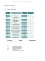
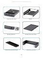
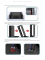
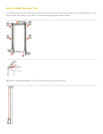
BOTTOM MOUNT INSTALLATION MANUAL iPAMM Installation Manual - BOTTOM MOUNT V1.0 Contents 1.0 iPAMM Models 4 1.1 iPAMM Plus 4 1.2 iPAMM Ready 4 1.3 RMS Capability 4 2.0Installation 5 2.1 What’s in the box 5 2.2Preparation 7 2.3Installation 7-11 1 iPAMM Data Sheet IMPORTANT NOTE Installation must be performed in accordance with the guidelines in the Installation Manual. Goto the SRA website www.server-racks-australia.com.au to download the latest documentation. SRA shall not be liable for any loss or damage direct or indirect or howsoever in relation to the fitness for use, merchantable quality or lack of correspondence with any sample or description or arising from the failure of the customer to satisfy itself that the goods supplied are of the description, quality and character ordered and gives no warranty as to the subsequent use of those goods under those specifications. SRA warrants all goods from faulty workmanship for a period of 12 months from the date of manufacture. SRA shall be limited in its liability to the replacement of or supply of equivalent goods. SRA shall not be liable for any loss or damage (including without limitation consequential loss, damage, injury or installation) resulting from the supply or use of such goods. The warranty does not apply to defects due to normal wear and tear, improper installation by persons other than SRA representatives, or to products or components thereof which are intentionally or negligently damaged or where products or components thereof have been subjected to operating or environmental conditions contrary to any applicable specifications or reasonable intended use. To ensure proper installation methods are followed we suggest using an SRA representative. For more information please contact SRA. SRA will be responsible (at SRA’s discretion) for the return of defective goods to SRA and delivery of replacement goods only to the extent of the original delivery. This warranty does not extend to any person other than the customer. 2 iPAMM Installation Manual - BOTTOM MOUNT V1.0 WELCOME Congratulations on becoming the proud owner of an iPAMM! We believe you have made the right choice and hope you will enjoy all of its capabilities. The iPAMM provides outstanding performance in all criteria of server racks – energy efficiency, reliability, security and price. This is achieved with a patented air management system which has been engineered and manufactured entirely in Australia. If you have any comments or feedback about our products or service in general please don’t hesitate to contact us. Our details are on the front page of this document. This document is subject to change without notice. We recommend obtaining the latest version from the Server Racks Australia website. The term iPAMM is used throughout this document and refers in the majority of cases to the collective family of iPAMM Ready, iPAMM and iPAMM Plus models. Caution The attached installation instructions should be read fully and followed to correctly install and setup the iPAMM. Failure to do so may damage the iPAMM and void the warranty. Care should be taken when lifting the rack and components as some items exceed the safe lifting limits permitted by one person. Disassembly of the rack and adherence to these instructions is required. 3 iPAMM Installation Manual - BOTTOM MOUNT V1.0 1.0 iPAMM Models The iPAMM comes in a top mount or bottom mount configuration. The bottom mount is suited to server rooms which have under floor cooling. The top mount is suited to server rooms which have above floor cooling. The whole room can be cooled or cool air can be ducted directly into the top of the iPAMM. Cooling is not essential; however, it increases the capacity of the iPAMM to remove heat from the rack. The top mount or bottom mount iPAMM comes in two models. These are described below. 1.1 iPAMM Ready The iPAMM Ready includes a plinth and sealed plenum. In the bottom mount configuration, when installed in a server room with under floor cooling, the plinth ducts the cool air directly into the front of the rack which pressurises the plenum. This cool air travels from the front to the rear of the rack which significantly increases the heat dissipation from the rack. The efficiency of the iPAMM is directly proportional to the pressure of the under floor air. The iPAMM Ready in top mount configuration with ducted cooling operates in a similar manner to the bottom mount configuration described. Due to the sealed plenum an iPAMM Ready should not be used in applications which do not have pressurised air entering the plinth. The iPAMM Ready offers significant increased cooling capacity compared to a standard (non-iPAMM) rack. The iPAMM Ready is fitted for but not with a controller and cassette. However, it is fitted with a docking station which quickly allows the iPAMM Ready to be upgraded to the iPAMM or iPAMM plus model. The plinth and docking station are not installed when shipped. A digital display showing the temperature within the rack is not a feature of the iPAMM Ready as it does not have a cassette. A controller and the RMS are not standard items delivered with the iPAMM Ready. However, a controller and the RMS can be installed to allow remote monitoring of the rack temperature. Monitoring the rack temperature provides the data to determine if the iPAMM Ready needs to be upgraded to an iPAMM or IPAMM Plus model. 1.2 iPAMM Plus The iPAMM Plus is identical to the iPAMM in all respects except that the cassette contains two fans which increases the cooling capacity. 1.3 RMS Capability All of the iPAMM models are capable of being fitted at the time of manufacture or post manufacture with the Remote Monitoring System (RMS). The RMS allows the remote monitoring of the rack temperature and for the iPAMM and iPAMM Plus it allows for the fan speed and fan duty cycle to be monitored. The maximum and minimum temperature settings can also be adjusted using the RMS. 4 iPAMM Installation Manual - BOTTOM MOUNT V1.0 2.0Installation 2.1 What’s in the box Part No. Component iPAMM Ready iPAMM Plus 1 Cable Entry Frame ● ● 2 Plinth ● ● 3 Front Cover ● 4 Cassete (2x fan) ● 5 Foam (white) ● ● 6 Docking Station ○ ● 7 Controller ○ ● 8 Controller with RMS ○ ○ 9 Temperature Sensor ○ ● 10 Serial Communication Cable ○ ● 11 Accessory Bag ● ● 12 Power Cord (2x - IEC to 3 pin) ● ● 13 Power Cord (x2 - IEC to IEC) ○ ○ 14 Safety Grill (B/M) ○ 15 Safety Grill (T/M) ○ 16 Ducting Grill (T/M) ○ ○ 17 Plinth Blanking Panel ○ ○ ● Standard ○ Option The contents of the Accessory Bag include: 12a 12b 12c 12d 12e 12f - - - - - - Cable ties (4) Thumb securing screw (1) M6 bolt and M6 washer (4) M6 bolt and m6 washer (6) 8g Tek screw (4) M5 button screw (4) or M5 nuts (4) 5 Not Applicable iPAMM Installation Manual - BOTTOM MOUNT V1.0 Cassette (2x fans) Plinth Docking Station Safety Grill with filter Cable Entry Baffle Panel Cable Entry Plinth 6 iPAMM Installation Manual - BOTTOM MOUNT V1.0 2.2Preparation a top mount iPAMM can be fitted with a ducting grill (optional). The location of the opening on the ducting grill is shown in the drawing at Annex B. 2.3Installation The components detailed in the previous table will be shipped with each iPAMM rack. The items will be packaged seperately within boxes contained inside the rack. The following tools are required to assemble the iPAMM. • Phillips No.2 screw driver • 8mm socket • 10mm socket Installation of the iPAMM components will take 20-30 minutes to complete. Place the iPAMM plinth down, being careful not to scratch or damage the paint. Take the Cable Plinth and fix it to the rear of the main plinth using 4 x M6 bolts and washers. Once secured carefully flip it over. 7 iPAMM Installation Manual - BOTTOM MOUNT V1.0 Install the filter panel/finger guard by slotting the tabs in as shown. Place the plinth in position over the removed tiles. Remove both doors from the rack to ensure they do not get damaged. With 2 people carefully tilt the rack backwards and slide it onto the top of the plinth until square. In the back of the rack on the bottom right side There are 3 auxilary connections. From left to right: RMS (silver port), Temperature sensor and HyperTerminal. Install the cables you as per your requirements. 8 iPAMM Installation Manual - BOTTOM MOUNT V1.0 Install the cable cover using 2x self tapping screws. Be careful not to pinch any of the cables. Using the blanking panel, cover the alternative docking station hole using 2x self tapping screws. Before inserting the insulating foam make sure the power cables for the docking station have been pulled through the cable plinth into the rack. Once through, push the foam into the large gap between the rear of the cabinet and the cable plinth. NOTE: It should be a tight fit. 9 iPAMM Installation Manual - BOTTOM MOUNT V1.0 With two people, lift the cassette and carefully allign the rails on the side of the cassette with the rails in the plinth. Once alligned slowly push the cassette into the plinth. Once the cassette has been fitted, insert the red top screw as shown. This secures the cassette in place. 10 iPAMM Installation Manual - BOTTOM MOUNT V1.0 NOTE The iPAMM is a SCEC compliant cabinet, however installation and cabling must be carried out to SCEC stanards to maintain compliance. Once the installation is completed please refer to the following documents: For iPAMM Controller setup and operation - iPAMM Controller Setup For iPAMM RMS operation and setup - iPAMM RMS User Manual 11 iPAMM Installation Manual - TOP MOUNT V1.0 iPAMM Documentation Guide Document Number 1 2 3 4 5 6 7 8 Description iPAMM Technical Datasheet iPAMM Specification Guide Top Mount Installation Manual Bottom Mount Installation Manual iPAMM Controller Configuration iPAMM User Manual iPAMM Maintenance Firmware Update Guide Server Racks Australia T: (02) 6298 1855 F: (02) 6297 5503 E: [email protected] W: www.server-racks-australia.com.au


![TestBed User Manual [PDF/1177KB]](http://vs1.manualzilla.com/store/data/005689366_1-da15ee0f5e0f03b5bd1516fa499d012b-150x150.png)