1
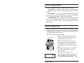
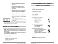
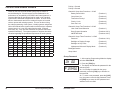
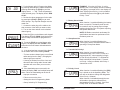
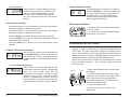
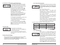
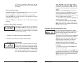
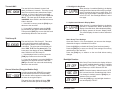
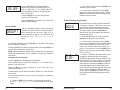
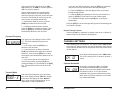
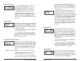
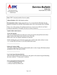
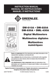
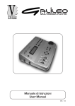
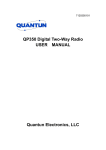
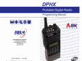
Contents
How to Program Radios ...................................................................... 3
Keypad Programming ......................................................................... 3
General Settings (Channel 0) ............................................................. 4
Group Password ............................................................................5
Automatic Numeric Identification (ANI) ..........................................6
Transmitter Time-Out Timer ...........................................................6
Scan Delay Time ............................................................................7
Priority 1 Channel ..........................................................................7
Priority 2 Channel ..........................................................................8
Channel 0 Group One Functions ...................................................8
Battery Saver Inhibit ...................................................................9
Group Scan List .........................................................................9
Transmit On Priority 1 ................................................................9
Priority 1 Lock ............................................................................9
Scan List Lock ..........................................................................10
Channel 0 Group Two Functions ..................................................10
User Code Guard Selection .....................................................10
Busy Channel Operation ..........................................................11
ANI/DTMF Mode ......................................................................11
Channel 0 Group Three Functions ...............................................12
Backlight On Display Change ..................................................12
Backlight On Key Press............................................................13
Alphanumeric/Numeric Display Mode ......................................13
Backlight Duration ........................................................................13
Group Labels................................................................................14
Review Channel 0 Values ........................................................15
RELM/BK Radio
1
Channel Settings ............................................................................... 15
Channel Bandwidth ......................................................................15
Receive Frequency ......................................................................16
Receive Mode ..............................................................................16
Receive Analog Code Guard .......................................................16
Receive NAC ................................................................................17
Squelch Mode ..............................................................................17
Transmit Frequency ......................................................................18
Transmit Mode..............................................................................18
Transmit Analog Code Guard.......................................................19
Transmit NAC ...............................................................................20
Talk Group ID ...............................................................................20
Secure Selection (Encrypted Radios Only)..................................20
Encryption Key (Encrypted Radios Only) .....................................21
Key Selection Setting (Encrypted Radios Only) ...........................22
Channel Label ..............................................................................22
Review Channel Settings .............................................................22
Program Another Channel ...........................................................23
Exit Programming Mode ..............................................................23
Cloning Radio Settings ..................................................................... 23
Special Cloning Instructions.........................................................25
Scan List Cloning .........................................................................26
CTCSS Code Guard Values .............................................................. 27
CDCSS Code Guard Values .............................................................. 28
Quick reference Guide - Channel 0 .................................................. 29
2
DPHx Programming Manual
How to Program Radios
There are three different ways to program BK Radio radios:
• BY KEYPAD A radio can be programmed with its keypad and
a programming plug, LAA0701. That procedure is described in this
section.
• BY CLONING You can transfer the programmed settings to
another radio of the same frequency band by using a cloning cable.
See "Cloning Radio Settings" on page 23 of this manual.
• BY COMPUTER With a computer, DPHx programming software,
and an LAA 0725 interface cable. That procedure is not described in
this manual. Contact BK Radio for the required programming cable
and software.
Keypad Programming
Radios are shipped with a door covering the keypad and display.
Before programming, remove the door by removing the battery pack,
engaging the door just below the speaker grill, and sliding the door
downward. Replace the battery pack.
Make sure the battery pack is charged.
Master Switch
Digital
ch
01
Programming
Plug
-- -- id
RELM/BK Radio
1. Insert the programming plug into the side
connector of the radio. The push-button
master switch will be on the top.
NOTE: The cloning cable can be used
as a substitute for the programming plug
by inserting the end with the push-button
master switch into the side connector of the
radio.
2. Select a channel group to be programmed
See "Select A Group/Channel” in the
Owner’s Manual.
3. Press and hold the master switch.
4. While holding the master switch, press and
hold the [FCN] key. After approximately
three seconds the LCD will display ‘- - - ID.’
3
5. Release the [FCN] key and the master
switch. The radio is now in the Password
Entry Mode.
6. Enter the six-digit password code for
the selected group. Without the correct
password code, you cannot proceed with
programming.
NOTE: New radios shipped from the factory
are assigned the password code 000000.
While entering the password code the
display will not change, but a beep will
sound for each key pressed. If the password
code is entered incorrectly, the radio will
reset to normal operation. Try again, starting
at step 2.
PRG
CH 00
7. Press the [ENT] key to proceed to
Programming Mode. The display will change
to PRG CH 00.
NOTE: Your radio may have been programmed to block keypad
programming access to some or all variables. Contact your BK Radio
Dealer if you need access to these fields.
GENERAL SETTINGS (CHANNEL 0)
Channel 0 settings for each group must be programmed separately.
NOTE: Settings listed as Group One Functions, Group Two Functions,
and Group Three Functions refer to programming function groups, not
channel groups.
Press the [FCN] key repeatedly to view the settings in Channel 0 and
then loop back to the CH 00 entry point.
QUICK REFERENCE GUIDE - CHANNEL 0
RADIO KEYPAD PROGRAMMING
Group Password
Automatic Numeric Identification (ANI)
Transmitter Time-Out Timer
Scan Delay Time
Priority 1 Channel
Priority 2 Channel
Channel 0 Group One Functions
Battery Saver Inhibit
Group Scan List
Transmit On Priority 1
Priority 1 Lock
Scan List Lock
Channel 0 Group Two Functions
User Code Guard Selection
Busy Channel Operation
ANI/DTMF Mode
1-12345
1-12345
1-12345
1-12345
1-12345
2-12345
2-12345
2-12345
Channel 0 Group Three Functions
Reserved for Future Enhancements
Backlight on Display Change
Backlight on Key Press
Alphanumeric/Numeric Display Mode
3-12345
3-12345
3-12345
3-12345
Backlight Duration
Group Label
Channel 0 settings include:
Group Password
Flashing number indicates active function.
Automatic Numeric Identification (ANI)
Transmitter Time-Out Timer
Scan Delay Time
4
DPHx Programming Manual
RELM/BK Radio
29
Priority 1 Channel
CDCSS CODE GUARD VALUES
Priority 2 Channel
Channel 0 Group One Functions: 1-12345
Codes for the CDCSS Code Guard system may be chosen fr
om the following list. Since there are no EIA standards for the
performance or compatibility of CDCSS Code Guard systems it is
recommended that an operational test be made on the intended
system before wholesale assignments are made. In some cases
either or both transmit and receive codes will require an inverted
code to operate with existing systems. This can be done during
the code programming of the system. Usually systems using direct
Unit-to-Unit transmission (systems without mobile relays, repeaters,
remote control, etc.) may use codes from the table. Systems
with relays, etc., may use code variations for systems control and
operational efficiency. The system operator or engineer should be
consulted regarding the operational requirement on such systems.
Battery Saver Inhibit
(Function 1)
Group Scan List
(Function 2)
Transmit on Priority 1
(Function 3)
Priority 1 Lock
(Function 4)
Scan List Lock
(Function 5)
Channel 0 Group Two Functions: 2-12345
User Code Guard Selection
(Function 1)
Busy Channel Operation
(Functions 2 & 3)
ANI/DTMF Mode
(Functions 4 & 5)
Channel 0 Group Three Functions: 3-12345
023
065
131
165
245
315
411
466
612
703
025
071
132
172
251
331
412
503
624
712
Reserved
(Functions 1 & 2)
026
072
134
174
261
343
423
506
627
723
Backlight on Display Change
(Function 3)
031
073
143
205
263
346
431
516
631
731
Backlight on Key Press
(Function 4)
032
074
152
223
265
351
432
532
632
732
043
114
155
226
271
364
445
546
654
734
Alphanumeric/Numeric Display Mode
(Function 5)
047
115
156
243
306
365
464
565
662
743
051
116
162
244
311
371
465
606
664
754
054
125
Backlight Duration
Group Label
Group Password
PRG
ch 00
PRG
p 123456
1. After entering Programming Mode the display
will show ‘PRG CH 00.’
2. Press the [FCN] key.
3. The display will indicate the password for the
selected group.
4a. If no change is needed for the group
password, press the [FCN] key to advance to
the next field.
4b. To enter a new password, press the [CLR]
key, then enter a new six-digit password. Press
the [ENT] key to store the new password and
advance to the next field.
28
DPHx Programming Manual
RELM/BK Radio
5
Automatic Numeric Identification (ANI)
PRG
ID
0000000
1. After the group password is set, the display
will indicate the ANI ID number (as many as
seven digits may be used). The ID number
can be used for either radio management
or transmitted as a DTMF tone burst for ANI
purposes. The ANI can be enabled or disabled.
See “ANI/DTMF Mode” on page 11 of this
manual.
2a. If no change is needed for the ID number,
press the [FCN] key to advance to the next field.
2b. To enter a new number, press the [CLR]
key and then the number keys. The digits will
appear at the right of display and move to the
left. Press the [ENT] key to store the new ID
number and advance to the next field.
Transmitter Time-Out Timer
CTCSS CODE GUARD VALUES
The CTCSS Code Guard system may be set for any frequency in
the range of 67 to 255.9 Hz. However, since most systems adhere
to the Electronic Industry Association (EIA) standards, tones should
be selected from the following EIA list. In order to insure optimum
performance, tone selection for use on the same radio frequency
(RF) channel or adjacent channels in the same coverage area
should be made from one of the Groups A, B, or C to the maximum
degree possible.
Group A
Group B
67.0 (XZ)
*151.4 (5Z)
77.0 (XB)
162.2 (5B)
88.5 (YB)
173.8 (6A)
*100.0 (1Z)
186.2 (7Z)
71.9 (XA)
Group C
146.2 (4B)
74.4
82.5 (YZ)
156.7 (5A)
79.7
94.8 (ZA)
167.9 (6Z)
85.4 (YA)
103.5 (1A)
*179.9 (6B)
91.5 (ZZ)
107.2 (1B)
203.5 (M1)
110.9 (2X)
192.8 (7A)
After the ID number is set, the display annunciators will indicate ‘PRG
TX.’ This is the duration of the transmitter Time-Out Timer. 0 SEC
means the Time-Out Timer is disabled.
114.8 (2A)
218.1 (M3)
*118.8 (2B)
210.7 (M2)
Press the [FCN] key to advance to the next field if no change is
needed.
141.3 (4A)
PRG TX
225 sec
1. Press the [PRI] key to increase the Time-Out
Timer duration by 15 seconds, with a maximum
of 225 seconds (3 minutes, 45 seconds). Press
the [PRI] key again to change the duration from
225 seconds to zero.
123.0 (3Z)
233.6
127.3 (3A)
225.7 (M4)
131.8 (3B)
250.3
136.5 (4Z)
241.8
* 50/60 Hz power distribution systems could cause falsing.
The assignments in a given area shall be made from within one of
the Groups: A, B, or C.
2. Press the [CLR] key to set the Time-Out
Timer duration to zero.
3. Press the [ENT] key to store the changed
setting and advance to the next field.
6
DPHx Programming Manual
RELM/BK Radio
27
NOTE: Any new number can be entered at this
point by pressing the [CLR] key and using the
digit keys to enter the new number.
PRG
clone
7. Press the [*] key. Connect the cable to the
second Clone and download by pressing [FCN].
8. Any number of radios can be coded with
different or sequential ID numbers using this
technique. The ID number in the permanent
memory of the Master radio will remain
unchanged as 100.
Scan Delay Time
After the Time-Out Timer is set, the upper display will indicate ‘PRG
SCN.’ This is the Scan Delay time in seconds.
Press the [FCN] key to advance to the next field if no change is
needed.
PRG
SCN
2.0 SEC
2. Press the [CLR] key to reset the scan delay
time to 0.
Scan List Cloning
When a Master radio downloads to a Clone, the Scan List is also
transferred. See the appropriate operating instructions in the
Owner’s Manual for changing the Scan List.
1. Press the [PRI] key to increase the scan
delay time by .5 seconds, up to 7.5 seconds.
Press the [PRI] key again to change the time
from 7.5 seconds to 0.
3. Press the [ENT] key to store the changed
setting and advance to the next field.
Priority 1 Channel
After the Scan Delay is set, the display will indicate ‘PRG PR1.’ The
Priority 1 Channel can be programmed as a fixed channel, tied to
the Channel Selector knob, or programmed OFF. If the radio is
programmed to transmit on the Priority 1 Channel, transmissions will
occur on PR1, if PR1 isn’t programmed OFF, when operating in Single
or Dual Priority Scan Mode.
If PR1 is a fixed channel, and the [PRI] key on the keypad is not locked
out, during normal radio operation the user can move the channel
selector to a new channel and press the [PRI] key to choose a new
PR1 channel.
PRG
PR 1 ON
1. Press the [PRI] key to cycle through the
priority channel options, or enter a fixed priority
channel using the number keys.
Setting the channel to ON ties the PR1 channel
to the Channel Selector knob. Pressing [CLR] or
the [0] key turns the PR1 channel OFF.
2. Press the [ENT] key to store the new priority
channel and advance to the next field.
26
DPHx Programming Manual
RELM/BK Radio
7
Priority 2 Channel
NOTE: To stop the ‘FAIL’ Mode, press [CLR],
turn off both radios, and try again, starting with
Step 1 on the previous page.
After the Priority 1 Channel is set, the display will indicate ‘PRG PR2.’
The Priority 2 Channel can be programmed as a fixed channel, tied to
the Channel Selector knob, or programmed OFF.
The PR2 channel cannot be altered during normal radio operation.
PRG
PR 2 OFF
Special Cloning Instructions
1. Press the [PRI] key to cycle through the
priority channel options, or enter a fixed priority
channel using the number keys.
It is possible to change Channel 0 values on the
Master radio, hold them in a temporary memory,
and download them to the Clone without actually
entering them into the permanent memory of the
Master radio. This is convenient for sequential
identification numbers used to identify a series
of portables in a radio system.
Setting the channel to ON ties the PR2 channel
to the Channel Selector knob. Pressing [CLR] or
the [0] key turns the PR2 channel OFF.
2. Press the [ENT] key to store the new priority
channel and advance to the next field.
Assuming that the frequencies, Code Guard
values, and other CH 0 values are common
for all radios in the system, but that the radio
identification number should be unique to each
radio, the following method would be used to
clone additional radios for the system.
Old-Style BK Priority Scan
The radio can be programmed to mimic the Old-Style BK Priority Scan
Modes as follows:
Mode
PR1
TX on PR1
PR2
A
On
No
Off
B
Fixed Channel #
No
Off
C
Fixed Channel #
Yes
Off
See “Priority Scan” in the Owner’s Manual for operational details of
the Old-Style BK Priority Scan Modes.
1. Program the Master radio with all
frequencies, Code Guard values, and Channel
0 values that will be common to all radios to be
cloned.
2. Advance the display to show the Master
radio's ID number - for example, 100.
PRG
ID
125
Channel 0 Group One Functions
PRG
1 -- 12345
After the Priority 2 Channel is set the display
will show ‘PRG 1-12345.’ This is a group of
five individual functions that can be enabled or
disabled.
When a function is enabled, the corresponding
number in the display will flash. When the
function is disabled the number is steady. If
you wish to change the function from enable
to disable or vice versa, press the number key
corresponding to that function.
8
DPHx Programming Manual
3. Press the [CLR] key; press 125. Do not
press the [ENT] key. Now 125 is in temporary
memory.
4. Press the [*] key, connect the cable to the
radios and download to the Clone by pressing
the [FCN] key. ID number 125 is now stored in
permanent memory of the Clone.
5. After download, press the [CLR] key on
the Master radio. Disconnect the Clone. The
Master radio display will show that 125 is still
being held in the temporary memory of the
Master radio.
PRG
ID
126
RELM/BK Radio
6. Press the [PRI] key. This will increment the
ID number one digit to 126.
25
PRG
ch 00
5. Put the Master radio in Programming Mode
by pressing and holding the master switch then
pressing and holding the [FCN] key until the
display shows ‘- - - ID.’ Enter the password
of the selected group. The display shows ‘PRG
CH 00.’
6. Review the values programmed in the radio
by pressing the [FCN] or [ENT] key at each
CHXX prompt. Any required changes must be
made now.
7. Connect the other plug of the cable to the
side connector of the radio you want to clone.
PRG
1 -- 12345
1. Battery Saver Inhibit
PRG
1 -- 12345
8. Turn on the clone and set it to the desired
channel group.
PRG
prog
PRG
clone
9. Press the [*] key on the Master radio keypad.
The display will flash ‘PROG’ signifying that the
radio is ready to download its program to the
clone.
10. Press the [FCN] key on the Master radio
keypad. The display will flash 'CLONE' while
information from the master is downloaded to
the clone.
11. If the download was successful, the display
on the master will resume flashing ‘PROG.’
• To clone another channel group, turn off both
radios and go back to Step 3, changing the
channel group as required.
fail
12. If the download was not successful, the
master will display ‘FAIL’ and multiple beeps will
follow. Failure of downloading can be due to:
• Improper connection
2. Group Scan List
PRG
1 -- 12345
PRG
1 -- 12345
When function 3 is enabled (flashing)
transmissions will occur on PR1, if PR1 isn’t
programmed OFF, when operating in Single
or Dual Priority Scan Mode. To simulate BK
Radio’s Old-Style Priority Mode C, Transmit
on Priority 1 must be enabled, with Priority 2
channel set to OFF.
4. Priority 1 Lock
PRG
1 -- 12345
When function 4 is enabled (flashing) the [PRI]
key is locked out in the Operating Mode. The
user will not be able to change the designation
of the Priority 1 Channel.
When function 4 is disabled (steady) the user
will be able to change the channel that is
designated as Priority 1 Channel. See “Dual
Priority Scan” in the Owner’s Manual.
• Setting the clone in Programming Mode
• Group ‘locked’ by PC Programming
DPHx Programming Manual
When function 2 is enabled (flashing) the
current group will be scanned when the radio is
operating in Group Scan Mode.
3. Transmit On Priority 1
• Failure to turn on the clone
24
When function 1 is enabled (flashing) the battery
saver is turned off. The battery saver should
be turned off only for getting proper voltage
readings during service or for systems requiring
fast squelch attack time.
NOTE: BK Radio current drain and battery life
specifications are based on performance with
the battery saver on.
• If cloning is finished, turn off the clone and
disconnect the cloning cable. Normal radio
operation will occur when you turn on the
clone.
PRG
EXAMPLE: If function 4 (Priority 1 Lock) is
disabled, the 4 in the display will not be flashing.
If the [4] key is pressed, the 4 in the display will
flash, signifying that Priority 1 Lock is enabled.
A subsequent press of the [4] key will disable
Priority 1 Lock.
RELM/BK Radio
9
Program Another Channel
5. Scan List Lock
PRG
1 -- 12345
When function 5 is enabled (flashing), the user
will not be able to change the channels in the
Scan List. When disabled (steady), the user
can enter or delete channels from the Scan
List. See “Change the Scan List” in the Owner’s
Manual.
Store Group One Settings
Once each function 1-5 is set as desired, you can store the changes,
discard the changes, or disable all 5 functions.
At the starting point for Channel 1, the display
will show ‘PRG CH 01’. Press the number keys
for another channel number to gain access to
the frequencies, etc. for that channel. Each
channel is then programmed using the same
steps described for Channel 1.
PRG
ch 01
Exit Programming Mode
CG-SQ
Once each function 1-5 is set as desired, you can store the changes,
discard the changes, or disable all 5 functions.
A
B
Press the [CLR] key to disable all Group One functions (steady).
C
OFF-VOL
6
5
4
3
7 8 9 10
11
12
13
14
2
15
1 16
1. Rotate the OFF-VOL knob counterclockwise
to the OFF position.
2. The radio will be in normal Operating Mode
the next time it is turned on.
Press the [ENT] key to store new Group One settings into memory
and advance to the next field.
Press the [FCN] key to advance to the next field without saving
changes.
Channel 0 Group Two Functions
PRG
2-- 12345
After Group One functions are set, the display will
show ‘PRG 2-12345’ for Group Two functions. As
with Group One functions, the enabled function
numbers will flash. The disabled functions remain
steady
1. User Code Guard Selection
PRG
2-- 12345
When function 1 is enabled (flashing) the user
will be able to press the keypad to independently
select the Code Guard values that are
programmed into Channels 1 through 16 while
operating on any Channel 1 through 16. When
function 1 is disabled the user will be unable to
use the keypad for Code Guard selection. See
"User Selected Code Guard" in Owner’s Manual.
CLONING RADIO SETTINGS
Any “Master” radio (a DPHx with the desired radio frequencies and
settings) is capable of transferring its program to another DPHx or
“slave” radio. The radio receiving the program is referred to as the
“clone.” The LAA0700 or E/GCC cloning cable will be required in the
following procedure. Contact your BK Radio dealer for information on
cloning between DPHx radios and other BK Radio products.
NOTE: Some groups may be “locked” by PC programming to prevent
them from being overwritten. Only “unlocked” groups will accept
incoming clones.
Master
Clone
Digital
Digital
SCN D
CMND
ch 01
RX
MHCMD
PROG|D
01
GROUP
PRG TX
RX SCN
D
CMND
ANNEL
HOME CH
ch 01
PRG TX
Master Switch
1. Make sure the battery packs for both radios
are charged.
2. Attach the master switch end of the cloning
cable to the side connector of the Master radio.
NOTE: One plug of the cloning cable has a
push-button master switch. This plug must be
attached to the Master radio.
3. Turn on the Master radio.
4. Select the group to be cloned from the
Master radio.
10
DPHx Programming Manual
RELM/BK Radio
23
Key Selection Setting (Encrypted Radios Only)
PRG
TX
ID
key -- xxx
In radios equipped with DES/AES encryption,
the next field is the Encryption Key Selection
setting. This selection will not appear in radios
that do not have the encryption option.
The upper line of the display will show ‘PRG
TX ID’, and the lower part of the display will
show ‘KEY-XXX’, where XXX can be ‘SEL’, for
selectable or 'LCK', for locked.
2 & 3. Busy Channel Operation
PRG
2-- 12345
Busy Channel Modes include:
Busy Channel Indicator - The yellow LED
illuminates when a signal is received on the
channel selected, with or without the programmed
receive Code Guard setting.
If the selection is set to Selectable, the
encryption key can be selected via the radio's
keypad. If the selection is set to Locked, this
channel will always use the encryption key
selected in the previous setting.
Busy Channel Lockout - The yellow LED
illuminates and the transmitter PTT is disabled
when a signal is received without the programmed
receive Code Guard setting.
For information on selectable key operation refer
to your radio's owner/user manual.
Busy Channel Override - This function is similar
to Busy Channel Lockout except the transmitter
PTT can be activated by rotating the Squelch
knob clockwise off the Code Guard detent.
1. If this setting is correct, press the [FCN] key
to advance to the next field.
2. If a new mode is desired, press the [PRI]
key to cycle through the mode settings. Press
[ENT] to store the new mode and automatically
advance to the next field.
To set Busy Channel operation, use the following chart:
Channel Label
PRG
LABEL
The last field is the channel label.
1. If this label is correct, press the [FCN] key to
proceed to the entry point.
2. If a new channel label is desired, follow the
instructions under "Group Labels" on page 14 of
this manual.
Review Channel Settings
Busy Channel
Function 2
Function 3
Indication
Disable (Steady)
Enable (Flashing)
Lockout
Enable (Flashing)
Enable (Flashing)
Override
Enable (Flashing)
Disable (Steady)
4 & 5. ANI/DTMF Mode
PRG
2-- 12345
After the channel label is set, the display will return to the Channel
1 starting point. If you wish to review the Channel 1 settings,
subsequent pressing of the [FCN] or [ENT] key will show each value
and then return to the Channel 1 starting point.
22
DPHx Programming Manual
Functions two and three are used to set Busy
Channel operation. There are three types of busy
channel operation available. They are described
more fully under "Busy Channel" in the Owner’s
Manual.
When function 4 is enabled (flashing) the ANI
ID number will be transmitted (as a DTMF tone
sequence) with each press of the PTT switch.
See "Automatic Numeric Identification (ANI)" on
page 6 of this manual for instructions on setting
the ANI number.
When function 5 is enabled (flashing) the keypad
becomes active for manual DTMF operation.
When functions 4 and 5 are both enabled (flashing)
the ANI tone sequence will be transmitted only
after the [ENT] key is pressed while the transmit
RELM/BK Radio
11
PTT switch is activated. A sidetone of the ANI
number transmitted will also be heard through
the speaker.
show ‘SEC-XXX’, where XXX can be ‘CLR’ to
always transmit a clear signal, ‘ENC’ to always
transmit an encrypted signal or 'SW' where the
tranmission can be selected via a programmed
switch.
Store Group Two Settings
NOTE: To use the 'SW' selection one of the
radios toggle switches or [FCN] menu selection
must be programmed with for the 'Transmit
Secure' selection. These settings require the use
of the PC Radio Editor LAA0744X.
Once each function 1-5 is set as desired, you can store the changes,
discard the changes, or disable all 5 functions.
Press the [CLR] key to disable all Group Two functions (steady).
Press the [ENT] key to store new Group Two settings into memory
and advance to the next field.
1. If the mode is correct, press the [FCN] key to
advance to the next field.
Press the [FCN] key to advance to the next field without saving
changes.
2. If a new mode is desired, press the [PRI]
key to cycle through the mode settings. Press
[ENT] to store the new mode and automatically
advance to the next field.
Channel 0 Group Three Functions
PRG
3-- 12345
After Group Two functions are set, the display will
show ‘PRG 3-12345’ for Group Three functions.
As with Group One and Group Two functions, the
enabled function numbers will flash. The disabled
functions remain steady.
Encryption Key (Encrypted Radios Only)
PRG
TX
ID
key 01
1. Function 1 is reserved for future enhancements.
The upper line of the display will show ‘PRG TX
ID’, and the lower part of the display will show
‘KEY-XX’, where XX can be ‘01’ to '32'. This is
the encryption key assigned to the channel.
2. Function 2 is reserved for future enhancements.
NOTE: Available encryption keys must be
loaded into the radio using a compatable
keyloader and enabled via the PC Radio Editor
LAA0744X.
3. Backlight On Display Change
PRG
2-- 12345
12
When function 3 is enabled (flashing), the display
backlight will illuminate each time the display
receives input. This includes displayed changes
in the selected channel or scan channel, and the
PR, TX, and SCN annunciators. The display will
not illuminate if backlight duration is set to LITE
OFF. See "Backlight Duration" on the next page.
DPHx Programming Manual
In radios equipped with DES/AES encryption,
the next field is the Encryption Key setting. This
selection will not appear in radios that do not
have the encryption option.
1. If the key is correct, press the [FCN] key to
advance to the next field.
2. If a new key is desired, press the [PRI] key to
increase the key number by 1 or use the keypad
numbers to select the deired key number. Press
[ENT] to store the new mode and automatically
advance to the next field.
RELM/BK Radio
21
Transmit NAC
PRG
TX
4. Backlight On Key Press
ID CG
NAC XXXX
The next field is the Network Access Code
(NAC) for Channel 1 transmit. This value is only
used if the transmit mode selected was Digital
or Mixed, or if User Code Guard is activated.
The upper part of the display will show ‘PRG TX
ID CG’. The lower part of the display will show
‘NACXXXX’ where XXXX is the Network Access
Code in decimal.
1. If the NAC is correct, press the [FCN] key to
advance to the next field.
2. If a new NAC is desired, press the [CLR]
key followed by the digits of the desired NAC.
Then press the [ENT] key to store this NAC and
automatically advance to the next field.
Talk Group ID
TX
ID
tg XXXXx
The next field is the Talk Group ID. This value
is only used if the transmit mode selected
was Digital or Mixed, or if User Code Guard
is activated. The upper part of the display will
show ‘PRG TX ID’ and the phone icon. The
lower part of the display will show ‘TGXXXXX’
where XXXXX is the Talk Group ID.
1. If the displayed value is correct, press the
[FCN] key to advance to the next field.
2. If you wish to change it, press the [CLR] key
followed by the digits for the new TGID, then
[ENT] to store the new value and automatically
advance to the next field.
Secure Selection (Encrypted Radios Only)
PRG
TX
ID
sec -- xxx
In radios equipped with DES/AES encryption,
the next field is the Secure Transmit setting.
This selection will not appear in radios that do
not have the encryption option.
The upper line of the display will show ‘PRG
TX ID’, and the lower part of the display will
20
2-- 12345
When function 4 is enabled (flashing), the display
backlight will illuminate each time a key is pressed,
even if pressing the key has no other effect. The
display will not illuminate if backlight duration is
set to LITE OFF. See "Backlight Duration" on the
next page.
5. Alphanumeric/Numeric Display Mode
PRG
2-- 12345
When function 5 is enabled (flashing), the display
operates in Alphanumeric Mode, enabling the
display of channel labels. When disabled (steady),
the display operates in Numeric Display Mode.
This mode displays channel numbers instead of
labels.
Store Group Three Settings
PRG
PRG
DPHx Programming Manual
Once each function 1-5 is set as desired, you can store the changes,
discard the changes, or disable all 5 functions.
Press the [CLR] key to disable all Group Three functions (steady).
Press the [ENT] key to store new Group Three settings into memory
and advance to the next field.
Press the [FCN] key to advance to the next field without saving
changes.
Backlight Duration
PRG
lITE OFF
PRG
1 SEC ON
PRG
lITE OFF
RELM/BK Radio
After Group Three functions, the display will show
the current backlight duration setting. Available
settings are LITE OFF, 1 SEC ON, 1-second
increments up to 6 SEC ON and LITE ON.
NOTE: Excessive battery drain will result if LITE
ON is set and used for extended periods of time.
If no change is needed, press the [FCN] key to
advance to the next field.
Press the [CLR] key to set backlight duration to
zero and display LITE OFF.
13
PRG
lITE OFF
Press the [PRI] key to increase backlight
duration by 1 second increments from LITE
OFF, to 1 SEC ON, 2, 3, 4, 5, 6 SEC ON, LITE
ON (illumination remains on constantly) then
back to LITE OFF.
1. If the mode is correct, press the [FCN] key to
advance to the next field.
2. If a new mode is desired, press the [PRI]
key to cycle through the mode settings. Press
[ENT] to store the new mode and automatically
advance to the next field.
Press the [ENT] key to store changes and
advance to the next field.
Press the [FCN] key to advance to the next field
without storing changes.
Transmit Analog Code Guard
PRG
Group Labels
PRG
GROUP 1
After the backlight duration setting, the display
will show the current label for the channel group.
Each channel group can have a label of up to
eight characters or spaces. The characters can
include 0-9, A-Z, -, *, $, /, +, %, \, |, _, <, >, h, or
blank.
TX
000.0
CG
1. If the displayed value is correct, press the
[FCN] key to advance to the next field.
2. If a new value is desired, press the [CLR]
key to reset the display to 0.0. Press the number
keys 0 thru 9 to enter a CTCSS Code Guard
value. See "CTCSS Code Guard Values" on
page 27 of this manual. Press the [ENT] key to
store the new value and automatically advance
to the next field.
If no change is needed, press the [FCN] key to go back to the starting
point for Channel 0 settings.
Press the [CLR] key to erase the current label. Press the [CLR] key a
second time to restore the current label.
NOTE: Special software available from BK Radio lets you enter group
labels and channel labels from a computer. Contact your dealer for
information.
Changing The Group Label
Press the [CLR] key. The display becomes blank.
The next field is the Analog Code Guard value
for Channel 1 transmit. This value is only used
if the transmit mode selected was Analog or
Mixed, or when User Code Guard is activated.
The upper display will show ‘PRG TX CG’
and the lower part of the display will show the
programmed guard.
PRG
TX
D 131--
Press number keys to enter 0-9 in positions 1-7. The digits start in
position 7, then move left.
Press the [#] key to toggle a decimal on or off to the right of the
character in position 7.
The decimal moves left with the number in position 7 as new numbers
are entered.
Use the following steps to enter a number in position 8 or characters
in positions 1-8:
CG
3. To enter a CDCSS Code Guard value press
the [#] key, causing the letter ‘D’ to appear
followed by three zeros. Enter the desired code
using keys 0 thru 7 (keys 8 & 9 do not respond).
See "CDCSS Code Guard Values" on page 28
of this manual. Pressing the [PRI] key after the
three-digit code has been entered allows the
code to be inverted (a dash appears to the right
of the number). When the displayed value is
correct, press the [ENT] key to store the Code
Guard value and automatically advance to the
next field.
a. Press the [PRI] key repeatedly to cycle through characters
0-9, A-Z, -, *, $, /, +, %, \, |, _, <, >, h, blank, then back to the start
again.
14
DPHx Programming Manual
RELM/BK Radio
19
The lower part of the display will show ‘SQLXXX’ where XXX is ‘NRM’ for normal squelch or
‘SEL’ for selective squelch.
If you pass the desired character, press the [PRI] key repeatedly
until you return to the start and reach that character again.
b. Press the [FCN] key to shift the display left by one position,
leaving position 8 blank.
Normal squelch opens on a matching NAC
and any Talk Group ID or Individual Unit ID.
Selective squelch requires the correct NAC and
the correct Talk Group ID, and for Unit-to-Unit
calls, requires a matching Individual ID.
1. If the Squelch Mode is correct, press the
[FCN] key to advance to the next field.
2. If a different Squelch Mode is desired,
press the [PRI] key to toggle the setting. Then
press the [ENT] key to store this setting and
automatically advance to the next field.
c. Press the [PRI] key repeatedly to enter the next character, or
press the [FCN] key a second time to enter a blank space.
d. To abandon changes, press the [CLR] key, restoring the
original label.
Press the [ENT] key to store changes and go back to the starting point
for Channel 0 settings.
Review Channel 0 Values
Press the [FCN] key repeatedly to display each value in Channel 0,
and then return to the Channel 0 starting point.
Transmit Frequency
PRG
TX
151.62500
The upper part of the display will show ‘PRG
TX.’ This is the transmitter frequency for
Channel 1.
1. If it is correct, press the [FCN] key to
advance to the next field.
2. If a new frequency is desired, press the
[CLR] key followed by the digits of the desired
frequency. Then press the [ENT] key to store
this frequency and automatically advance to the
next field.
3. If you want to operate this channel as a
receive-only channel, press the [CLR] key
(setting the display to 0.0) followed by the [ENT]
key. The transmitter will be locked off for this
channel.
Transmit Mode
PRG
TX
mode-- x
18
CHANNEL SETTINGS
At the starting point for Channel 0, the display shows ‘PRG CH 00.’
At this point, a channel number can now be pressed to allow access
to per-channel variables such as frequencies and Code Guard values
for that channel.
PRG
CH 01
Channel Bandwidth
PRG
CH 01N
After the transmit frequency is set, the upper
part of the display will show ‘PRG TX’, and the
lower part of the display will show ‘Mode-X’,
where X can be ‘A’ for Analog Mode, ‘D’ for
Digital Mode, or ‘M’ or Mixed Mode.
DPHx Programming Manual
Press [1] and the display will show ‘PRG CH 01.’
This is the starting point for entering channel 1
values.
RELM/BK Radio
At this point, pressing the [#] key will toggle
the channel's bandwidth setting. An 'N' will
appear to the right of the channel number when
the channel is set for 12.5/15 kHz channel
bandwidth using the narrow band receiver filter.
When there is no 'N' the channel is set for 25/30
kHz channel bandwidth.
15
Receive Frequency
PRG RX
151.62500
keys 0 thru 9 to enter a CTCSS Code Guard
value. See "CTCSS Code Guard Values" on
page 27 of this manual. Press the [ENT] key to
store the new value and automatically advance
to the next field.
1. Press the [FCN] key and the upper part of
the display will show ‘PRG RX.’ This is the
receive frequency for channel 1 (in MHz).
2. If the displayed frequency is correct, press
the [FCN] key to advance to the next field.
3. If a new frequency is desired, press the
[CLR] key followed by the digits of the desired
frequency. Then press the [ENT] key to store
this frequency and automatically advance to the
next field.
PRG RX
D 131--
CG
Receive Mode
PRG RX
MODE -- X
After the receive frequency is set, the upper part
of the display will show ‘PRG RX’, and the lower
part of the display will show ‘Mode-X’, where X
can be ‘A’ for Analog Mode, ‘D’ for Digital Mode,
or ‘M’ for Mixed Mode.
1. If the mode is correct, press the [FCN] key to
advance to the next field.
2. If a new mode is desired, press the [PRI]
key to cycle through the mode settings. Press
[ENT] to store the new mode and automatically
advance to the next field.
Receive NAC
PRG RX
ID CG
NAC XXXX
000.0
CG
The next field is the Analog Code Guard value
for Channel 1 receive. This value is only used if
the receive mode selected was Analog or Mixed,
or if User Code Guard is activated. The upper
display will show ‘PRG RX CG' and the lower
part of the display will show the programmed
guard.
NOTE: 0.0 indicates carrier squelch operation (no Code Guard).
1. If the displayed value is correct, press the
[FCN] key to advance to the next field.
2. If a new NAC is desired, press the [CLR]
key followed by the digits of the desired NAC.
Then press the [ENT] key to store this NAC and
automatically advance to the next field.
Squelch Mode
PRG RX
ID
sqL -- XXX
2. If a new value is desired, press the [CLR]
key to reset the display to 0.0. Press the number
16
DPHx Programming Manual
The next field is the Network Access Code
(NAC) for Channel 1 receive. This value is only
used if the receive mode selected was Digital or
Mixed, or if User Code Guard is activated. The
upper part of the display will show ‘PRG RX ID
CG’. The lower part of the display will show
‘NACXXXX’ where XXXX is the Network Access
Code in decimal.
1. If the NAC is correct, press the [FCN] key to
advance to the next field.
Receive Analog Code Guard
PRG RX
3. To enter a CDCSS Code Guard value press
the [#] key, causing the letter ‘D’ to appear
followed by three zeros. Enter the desired code
using keys 0 thru 7 (keys 8 & 9 do not respond).
See "CDCSS Code Guard Values" on page 28
of this manual. Pressing the [PRI] key after the
three-digit code has been entered allows the
code to be inverted (a dash appears to the right
of the number). When the displayed value is
correct, press the [ENT] key to store the Code
Guard value and automatically advance to the
next field.
RELM/BK Radio
The next field is the Receiver Squelch Mode
for Channel 1. This setting is only used if the
receive mode selected was Digital or Mixed, or
if User Code Guard is activated. The upper part
of the display will show ‘PRG RX ID’.
17