1
REV1.0
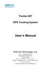
GSM/GPRS Shield with GPS
Receiver PA6E-CAM
GSM/GPRS Shield with GPS
Receiver PA6E-CAM
USER MANUAL
www.researchdesignlab.com
Page 1
REV1.0
GSM/GPRS Shield with GPS
Receiver PA6E-CAM
Contents
Overview......................................................................................................................................... 4
Features ........................................................................................................................................... 5
GSM/GPRS Shield Features ....................................................................................................... 5
GPS Receiver PA6E-CAM Features .......................................................................................... 5
Datasheets ....................................................................................................................................... 5
GSM Utility Software ..................................................................................................................... 6
Basic AT Commands for Testing ................................................................................................... 7
GSM AT Commands: ................................................................................................................. 7
GPRS Commands: ...................................................................................................................... 8
MODULE SETUP .......................................................................................................................... 9
For TESTING GSM/GPRS......................................................................................................... 9
FOR TESTING GPS................................................................................................................. 11
INDIVIDUAL ARDUINO TESTING CODES............................................................................ 12
GPRS CODE............................................................................................................................. 12
http://researchdesignlab.com/projects/google_gprs.zip................................................... 12
GPS CODE ............................................................................................................................... 12
GPS_GPRS_PHP_GOOFLE MAPS CODE ............................................................................ 12
POWER MODES.......................................................................................................................... 14
Power down mode..................................................................................................................... 14
Minimum Functionality Mode.................................................................................................. 14
Sleep mode................................................................................................................................ 14
Wake up SIM900A from sleep mode ....................................................................................... 14
GSM/GPRS Shield with GPS Receiver PA6E-CAM................................................................... 15
CIRCUIT DIAGRAM .................................................................................................................. 16
BLOCK DIAGRAMS................................................................................................................... 17
INTERFACING UNO AND GSM SHIELD............................................................................ 17
GSM SAMPLE CODES ............................................................................................................... 18
ARM CODE.............................................................................................................................. 18
ATMEL CODE......................................................................................................................... 18
www.researchdesignlab.com
Page 2
REV1.0
GSM/GPRS Shield with GPS
Receiver PA6E-CAM
PIC CODE ................................................................................................................................ 18
ARDUNIO CODE .................................................................................................................... 18
RASPBERRY PI CODE........................................................................................................... 18
BEAGLEBONE CODE ............................................................................................................ 18
MSP430 CODE......................................................................................................................... 18
GSM POWER SAVING ATMEL CODE ................................................................................ 18
GSM POWER SAVING PIC CODE........................................................................................ 18
MODULE HANDLING ............................................................................................................... 19
DO'S AND DONT'S ................................................................................................................. 19
www.researchdesignlab.com
Page 3
REV1.0
GSM/GPRS Shield with GPS
Receiver PA6E-CAM
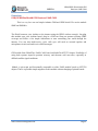
Overview
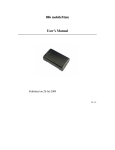
GSM/GPRS Shield with GPS Receiver PA6E-CAM
This is a very low cost and simple Arduino GSM and GPRS shield. We use the module
SIMCom SIM900A.
The Shield connects your Arduino to the internet using the GPRS wireless network. Just plug
this module onto your Arduino board, plug in a SIM card from an operator offering GPRS
coverage and follow a few simple instructions to start controlling your world through the
internet. You can also make/receive voice calls (you will need an external speaker and
microphone circuit) and send/receive SMS messages.
GPS module from GlobalTop: PA6E-CAM, based on MediaTek MT3333 chipset. Possibility of
using both systems improves position accuracy and shortens cold start time, especially in
difficult satellite signal conditions.
Module is pin-to-pin and functionally compatible to older PA6E module based on MT3329
chipset. Thus it is possible simple migration to this module without changing of printed boards.
www.researchdesignlab.com
Page 4
REV1.0
GSM/GPRS Shield with GPS
Receiver PA6E-CAM
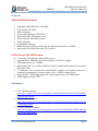
Features
GSM/GPRS Shield Features
Dual-Band GSM/GPRS 900/ 1800 MHz
TTL data(RX,TX,GND).
ESD Compliance.
Power controlled using 29302WU IC.
Enable with MIC and SPeaker socket.
SMA connector with GSM Antenna
SIM Card holder.
Configurable baud rate
Inbuilt Powerful TCP/IP protocol stack for internet data transfer over GPRS.
High quality PCB FR4 Grade with FPT Certified.
GPS Receiver PA6E-CAM Features
33 tracking/ 99 acquisition-channel GPS receiver.
Supports QZSS, SBAS(WAAS, EGNOS, MSAS, GAGAN*) ranging.
Ultra-High Sensitivity: -165dBm.
High Update Rate: up to 10Hz(: SBAS can only be enabled when update rate is equal or
less than to 5Hz.).
12 multi-tone active interference canceller(Some features need special firmware or
command programmed by customer please refer to “PMTK Command List”)
High accuracy 1-PPS timing support for Timing Applications (±10ns RMS jitter).
AGPS Support for Fast TTFF.
Datasheets
AT Commands datasheet
https://drive.google.com/a/researchdesignlab.com/file/d/0BzrGD4zr88GnTkJwSll3dnhK
bTg/edit?usp=sharing
FTP Commands datasheet
https://drive.google.com/a/researchdesignlab.com/file/d/0BzrGD4zr88GnVkhacjUtY2tIU
2c/edit?usp=sharing
TCP/IP Commands datasheet
https://drive.google.com/a/researchdesignlab.com/file/d/0BzrGD4zr88GnUHRCQlJwUjd
WTVU/edit?usp=sharing
www.researchdesignlab.com
Page 5
REV1.0
GSM/GPRS Shield with GPS
Receiver PA6E-CAM
GSM Utility Software
Bulk Message sending
AT command testing terminal
Provides step by step GPRS setup
To download GSM/GPRS Utility software ,click on the link below
https://docs.google.com/file/d/0BzrGD4zr88GnYll6dlFJT2NFY2s/edit
http://www.4shared.com/file/rwyHmtGOba/GSM_GPRS_utility.html
www.researchdesignlab.com
Page 6
REV1.0
GSM/GPRS Shield with GPS
Receiver PA6E-CAM
Basic AT Commands for Testing
GSM AT Commands:
TO CHECK THE MODEM:
AT ↲
OK
TO CHANGE SMS SENDING MODE:
AT+CMGF=1 ↲
OK
TO SEND NEW SMS:
AT+CMGS=”MOBILE NO.” ↲
<MESSAGE
{CTRL+Z}
TO RECEIVE SMS
AT+CMGD=1 ↲
{to delete the message in buffer}
AT+CMGR=1 ↲
{to receive first message AT+CMGR=1}
{to receive second message AT+CMGR=2 and so on}
+CMGL: 1,"REC READ","+85291234567",,"07/05/01,08:00:15+32",145,37
<MESSAGE
PREFERRED SMS MESSAGE STORAGE:
AT+CPMS=? ↲
+CPMS: (“SM”),(“SM”),(“SM”)
OK
AT+CPMS? ↲
+CPMS: “SM”,19,30,”SM”,19,30,”SM”,19,30
TO MAKE A VOICE CALL:
ATD9876543210; ↲
TO REDIAL LAST NO:
ATDL ↲
TO RECEIVE INCOMING CALL:
ATA ↲
TO HANGUP OR DISCONNECT A CALL:
ATH ↲
TO SET A PARTICULAR BAUDRATE:
AT+IPR=? ↲
{To view the baud rate values}
AT+IPR=0 ↲
{To set the modem to autobauding mode}
OPERATOR SELECTION:
AT+COPS=? ↲
OK
AT+COPS? ↲
+COPS: 0,0,”AirTel”
OK
www.researchdesignlab.com
Page 7
REV1.0
GSM/GPRS Shield with GPS
Receiver PA6E-CAM
AT+CRC SET CELLULAR RESULT CODES FOR INCOMING CALL INDICATION:
AT+CRC=? ↲
+CRC: (0-1)
OK
AT+CRC? ↲
+CRC: 0
OK
AT+CRC=1 ↲
OK
+CRING: VOICE
READ OPERATOR NAMES.
AT+COPN=? ↲
OK
AT+COPN ↲
+COPN: “472001″,”DHIMOBILE”
+COPN: “60500
+COPN: “502012″,”maxis mobile”
+COPN:
+COPN: “502013″,”TMTOUCH”
+COPN
+COPN: “502016″,”DiGi”
+COPN: “502017″,”TIMECel”"
+COPN: “502019″,”CELCOM GSM”
GPRS Commands:
Command
AT+CGATT ↲
AT+CGDCONT ↲
AT+CGQMIN ↲
AT+CGQREQ ↲
AT+CGACT ↲
AT+CGDATA ↲
AT+CGPADDR ↲
AT+CGCLASS ↲
AT+CGEREP ↲
AT+CGREG ↲
AT+CGSMS ↲
AT+CGCOUNT ↲
Description
ATTACH/DETACH FROM GPRS SERVICE
DEFINE PDP CONTEXT
QUALITY OF SERVICE PROFILE (MINIMUM ACCEPTABLE)
QUALITY OF SERVICE PROFILE (REQUESTED)
PDP CONTEXT ACTIVATE OR DEACTIVATE
ENTER DATA STATE
SHOW PDP ADDRESS
GPRS MOBILE STATION CLASS
CONTROL UNSOLICITED GPRS EVENT REPORTING
NETWORK REGISTRATION STATUS
SELECT SERVICE FOR MO SMS MESSAGES
GPRS PACKET COUNTERS
www.researchdesignlab.com
Page 8
REV1.0
GSM/GPRS Shield with GPS
Receiver PA6E-CAM
MODULE SETUP
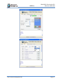
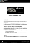
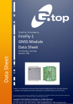
For TESTING GSM/GPRS
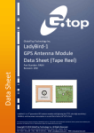
step 1 : Insert SIMcard into the SIM slot.
step 2 : Plug in 12V -2A DC power adapter, power led is lit (place jumper in JP3,to turn ON
automatically ).
step 3 : Press and hold power button (To turn on manually without jumper)
step 4 : Connect to PC through TTL TO USB converter (connect RX(D0) and TX(D1))
step 5 : open GSM/GPRS utility software ,choose appropriate COM port and use AT commands
listed in this manual for basic testing GPRS GSM/messaging and voice calling.
www.researchdesignlab.com
Page 9
REV1.0
www.researchdesignlab.com
GSM/GPRS Shield with GPS
Receiver PA6E-CAM
Page 10
REV1.0
GSM/GPRS Shield with GPS
Receiver PA6E-CAM
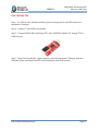
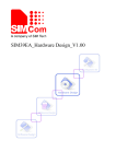
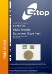
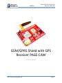
FOR TESTING GPS
Step 1 : For GPS to work, Module should be placed in an open space until GPS locks on to
minimum of 4 satellite .
Step 2 : Connect 5V and GND to the module
Step 3 : Connect D2(Soft RX) and D3(soft TX) of the GSM/GPS shield to PC through TTL to
USB converter
Step 3 : Open serial window(Ex : hyper terminal) ,select the appropriate COM port ,baud rate
9600,then all the serial data from GPS will be displayed in the serial window.
www.researchdesignlab.com
Page 11
REV1.0
GSM/GPRS Shield with GPS
Receiver PA6E-CAM
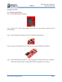
INDIVIDUAL ARDUINO TESTING CODES
GPRS CODE
http://researchdesignlab.com/projects/google_gprs.zip
GPS CODE
http://researchdesignlab.com/projects/gps.zip
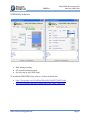
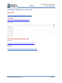
Screen shots
GPS_GPRS_PHP_GOOFLE MAPS CODE
Uno code
http://researchdesignlab.com/projects/uno
gps tracking.zip
PHP code
http://researchdesignlab.com/projects/PHP_GPS_GPRS_Code.zip
www.researchdesignlab.com
Page 12
REV1.0
GSM/GPRS Shield with GPS
Receiver PA6E-CAM
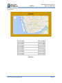
Screen shots
Data base
www.researchdesignlab.com
Page 13
REV1.0
GSM/GPRS Shield with GPS
Receiver PA6E-CAM
POWER MODES
Power down mode
SIM900A is set power down mode by “AT+CPOWD=0”
There are two methods for the module to enter into low current consumption status
Minimum Functionality Mode
Minimum functionality mode reduces the functionality of the module to a minimum and thus
minimizes the current consumption to the lowest level.
If SIM900A has been set to minimum functionality by “AT+CFUN=0”
If SIM900A has been set to full functionality by “AT+CFUN=1”
If SIM900A is set “AT+CFUN=4” to disable both the above functionality.
Sleep mode
We can control SIM900A module to enter or exit the SLEEP mode in customer
applications through DTR signal. When DTR is in high level and there is no on air and hardware
interrupt (such as GPIO interrupt or data on serial port), SIM900A will enter SLEEP mode
automatically. In this mode, SIM900A can still receive paging or SMS from network but the
serial port is not accessible.
Wake up SIM900A from sleep mode
Enable DTR pin to wake up SIM900A. If DTR pin is pulled down to a low level
This signal will wake up SIM900A from power saving mode. The serial port will be
active after DTR changed to low level for about 50ms.
Receiving a voice or data call from network to wake up SIM900A.
Receiving a SMS from network to wake up SIM900A.
www.researchdesignlab.com
Page 14
REV1.0
GSM/GPRS Shield with GPS
Receiver PA6E-CAM
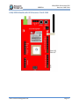
GSM/GPRS Shield with GPS Receiver PA6E-CAM
www.researchdesignlab.com
Page 15
REV1.0
GSM/GPRS Shield with GPS
Receiver PA6E-CAM
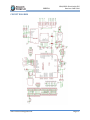
CIRCUIT DIAGRAM
www.researchdesignlab.com
Page 16
REV1.0
GSM/GPRS Shield with GPS
Receiver PA6E-CAM
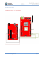
BLOCK DIAGRAMS
INTERFACING UNO AND GSM SHIELD
www.researchdesignlab.com
Page 17
REV1.0
GSM/GPRS Shield with GPS
Receiver PA6E-CAM
GSM SAMPLE CODES
ARM CODE
http://researchdesignlab.com/gsm-modem-arm-code
ATMEL CODE
http://researchdesignlab.com/gsm-modem-atmel-code
PIC CODE
http://forum.researchdesignlab.com/GSM%20SIM900/PIC/SIM900.c
ARDUNIO CODE
http://researchdesignlab.com/arduino-gsm2-code
RASPBERRY PI CODE
SENDING CODE
http://researchdesignlab.com/gsm-raspberry-code
RECEIVING CODE
http://researchdesignlab.com/gsm-raspberry-receiving-code.html
BEAGLEBONE CODE
SENDING CODE
http://researchdesignlab.com/gsm-beaglebone-send-code
RECEIVING CODE
http://researchdesignlab.com/gsm-beaglebone-receiving-code.html
MSP430 CODE
http://forum.researchdesignlab.com/MSP430/MSP/GSM.zip
GSM POWER SAVING ATMEL CODE
http://researchdesignlab.com/gsm-power-atmel-code.html
GSM POWER SAVING PIC CODE
http://researchdesignlab.com/gsm-power-pic-code.html
www.researchdesignlab.com
Page 18
REV1.0
GSM/GPRS Shield with GPS
Receiver PA6E-CAM
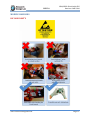
MODULE HANDLING
DO'S AND DONT'S
www.researchdesignlab.com
Page 19