1
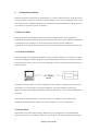
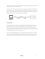
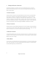
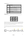
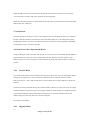
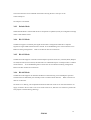
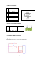
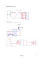
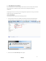
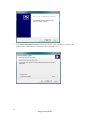
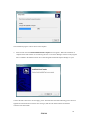
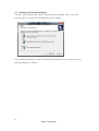
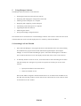
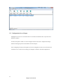
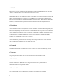
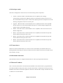
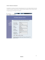
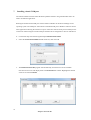
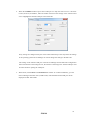
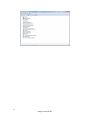
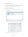
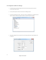
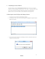
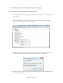
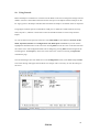
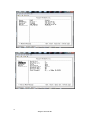
Ethernet Digital I/O Server
User Manual
Model Name: EIO-188
September 2013
1
Passport Networks Inc.
2
EIO188
1. INTRODUCTION………………………………………………………………..6
1.1
FEATURES………………………………………………………………………………....6
1.2
PRODUCT SPECIFICATIONS…………………………………………………………….7
1.3
DEFAULT SETTTINGS…………………………………………………………………….8
2. COMMUNICATION MODES…………………………………………………..9
2.1
DIRECT IP MODE………………………………………………………………………….9
2.2
VIRTUAL COM MODE……………………………………………………………………9
2.3
PAIRED MODE……………………………………………………………………………..9
2.4
HERART BEAT……………………………………………………………………………10
3. MAKING THE HARDWARE CONNECTIONS……………………………..11
3.1
SERIAL CONNECTION…………………………………………………………………..11
3.2
POWER CONNECTION…………………………………………………………………..11
3.3
ETHERNET CONNECTION……………………………………………………………...11
3.4
RESET BUTTON………………………………………………………………………….11
3.5
LED DEFINITION………………………………………………………………………...12
3.6
DIP SWITCES……………………………………………………………………………..12
3.7
SERIAL PORTS…………………………………………………………………………...13
3.8
SERIAL SERVER/PORT OPERATIONAL MODES……………………………………..13
3.9
3.8.1
Console mode…………………………………………………………………13
3.8.2
Upgrade mode………………………………………………………………...13
3.8.3
Default mode……………………………………………………………….....14
3.8.4
RS-232 mode…………………………………………………………………..14
3.8.5
RS-422 mode…………………………………………………………………..14
3.8.6
RS-485 mode…………………………………………………………………..14
DB9 PIN CONFIGURATION……………………………………………………………..15
3.10 5 PIN TERMINAL BLOCK CONFIGURATION…………………………………………15
3.11 DIGITAL I/O HARDWARD CONNECTION…………………………………………….15
3.12 DIGITAL I/O 30 PIN CONFIGURATION………………………………………………..17
4. EIO-188 SOFTWARE INSTALLATION……………………………………...18
4.1
NEW INSTALLATION……………………………………………………………………18
4.2
UPDATING AN EXISTING INSTALLATION…………………………………………...21
5. USING MANAGER SOFTWARE……………………………………………..22
5.1
SEARCHING LAN FOR EIO-188………………………………………………………..22
5.2
CONFIGURING SERVER PROPERTIES………………………………………………..23
6. SERVER PROPERTIES……………………………………………………….24
6.1
SERVER NAME…………………………………………………………………………..24
6.2
SERAL NUMBE…………………………………………………………………………..24
6.3
PASSWORD……………………………………………………………………………….24
3
Passport Networks Inc.
6.4
DHCP………………………………………………………………………………………25
6.5
IP ADDRESS………………………………………………………………………………25
6.6
NETMASK………………………………………………………………………………...25
6.7
GATEWAY………………………………………………………………………………...25
6.8
MAC ADDRESS…………………………………………………………………..............25
6.9
VERSION & DATE…………………………………………………………………..........25
6.10 LINK STATUS……………………………………………………………………………..26
6.11 SERVER SETIAL PORT…………………………………………………………………..26
6.12 BAUDRATE……………………………………………………………………………….26
6.13 DATA/PARITY/STOP……………………………………………………………………..26
6.14 FLOW CONTROL………………………………………………………………………...26
6.15 PROTOCOL……………………………………………………………………………….26
6.16 SERIAL TIMEOUT……………………………………………………………………….27
6.17 TCP ALIVE TIMEOUT……………………………………………………………………27
6.18 CONNECTION MODE……………………………………………………………………27
6.19 DELIMITER HEX1 AND DELIMITER HEX2…………………………………………..28
6.20 FORCE TRANSMIT………………………………………………………………………28
6.21 PORT STATUS…………………………………………………………………………….28
6.22 TCP/UDP PORT…………………………………………………………………………...28
6.23 SERIAL PORT MODE…………………………………………………………………….28
6.24 CONNECTION AT………………………………………………………………………...29
6.25 MAXIMUM CONNECTION……………………………………………………………...29
6.26 REMOTE IP ADDRESS…………………………………………………………………...29
6.27 UID………………………………………………………………………………………...29
6.28 UPDATE/SAVE……………………………………………………………………………30
6.28.1
Updating the Server Properties in Manager Software…………………………...30
6.28.2
Saving Configuration Data in Console Mode or telnet…………………………..30
6.28.3
Web Server Interface……………………………………………………………..32
7. INSTALLING VIRTUAL COM PORT……………………………………….33
8. CONFIGURING VIRTUAL COM PORT…………………………………….36
8.1
CONFIGURATION WITH MANAGER SOFTWARE…………………………………...36
8.2
CONFIGURATION WITH DEVICE MANAGER………………………………………..37
9. UNINSTALLING THE VIRTUAL COMPORT……………………………...38
9.1
REMOVING THE VIRTUAL COM PORT WITH MANAGER SOFTWARE…………..38
9.2
REMOVING THE VIRTUAL COM PORT USING DEVIC MANAGER……………….39
10. USING CONSOLE……………………………………………………………..40
11. USING TELNET………………………………………………………………..43
12. USING WEBSERVER………………………………………………………….44
4
EIO188
13. UPGRADING THE SERIAL SERVER FIRMWARE……………………….47
14. MODBUS COMMAND………………………………………………………...49
15. TROUBLESHOOTING
5
Passport Networks Inc.
1
Introduction
The EIO-188 Ethernet Digital I/O Server connects serial Devices and Support Digital I/O , Ethernet
LAN/WAN providing a reliable communication connection. Existing Windows based serial software
using standard Windows API does not have to be modified communicate over an Ethernet LAN to a
serial device. The EIO-188 virtual COM port will make this an easy transition
The EIO-188 operator in “Direct IP Mode”, “Virtual COM Mode”, and “Paired Mode”, EIO-188 has
one asynchronous DB-9 serial ports and one port control Digital I/O by MODBUS Command,
One 10/100 Mbps Ethernet RJ-45 connection. The Ethernet port will auto-select 10BaseT or
100BaseTX.
The EIO-188 Windows driver installs virtual COM ports in the Device Manager of the operating
system. The virtual COM port is designed to establish a connection with the EIO-188. This in turn will
allow communications with the connected serial device in the same manner as a device connected to
the COM port on a PC. The LAN becomes transparent to the serial device and the software running on
PC.
The EIO-188 can be configured as a TCP or UDP Client/Server. In direct IP and virtual COM modes,
EIO-188 should be configured as a server. EIO-188 also offers a Heart Beat feature to insure a reliable
communications connection.
1.1 Features
• DIN rail or Panel mount
• Supports 10/100 Mbps Ethernet
• Supports LAN and WAN communications
• In Server mode supports individual client sessions for security.
• Management access password protected
• Software for Windows NT/98/ME/2000/XP/Vista(x86 / x64)/Win7 (x86 / x64)
• Supports socket connection, TCP server, TCP client, and UDP.
• Supports up to 8 TCP connections in TCP server mode.
• Heart beat connection ensures reliable TCP connection against power failure or
network disruption.
• Supports slave mode. 1 EIO-188 which connect Ethernet could control 31 Slave mode
machine
• 2serial ports, Port1 do RS232/422/485 Communication, Port 2 could control
8 point digital I/O(RS232)
•8 point digital Input, dry contact or wet contact, 8 point digital output
6
EIO188
•Watch dog timer 1.34sec
1.2 PRODUCT SPECIFICATIONS
LAN:
10/100 Mbps Auto-detecting – 10 Base T,
100 Base TX
Serial Output/Input buffer:
Serial Interfaces:
64Kbyte
RS-232 - TX, RX, RTS, CTS, DTR, DSR,
DCD, GND
RS-422 - TX+, TX-, RX+, RX-, RTS+, RTS-,
CTS+, CTS-, GND
RS-485 - Data +, Data –, GND
Serial Connection:
DTE-DB9
Data Rate:
110 bps to 230.4 k bps
Parity:
none, even, odd, mark, space
Data Bits:
5, 6, 7 or 8
Stop Bits:
1, 1.5 or 2
Protocol:
TCP, IP, ARP, DHCP, Telnet, HTTP, UDP, ICMP
Digital I/O
8 point Input , Dry contact or Wet Contact
(8 DI/ 1power/1common)
8 point Output
(8 DO/8 CO/ 2 power / 2common)
Management:
Manager software, Serial Console, Telnet, Web server
Firmware upgradeable
Power Requirement
7 ~ 30VDC, 500mA
Operating Temperature:
0 to 70 °C (32 to 122 °F)
Storage Temperature:
-20 to 90 °C (-4 to 140 °F)
Humidity:
0 – 90% Non-Condensing
Dimension:
114mm*143mm*28mm (4.5 in*5.6in*1.1in)
Approvals:
CE, FCC
7
Passport Networks Inc.
1.3 Default Settings
Server name:
EIO-188
Serial number:
Fixed – see bottom label
Password:
Blank
DHCP:
Disable
IP address:
192.168.2.1
Netmask:
255.255.255.0
Gateway
:
192.168.1.254
MAC address:
Fixed – see bottom label
Version & Date:
current firmware version number and date
Baud rate:
Serial port1:9600, Serial port2:115200
Data/Stop bits:
8-1
Parity:
None
Flow control:
None
Protocol:
TCP
Serial timeout:
0 seconds
TCP alive timeout:
0 minutes
Connection mode:
Server
Delimiter HEX 1:
00
Delimiter HEX 2:
00
Force transmit:
0 ms
TCP/UDP port:
Port1:4000, Port2:4001
Serial port mode:
RS232
Maximum connection: 8
Remote IP address:
255.255.255.255
8
EIO188
2
Communication Modes
The EIO-188 allows serial devices to communicate over a LAN or Intranet network. Serial devices are
no longer limited to a physical connection to the PC COM port. They can be installed anywhere on the
LAN using TCP/IP or UDP/IP communications. This will also allow traditional PC COM ports access
to a serial device anywhere on the LAN network.
2.1 Direct IP Mode
Direct IP connections allow applications using TCP/IP or UDP/IP network socket programs to
communicate with the asynchronous serial port on the EIO-188. In this type of application the EIO-188
is configured to TCP or UDP server. The socket program running on the PC establishes a
communication connection with the EIO-188. The raw data is sent directly to and from the serial port.
2.2 Virtual COM Mode
The Virtual COM mode requires the installation of a driver. When installed a new COM port is added
to the Device Manager. Windows programs using standard Windows API calls will be able to interface
with Virtual ports. The PC will act as the host connecting to the EIO-188 when the program opens the
virtual COM port.
EIO-188
Once the connection is made, the LAN is transparent to the serial device. Applications work just as if
the serial device is connected a host’s physical COM port. The virtual COM port converts the
application’s data into IP packet destined for the EIO-188, which in turn converts the IP packet back to
serial data.
In this mode, the EIO-188 must be set to either TCP/server or UDP/server in the menu with a
designated communication port number. The virtual COM driver is a TCP or UDP client.
2.3 Paired Mode
Paired mode is also called serial tunneling. When this type of configuration is selected additional
software will not have to be loaded on a host PC. In fact a PC is not required to make the connection.
9
Passport Networks Inc.
Any two dumb serial devices that can communicate with each other through a serial link will be able to
communicate using two EIO-188 and the LAN.
Two EIO-188 are configured with one setup as a TCP or UDP client and the other to TCP/UDP server.
When setting up the Server, the Remote IP address section must contain the address of the Client. This
will allow the Client’s IP address to pass the IP address-filtering feature of the Server. Conversely, the
Remote IP address of the Client must contain the Server’s IP address.
EIO-188
EIO-188
2.4 Heart Beat
The EIO-188 provides a convenient way to establish reliable communications between two devices.
Communication port 5300 is reserved for the Heartbeat Protocol. Without this feature a device that
loses a connection and stops communicating would not be able to reconnect without personally
attending to the problem. A TCP data connection can be lost when there is a power failure or temporary
loss of an Ethernet connection on either the client or server.
If a loss occurs the Heart Beat feature will try to reconnect the TCP data connection every 5 seconds
until communications is established again. The Heart Beat feature is available to use with the Virtual
COM Mode, Paired Mode and Direct IP Mode. This is not available when using a UDP application.
10
EIO188
3
Making the Hardware Connections
The following information is provided to give the user an understanding of how to connect the
EIO-188 to the LAN and serial device. A review of the switch settings and the functionality of the
LED’s are also provided.
3.1 Serial Connection
The EIO-188 has two serial port, Port1 had one DB-9 male connector and one 5 pin terminal block
The serial port is configured as a DTE (data terminal equipment) device or Jump wire directly by
terminal block The serial port is configured as a DTE (data terminal equipment) device or . All PC
COM ports are DTE ports. A null modem cable is required to make a connection between the COM
port on a PC and the EIO-188 serial port. A straight through cable is required to connect the EIO-188
serial port to a DCE device. Port2 connect Digital IO MODBUS command micro controller
3.2 Power Connection
The EIO-188 has a two pins terminal block and power jack. Power can apply on either terminal block
or the power jack. It accepts 7VDC-30VDC 500mA power supply. When power is apply a green light
label as run will flash every one second to indicate the system is up and running.
3.3 Ethernet Connection
A straight-through Ethernet cable can be used to connect the serial server to an Ethernet hub, switch, or
wall plate. A crossover Ethernet cable can be used to make a connection directly to the NIC (Network
Interface Card) on a PC or laptop.
3.4 Reset Button
The reset button can be found between the switch and terminal block. To reset the unit manually apply
power, insert a small plastic tool, and press lightly depressing switch. Hold for 3 seconds and release.
The Link and Run light will go out and turn back on.
11
Passport Networks Inc.
3.5 LED Definition
Led Name Led Function
Link
Green – 100 BaseTX Ethernet connection established
Yellow – 10 BaseT Ethernet connection established
Run
Serial 1
Flashing Green – system is ready
Green – connection established
Flashing Green – data is transmitting
DI/DO
Green – connection established
Flashing Green – data is transmitting
DI1~DI8
Green – Status ON
DO1~DO8 Green – Status ON
3.6 Dip Switches
A double DIP switch allows the EIO-188 to be placed into Console/Slave/Default/Data Mode.
SW1
SW2
Mode
ON
ON
Console
ON
OFF
Slave
OFF
ON
Factory
OFF
OFF
Data
When all these switches are moved into the ON position, the EIO-188 enters Console Mode, allowing
configuration of the EIO-188 from a PC running a terminal program such as Hyperterminal. When the
EIO-188 enters Console Mode, the Console Mode screen will appear in the Hyperterminal program
window. The serial port settings must be 8-N-1 at 9600 baud.
When the DIP switches are switched to the ON OFF position, the EIO-188 switch slave mode, port1
connect Serial port2 (Digital IO) than User could use 1 device server to control 31pcs slave device by
RS485
12
EIO188
When the DIP switches are switched to the OFF ON position, the EIO-188 will revert to its factory
version firmware no matter what newer firmware has been upgraded.
When all of the DIP switches are switched back to the OFF position, the EIO-188 will enter Data Mode
(RS-232, RS-422 or RS-485).
3.7 Serial Ports
The EIO-188 has two serial port. Port1 can be configured as a Console Mode connection or as RS-232,
RS-422 or RS-485 interface to the EIO-188 (if all of the DIP switches are in the OFF position) using
the Manager software, via Telnet, or using the Web Server. Serial Port2 connect Digital I/O MODBUS
command micro chip , use RS-232 interface
3.8 Serial Server/Port Operational Modes
Using the Manager software, the EIO-188 serial server can be put into Console Mode, Default Mode or
Upgrade Mode. The serial ports can be configured for RS-232, RS-422 or RS-485 operation. The
EIO-188 serial server also can be put into Console Mode by placing all the DIP switches into the ON
position.
3.8.1
Console Mode
The console mode allows access to the EIO-188 setup menu. This is one way to reconfigure the default
settings for the application. A serial connection is made between a COM port on the PC and the
EIO-188 serial port 1 with a null modem cable. In console mode, the serial port defaults to an RS-232
interface.
The EIO-188 serial port default settings are, baud rate 9600, 8 data bits, no parity, and 1 stop bit. Hyper
Terminal should be used for this type of setup. Hyper Terminal’s serial settings are configured the same
as the mentioned default settings of the EIO-188 and must be set to VT100 emulation mode. The
default settings are used only if they have not been changed.
See Chapter 10 for details.
3.8.2
Upgrade Mode
13
Passport Networks Inc.
The newest firmware can be installed on the EIO-188 using the PC’s serial port or the
Virtual COM port.
See Chapter 13 for details.
3.8.3
Default Mode
When Default Mode is selected and the Server Properties are updated (saved), all configuration settings
return to their default values.
3.8.4
RS-323 Mode
The RS-232 supports 8 channels plus Signal Ground and is configured as DTE like a computer.
Signals are single ended and referenced to Ground. To use handshaking, Flow Control must be set to
RTS/CTS during Configuration.
3.8.5
Refer to the Pin out table for connections.
RS-422 Mode
The RS-422 mode supports 4 channels with full duplex operation for Receive, Transmit, RTS (Request
To Send) and CTS (Clear To Send). The data lines are in differential pairs. Ground provides a common
mode reference.
To use handshaking Flow Control must be set to RTS/CTS during configuration.
Refer to the Pin out table for connections.
3.8.6
RS-485 Mode
The RS-485 mode supports the Transmit and Receive Channels using 2-wire half-duplex operation.
The data lines are differential pair Ground provides a common mode reference.
Refer to the Pin out
table for connections.
RS-485 Receiver Biasing can be implemented from the EIO-188 serial server if the network does not
supply it. Remove the two side-cover screws of the serial server, slide the cover off and re-position the
bias jumpers to enable biasing (shorting).
14
EIO188
3.9 DB9 Pin Configuration
Pin
RS-232
RS-422
RS-485
1
DCD
RXD (-)
2
RXD
RXD (+)
3
TXD
TXD (+)
D (+)
4
DTR
TXD (-)
D (-)
5
GND
GND
GND
6
DSR
CTS (-)
7
RTS
CTS (+)
8
CTS
RTS (+)
9
RI
RTS (-)
3.10 5 Pin terminal block configuration
Pin
5
4
3
2
TXD
RXD
RXD(-)
RS232
GND
RS422
GND
TXD(-)
TXD(+)
RS485
GND
D (-)
D (+)
1
RXD(+)
3.11 Digital I/O Hardware Connection
Digital Input Dry contact
EIO-188 Bottom has 8 switches to set Dry Contact and Wet Contact
15
Passport Networks Inc.
Digital Input Wet contact
Digital Output
When Relay turn on, DI and DO will be a circuit
16
EIO188
3.12 Digital IO 30pin configuration
PWR: POWER
DI: Digital Input
DO: Digital Output
CO: COMMON, Usually is ground
CMM: ground
17
Passport Networks Inc.
4
EIO-188 Software Installation
It is recommended the user install the Manager software and do a search for all EIO-188 connected to
the LAN. When this is completed a window will list the devices making them available for
configuration.
Configuring the serial server to meet your LAN and application requirement is an easy process with the
available setup menu in the Manager software.
4.1 New Installation
The following procedure installs the EIO-188 Manager software.
1.
Inserting the EIO-188 CD in the CD-ROM will automatically launch the Install Shield Wizard.
If the Wizard doesn’t run automatically, please enter Computer and click the CD/DVD ROM
2.
Select Next when the EIO-188 Setup window appears.
18
EIO188
3.
In the Choose Destination Location window select Next to install the Manager software in the
default location. Select Browse to install into a user selected directory.
19
Passport Networks Inc.
The installation progress will be shown until complete.
4.
Select Finish when the Install Shield Wizard Complete screen appears. When the installation is
complete the Install window closes allowing the user to access the Manager software in the program
files. If loaded in the default location Go to Start/Programs Files/PNI/ ESport Manager to open.
Connect the EIO-188 to the LAN and apply power. The Run LED will flash indicating power has been
applied and communications with the unit can begin; and the Link LED indicates an Ethernet
connection has been made.
20
EIO188
4.2 Updating an Existing Installation
If an older version of the Manager software is already installed, the Modify, repair or remove the
program window will appear when the installation process is initiated:
The recommended procedure is to remove all installed components first. Once the software has been
removed, install the new software.
21
Passport Networks Inc.
5
Using Manager Software
The Manager software performs several functions:
•
Searching for EIO-188 connected to the network
•
Displaying and changing the configuration of EIO-188
•
Installing virtual COM ports on a computer
•
Displaying and configuring virtual COM ports
•
Uninstalling virtual COM ports on a computer
•
Upgrading the EIO-188 firmware
•
Monitoring Port Status
•
Saving and Loading Configuration Files
Once the EIO-188 is connected to the LAN the Manager software will be able to search the LAN for all
connected EIO-188 servers and will display them in a window by name and IP address.
5.1 Searching LAN for EIO-188
1.
Select EIO-188 Manager in the program file menu. If the default location was selected during
the installation the program will be found under Start/Programs/ESport. Select ESport
Manager. As soon as the EIO-188 Manager opens it will initiate Searching Server and after a
few seconds the Serial Server List will display all (EIO-188) serial servers on the network.
2.
To manually initiate a search for servers, on the menu side bar select Searching Server button.
The Search Setup box will appear. It provides two options for searching for servers on the
network:
•
Specify the IP address of the Serial Server
•
Search all reachable servers
Enter the IP Address assigned to the desired Serial Server or click Search all reachable servers,
then OK. The Searching window is shown until all active Serial Servers on the LAN are listed
in the Serial Server List window.
22
EIO188
5.2 Configuration Server Proper
Highlight the serial server in the Serial Server List window and double click to open the Server
Properties window.
The Server Properties window is used to configure and store the Server configuration settings.
Details for setting Properties are described in the next chapter.
After configuring as needed, click Update to store the configuration in the server and click Yes to
restart the server to make sure all settings are changed to conform to the desired application.
23
Passport Networks Inc.
6
Server properties
There are four ways to access the Server Properties and program the EIO-188: Manager software,
Console mode, Telnet or Web Server.
Instructions on how to move around in the user interface and change settings pertains to the Manager
software are similar in others.
6.1 Server name
The server name is user configurable. It is recommended users with more than one EIO-188 connected
to the LAN assign a new name to each. When the Manager software searches for servers on the LAN it
will display the server name allowing the user to distinguish between EIO-188s.
6.2 Serial number
Each EIO-188 has a unique serial number. This is fixed and cannot be changed.
6.3 Password
Entering a password activates a security feature on the serial server. Once a password is entered it will
be required to access the menu and make changes.
24
EIO188
6.4 DHCP
DHCP servers are a part of numerous LAN management systems. The DHCP field has two selections,
“Enable” or “Disable”. Arrow to the desired selection and select enter.
When enabled, EIO-188 will send a DHCP request to the DHCP server, which will assign a dynamic IP
address, netmask, and gateway to the EIO-188. If a DHCP server is not available on the network the
EIO-188 will time out after 10 seconds and the default values will remain. When DHCP is enabled, the
IP address, Netmask and Gateway fields become inaccessible and cannot be changed by the user.
6.5 IP address
A static IP address can also be assigned in this section of the menu. A dynamic address assigned by the
DHCP server may change if the EIO-188 looses the Ethernet connection or power is removed. The host
(client) communication software requests a connection to the specific IP address of the serial server. If
the DHCP reassigns a different IP address the software will not be able to communicate with the
hardware. It is recommended to use a static IP address.
A static IP address is permanent and will not change unless changed in the menu. In most cases the
network administrator establishes the static address to be used.
6.6 Netmask
The default LAN netmask is configured for a Class C address. This maybe reconfigured by the user.
6.7 Gateway
The gateway IP address allows users to access the serial server from outside the LAN.
6.8 MAC address
The MAC address is not adjustable. This is assigned in the factory. Every Ethernet device
manufactured has it own unique MAC address.
6.9 Version & Date
The currently loaded version of the firmware, and when it was released, are shown here.
25
Passport Networks Inc.
6.10 Link status
Link status automatically displays the type of Ethernet connection. It will either display 10 BaseT or
100BaseTX in full duplex or half duplex. This will depend on the LAN, switches, hubs used in the
LAN topology.
6.11 Serial port
This field indicates the number of the port for with serial server properties are currently being
displayed. Changing the number in this field will cause all the other fields to display the properties for
the specified port. Note, however, that before changing ports, any change to properties must be
Updated (Saved) or the serial server will not retain them.
6.12 Baud rate
The serial port baud rate on the EIO-188 must match the serial baud rate of the connected device
unless using Virtual COM mode. In Virtual COM mode the software program will establish serial
settings.
6.13 Data/Parity/Stop
This setting will have to match the data format of the connected device unless using Virtual COM
mode. In Virtual COM mode the software program will establish serial settings.
6.14 Flow control
The flow control setting must match the connected serial device unless using Virtual COM mode. In
Virtual COM mode the software program will establish serial settings.
6.15 Protocol
Select TCP or UDP protocol. If the application does not require a UDP connection, select TCP. TCP
guarantees reliable communication with error checking whereas UDP provides faster transmission.
When UDP mode is chosen the Serial timeout, TCP alive timeout, Connection mode, Connection at,
Maximum connection and Remote IP address fields are replaced with the following three fields:
Destination IP address range, Port number and Source IP address range. In this mode the server can
be configured to broadcast data to and receive data from multiple IP addresses. Four IP address range
fields are provided.
26
EIO188
6.16 Serial timeout
Default is 0, or no timeout. Setting timeout to any value between 1 and 65535 seconds activates it. If
communications are idle for specified timeout value the serial server will reset and make itself
available for another connection.
6.17 TCP alive timeout
This monitors TCP activity. If TCP activity stops for the length of time specified in this field the
connection will be closed. This field can be set to any value between 0 and 255 minutes. If zero, or no
value, is entered into this field the server will not disconnect.
6.18 Connection mode
The Connection mode field has three options, Server, Client and Client (no heartbeat). When Client or
Client (no heartbeat) is selected, the Connection at field automatically becomes active (allowing the
user to select Power up or Data arrival).
•
When using the Virtual COM Port feature, select Server.
•
When using a TCP or UDP Socket program, select Server.
•
When using Paired Mode communication between two serial servers set up one as a Client
and the other as a Server.
•
When connecting to a server that does not support Heartbeat, select Client (no heartbeat).
27
Passport Networks Inc.
6.19 UID
UID (Unit Identifier) is MODBUS slave address (0x0~0xff), It’s be defined in MODBUS TCP frame
format, In Properties, We provide consumer define UID .
6.20 Delimiter HEX1 and delimiter HEX2
These two fields allow the user to enter two ASCII characters (in hex format) that delimit the beginning
and end of a message. When a message with both these delimiters is received at the serial port, the data
contained in the serial buffer is placed in an Ethernet packet and sent out the Ethernet port. If only
Delimiter 1 is set (Delimiter 2 is zero or blank), upon receiving Delimiter 1 the EIO-188 will put all the
data in the serial buffer in an Ethernet packet and send it out the Ethernet port. If serial data greater
than 1 kilobyte is received it will automatically be placed in an Ethernet packet and sent out the
Ethernet port.
6.21 Force Transmit
This field allows the user to set a maximum time limit between transmissions of data. The value set in
this field multiplied by 100 ms determines the Force Transmit time. When the elapsed time reaches the
time configured in this field, the TCP/IP protocol will pack the data currently in the serial buffer into a
packet and send it out the Ethernet port.
6.22 Port Status
This field indicates whether a serial port is connected to a server or by a client.
6.23 TCP/UDP Port
The TCP/UDP Port defines a communication port number. In all modes of operating, Virtual COM,
Direct IP, and Paired modes, both the TCP/UDP Client and server port settings must match.
For example the Virtual COM default setting TCP/UDP Port # 4000. If the port # of the EIO-188 is
changed to 4001, the Virtual COM TCP/UDP Port will have to be changed to 4001.
28
EIO188
6.24 Serial port mode
This allows configuration of the serial server for the following modes of operation:
•
Console – When this mode is selected and the server is updated, a PC running a
communication program such as Hyperterminal can communicate with the serial server via
the Console Mode serial port (Port 1 on EIO-188), displaying the Server Properties screen and
allowing configuration of the server and its ports.
•
Upgrade – When this mode is selected and the server is updated, firmware can be uploaded
into the serial server via the Console Mode serial port or a virtual COM port mapped to the
number of the Console Mode serial port.
•
Default – When this mode is selected and the server is updated, it will revert the server to its
default configuration.
•
RS-232 – When this mode is selected and the server is updated, the selected serial port will
become a RS-232 serial port on the server.
•
RS-422 – When this mode is selected and the server is updated, the selected serial port will
become a RS-422 serial port on the server.
•
RS-485 – When this mode is selected and the server is updated, the selected serial port will
become a RS-485 serial port on the server.
6.25 Connection at
When the Connection Mode field is set to Client or Client (no heartbeat), this field becomes active,
allowing the EIO-188 (acting as a client) to connect to the server either on Power up or on Data Arrival
(first character arriving).
6.26 Maximum connection
This field allows the user to configure the Serial Server to have up to eight TCP connections.
6.27 Remote IP Address
This is a security feature that is activated when the IP address of the desired client is programmed into
the remote IP Address setting of the menu. This tells the EIO-188 to communicate with only the listed
IP address and to filter out all other requests for connection. The EIO-188 is setup in the menu as a TCP
or UDP server to us this feature.
29
Passport Networks Inc.
The default setting is 255.255.255.255. It is recommended not to change this setting until the
application has been tested and is communicating properly. At that point the address filtering feature of
the EIO-188 can be activated.
6.28 Update/Save
Server properties must be updated separately for each serial port. Updating varies slightly depending on
which of the four configuration user interfaces are used.
6.28.1 Updating the server properties in Manager software
From the Server Properties screen, click the Update button to store the configuration settings for the
currently selected port. The vcomui dialogue box will appear indicating you must restart the device
before the new settings will take effect. Click Yes.
6.28.2 Saving configuration data in console mode or telnet
Saving (updating) server properties is done from the Configuration screen. Access the Configuration
screen by tabbing through the list of screens on the left side of the window and highlighting
Configuration. There are four options shown on the right side of the Configuration screen: Save,
Default, Running and Reset. Use Tab, Backspace, or arrow keys to move the cursor to the option
position, then press Enter.
30
EIO188
•
Save – stores the configuration data to the Serial Server flash memory and resets it.
•
Default – restores the configuration data to factory default settings.
•
Running – restores the configuration data to the last values stored in the flash memory.
•
Reset
– re-boots the Serial Server, making it available for a client connection.
31
Passport Networks Inc.
6.28.3 Web Server Interface
The Web Server interface provides the same updating options as Console Mode and Telnet. These are
located at the bottom of all three Web Server pages. If a field is changed, you must click Save before
leaving that page or the changes will be ignored.
32
EIO188
7
Installing virtual COM port
The Virtual COM Port feature allows Windows platform software using standard API calls to be
used in an Ethernet application.
Running the Install Virtual COM port software adds a COM Port in the Device Manager of the
operating system. The COM port will look like a standard COM port to Windows software used in
most applications allowing the software to open a connection with the serial port located anywhere
on the LAN. When using the virtual COM port the EIO-188 is configured as a TCP or UDP Server.
1.
On the Desk Top select Start/Programs/ESport/Install Virtual COM.
2.
Select the Search all reachable servers check box, then click OK.
3.
The Install Virtual COM program will automatically search the LAN for all available
EIO-188 serial servers and display them in the Found Server window. Highlight the desired
serial server and click Install.
33
Passport Networks Inc.
4.
When the COMInst window opens select COM port # to map the serial server to. The Flow
Control, Protocol, IP Address, and Port Number will mirror the settings of the selected serial
server. Highlight the desired COM port # and select OK.
If any settings are changed in this part of the Virtual COM setup it will only affect the settings
in the operating system Device Manager. It will not change the settings in the EIO-188.
The settings of the Virtual COM port in the Device Manager and the EIO-188 Configuration
menu must match. If the settings do not, the software connecting to the Virtual COM port will
be unsuccessful in opening the COM port.
5.
When finish, click Cancel on the Found Server window. To confirm installation, go to the
Device Manager and select Ports (COM & LPT). The installed Virtual COM port will be
displayed as EIO-188 COM#.
34
EIO188
35
Passport Networks Inc.
8
Configuring virtual COM Port
The Virtual COM port can be configured in the Device Manager of the operating system or the
Manager software. In either case the IP Address, Port #, Protocol, and Flow Control settings must
match the EIO-188 settings for the software to open the Virtual COM port.
8.1 Configuration with Manager software
1.
At the Desk Top select Start/Programs/PNI/ESport Manager. Double click the Virtual COM
Configuration button.
2.
Double click the COM # displayed in the screen to open the configuration window.
3.
Make the adjustments and select OK to complete the changes.
36
EIO188
8.2 Configuration with Device Manager
1.
On the Desk Top select Start/Settings/Control Panel. Select the System Icon when the
Control Panel window opens.
2.
In the System Properties window select the Device Manager button.
3.
In the Device Manager select the + button next to Ports (COM & LPT) to expand and see the
ESport (COM #). Double click ESport (COM #) to open the Properties window.
4.
Select the Configuration tab. From here the same settings found in the ESport Manager can
be adjusted.
37
Passport Networks Inc.
9
Uninstalling the virtual COM Port
The ESport Manager software Uninstall Virtual Com port feature will remove the mapped
COM port in the Device Manager of Windows 2000、XP、VISTA、7 operating systems. It may
also be removed in the Device Manager of Windows 98/ ME/ NT/ 2000/ XP/VISTA/7.
Windows 98 users will also find a Remove Virtual COM feature in the programs file.
9.1 Removing the virtual COM port with Manager Software
1.
At the Desk Top select Start/Programs/PNI/ESport Manager
2.
In the Manager window select Virtual COM Configuration. Highlight the mapped COM port
number to be removed.
3.
Select Uninstall Virtual COM button. The Manager will ask for confirmation. Select Yes to
complete the uninstall procedure.
38
EIO188
9.2 Removing the virtual COM port using Device Manager
The screen shots were taken from a Windows XP operating system
1.
On the Desktop select Start/Settings/Control Panel. Select the System icon when the Manager
window opens.
2.
Select Device Manager in the Systems Properties window. In the Device Manger window
select the + next to Ports (COM & LPT) to expand.
3.
Highlight ESport (COM #) to be removed, go the Action tab at the top of window and select
uninstall. A confirm Device Removal window will appear. Select OK to proceed.
4.
The ESport COM # will be removed and the Device Manager window will refresh and display
the remaining COM ports.
39
Passport Networks Inc.
10
Using Console
Before the ESport is installed on a LAN the Console Mode can be used to change the settings from the
defaults. Connect a null modem cable between the serial port on the ESport and the COM port on the
PC. Apply power to the ESport. The Run LED will flash. See chapter 6 for details on Server Properties.
Using Hyper Terminal open the connected PC COM port at a baud rate of 9600, Data bits 8, Parity
None, Stop bits 1, and Flow control None. Ensure all the DIP switches are in the ON position for
ESport.
To view the menu hit the space bar. There are six Console Mode screens: Server, Network, Serial
Mode, Operation, Monitor and Configuration. Tab, Back Space and arrow keys can be used to
highlight the desired function on the screen list. Pressing Enter moves the cursor to the first field with
the current screen. The configuration fields can be changed by pressing Enter and selecting from the
list that appears. The Escape key moves the cursor back to the screen list. Pressing the Space Bar
refreshes the page.
Once all the changes have been made move to the Configuration screen, select Save and press Enter.
The restart message will appear. Select Yes to save changes. This is necessary to write the settings to
the server.
40
EIO188
41
Passport Networks Inc.
42
EIO188
11
Using Telnet
Telnet can be used to configure the Serial Server from any PC on the LAN. The Telnet window
displays the same configuration information shown in Console Mode and allows server properties to be
configured. See chapter 6 for details on Server Properties.
Ensure the PC and EIO-188 are connected to the LAN, and the serial server is in RS-232, RS-422 or
RS-485 mode before you can telnet to it and access the configuration screens. From the Desktop, click
Start, then Run. The Run dialogue box will open. Type in Telnet and the IP address of the Serial
Server to be configured, then click OK.
The Telnet window will open and the Server screen will appear. See chapter 10 for configuration
screens and navigation.
43
Passport Networks Inc.
12
Using Web server
The Web Server can be used to configure the Serial Server from any web browser software (such as
Internet Explorer). Server properties can be set up using three browser pages. See chapter 6 for details
on Server Properties.
In Internet Explorer type the IP Address of the Serial Server into the address field near the top of the
window and press the Enter key. The following window will appear:
Navigate and change properties as required using the mouse and keyboard. To change serial port
properties, click Serial Port on the left side of the browser window. The following page will appear:
44
EIO188
To change other operational properties, click Operation on the left side of the browser window. The
following page will appear:
45
Passport Networks Inc.
Click Save to store changes to the Serial Server. Settings for each Port must be saved separately.
46
EIO188
13
Upgrading the EIO-188 Firmware
New firmware may be available at times on our web site and may be downloaded and flashed to the
EIO-188 currently in use. The user can upgrade using a direct connection to the EIO-188 serial port or
the Virtual COM port feature.
1.
Download the new upgrade .hex file and place in a folder.
2.
Ensure that the DIP switches on ESport-101 or ESport-102 are all in the OFF position.
3.
Connect a null modem cable between the PC and the EIO-188. When using the Virtual
COM mode a cable is not required.
4.
Open the Manager software and select the Firmware Upgrade button.
5.
In the Serial Port selection options select the COM port number used to connect the PC
to the EIO-188. If using the Virtual COM port select that number.
6.
Select Browse, find the location of the firmware, select Open, and then select the
upgrade button.
7.
Software will change upgrade mode and buad rate setting automatically, then start
upgrade
47
Passport Networks Inc.
8.
A window showing the Upgrade progress will appear followed by a window indicating
the Upgrade was successful.
9.
EIO-188 will reset itself to complete the upgrade process.
48
EIO188
14
MODBUS
Command
Function Codes:
Function Code
Function Name
0x01
Read Coil
0x02
Read Discrete Inputs
0x03
Read Holding Registers
0x05
Write Single Coil
0x06
Write Single Register
Address:
Address
0x0000
Start Bit0
0x0001
Start Bit1
0x0002
Start Bit2
0x0003
Start Bit3
0x0004
Start Bit4
0x0005
Start Bit5
0x0006
Start Bit 6
0x0007
Start Bit7
MODBUS RTU Command Frame Format:
UID
Function Code
Address
length
CRC Check
1
1
2
2
2
0x01~0xff
--
0x0000~0x0007
0x0001~0x0008
--
Format
byte
Range
*P.S. Function Code 0x03: Length is always 0x0001 , Mean 1 byte
Ex1. [01][01][0000][0008][BE86]
[01]: UID 01
[01]: Function Code, Read Coil
[0000]: Address
[0008]: Length, Read 8 bit memory(bit0~bit7)
[BE86]:CRC Check
49
Passport Networks Inc.
Response [01] [01] [01] [XX][CRC]
[01]: UID 01
[01]: Function Code, Read Coil
[01]: Byte Count
[XX]: Output Status (bit0 ~ bit8 value)
[CRC]
Ex2. [01] [03] [0000] [0001][7E80]
[01]: UID 01
[03]: Function Code, Read Holding Registers
[0000]: Address
[0001]: Length, Read 1 byte
[7E80]:CRC Check
Response [01][03][02][00][XX] [CRC]
[01]: UID 01
[03]: Function Code, Read Holding Registers
[02]: Byte Count, EIO-188
[00XX]: Output Status
MODBUS ASCII Command Frame Format:
UID
Function Code
Address
Length
LRC Check
Chars
2
2
4
4
2
Range
1~FF
--
0000~0007
0001~0008
--
Format
EX1.
:010100000008F6
[01]: UID 01
[01]: Function Code, Read Coil
[0000]: Address
[0008]: Length, Read 8 bit memory(bit0~bit7)
[F6]:LRC Check
EX2.
:010300000001FB
[01]: UID 01
[03]: Function Code, Read Holding Registers
[0000]: Address
[0001]: Length, Read 1 byte
[FB]:LRC Check
50
EIO188
51
Passport Networks Inc.