1
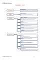
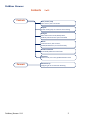
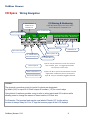
ProMtrac Browser
Browser Manual
ProMinent® ProMtrac
Cooling Tower
Water Treatment Controller
ProMtrac_Browser_Manual.docx (5/23/13): – pn.
Please completely read through these operating instructions first! Do not discard! The warranty shall be invalidated by damage
caused by operating errors!
ProMinent Fluid Controls, Inc. (USA) 136 Industry Drive, Pittsburgh, PA 15275
ProMtrac_Browser 5/13
1
ProMtrac Browser
Contents
I/O Space
1 of 2
Wiring Navigation
Wiring locations for sensors, meters, pumps & solenoids
Login
Browser Navigation
Pull downs for System, Sensors & Controls
System
Configure - Diagnostic
Site & System names, metric units, keypad password,
thermal flowswitch, Alarm on STOPs, Erase Log ….
Ethernet
Modify IP & Netmask
View Icons
Move & Enable real time view Icons
Passwords
View access level, modify password & userid
Time & Date
Modify the time & date used for feed events
Sensors
Calibrate
Enter new Value, Factory reset
Configure
Modify Name, Set meter scaling & Type
Alarms
High & Low alarms, Enable/Disable Alarms,
Delay on Alarm, Link to Alarm Relay
Diagnostic
Type, Measured range, default values, raw value
4-20mA Outputs
Controlling sensor select, 4 & 20mA levels, Auto-Manual
ProMtrac_Browser 5/13
2
ProMtrac Browser
Contents
Controls
2 of 2
Auto / Prime / Stop
Select control, test or force OFF
Setpoint
View & modify pump or solenoid control setting
Configure
Select feed-control mode, Modify Name,
Prebleed, lockout & event cycle for biocides
Alarms
Feed limit alarms, OFF on alarm,
Enable/Disable Alarms, Link to Alarm Relay
Biocide Feed Events
View-Modify-Add timed event feeds
Diagnostic
Current state, time owed, prebleed-lockout status
Connect
ProMtrac_Browser 5/13
Ethernet Set-up
Configuring for PC-to-controller browsing
3
ProMtrac Browser
I/O Space Wiring Navigation
I/O Naming & Numbering
Low Tank Level
OR Mechanical
Flowswitch ‘J’
Inputs & 4-20mA Outputs are letters A to K
Control Relays are numbered 1 to 5
Tower Conductivity ‘A’
Make-up Conductivity ‘B’
Flow
Cond:Mkp
R B G pH IN
ORP
Cond:Twr
R B G
IO1
Alarm Relay4 Relay3 Relay2 Solenoid AC Power
NC NO LF Line
5A 5B 4A 4B 3A 3B 2A 2B
Water Meters
+12 MU BD
IO2
A&B
Ethernet
Relays ‘2’ to ‘5’
IN
Bleed water meter ‘I’
pH or ORP Input ‘C’
1st 4-20mA Output
OR 4-20mA Input ‘D’
Manual Input ‘G’
Water Temperature ‘F’
Thermal Flowswitch ‘K’
Bleed Relay ‘1’
Make-up meter ‘H’
2nd 4-20mA Out ‘E’
Input ‘G’ may be used for the result of a chemical
test, hardness, ppm... it’s logged and alarmed
like any other sensor value
Inputs ‘F’ & ‘K’ are part of the data stream from the
digital tower conductivity sensor connected to
input ‘A’. They are individually logged & alarmed.
Sidebar:
The physical connection points for inputs & outputs are designated
by letters (A-K) for inputs & 4-20mA outputs & numbers (1-5) for control relays
Using letters & numbers provides a way to refer to wiring points and I/O locations while
allowing users to change the names of these location to fit their site.
For Example: The bromine feed may be user labeled ‘Feeder 123’ but the wiring
location is always Relay No.3 & a ‘3’ tags the browser pages & the LCD displays
ProMtrac_Browser 5/13
4
ProMtrac Browser
Login Browser Navigation 1 of 3
On-Site using a Notebook PC to a ProMtrac not on the Site LAN
A. You’ll need an Ethernet patch cable & a crossover adapter available
from office supply & electronics stores; Example: Office Depot #942378,.
B. You’ll need to set up a new connection in your notebook or PC.
Refer to Connect @ end of manual
Open the controller enclosure door, remove the lower access panel and jack into the controller
Ethernet jack located @ the bottom center of the controller circuit board.
Start Internet Explorer or Mozilla’s Firefox.
Notebook PC & Over the Site LAN
Key the controller IP address into the PC’s browser address.
You can find the controller’s IP address using the controller keypad (default = 10.10.6.106).
Refer to Connect @ end of manual.
ProMtrac_Browser 5/13
5
ProMtrac Browser
Login Browser Navigation 2 of 3
IN
Real time update of
sensors and controls
every 2 seconds
Pull down ‘Select User’
& select user ID, enter
Password & SUBMIT
Login to operate, change
setpoints, re-configure,
calibrate, clear alarms….
The right side of the page
is the user workspace &
the left side is the view.
The contents of the right
side change with each
selected link.
Select this link to view
the Inhibitor Pump
operate menus
Note: Views are optimized for limited resolution displays,
notebook & netbook PCs at 1024 x 768 pixels.
Default Passwords:
The factory default userids & passwords are:
Operator1 = 1 Operator2 = 2 Operator3 = 3 Operator4 = 4.
Configure5 = 5 Configure6 = 6 Configure7 = 7 Administrator = AAAA
There are 3 password levels, Operator, Configure and Administrator.
The User IDs are used in the controller’s keypress log.
WARNING: 5 incorrect passwords, blocks logon until 7:00AM or until a power OFF/ON.
ProMtrac_Browser 5/13
6
ProMtrac Browser
Login Browser Navigation 2 of 3
The selector at the top, right side of the browser page navigates to both System & I/O pages.
Once logged in, pull down the System
selector to access ProMtrac
configuration pages
Page load occurs on selection.
In this example, the Ethernet
setup page would load
Click on the Oxidant Pump link on the
left side of the view & the right side
loads the Diagnostic
Pull down the selector for
Oxidant Pump pages
Page load occurs on
selection.
Click on the Conductivity link on the
left side of the view & the right side
loads the Diagnostic
Pull down the selector for
Conductivity pages
Page load occurs on
selection.
ProMtrac_Browser 5/13
7
ProMtrac Browser
System Configure - Diagnostic
Yes sets units to ‘C’
for temperature & ‘L’
for meter volumes
Requires ‘admin’
login to modify.
All users may view
Keypad & Browser
passwords identical
Selecting Yes will default
the optional pH-ORP card
to ORP & Relay #3 to ORP
control.
Select No & pH-ORP card
measures pH & Relay #3
is an acid or caustic
pump control.
Select Yes if conductivity sensor installed on
make-up. Control options will include cycles.
Selecting Yes uses the thermal flowswitch
in the tower conductivity sensor &
enables input ‘K’
Selecting No uses a mechanical
flowswitch connected to input ‘J’ &
disbles input ‘K’
Selecting Yes causes an
alarm any time a user
selects STOP turning OFF
a pump or solenoid &
leaving it OFF.
Selecting Yes is the same as
cycling the power OFF/ON
Selecting Yes erases all logged
sensor, run time & status records.
Selecting Yes returns all
controls, sensor & meters to
facorty defualts. Resets the
names of all I/Os
Last digits of Serial# used
to identify both log &
configuration files
Current, loaded configuration file
Sequential
Firmware
version.
1
Build date or
last time ‘admin’
user reset
5 minute logging
interval total records.
0 to 18,000, 62.5 days
ProMtrac_Browser 5/13
# of times the controller has
restarted on electrical or
firmware fault. Should be
very low#
Helps with remote
connection support &
indicates user action to
block access
Voltage after +12 water
meter thermal fuse. Below
11V indicates external
wiring problem
8
ProMtrac Browser
System Ethernet
The default IP address is
10.10.6.106
Most sites & direct connects will
use this netmask
Defaults to 10.10.6.1
System View Icons
Any icon in the view can be
moved to the location of any
other icon.
Use this tool to make the view
reflect your system layout
Disabled inputs are removed from the view & LCD.
Enabled inputs automatically appear in the view &
the LCD display
ProMtrac_Browser 5/13
9
ProMtrac Browser
System Passwords
The ‘admin’ level user can
change their password
but not their userid
Operate Level users can
calibrate & change
setpoints.
Configure Level users can
change control & feed
methods
The ‘admin’ level user can
change all other users
Access Level
This user has Configure
level controller access
Each user can change
their default User ID
Up to 8 letters & numbers
may be used as a Password
NOTE: Keypad users can only enter numbers &
caps. Short passwords work best for these users
System Time & Date
Time & date used for
biocide feed events & to
stamp data log, alarms &
keypress record.
Set in Plug&Feed configuration
file & used at time of
manufacture to set time
correctly for your time zone
ProMtrac_Browser 5/13
10
ProMtrac Browser
Sensors Calibrate
Use a grab sample from the
sensor entry header to calibrate
Sensor scaling or filming may
cause an error message on
calibration. A very low
conductivity on Factory Reset
indicates a fouled sensor
The result of a manual chemical test may be
logged & alarmed by the ProMtrac.
Select Calibrate on input ‘G’ to log a test result
Input ‘G’ may be disabled @ Configure,
removing it from the browser view
& the LCD display
Sensors Configure
1 of 2
Description can be up to 14
characters. HTML characters,
<>&%.. are blocked
Volume/contact becomes
‘K’ Factor; pulses/gallon or
pulses/liter for Turbine meter
selected
Meter Type selects either contact head or
insertion paddlewheel-turbine. Higher speed
turbines are not debounced. Contact head
meters are debounced to block false counts.
ProMtrac_Browser 5/13
11
ProMtrac Browser
Sensors Configure
2 of 2
The bleed water meter may
configured as either a
Contact Meter or Turbine Meter
Input ‘I’ may be disabled
removing it from the browser view
& the LCD display
Sensors Alarms
1 of 2
Disabling alarms may hide
operational problems
High Alarm typically set @
chemistry limit for cycles
limited towers
Low Alarm typically used to
catch open bleed solenoids
& tower overflows
or sump leaks.
Delay on Alarm used to
block nuisance alarms on
transient operating states
ProMtrac_Browser 5/13
12
ProMtrac Browser
Sensors Alarms
2 of 2
High Alarm is the daily volume
Low Alarm is checked at midnight.
Set to zero for towers OFF over
weekends to prevent alarming
Sensors Diagnostic 1 of 2
Inhibitor ppm sensors
connect to the isolated 420mA input card @ input ‘D’
Gain & Offset are used to
convert the mV measured on
the current loop input to ppm
In this example 674.6 mV x
1.25 -250 = 593 ppm
( mV x Gain – Offset = ppm)
Measured Level is the mV
across the 50 ohm 4-20mA
loop termination.
( 0.6746V / 50 = 13.5mA )
ProMtrac_Browser 5/13
13
ProMtrac Browser
Sensors Diagnostic 2 of 2
Users may change the
make-up meter name but
it’s always connected to
input ‘H’
Period starts from most
recent Power ON
& ends @ midnight
The meter connected to input ‘H’
is a contact head type, scaled @
180 Gallons / contact closure
Sensors 4-20mA Outputs
Select Yes to switch to Manual,
user control of the loop current
If the tower conductivity = 1000uS
Then the 4-20mA loop current
would be: 8mA =
4mA + 16mA x (1000 / 4000 )
Pull down to select the sensor
which controls the 4-20mA output
In this example, the 4-20mA output
is controlled by the tower
conductivity connected to input ‘A’
& spanned 0-4000uS = 4-20mA
4-20mA Outputs may be set to Manual where
the loop current is fixed by the user.
Select Yes to return to sensor control of the loop
In this example, the 4-20mA @ ‘E’ is set
to 60% for a loop current of
0.6 x 16mA +4mA = 13.6mA
ProMtrac_Browser 5/13
14
ProMtrac Browser
Controls Auto / Prime / Stop
Auto ProMtrac is controlling
the pump, valve or solenoid
PRIME pump, valve or solenoid turns ON for a
user set time, if flowswitch is ON.
Returns to Auto @ end of PRIME time
STOP pump, valve or solenoid turns OFF & stays
OFF until the user selects PRIME or Auto.
Time Owed is the owed pump ON time caused by
measured volume on Control by: I, the bleed water.
In this example 2.7 minutes is caused
by measuring 1620 gallons
( 1620G / 100G x 10s = 162 sec or 2.7 minutes)
Controls Setpoint 1 of 2
The Configure page displays the current
pump control method & setpoints
Every 100 gallons of make-up
The inhibitor pump connected to relay 2,
turns ON for 10 seconds
Bleed delays Feed used on meter controls
where towers not bleed limited
(Bleed not always ON when high thermal load)
ProMtrac_Browser 5/13
15
ProMtrac Browser
Controls Setpoint 2 of 2
Note: If we re-purposed Relay 5 as
bleed control on conductivity & wired
it in parallel to the solenoid, we would
have a high conductivity fail-safe
In this example, we’re using the ratio
of Tower make-up to bleed volume.
Every 100 gallons of make-up, the
Bleed Solenoid turns ON for 25 gallons;
4 cycles of concentration
Diagnostic shows Control by: the
meters connected to inputs ‘H’ & ‘I’
When the make-up meter measures
12340 gallons the bleed will turn ON
for 25 Gallons
ProMtrac_Browser 5/13
16
ProMtrac Browser
Controls Configure 1 of 4
Make-up or Bleed meter provides reliable &
accurate feed controls.
Bleed & Feed and Bleed then Feed typically
used on smaller towers.
Percent Time used to slug on start-up or to bridge
maintenance or sensor problems.
Fluorescent offered if option card installed
Most towers control the Bleed using Conductivity.
Sites with constant make-up chemistry may the use the
ratio of volumes; Make-up/Bleed Meter, measured by
water meters for cycle control
If a make-up water conductvity sensor is installed, the
Tower/Make-up Ratio control option is available.
Make-up meter bleed control would typically be limited to
sites with constant make-up water chemistry
Percent Time used to slug on start-up or to bridge
maintenance or sensor problems.
ProMtrac_Browser 5/13
17
ProMtrac Browser
Controls Configure 2 of 4
Note: Select a bleed control method that works with the
tower water chemistry & holding time.
Ratio of conductivities may be inappropriate for a
tower with a long holding time & frequent make-up
water conductivity changes
In this example, we’re using the ratio
of Tower to Make-up conductivity to
control the cycles of concentration,
so both the the setpoint and the
deadband are in cycles.
Prebleed turns on the bleed before a timed feed event.
If the conductivity measures 500uS before 35.0 minutes
elapses, Prebleed ends & the feed event starts
Lockout prevents the bleed from turning ON to allow kill
times. Typically more common with non-oxidixizing biocides.
Lockout time starts at the beginning of the feed event time.
Event ORP controls Oxidant Pump during timed events.
Deadband is applied to TurnON to set TurnOFF.
Default Deadband varies with sensor type
ProMtrac_Browser 5/13
18
ProMtrac Browser
Controls Configure 3 of 4
Select Configure to repurpose
Alarm Relay:5 to
another inhibitor, bleed or
timed event control
In this example we’re re-purposed Relay 5
to be a 2nd inhibitor feed.
All of feed control options that are availble
on the Relay 2 inhibitor pump control are
also available on Relay 5
Relay 5 can be returned to being
an alarm relay by selecting Yes
ProMtrac_Browser 5/13
19
ProMtrac Browser
Controls Configure 4 of 4
If the ProMtrac is using the thermal
flowswitch built into the conductivity sensor,
input ‘J’ is available for a tank level switch
or a filter backwash monitor…
The ProMtrac measures ON when a
contact set is closed. If your dry
contact input is active in the open
state, then select Invert sense Yes
Controls Alarms 1 of 3
When any I/O alarms, both the I/O location
& the controller icon show Alarm
ProMtrac_Browser 5/13
20
ProMtrac Browser
Controls Alarms 2 of 3
Disable turns OFF the
inhibitor pump feed limit
Day Timeout resets @ midnight so you can set a maximum
amount of inhibitor pumped in a day
OFF on Alarm typically set to Yes for Inhibitor, Acid &
Oxidant pumps & No for Bleed Solenoids
Feed limit alarms are typically disabled for
non-oxidizing biocides & enabled for
oxidizing biocides.
ProMtrac_Browser 5/13
21
ProMtrac Browser
Controls Alarms 3 of 3
Use the Bleed ON Timeout to alert
you to a long bleed cycle which may
indicate a blocked or faulted bleed
valve
OFF on Alarm typically set to No for
bleeds, so bleed to stays ON when alarmed
Alarm Relay displays if Relay 5 is used
as an alarm relay.
Yes turns ON the alarm relay when the
bleed ON time exceeds ON Timeout
If an control or sensor alarms,
the Alarms page displays the alarm
type & the alarm time-date stamp
ProMtrac_Browser 5/13
22
ProMtrac Browser
Controls Biocide Feed Events
Pull down selector to see all timed feed events
Modify these fields to Edit or Add an event
If Adding an event, select Frequency.
Frequency options vary with the current
Event Cycle: 1,7 or 28 days
Diagnostic on biocide controls shows both
the #of events & the event cycle.
Displays the Prebleed state
when an feed event is
running
ProMtrac_Browser 5/13
23
ProMtrac Browser
Controls Diagnostic
Use Bleed Diagnostic for ON today
& actuation times.
Extended ON time may indicate a
bleed limited tower, or a change in
make-up water chemistry.
Long actuation time may indicate a
too large deadband
ProMtrac_Browser 5/13
24
ProMtrac Browser
Connect Ethernet Set-up 1 of 3, Windows
Windows operating systems have a simple way to find the Ethernet setup parameters:
You can use either the Keypad-LCD interface or the browser to setup the controller’s IP Address,
Netmask, Gateway & Primary DNS.
ProMtrac_Browser 5/13
25
ProMtrac Browser
Connect Ethernet Set-up 2 of 3, Windows 7
ProMtrac_Browser 5/13
26
ProMtrac Browser
Connect Ethernet Set-up 3 of 3, Windows 7
Select TCP/IPv4 then select
Use the follwing...
Note the present IP Address and gateway,
server settings before you modify.
You’ll need to restore them after browsing the
controller if you use the local Ethenet jack to
connect to other devices or services
Edit the IP address,
10.10.6.200 in this example
& OK
We’ve put our notebook PC
on the same LAN as the
ProMtrac. Now we can
connect using an Ethernet
cross-over cable
ProMtrac_Browser 5/13
27