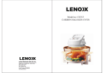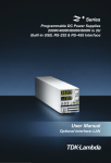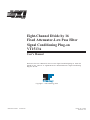
1
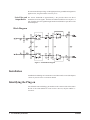
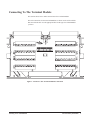
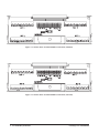
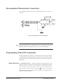
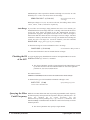
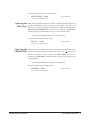
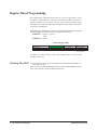
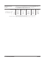
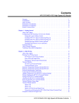
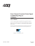
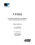
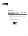
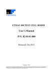
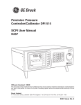
bus
Eight-Channel Divide by 16
Fixed Attenuator-Low Pass Filter
Signal Conditioning Plug-on
VT1513A
User’s Manual
Enclosed is the User’s Manual for the VT1513A Signal Conditioning Plug-on. Insert this
manual in your VT1413C or Agilent/HP E1313 manual behind the “Signal Conditioning
Plug-ons” divider.
Copyright © VXI Technology, 2003
Manual Part Number:
82-0087-000
Printed: July 9, 20032
Printed in U.S.A.
VT1513A
Eight-Channel Divide by 16 Attenuator
Signal Conditioning Plug-on
Introduction
The VT1513A is a Signal Conditioning Plug-on that provides eight divide by 16
attenuators and fixed low-pass filters with a 3 dB cutoff frequency of 7 Hz. Also
provided is input over-voltage protection.
The VT1513A allows maximum input voltage of 60 VDC between High and Low,
or from High or Low to Chassis.
About this Manual
This manual shows you how to control the Signal Conditioning Plug-on (SCP)
using SCPI commands as well as Register-Based commands, and explains the
capabilities of this SCP. Finally, it covers specifications for this SCP. The contents
of this manual are:
·
·
·
·
·
·
·
Description . . . . . . . . . . . . . . . . . . . . . . . . . . . . . . . . . . . . . . . . . . . . . . . .
Installation . . . . . . . . . . . . . . . . . . . . . . . . . . . . . . . . . . . . . . . . . . . . . . . .
Identifying the Plug-on . . . . . . . . . . . . . . . . . . . . . . . . . . . . . . . . . . . . . . .
Connecting To The Terminal Module . . . . . . . . . . . . . . . . . . . . . . . . . . . .
Programming With SCPI Commands . . . . . . . . . . . . . . . . . . . . . . . . . . . .
Programming With Register Commands . . . . . . . . . . . . . . . . . . . . . . . . .
Specifications . . . . . . . . . . . . . . . . . . . . . . . . . . . . . . . . . . . . . . . . . . . . . .
1
2
2
3
5
8
9
Description
Attenuator The VT1513A is a balanced high impedance input attenuator that provides both
1
differential mode and common mode gain of ( ). The input resistance is 1 MOhm
16
to chassis from either the high or low input.
The resistor network used for the attenuator, provides accurate gains and moderate
common mode rejection. The gains will be within 0.1% of each other and the
common mode rejection will be approximately 60 dB. The input will not be a true
differential input, in that the gain on the low side cannot be calibrated. Therefore
the gain will be specified from high to low and the low input should be connected to
Introduction
VT1513A Divide by 16 Attenuator 1
the common mode input voltage. If the high input where grounded and a signal was
applied to low, the gain could be in error by 0.1%.
Noise Filter and The narrow bandwidth of approximately 7 Hz provides about 27.8 dB of
Output Buffer attenuation for 60 Hz signals. The filters are balanced and have two real poles. A
pair of buffers drive the signal through another broad band low-pass filter to the
A/D multiplexer.
Block Diagram
Figure 1 Partial Block Diagram
Installation
Installation for this Plug-on is common to several others and is covered in Chapters
1 and 2 of your VT1413C or VT1415A manual.
Identifying the Plug-on
You’ll find the VXI Technology part number on the connector side of the SCP to
the left of the serial number bar code. For the VT1513A, the part number is :
VT1513A.
2 VT1513A Divide by 16 Attenuator
Installation
Connecting To The Terminal Module
This section shows how to make connections to the Terminal Module.
The SCP connections for the Terminal Modules are shown on the stick-on labels
that came with the SCP. Use the appropriate label for the type of Terminal Module
you have.
Figure 2 VT1513A C-Size Terminal Module Connections
Connecting To The Terminal Module
VT1513A Divide by 16 Attenuator 3
Figure 3 VT1513A B-size Terminal Module Connections (Ch 00-31)
Figure 4 VT1513A B-size Terminal Module Connections (Ch 32-63)
4 VT1513A Divide by 16 Attenuator
Connecting To The Terminal Module
Recommended Measurement Connections
The following illustration shows the recommended method of wiring to the
VT1513A.
Figure 5 Wiring to the VT1513A Attenuator
Note All guard connections for a particular SCP tie to a common point, therefore
different common mode voltages should not be tied to this shared guard.
Programming With SCPI Commands
The SCPI commands shown here are covered in Chapters 3 and 5 of your VT1413C
or Agilent/HP E1313 manual and Chapters 3 and 6 of your VT1415A manual. This
section will relate those commands to the parameter values which are specific to
this Plug-on.
Range Selection
The [SENSe:]Function:... commands include the range parameter. This
parameter selects the A/D range for the measurement. Set this parameter based on
the maximum input voltage you expect, divided by 16 (the attenuation factor).
1
While you have to keep in mind the channel gain ( ) when you set the range, the
16
DSP knows the gain and your range selection, and returns the actual input value,
not the divided value. Example:
Recommended Measurement Connections
VT1513A Divide by 16 Attenuator 5
Maximum input value expected for channels 32 through 35 is 48 volts. 48 volts
divided by 16 is 3 volts. You can use the 4 volt A/D range.
SENS:FUNC:VOLT 4,(@132:135)
meas volts on chs 32-35,
4 V range
With input voltages of 15, 22, -40, and 55 volts DC, the reading values will be
1.5E+1, 2.2E+1, -4.0E+1, and 5.5E+1 respectively.
Auto-Range If you wish to use auto-range (range parameter not sent or set to AUTO), you
should limit the lowest A/D range used to the 1 volt range. The reason for this can be
seen in the noise figures presented in the “DC Measurement Accuracy”
specifications on page 10. The signal-to-noise ratio of the 1 and 4 volt ranges is
much better than the 0.0625 and 0.25 volt ranges. The lower ranges’ increased
resolution is offset by increased noise. To keep your module from selecting the
0.0625 and 0.25 volt ranges for VT1513A channels, send the command
DIAG:FLOOR <range_floor>,(@<ch_list>). Example:
To limit lowest range on VT1513A channels to the 1 volt range
DIAG:FLOOR 1,(@132:140)
all 8 channels in SCP position 4
The same noise limitation is true for manual selection of ranges.
Checking the ID
of the SCP
To verify the SCP type(s) installed on the VT1413C and Agilent/HP E1313 use the
SYSTem:CTYPe? (@<channel>) command.
· The channel parameter specifies a single channel in the channel range covered
by the SCP of interest. The first channel number for each of the eight SCP
positions are; 0,8,16,24,32,40,48 and 56.
The returned value is:
HEWLETT-PACKARD,E1513A 8-Channel Fixed Attenuator-Filter SCP,0,0
To determine the type of SCP installed on channels 0 through 7 send
SYST:CTYP? (@100)
query SCP type @ ch 0
execute enter statement here
Querying the Filter
Cutoff Frequency
While the Low Pass Filter SCP does not provide programmable cutoff frequency
the filter frequency can be queried. The response to this query will always be 7. To
q u e r y a n y ch a n n e l f o r its c u to f f f r e q u e n c y u s e th e
INPut:FILTer[:LPASs]:FREQuency? (@<channel>) command. The
INP:FILT:FREQ? command returns the numeric cutoff value currently set for the
channel specified.
· The channel parameter must specify a single channel.
6 VT1513A Divide by 16 Attenuator
Programming With SCPI Commands
To query the cutoff frequency of channel 6 send
INP:FILT:FREQ? (@106)
query channel 6
execute enter statement here
Querying the
Filter State
While the Low Pass Filter SCP does not allow controlling whether the filters are
enabled or disabled, this state can be queried. The response to this query will
always be 1. To query any channel to determine if it is enabled or disabled use the
INPut:FILTer[:LPASs][:STATe]? (@<channel>) command. The INP:FILT?
command returns a 0 if the channel is OFF or a 1 if the channel is ON.
· The channel parameter must specify a single channel.
To query the filter state of channel 2 send
INP:FILT? (@102)
query channel 2
execute enter statement here
Querying the
Channel Gain
While the Low Pass Filter SCP does not provide amplifiers, the channel gain can be
1
queried. The response to this query will always be 0.0625 (gain = ). To query any
16
channel to determine its gain setting use the INPut:GAIN? (@<channel>)
command. The INP:GAIN? command returns the current gain value for the
specified channel.
· The channel parameter must specify a single channel.
To query the gain setting of channel 8 send
INP:GAIN? (@108)
query channel 8
execute enter statement here
Programming With SCPI Commands
VT1513A Divide by 16 Attenuator 7
Register Based Programming
The register-based commands shown here are covered in Appendix D of the
VT1413C or Agilent/HP E1313 manual. You should read that section first to
become familiar with accessing registers and executing Register-Based
Commands. This section will relate those commands to the parameter values which
are specific to this Plug-on.
When Register Programming an SCP most communication is through the Signal
Conditioning Bus. For that you will use the Register Commands:
SCBWRITE <regaddr> <regvalue>
and
SCBREAD? <regaddr>
VT1513A Register Map
Read (returned value)
SCP ID (707016)
Write( <regvalue>)
SCP Register
Whole SCP Reg 0
<regaddr> Value
00ppp0000002
ppp=Plug-on
ccc=SCP channel
In addition you will access bits in the Card Control register to control Open
Transducer Detection.
Checking ID of SCP
8 VT1513A Divide by 16 Attenuator
To query an SCP for its ID value, write the following value to Parameter Register 1:
( SCP number ) ´ 4016
Then write the opcode for SCBREAD? (080016) to the Command Register. The ID
value will be written to the Query Response Register.
Register Based Programming
Specifications
These specifications for the VT1513A reflect the combined performance of the
VT1413C or Agilent/HP E1313 and the VT1513A Signal Conditioning Plug-on.
These specifications are not to be added to those presented in the VT1413C User’s
Manual.
General Specifications
±1 V to ± 60 VDC Full Scale
Measurement ranges
Operating: ±60 VDC
Maximum input voltage
±42 V peak
(Normal mode plus common mode)
Maximum common mode
voltage
Operating: ±60 VDC ±42 V Peak
@ 7 Hz -3dB, @ 50 Hz > -24@ 60 Hz > -27 dB
Normal mode rejection
0 - 60 Hz - 60 dB
Common mode rejection
1 MOhm ±1% (each differential input to ground)
Input impedance
(Maximum tare offset depends on A/D range and SCP gain)
Maximum tare cal offset
Specifications
A/D range
±V F.Scale
16
4
1
0.25
0.0625
Max Offset
49.95
13.13
3.689
1.212
0.606
VT1513A Divide by 16 Attenuator 9
(90 days) 23°C ±1°C (with *CAL? done after 1 hr warm up and CAL:ZERO? within 5
min.). If autoranging is ON, add ±0.02% FS to accuracy specifications.
For Agilent/HP E1313, multiply Noise Spec. by 1.4.
Measurement accuracy
DC Volts
A/D Range (±V FS)
These ranges are Ä 0.0625
not recommended Ä 0.25
1
4
(1 V)
(4 V)
(16 V)
(60 V)
Linearity
% of reading
Common Mode
Error % of Vcm
Offset Error
Noise
3 sigma
Noise*
3 sigma
0.02%
0.02%
0.02%
0.02%
0.1%
0.1%
0.1%
0.1%
100 µV
175 µV
500 µV
1.95 mV
700 µV
860 µV
1.8 mV
7.0 mV
280 µV
430 µV
1.4 mV
5.8 mV
* [SENSe:]FILTer[:LPASs][:STATe] ON (max scan rate - 100 readings/s/channel)
Temperature Coefficients: Gain - 0.001/°C. Relative to temp at last *CAL?
Offset - (0 - 40°C) 0.14 µV/°C, (40 - 55°C) 0.8 µV+0.38 µV/°C Relative to 23°C.
10 VT1513A Divide by 16 Attenuator
Specifications