1
SERIAL PORTS
BASIC
SECTION 4
system supports 8 bit address (0-255). Future operating
systems may support 16 bit address. Default modbus
address is 11. This is changed through register 4811.
COM0 SERIAL PORT
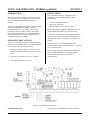
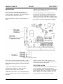
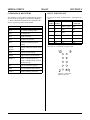
This port at J1 uses a VTC-9F serial cable to connect
external serial devices to the port. The cable consists of
a 10 pin IDC connector wired one-to-one to a DB-9
connector. Line 10 is simply cut off. The pin out is
designed so it plugs directly into the 9 pin serial port
connector on a PC.
ASCII mode operates in a similar manner as COM 0
when a Basic program is running. Use PRINT #3 and
GET(3) to send and receive data.
The CX-10 can operate in modbus master mode. See
registers 4781-4783 for more information.
Baud rate is fixed at 19,200, 8 data, no parity, 1 stop bit.
COM0 is used for programming. During run time it may
be used as a general purpose serial port. When used for
programming or with the INPUT statement, it accepts
ASCII character values from 0 to 127. When used with
the GET function, it will return ASCII values from 0 to
255.
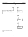
Modbus ID’s
A modbus master device may be connected to a larger
network through 450 Mhz radios. The master, in this
case, will have its own modbus ID. However, slaves
connected to this master can have the same ID’s as other
modbus masters.
COM0 does not have handshaking lines.
It is a good idea to make each CX-10 device a unique
when using the RF modem. The RF modem can, under
ideal conditions, send and receive up to 40 miles. If
there will be other similar RF modems it is best to make
each CX-10 and other modbus units have their own ID in
case another master can be received the slave.
COM3 SERIAL PORT
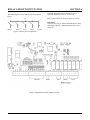
COM3 is an RS-232 , radio modem, and/or RS-485 port.
A VTC-9F serial cable, described above, is used for RS232 level communications. RS-232 is from header J2.
RS-485 is from P4 and is designated as “485A” and
“485B”
Networking the CX-10
The CX-10 may be part of a modbus network with other
CX-10's or modbus devices, under the right conditions.
There are two conditions where this is possible:
Additionally, a 900 Mhz radio modem may be plugged
into the board.
All three ports may be used more or less at the same
time. This is both convenient and a danger. The
convenience is the radio modem may be used to talk to
both the CX-10 and other devices over RS-232 or RS485. The danger is when two devices talk at the same
time. Data will collide, become garbled and unusable. It
is important, therefore, that any devices connected to the
CX-10 be slaves and not initiate any transmission unless
requested.
1. Master modbus communications take place over
RS-485.
2. Master modbus communication take place using
the RF modem. Under this condition, the RS-485
port may be used to connect to other modbus
devices.
RS-232 may be used to communicate to a modbus
master. However, due the nature of RS-232, only one
device may be connected.
Protocol Modes
COM 3 can operate as a modbus protocol port or ASCII
port. By default, COM 3 operates as a modbus port.
Operating mode is changed in register 4810. Writing a 1
sets this port to operate in modbus while a 0 sets it to
operate in ASCII.
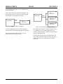
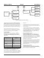
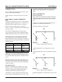
CX-10 interfacing in a system
The CX-10 is connected to a system in one of several
ways.
Two broad considerations are: Is the CX-10 going to be
wired to a master or use an RF modem? Will there be
other modbus slaves in the system?
ASCII mode is useful if the CX-10 is not running
modbus and a serial keypad & display are attached.
The drawings below illustrate some of these possible
configurations.
If you will not be running a Basic program, default
operation should be left as modbus.
Be sure to read the section “RS-485 OPERATING
INFORMATION” below. RS-485 can operate as a 2- or
4-wire system. The CX-10 is a 2 wire system. Make
While operating in modbus protocol mode, function
arguments 3 and 16 are recognized. Current operating
Page 4-2