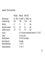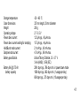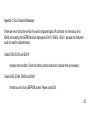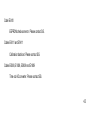
1
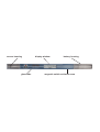
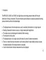
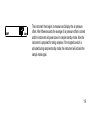
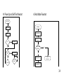
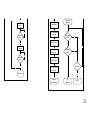
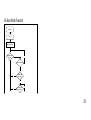
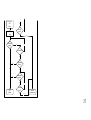
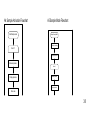
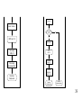
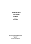
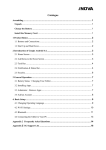
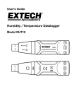
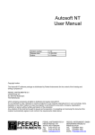
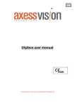
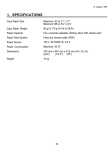
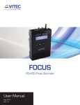
RPM 2000 X, 6000 X AND 10000 X USER MANUAL
SiS Sensoren Instrumente Systeme GmbH
Mühlenkoppel 12
D-24222 Schwentinental, Germany
sensor housing
glass tube
display window
battery housing
magnetic switch activation area
CONTENTS
1. Introduction....................................................................................................................................................6
1.1 General Description.................................................................................................................................8
1.2 Packing List .............................................................................................................................................9
2. Putting Into Operation .................................................................................................................................10
2.1 Insertion of Battery ................................................................................................................................10
2.2. Self Test ...............................................................................................................................................11
2.3 Enhanced Self Test and Instrument Data..............................................................................................12
3. Operational Instructions and Operation Modes ...........................................................................................15
3.1 General Operational Instructions ...........................................................................................................15
3.2 Hold Mode .............................................................................................................................................16
3.3 Sample Mode ........................................................................................................................................18
3.3.1 Activation of the Sample Mode (Preparing for Sampling) ...............................................................18
3
3.3.2 Sampling Values.............................................................................................................................20
3.4 Burst Mode ............................................................................................................................................22
4. Low Battery Condition .................................................................................................................................24
5. Measuring Range ........................................................................................................................................25
6. Cleaning and Handling ................................................................................................................................26
7. Transport and Storage ................................................................................................................................27
8. Service and Maintenance ............................................................................................................................28
8.1 Replacement of Wearing Parts .............................................................................................................30
8.2 Replacement of Battery Contact............................................................................................................31
8.3 Replacement of Battery Contact Spring ................................................................................................31
9. Trouble Shooting .........................................................................................................................................32
9.1 Ingress of Water Into the Battery Housing.............................................................................................32
9.2 Ingress of Sea Water Into the Main Housing .........................................................................................33
10. Calibration .................................................................................................................................................33
4
Appendix A: Operational Modes Flowcharts....................................................................................................34
Appendix B: Technical Specification ...............................................................................................................40
Appendix C: Error Codes and Messages ........................................................................................................42
Appendix D: Spare Parts and Batteries...........................................................................................................46
Appendix E: Warranty and Support.................................................................................................................49
5
1. Introduction
The RPM 2000 X, 6000 X and 10000 X are digital deep sea reversing pressure meters with the outer
dimensions of mercury instruments. They have the same positive features as classical unprotected reversing
pressure meters but without the disadvantages:
•
•
•
•
•
•
The displayed value is the real sample value, use of a secondary thermometer is no longer required.
Reading of values with maximum accuracy no longer needs optical magnification.
The sample value is protected against inadvertent further reversing.
The instrument is mercury free.
The displayed value is not a single value but the mean of a series of sixteen measurements.
There is no need to have two instruments in each reversing frame for value reliability analysis, because
the standard deviation of the measured series is evaluated.
• In burst mode all sixteen individual measurements can be displayed.
6
• Automatic offset nullbalance by initialising the sample mode.
7
1.1 General Description
The RPM 2000 X, 6000 X and 10000 X are reversing pressure meters with depth ranges of up to 2000, 6000
and 10000 meters respectively. The housing is made of a glass tube, closed at the ends by titanium
stoppers. One stopper contains the pressure sensor and the other is the battery compartment.
The instrument is operated by a magnetic programming switch for stepping through the operational modes
‘HOLD’, ‘SAMP’ and ‘BURST’.
A battery test indicates the need for battery replacement.
8
1.2 Packing List
1
1
1
1
1
1
RPM 2000 X, 6000 X or 10000 X pressure meter
Magnetic bar
User manual
Factory calibration certificate
Battery
Spare parts kit with
2 O-rings
1 locking spring
9
2. Putting Into Operation
2.1 Insertion of Battery
battery
housing
battery
+ terminal
turn clockwise
and
- pull to open
- push to close
The battery is placed in a separate compartment outside the main
pressure housing at the opposite end to the sensor head. The
main housing does not need to be opened to replace the battery.
To open the battery compartment, turn it clockwise whilst pulling it
apart from the main housing. Put battery into its housing with
negative (-) terminal down towards the contact spring. Refit
battery compartment to main housing turning it clockwise as it is
pushed home. The housing is sealed by two O-rings.
10
2.2. Self Test
dbar
After the insertion of a battery, the instrument will perform a self test.
This is indicated by displaying ‘CHECk’ for a period of about five
seconds. If an error occurred, you will see the message ‘Exxxx’ on the
display where ‘xxxx’ is an error code (see appendix C, Error Codes and
Messages).
11
2.3 Enhanced Self Test and Instrument Data
The enhanced self test mode can be activated by operating the
magnetic switch during the five second start up delay whilst the display
shows ‘CHECk’.
HOLD BUR
CONT
SAMPBAT
o
C
dev
dbar
At first all elements of the display are activated.
12
Another activation of the magnetic switch will display the serial number
of the instrument.
dbar
The serial number is 2013.
Another activation of the magnetic switch will display the calibration
month and year.
dbar
Last calibration date is March 1997.
13
Exit enhanced self test by activating the magnetic switch once more. The instrument will switch to the hold
mode. Please note the instrument will not automatically switch to power down mode during enhanced self
test. Always exit enhanced self test to ensure longer battery life.
14
3. Operational Instructions and Operation Modes
3.1 General Operational Instructions
The instrument has two operational elements:
• A magnetic switch behind the dotted area. The switch is activated by passing over that area with the
magnetic bar provided. Please note, there must be a delay time of at least one second between two
consecutive activations of the magnetic switch.
• An internal mercury free tilt switch that is activated by reversing the instrument (sensor head is pointing
upwards) and de-activated when the sensor head is pointing downwards.
15
3.2 Hold Mode
Before activating the instrument with the magnetic switch, ensure that the sensor is pointing upwards to avoid
clearing the sample values by switching inadvertently to the sample mode. The source of the displayed value
(from sample mode) is indicated by ‘SAMP’.
HOLD
SAMP
dbar
In the hold mode the results from the last sampling are displayed. At
first the average of the sixteen sample values is displayed for five
seconds.
16
HOLD
SAMP
dev
dbar
Next the standard deviation, calculated from the sixteen values, is
displayed for two seconds. The standard deviation of the single
measurements is an indicator of the stability and accuracy of the
sample values. The standard deviation for the mean value is one
quarter of the indicated value.
Before power down, the instrument will display the average and deviation once again for five and two
seconds respectively and finally the average for five seconds.
17
3.3 Sample Mode
3.3.1 Activation of the Sample Mode (Preparing for Sampling)
To enter the sample mode, the magnetic switch must be activated when in the hold mode with the sensor
head pointing downwards. If the sensor head is pointing upwards, the instrument is locked to prevent
overwriting of the last sample result.
SAMP
dbar
Activation of the sample mode is indicated by the SAMP indicator in the
display. The digit fields in the display will be blank for a period of 1
second.
18
SAMP
dbar
The instrument then begins to measure and display the air pressure
offset. After fifteen seconds the average of air pressure offset is stored
and the instrument will power down in sample standby mode. Now the
instrument is prepared for taking samples. If the magnetic switch is
activated during sample standby mode, the instrument will activate the
sample mode again.
19
3.3.2 Sampling Values
SAMP
SAMP
dbar
dbar
Sampling will start when the instrument is reversed (sensor head is
pointing upwards). The instrument displays the ‘SAMP’ indicator with
blank digit fields for one second.
After three measurements for about 2.5 seconds to ensure that the
measuring values are stable, sixteen measurments are taken in fifteen
seconds before power down. The displayed values are corrected by the
air pressure value obtained during the preparing to sample sequence.
By this, means variations in air pressure will be balanced out and, more
importantly, any eventual offset drift of the sensor element will
automatically be null-balanced. The instrument must be in the reversed
state during the whole sample time. If the instrument is turned back to
20
the non reversing position during sampling for a period of one second, it
will immediately power down into sample standby mode.
21
3.4 Burst Mode
The burst mode will display all sixteen sample values, which are used to calculate the average and standard
deviation for the hold mode, and the (air pressure) offset from starting the sampling mode.
To activate the burst mode, the instrument must be in power down mode and activated by the magnetic
switch without removing the magnetic bar from the activation area. After five seconds in the hold mode, the
instrument will switch to the burst mode, which is indicated by ‘BUR’. The source of the burst values (from
sample mode) is indicated by ‘SAMP’.
BUR
SAMP
dbar
To display the next burst value, the magnetic switch must be activated.
If the magnetic bar is still over the activation area after two seconds, the
next burst value will be automatically displayed. This automatic mode
can be entered or left at any time during the burst mode. If there is no
22
activity from the magnetic switch for fifteen seconds, the instrument will
switch to the power down mode.
dbar
After the display of the sixteen burst values, the instrument will display
the offset value from starting the sampling mode. This offset includes
an eventual drift since the last calibration of the instrument. So it is not
only a correction of the varying air pressure, but also an indicator of the
drift of the instrument. Another activation of the magnetic switch will
return to the hold mode. It is not possible to switch back to burst mode
now. To enter the burst mode again, the instrument must be in power
down mode.
23
4. Low Battery Condition
HOLD
BAT
dbar
BAT
dbar
The blinking BAT indicator is displayed if the battery is nearly
discharged. The instrument is able to do about 10 or more measurings
after the first display of the BAT indicator.
If the battery is not able to power the instrument for measurings, it will
display the BAT indicator and the message 'LO'. The last results may
be still read out in Hold or Burst mode.
The battery test is only executed during sample mode or self test. In hold or burst mode the battery condition
from the last sample mode or self test is displayed.
24
5. Measuring Range
HOLD
dbar
The instruments are designed and calibrated for the specified pressure
ranges of 2000, 6000 or 10000 dbar. The 2000 and 6000 types are
able to measure and display pressures some dbar above the specified
range. The 10000 type can not display pressures above 9999.9 dbar. If
the pressure is too high, the instrument displays ‘OF’ to indicate
overpressure.
25
6. Cleaning and Handling
After using the instrument in salt water, it should be rinsed with fresh water. The sensor head especially,
should be cleaned through the pressure port slits of the sensor protective cap.
Although the instrument may be used at high pressure, it is sensitive to mechanical stress. So please handle
the instrument with care. Take special care not to subject the housing to any leverage when inserting it into
or removing it from, the reversing frame.
26
7. Transport and Storage
During transportation and storage the instrument should be in power down mode from hold mode or the
battery should be removed. If the battery is not removed, the magnetic bar should be placed away from the
activation area to avoid discharging the battery. Please note, the last sampling result is cleared when the
battery is removed.
The instrument should not be exposed to temperatures above 65 °C. Higher temperatures may damage the
display. Please comply also with the requirements for used batteries. Most Lithium batteries should not be
exposed to temperatures above 70 °C.
When storing the instrument at temperatures below 0 °C, ensure that the pressure sensor is dry to avoid frost
damage.
27
8. Service and Maintenance
NOTE: The replacement of the consummable parts, described below, should only be done by qualified
technical personnel. Inexpert handling can cause serious damage. Do not open the instrument
housing. There are no serviceable parts inside. Opening the housing will invalidate the
calibration and render the warranty void.
For a list of available spare parts and tools see appendix D.
28
O-ring
2x
locking
spring
protection
cap
battery
contact
battery
contact battery
spring housing
29
8.1 Replacement of Wearing Parts
Remove the locking spring and the O-rings with a small screw driver. Be very careful not to scratch the
grooves. Then clean the grooves with a dry, lint free cleaning cloth and check the grooves for marks. If there
are any, replacement of the complete instrument housing is necessary. Grease the O-rings lightly with silicon
paste. There should only be a thin film on the rings. Move the first O-ring over the insertion tool and place the
ring in the rear groove. Then insert the other O-ring into the next groove. Finally, push the locking spring into
the front groove.
30
8.2 Replacement of Battery Contact
Begin by removing the reverse battery protection cap using a small screw driver to lever it out. Then screw
the removal and insertion tool into the old battery contact and pull it out. Use the tool again to insert the new
contact then reassemble the protection cap.
8.3 Replacement of Battery Contact Spring
To remove the old spring, use small pliers to pull the spring out of the housing. Place the new spring with the
wide side first into the coned end of the outer part of the insertion tool. Use the inner part of the tool with the
coned end to press the spring into the outer part. Place the tool on a plane surface and press the spring
nearly down to the end of the tool. If the spring is placed straight inside, push the tool into the battery housing
and press the spring down until it snaps in.
31
9. Trouble Shooting
9.1 Ingress of Water Into the Battery Housing
After ingress of water into the battery housing, replacement of the battery, the O-rings and the locking spring
is necessary. If the battery contacts are corroded, the battery contact and the battery contact spring must be
replaced too.
To replace these parts, see chapter 8, Service and Maintenance.
32
9.2 Ingress of Sea Water Into the Main Housing
After ingress of sea water into the main housing, the instrument should be rinsed with fresh water. This will
minimise corrosion of the electronic parts by sea water.
10. Calibration
The instrument is factory calibrated when delivered. Recalibration can only be carried out by SiS. For highest
accuracy, re-calibration is recommended annually. Significant drift in the air pressure offset value, displayed
at the end of each burst mode, indicates the need for re-calibration.
The instrument is calibrated to zero at 1000 mbar.
33
A1 Power Up and Self Test flowchart
A2 Hold Mode Flowchart
Insertion of battery
Hold mode
Display 'CHECk'
Display average
Selftest
Test 5 seconds switch to
Sample mode
Error ?
Yes
Display error
Magnetic switch
still active?
No
Magnetic switch
activated?
No
Yes
Activate all segments
No
5 seconds passed?
Yes
No
No
Display deviation
GOTO
Burst mode
Magnetic switch
activated?
Test 2 seconds switch to
Sample mode
34
Yes
Display
serial number
Display Average
No
Magnetic switch
activated?
Test 5 seconds switch to
Sample mode
Display Deviation
Yes
Display
calibration date
Test switch to
Sample mode
Magnetic switch
activated?
No
Yes
No
Test 2 seconds switch to
Sample mode
Instrument
reversed?
Yes
No
Magnetic switch
activated?
Yes
Yes
Display Average
Test 5 seconds switch to
Sample mode
No
GOTO Hold mode
Time passed?
Yes
Power down
Hold standby mode
GOTO
Sample mode
RETURN
35
A3 Burst Mode Flowchart
Burst Mode
Count = 1
Display value[Count]
Magnetic switch
activated?
No
2 seconds passed?
Yes
Yes
Yes
Magnetic switch
still active?
Yes
Magnetic switch
activated?
No
No
36
Count = Count + 1
UNTIL
Count > 16
No
13 seconds
passed?
Display air pressure
offset
No
Yes
Magnetic switch
activated?
No
No
2 seconds passed?
Yes
Yes
Magnetic switch
still active?
Yes
Magnetic switch
activated?
Yes
No
No
GOTO
Hold mode
No
13 seconds
passed?
Yes
Power down
Hold standby mode
37
A4 Sample Activation Flowchart
Start Sample mode
A5 Sample Mode Flowchart
Sample Standby Mode
Wake up by reversing
Count = 1
Display Sample mode
Measure pressure
Count = 1
Display pressure
Measure pressure
Display pressure
Store value
38
Store value
Counter = Counter + 1
Instrument still
reversed?
UNTIL Count > 16
No
Yes
Count = Count + 1
Calc average
SUM(x) / 16
Store average
as air pressure offset
Power down
Sample mode
UNTIL
Count > 16
Calc average
SUM(x) / 16
Calc deviation
SQR((SUMX2 SUM(x)^2 / 16) / (n-1))
Power down
Hold standby mode
Power down
Sample standby mode
39
Appendix B: Technical Specification
Measuring range
Overpressure range
Resolution
Resolution for deviation
Calibration zero point
Accuracy
Stability
Sampling frequency
Burst sampling size
Measuring temperature
Operating temperature
RPM 2000
0.0 - 1999.9
3000
0.1
0.01
10.0
RPM 6000
RPM 10000
0.0 - 5999.9 0.0 - 9999.9 dbar
11000
11000
dbar
0.1
0.1
dbar
0.01
0.01
dbar
10.0
10.0
dbar
±0.1% full scale over temperature range from -2 °C to 40 °C
±0.01% per month
1.25 Hz (0.8 sec / sample)
16 samples
-2 - +40 °C
-10 - +60 °C
40
Storage temperature
Outer dimensions
Weight
Operating voltage
Power down current
Power down current waiting for sampling
Hold/Burst mode current
Sample mode current
Battery specification
Battery life @ 0.75 Ah
battery capacity
-20 - +65 °C
327 mm length, 20 mm diameter
200 g
2.7 - 5.5 V
12.3 µA typ., 40 µA max.
15.7 µA typ., 44 µA max.
2.1 mA typ., 4.0 mA max.
4.7 mA typ., 9.9 mA max.
LithiumThionyl Chloride, 3.5 - 3.7 V
½ AA (ANSI), ½ R6 (IEC)
2541 days typ., 786 days min. in power down mode
1929 days typ., 662 days min. (1 usage per day)
609 days typ., 273 days min. (10 usages per day)
41
Appendix C: Error Codes and Messages
If there are errors during the self test, they will be displayed logical OR combined. An internal bus error
E0402 while reading from EEPROM will be displayed as E0413 = E0402 + E0411, because the instrument
could not read the calibration data.
Codes E0308, E0310 and E0318
Improper reset condition. Check the battery contacts and clean or replace them as necessary.
Codes E0402, E0404, E0406 and E0407
Internal bus error during EEPROM access. Please contact SiS.
42
Code E0410
EEPROM checksum error. Please contact SiS.
Codes E0411 and E1411
Calibration data lost. Please contact SiS.
Codes E0808, E1808, E0809 and E1809
Time out AD converter. Please contact SiS.
43
Codes E0820, E1820, E0821 and E1821
Out of range during self test (E0820 is overflow and E0821 is underflow). Ignore this error if the
ambient temperature or pressure is outside the specified range.
Message CHECk
Self test is running.
Message OF
Measuring out of range (overflow).
44
Message UF
Measuring out of range (underflow).
Message CAL
Calibration mode active. Please contact SiS.
Message BAT LO
Battery discharged. Replace battery.
45
Appendix D: Spare Parts and Batteries
Available spare parts and tools from SiS:
• Batteries
• Magnetic bar
• Wearing parts kit (2 O-rings, locking spring)
• Insertion tool for O-rings
• Battery contact spring
• Insertion tool for battery contact spring
• Reverse battery protection cap
• Battery contact (with mounted O-ring)
• Removal and insertion tool for battery contact
• Battery housing (with mounted battery contact spring)
46
• Silicon paste
• Battery housing kit with:
battery housing with mounted battery contact spring
wearing parts kit
battery contact with mounted O-ring
reverse battery protection cap
• Tool kit with:
Insertion tool for O-rings
Removal and insertion tool for battery contact
Insertion tool for battery contact spring
47
CAUTION - Batteries might explode when abused. Do not short circuit, recharge, puncture, crush or
expose to excessive heat. Replace batteries only by specified cells.
Battery manufacturers:
Manufacturer
Crompton Eternacell, GB
Saft, France
Sonnenschein, Germany
Type
T04/8AA1
LS14250 (LS3)
SL-750/S
Voltage
3.7 V
3.6 V
3.6 V
Capacity
0.9 Ah
0.95 Ah
0.85 Ah
Please do not use normal Lithium batteries with nominal voltage of 3.0 V. The load voltage of these batteries
is not high enough to guarantee correct functioning of the instrument.
48
Appendix E: Warranty and Support
SiS warrants this instrument to the original purchaser to be free of defects in material or manufacturing for a
period of two years. Liability is limited to repair or replacement of the defective part which will be done without
charge if the instrument is returned to our factory prepaid. This warranty does not apply to instruments
subjected to misuse or tampering. No responsibility or warranty for consequential damage is included in the
sale of this instrument.
SiS - Sensoren Instrumente Systeme GmbH
Mühlenkoppel 12, D-24222 Schwentinental, Germany
Tel.:
+49-431-79972-0
Fax:
+49-431-79972-11
Email:
[email protected]
WWW:
http://www.sis-germany.com
49
RPM 2000, 6000, 10000 X User's Manual
Revision 1.06e - 02/08
50