1
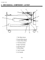
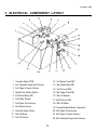
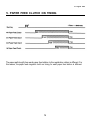
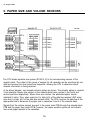
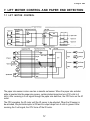
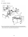
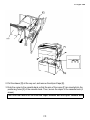
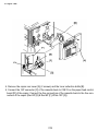
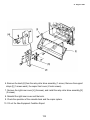
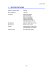
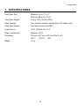
31 August 1989
1. SPECIFICATIONS
Copy Paper Size:
Maximum: A3 or 11” x 17”
Minimum: B6 or 5½” x 8½”
Copy Paper Weight:
50 g to 110 g (14 Ib to 28 lb)
Paper Capacity:
Two universal cassettes holding about 500 sheets each
Paper Feed System:
Feed and reverse roller (FRR)
Power Source:
100 V, 50 Hz/60 Hz, 0.6 A
Power Consumption:
Maximum: 60 W
Dimensions:
745 mm x 447 mm x 612 mm (W x D x H)
(18.2”) (25”)
(30.4”)
Weight:
19 kg
7-1
31 August 1989
2. MECHANICAL COMPONENT LAYOUT
1. Third Relay Sensor
2. Second Relay Sensor
3. Second Relay Rollers
4. Third Relay Rollers
5. Paper Feed Roller
6. Separation Roller
7. Pick-up Roller
8. Fourth Cassette
9. 3rd Cassette
7-2
31 August 1989
3. ELECTRICAL COMPONENT LAYOUT
1. Cassette Bank PCB
12. 3rd Paper Feed MC
2. 3rd Cassette Paper End Sensor
13. 3rd Feed Relay MC
3. 3rd Paper Volume Sensor
14. 3rd Pick-up SOL
4. Right Door Safety Switch
15. 4th Paper Feed MC
5. 2nd Feed Relay MC
16. 4th Lift Sensor
6. 3rd Relay Sensor
17. 4th Pick-up SOL
7. 3rd Paper Size Sensor
18. 4th Lift Motor
8. 2nd Relay Sensor
19. Cassette Bank Motor Capacitor
9. Cassette Bank Motor
20. 4th Paper Size Sensor
10. 3rd Lift Motor
21. 4th Paper Volume Sensor
11. 3rd Lift Sensor
22. 4th Cassette Paper End Sensor
7-3
31 August 1989
4. OVERVIEW
This unit adds two additional universal cassettes (500 sheets each), which are the third and
fourth cassettes, to the copier.
Both the third and fourth paper feed stations have an FRR (Feed and reverse roller)
mechanism which is similar to the feed system of the copier, except for the following items.
1. Both third and fourth cassette bottom plates can be lowered mechanically to load paper
without removing the cassettes.
2. The pick-up, paper feed, and separation rollers are driven by the bank motor (an ac
motor) via the third and fourth paper feed clutches and gears.
The second and third relay rollers transport paper to the registration rollers of the copier. They
are driven by the bank motor. The second and third relay sensors monitor the paper feed
timing.
To facilitate loading paper and removing misfed paper, the following four mechanisms are
included in the bank.
1. Front Loading Mechanism
The paper supply unit can be pulled all the way out. This mechanism makes paper loading
and misfeed removal easy.
2. Right Cover
Misfed paper remaining in between the bank and copier can be removed by opening this
cover.
3. Slide Mechanism
When the LCT is installed on the right side of the bank, it is impossible to open the right
cover for misfeed removal. The slide mechanism, however, slides the paper supply unit to
the left (after pulling the paper supply unit all the way out) for removal of misfed paper.
4. Second Relay Roller Drive Mechanism
This mechanism allows you to manually rotate the second relay roller to remove the misfed
paper.
7-4
31 August 1989
5. PAPER FEED CLUTCH ON TIMING
The paper path length from each paper feed station to the registration rollers is different. For
this reason, the paper feed magnetic clutch on timing for each paper feed station is different.
7-5
31 August 1989
6. PAPER SIZE AND VOLUME SENSORS
The CPU sends separate scan pulses (SCAN 3, 4) to the corresponding sensors of the
cassette bank. The output of this group of sensors for all cassettes can be monitored by one
data bus because the scan pulses are sequential, allowing the CPU to determine which
cassette information is being received.
In the above diagram, two example actuator plates are shown. The actuator plates in cassette
3 and cassette 4 paper size sensors in the cassette bank have notches in the fourth and
second positions respectively. Where there are notches, the photointerruptors remain
activated (0 volts). Thus, when scan line 3 is high, bit 4 of the data bus remains LOW; when
scan line 4 is high, bit 2 of the data bus remains LOW. The CPU monitors the data bus at the
appropriate time to determine the paper size in cassettes 3 and 4 of the cassette bank.
Signals from the volume sensors are sent to the copier main PCB through the cassette bank
PCB and the paper feed control PCB; however, the copier operation panel will not indicate
how much paper remains in the cassettes.
7-6
31 August 1989
7. LIFT MOTOR CONTROL AND PAPER END DETECTION
7.1 LIFT MOTOR CONTROL
The paper size sensor is also used as a cassette set sensor. When the paper size actuator
plate is inserted into the paper size sensor, certain photointerruptors turn off (0 volts to 5
volts). After receiving a 5-volt signal through the paper size data bus, the CPU turns on the lift
motor.
The CPU energizes the lift motor until the lift sensor is de-actuated. When the lift sensor is
de-actuated, the photointerruptor is ON and its output drops from 5 volts to ground. After
receiving the 0 volt signal, the CPU turns off the lift motor.
7-7
31 August 1989
7.2 PAPER END DETECTION
After the last sheet of paper from a cassette has been fed, the Load Paper indicator lights.
Photointerruptors are used for the third and fourth paper end sensors. When either one of the
sensors is actuated, the photointerruptor turns off (0 volts to 5 volts). The CPU detects paper
end by monitoring the output of these sensors.
As with the paper volume and paper size sensors, the CPU uses the same scan pulses to
monitor these sensors.
7-8
31 August 1989
8. INSTALLATION
8.1 Accessory Check
Check the quantity and condition of the accessories in the box according to the following list:
1. Relay Rollers Drive Ass’y
2. Screw - M4 x 8
3. Multiple Language Decal (220/240V only)
4. NECR
5. Envelope - NECR (115V only)
1
6
1
1
1
7-9
31 August 1989
8.2 Installation Procedure
1. Remove the external strips of tape [A]. Remove the right cover (4 screws) and the left
cover (2 screws), then remove the right and left retainers [B] (4 screws each) and the front
and rear retainers [C] (1 screw each) from the paper feed unit.
7-10
31 August 1989
2. Pull the drawer [D] all the way out, and remove the strips of tape [E].
3. Dock the copier to the cassette bank so that the pins of the copier [F] are inserted into the
positioning holes [G] of the cassette bank. Then, secure the copier to the cassette bank (4
screws).
CAUTION: Be careful not to crush the copier harness and the copier cassette bank.
7-11
31 August 1989
4. Remove the copier rear cover [A] (2 screws) and the toner collection bottle [B].
5. Connect the 14P connector [C] of the cassette bank to CN413 on the paper feed control
board [D] of the copier. Connect the free connectors of the cassette bank to the free connectors of the copier (Red 2P [E] & Red 8P [F], White 10P [G]).
7-12
31 August 1989
6. Remove the knob [H] from the relay roller drive assembly (1 screw). Remove the support
straps [I] (1 screws each), the copier front cover (2 knob screws).
7. Remove the right inner cover [J] (4 screws), and install the relay roller drive assembly [K]
(2 screws).
8. Reinstall the right inner cover and the knob.
9. Check the operation of the cassette bank and the copier system.
10. Fill out the New Equipment Condition Report.
7-13