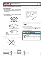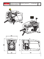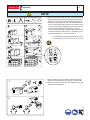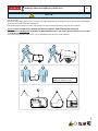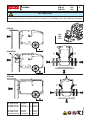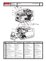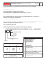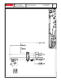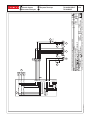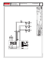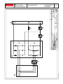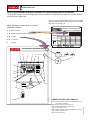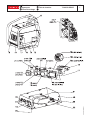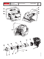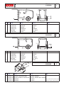
1
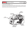
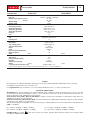
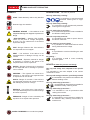
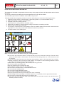
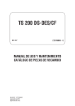
TS 200 DS-DES/CF 0211 272709003 - GB USE AND MAINTENANCE MANUAL SPARE PARTS CATALOG © MOSA 04/11/02 27270M00 preparato da UPT approvato da DITE DESCRIPTION OF THE MACHINE REV.0-02/11 TS 200 DS-DES/CF M 0 The TS 200 engine driven welder ia a unit which ensures the function as: a) a current source for are welding b) a current source for the auxiliary generation Unit meant for industrial and professional use, powered by an endothermic engine; it is composed of various main parts such as: engine, alternator, electric and electronic controls, the fairing or a protective structure. The assembling is made on a steel structure, on which are provided elastic support which must damp the vibrations and also eliminate sounds which would produce noise. ENGINE FRONT PANEL FRAME VIBRATION DAMPER ALTERNATOR © MOSA REV.3-02/09 M Quality system 01 UNI EN ISO 9001 : 2008 The certifying institute, ICIM, which is a member ofthe International Certification Network IQNet, awarded the official approval to MOSA after anexamination of its operations at the head office andplant in Cusago (MI), Italy. This certification is not a point of arrival but a pledgeon the part of the entire company to maintain a levelof quality of both its products and services whichwill continue to satisfy the needs of its clients, aswell as to improve the transparency and thecommunications regarding all the company’s activesin accordance with the official procedures and inharmony with the MOSA Manual of Quality. The advantages for MOSA clients are: ·Constant quality of products and services at thehigh level which the client expects; ·Continuous efforts to improve the products andtheir performance at competitive conditions; ·Competent support in the solution of problems; ·Information and training in the correct applicationand use of the products to assure the security ofthe operator and protect the environment; ·Regular inspections by ICIM to confirm that therequirements of the company’s quality systemand ISO 9001 are being respected. All these advantages are guaranteed by the CERTIFICATE OF QUALITY SYSTEM No.0192 issued by ICIM S.p.A. - Milano (Italy ) - www.icim.it 10/10/02 M01-GB MOSA has certified its quality system according to UNI EN ISO 9001:2008 to ensure a constant, highquality of its products. This certification covers thedesign, production and servicing of engine drivenwelders and generating sets. M 01 M 1.01 M 1.1 M 1.4 M 1.5 M 2 - ... M 2.5 -…. M 2.6 M 2.7 M3 M 4.1 M 6.5 M 20 M 21 M 22 M 31 M 34 M 37 M 39.6 M 40.1 M 43... M 45 M 46 M 53 M 55 M 60 M 61-….. QUALITY SYSTEM COPYRIGHT NOTES MARCHIO CE DATI TECNICI SYMBOLS AND SAFETY PRECAUTIONS INSTALLATION AND ADVICE BEFORE USE INSTALLATION AND ADVICE INSTALLATION UNPACKING TRANSPORT AND DISPLACEMENTS ASSEMBLY: CTM 6/2 - PB3 SET-UP FOR OPERATION STARTING THE ENGINE STOPPING THE ENGINE CONTROLS USE AS A WELDER USE AS A GENERATOR ENGINE PROTECTION TROUBLE SHOOTING MAINTENANCE STORAGE CUST OFF DIMENSIONS RECOMMENDED ELECTRODES ELECTRICAL SYSTEM LEGEND ELECTRICAL SYSTEM R 1 DR ... SPARE PARTS TABLES SPARE PARTS TS 200 DS-DES/CF M 1 04/11/02 27270-GB REV.1-02/11 Index Copyright © MOSA GE_, MS_, TS_, EAS M 1.01 1.0-10/02 ATTENTION This use and maintenance manual is an important part of the machines in question. The assistance and maintenance personel must keep said manual at disposal, as well as that for the engine and alternator (if the machine is synchronous) and all other documentation about the machine. We advise you to pay attention to the pages concerning the security (see page M1.1). © All rights are reserved to said Company. It is a property logo of MOSA division of B.C.S. S.p.A. All other possible logos contained in the documentation are registered by the respective owners. ➠ The reproduction and total or partial use, in any form and/or with any means, of the documentation is allowed to nobody without a written permission by MOSA division of B.C.S. S.p.A. To this aim is reminded the protection of the author’s right and the rights connected to the creation and design for communication, as provided by the laws in force in the matter. In no case MOSA division of B.C.S. S.p.A. will be held responsible for any damaga, direct or indirect, in relation with the use of the given information. 10/10/02 M1-01-GB MOSA division of B.C.S. S.p.A. does not take any responsibility about the shown information on firms or individuals, but keeps the right to refuse services or information publication which it judges discutible, unright or illegal. Notes © MOSA GE_, MS_, TS_, EAS_ M 1-1 1.0-10/02 INFORMATION Dear Customer, We wish to thank you for having bought from MOSA a high quality set. Our sections for Technical Service and Spare Parts will work at best to help you if it were necessary. To this purpose we advise you, for all control and overhaul operations, to turn to the nearest authorized Service Centre, where you will obtain a prompt and specialized intervention. ☞ In case you do not profit on these Services and some parts are replaced, please ask and be sure that are used exclusively original MOSA parts; this to guarantee that the performances and the initial safety prescribed by the norms in force are re-established. ☞ The use of non original spare parts will cancel immediately any guarantee and Technical Service obligation from MOSA. NOTES ABOUT THE MANUAL Before actioning the machine please read this manual attentively. Follow the instructions contained in it, in this way you will avoid inconveniences due to negligence, mistakes or incorrect maintenance. The manual is for qualified personnel, who knows the rules: about safety and health, installation and use of sets movable as well as fixed. INFORMATION OF GENERAL TYPE In the envelope given together with the machine and/or set you will find: the manual for Use Maintenance and Spare Parts, the manual for use of the engine and the tools (if included in the equipment), the guarantee (in the countries where it is prescribed by law). Our products have been designed for the use of generation for welding, electric and hydraulic system; ANY OTHER DIFFERENT USE NOT INCLUDED IN THE ONE INDICATED, relieves MOSA from the risks which could happen or, anyway, from that which was agreed when selling the machine; MOSA excludes any responsibility for damages to the machine, to the things or to persons in this case. Our products are made in conformity with the safety norms in force, for which it is advisable to use all these devices or information so that the use does not bring damage to persons or things. While working it is advisable to keep to the personal safety norms in force in the countries to which the product is destined (clothing, work tools, etc.). Do not modify for any motive parts of the machine (fastenings, holes, electric or mechanical devices, others..) if not duly authorized in writing by MOSA: the responsibility coming from any potential intervention will fall on the executioner as in fact he becomes maker of the machine. You must remember that, in case you have difficulties for use or installation or others, our Technical Service is always at your disposal for explanations or interventions. You must take into account that some figures contained in it want only to identify the described parts and therefore might not correspond to the machine in your possession. ☞ Notice: this manual does not engage MOSA, who keeps the faculty, apart the essential characteristics of the model here described and illustrated, to bring betterments and modifications to parts and accessories, without putting this manual uptodate immediately. 10/10/02 M 1-1 GB The manual for Use Maintenance and Spare Parts is an integrant part of the product. It must be kept with care during all the life of the product. In case the machine and/or the set should be yielded to another user, this manual must also given to him. Do not damage it, do not take parts away, do not tear pages and keep it in places protected from dampness and heat. REV.5-03/11 CE MARK M 1.4 Any of our product is labelled with CE marking attesting its conformity to appliable directives and also the fulfillment of safety requirements of the product itself; the list of these directives is part of the declaration of conformity included in any machine standard equipment. Here below the adopted symbol: CE marking is clearly readable and unerasable and it can be either part of the data-plate. The indication is shown in a clear, readable and indeleble way on a sticker. 10/10/02 M1-4 GB Furthermore, on each model it is shown the noise level value; the symbol used is the following: REV.0-06/10 Dichiarazione conformità Declaration of conformity Déclaration de conformité BCS S.p.A. Konformitätserklärung Declaración de conformidad M 1.4.1 Stabilimento di Cusago, 20090 (MI) - Italia V.le Europa 59 Tel.: +39 02 903521 Fax: +39 02 90390466 Sede legale: Via Marradi 1 20123 Milano - Italia DICHIARAZIONE DI CONFORMITA' Déclaration de Conformité – Declaration of Conformity – Konformitätserklärung Conformiteitsverklaring – Declaración de Conformidad BCS S.p.A. dichiara sotto la propria responsabilità che la macchina: BCS S.p.A. déclare, sous sa propre responsabilité, que la machine: BCS S.p.A. declares, under its own responsibility, that the machine: BCS S.p.A. erklärt, daß die Aggregate: BCS S.p.A. verklaard, onder haar eigen verantwoordelijkheid, dat de machine: BCS S.p.A. declara bajo su responsabilidad que la máquina: GRUPPO ELETTROGENO DI SALDATURA / WELDING GENERATOR GRUPPO ELETTROGENO / POWER GENERATOR Marchio / Brand : _MOSA_____________________________________________ Modello / Model : ______________________________________________ Matricola / Serial number : ______________________________ è conforme con quanto previsto dalle Direttive Comunitarie e relative modifiche: est en conformité avec ce qui est prévu par les Directives Communautaires et relatives modifications: conforms with the Community Directives and related modifications: mit den Vorschriften der Gemeinschaft und deren Ergänzungen übereinstimmt: in overeenkomst is met de inhoud van gemeenschapsrichtlijnemen gerelateerde modificaties: comple con los requisítos de la Directiva Comunitaria y sus anexos: 2006/42/CE - 2006/95/CE - 2004/108/CE Nome e indirizzo della persona autorizzata a costituire il fascicolo tecnico : Nom et adresse de la personne autorisée à composer le Dossier Technique : Person authorized to compile the technical file and address : Name und Adresse der zur Ausfüllung der technischen Akten ermächtigten Person : Persoon bevoegd om het technische document , en bedrijf gegevens in te vullen Nombre y dirección de la persona autorizada a componer el expediente técnico : ing. Benso Marelli - Amministratore Delegato / CEO; V.le Europa 59, 20090 Cusago (MI) - Italy _______________ Ing. Benso Marelli Amministratore Delegato CEO MM 083.0 04/06/10 M1.4.1 Cusago, REV.1-02/11 Technical data Technical data TS 200 DS-DES/CF TS 200 DS/CF D.C. WELDING C.C. Duty cycle Welding current regulation (I scale) (II scale) Welding voltage Welding voltage GENERATOR Self-excited, self-regulated three-phase, asynchronous H Mark / Model Yanmar / L 100 N Type / Cooling system Diesel 4-Stroke / air Cylinders / Displacement 1 / 435 cm3 Output 6.5 kW (8.8 HP) Speed 3000 rpm Fuel consumption (Welding 60%) 1 l/h Engine oil capacity 1.6 l Starter recoil GENERAL SPECIFICATIONS TS 200 DES/CF 190A/35% - 160A/60% - 120A/100% 20 - 100A 90 - 190A 98V 20-27V Three-phase generation 6 kVA / 400 V / 8.7 A Single-phase generation 5 kVA / 230 V / 21.7 A Single-phase generation 2.5 kVA / 110 V / 22.7 A Single-phase generation 2 kVA / 48 V / 41.6 A Frequency 50 Hz Cos ϕ 0.8 ALTERNATOR Self-excited, self-regulated, brushless Type Insulating class ENGINE M 1.5 Tank capacity 5.5 l Running time (Welding 60%) 5.5 h Protection IP 23 *Dimensions Lxwxh (mm) 900x550x622 *Weight 130 Kg **Acoustic power LwA (pressure LpA) 99 LWA (74 dB(A) - 7 m) electric 131 Kg *Dimensions and weight are inclusive of all parts without wheels and towbar CTM. - ** For fixed installation only POWER Declared power according to ISO 3046-1 (temperature 25°C, 30% relative hummidity, altitude 100 m above sea level). It’s admitted overload of 10% each hour every 12 h. In an approximative way one reduces: of 1% every 100 m altitude and of 2.5% for every 5°C above 25°C. ACOUSTIC POWER LEVEL ATTENTION: The concrete risk due to the machine depends on the conditions in which it is used. Therefore, it is up to the enduser and under his direct responsibility to make a correct evaluation of the same risk and to adopt specific precautions (for instance, adopting a I.P.D. -Individual Protection Device) Acoustic Noise Level (LWA) - Measure Unit dB(A): it stands for acoustic noise released in a certain delay of time. This is not submitted to the distance of measurement. Acoustic Pressure (Lp) - Measure Unit dB(A): it measures the pressure originated by sound waves emission. Its value changes in proportion to the distance of measurement. The here below table shows examples of acoustic pressure (Lp) at different distances from a machine with Acoustic Noise Level (LWA) of 95 dB(A) Lp a 1 meter = 95 dB(A) - 8 dB(A) = 87 dB(A) Lp a 4 meters = 95 dB(A) - 20 dB(A) = 75 dB(A) Lp a 7 meters = 95 dB(A) - 25 dB(A) = 70 dB(A) Lp a 10 meters = 95 dB(A) - 28 dB(A) = 67 dB(A) PLEASE NOTE: the symbol when with acoustic noise values, indicates that the device respects noise emission limits according to 2000/14/CE directive. 2000 / 14 / CE 1.0-11/99 SYMBOLS IN THIS MANUAL - The symbols used in this manual are designed to call your attention to important aspects of the operation of the machine as well as potential hazards and dangers for persons and things. IMPORTANT ADVICE - Advice to the User about the safety: +N.B.: The information contained in the manual can be changed without notice. Potential damages caused in relation to the use of these instructions will not be considered because these are only indicative. Remember that the non observance of the indications reported by us might cause damage to persons or things. It is understood, that local dispositions and/or laws must be respected. WARNING ! Situations of danger - no harm to persons or things Do not use without protective devices provided Removing or disabling protective devices on the machine is prohibited. Do not use the machine if it is not in good technical condition The machine must be in good working order before being used. Defects, especially those which regard the safety of the machine, must be repaired before using the machine. M 2 SAFETY PRECAUTIONS ! DANGEROUS This heading warns of an immediate danger for persons as well for things. Not following the advice can result in serious injury or death. ! WARNING This heading warns of situations which could result in injury for persons or damage to things. ! CAUTION To this advice can appear a danger for persons as well as for things, for which can appear situations bringing material damage to things. ! IMPORTANT ! NOTE ! ATTENTION These headings refer to information which will assis you in the correct use of the machine and/or accessories. 26/11/99 M2GB © MOSA GE_, MS_, TS_ SYMBOLS AND SAFETY PRECAUTIONS REV.2-06/10 SYMBOLS STOP - Read absolutely and be duly attentive Read and pay due attention ! GENERAL ADVICE - If the advice is not respected damage can happen to persons or things. HIGH VOLTAGE - Attention High Voltage. There can be parts in voltage, dangerous to touch. The non observance of the advice implies life danger. FIRE - Danger of flame or fire. If the advice is not respected fires can happen. HEAT - Hot surfaces. If the advice is not respected burns or damage to things can be caused. EXPLOSION - Explosive material or danger of explosion. in general. If the advice is not respected there can be explosions. WATER - Danger of shortcircuit. If the advice is not respected fires or damage to persons can be caused. SMOKING - The cigarette can cause fire or explosion. If the advice is not respected fires or explosions can be caused. ACIDS - Danger of corrosion. If the advice is not respected the acids can cause corrosions with damage to persons or things. PROHIBITIONS No harm for persons Use only with safety clothing It is compulsory to use the personal protection means given in equipment. Use only with safety clothing It is compulsory to use the personal protection means given in equipment. Use only with safety protections It is a must to use protection means suitable for the different welding works. Use with only safety material It is prohibited to use water to quench fires on the electric machines. Use only with non inserted voltage It is prohibited to make interventions before having disinserted the voltage. No smoking It is prohibited to smoke while filling the tank with fuel. No welding It is forbidden to weld in rooms containing explosive gases. ADVICE No harm for persons and things Use only with safety tools, adapted to the specific use It is advisable to use tools adapted to the various maintenance works. Use only with safety protections, specifically suitable It is advisable to use protections suitable for the different welding works. Use only with safety protections It is advisable to use protections suitable for the different daily checking works. WRENCH - Use of the tools. If the advice is not respected damage can be caused to things and even to persons. Use only with safety protections It is advisable to use all protections while shifting the machine. PRESSION - Danger of burns caused by the expulsion of hot liquids under pressure. Use only with safety protections It is advisable to use protections suitable for the different daily checking works.and/or of maintenance. ACCES FORBIDDEN to non authorizad peaple. 26/11/99 M2-1GB © MOSA M 2-1 SYMBOLS AND SAFETY PRECAUTIONS © MOSA ! 1.0-06/00 The installation and the general advice concerning the operations, are finalized to the correct use of the machine, in the place where it is used as generator group and/or welder. Stop engine when fueling CHECKING BOARD Do not smoke, avoid flames, sparks or electric tools when fueling. Unscrew the cap slowly to let out the fuel vapours. ENGINE M 2-5 GE_, MS_, TS_ INSTALLATION AND ADVICE BEFORE USE Slowly unscrew the cooling liquid tap if the liquid must be topped up. The vapor and the heated cooling liquid under pressure can burn face, eyes, skin. Do not fill tank completely. Wipe up spilled fuel before starting engine. Shut off fuel of tank when moving machine (where it is assembled). Do not touch electric devices if you are barefoot or with wet clothes. Always keep off leaning surfaces during work operations. Static electricity can demage the parts on the circuit. An electric shock can kill Avoid spilling fuel on hot engine. Sparks may cause the explosion of battery vapours + FIRST AID. In case the operator shold be sprayed by accident, from corrosive liquids a/o hot toxic gas or whatever event which may cause serious injuries or death, predispose the first aid in accordance with the ruling labour accident standards or of local instructions. Skin contact Wash with water and soap Eyes contact Irrigate with plenty of water, if the irritation persists contact a specialist Ingestion Do not induce vomit as to avoid the intake of vomit into the lungs, send for a doctor Suction of liquids from If you suppose that vomit has entered the lungs (as in case of spontaneous vomit) take the subject to the lungs hospital with the utmost urgency In case of exposure to high concentration of vapours take immediately to a non polluted zone the person involved Inhalation + FIRE PREVENTION. In case the working zone,for whatsoever cause goes on fire with flames liable to cause severe wounds or death, follow the first aid as described by the ruling norms or local ones. EXTINCTION MEANS Carbonate anhydride (or carbon dioxyde) powder, foam, nebulized water Not to be used Avoid the use of water jets Other indications Cover eventual shedding not on fire with foam or sand, use water jets to cool off the surfaces close to the fire Particular protection Wear an autorespiratory mask when heavy smoke is present Useful warnings Avoid, by appropriate means to have oil sprays over metallic hot surfaces or over electric contacts (switches,plugs,etc.). In case of oil sprinkling from pressure circuits, keep in mind that the inflamability point is very low. WARNING ! CAUTION ! WARNING THE MACHINE MUST NOT BE USED IN AREAS WITH EXPLOSIVE ATMOSPHERE 10/06/00 M2-5I ! ! DANGEROUS Appropriated © MOSA 1.0-03/00 PRECAUTION (ENGINE DRIVEN WELDER) GE_, MS_, TS_ M 2-5-1 INSTALLATION AND ADVICE BEFORE USE The operator of the welder is responsible for the security of the people who work with the welder and for those in the vicinity. The security measures must satisfy the rules and regulations for engine driven welders. The information given below is in addition to the local security norms. Estimate possible electromagnetic problems in the work area taking into account the following indications. 1. Telephonic wirings and/or of communication, check wirings and so on, in the immediate vicinity. 2. Radio and television receptors and transmettors. 3. Computer and other checking devices. 4. Critical devices for safety and/or for industrial checks. 5. Peapol who, for instance, use pace-maker, hearing-aid for deaf or something and else. 6. Devices used for rating and measuring. 7. The immunity of other devices in the operation area of the welder. Make sure that other used devices are compatible. If it is the case, provide other additional measures of protection. 8. The daily duration of the welding time. ! WARNING àDo not touch any bare wires, leads or contacts as they may be live and there is danger of electric shock which can cause death or serious burns. The electrode and welding cables, etc. are live when the unit is operating. àDo not touch any electrical parts or the electrode while standing in water or with wet hands, feet or clothes. àInsulate yourself from the work surface while welding. Use carpets or other insulating materials to avoid physical contact with the work surface and the floor. àAlways wear dry, insulating glovers, without holes, and body protection. àDo not wind cables around the body. àUse ear protections if the noise level is high. àKeep flamable material away from the welding area. àDo not weld on containers which contain flamable material. àDo not weld near refuelling areas. àDo not weld on easily flamable surfaces. àDo not use the welder to defrost (thaw) pipes. àRemove the electrode from the electrode holder, when not welding. àAvoid inhaling fumes by providing a ventilation system or, if not possible, use an approved air breather. àDo not work in closed areas where there is no fresh air flow. àProtect face and eyes (protective mask with suitable dark lens and side screens), ears and body (nonflamable protective clothers). 30/03/00 M2-5GB Make sure that the area is safe before starting any welding operation. © MOSA REV.1-06/07 M 2.6 INSTALLATION AND ADVICE INSTALLATION AND ADVICE BEFORE USE GASOLINE ENGINES + Use in open space, air swept or vent exhaust gases, which contain the deathly carbone oxyde, far from the work area. Check that the air gets changed completely and the hot air sent out does not come back inside the set so as to cause a dangerous increase of the temperature. 1,5 m DIESEL ENGINES + Use in open space, air swept or vent exhaust gases far from the work area. 1,5 1,5 m m UT P UICTO AOR TC DISS SU GHAA EX + Make sure that the machine does not move during the work: block it possibly with tools and/or devices made to this purpose. MOVES OF THE MACHINE + At any move check that the engine is off, that there are no connections with cables which impede the moves. PLACE OF THE MACHINE ! POSITION Place the machine on a level surface at a distance of at least 1,5 m from buildings or other plants. ATTENTION For a safer use from the operator DO NOT fit the machine in locations with high risk of flood. Please do not use the machine in weather conditions which are beyond IP protection shown both in the data plate and on page named "technical data" in this same manual. 26/11/99 M2-6GB Maximum leaning of the machine (in case of dislevel) Luftzirkulation und abmessungen Instalación y dimensiones TS 200 DS-DES/CF M 2.7 04/11/02 27270-I REV.2-02/11 Installazione e dimensioni Installation and dimensions Installation et dimensions © MOSA REV.1-02/04 M 3 UNPACKING NOTE ! + Be sure that the lifting devices are: correctly mounted, adequate for the weight of the machine with it’s packaging, and conforms to local rules and regulations. When receiving the goods make sure that the product has not suffered damage during the transport, that there has not been rough handling or taking away of parts contained inside the packing or in the set. In case you find damages, rough handling or absence of parts (envelopes, manuals, etc.), we advise you to inform immediately our Technical Service. For eliminating the packing materials, the User must keep to the norms in force in his country. 1 A B 1)Take the machine (C) out of the shipment packing. Take out of the envelope (A) the user’s manual (B). 2)Read: the user’s manual (B), the plates fixed on the machine, the data plate. C 30/03/00 M3GB 2 © MOSA REV.1-06/10 TRANSPORT AND DISPLACEMENTS COVERED UNITS ! M 4-1 NOTE Transportation must always take place with the engine off, electrical cables and starting battery disconnected and fuel tank empty. Be sure that the lifting devices are: correctly mounted, adequate for the weight of the machine with it’s packaging, and conform to local rules and regulations. Only authorized persons involved in the transport of the machine should be in the area of movement. DO NOT LOAD OTHER PARTS WHICH CAN MODIFY WEIGHT AND BARICENTER POSITION. IT IS STRICTLY FORBIDDEN TO DRAG THE MACHINE MANUALLY OR TOW IT BY ANY VEHICLE (model with no CTM accessory). If you did not keep to the instructions, you could damage the structure of the machine. 15/01/01 M4GB Weight max. per person: 35 kg Total max. weight; 140 kg CTM 6/6UK CTM 6/2 CTM 200 ASSEMBLY © MOSA 1.1-01/04 PB1 PB2 PB3 M 6 ATTENTION The CTM accessory cannot be removed from the machine and used separately (actioned manually or following vehicles) for the transport of loads or anyway for used different from the machine movements. Note: Lift the machine and assemble the parts as shown in the drawing CTM 6/2 PB1 PB2 PB3 CTM 6/6UK GE 7000 BS/GS CTM 200 GE 6000 DS/GS CTM 6/2 GE 6000 DES/GS CTM 6/6UK C 145 mm A 310 mm B 400 mm GE 7500 BS/GS CTM 200 GE 6500 DS/GS CTM 6/2 GE 6500 DES/GS CTM 6/6UK C 205 mm A 400 mm B 400 mm 21/05/03 M6GB CTM 200 © MOSA 1.1-09/05 Set-up for operation (Engine diesel) Air cooled systems OIL BATH AIR FILTER BATTERY WITHOUT MAINTENANCE Connect the cable + (positive) to the pole + (positive) of the battery (after having taken away the protection), by properly tightening the clamp. Fill the air filter using the same engine oil up to the level indicated on the filter. FUEL Check the state of the battery from the colour of the warning light which is in the upper part. ! - Green colour: battery OK - Black colour: battery to be recharged - White colour: battery to be replaced DO NOT OPEN THE BATTERY. LUBRICANT RECOMMENDED OIL MOSA recommends selecting AGIP engine oil. Refer to the label on the motor for the recommended products. M 20 ATTENTION Do not smoke or use open flames during refuelling operations, in order to avoid explosions or fire hazards. Fuel fumes are highly toxic; carry out operations outdoors only, or in a wellventilated environment. Avoid accidentally spilling fuel. Clean any eventual leaks before starting up motor. Refill the tank with good quality diesel fuel, such as automobile type diesel fuel, for example. For further details on the type of diesel fuel to use, see the motor operating manual supplied. Do not fill the tank completely; leave a space of approx. 10 mm between the fuel level and the wall of the tank to allow for expansion. ! ATTENTION It is dangerous to fill the motor with too much oil, as its combustion can provoke a sudden increase in rotation speed. DRY AIR FILTER Check that the dry air filter is correctly installed and that there are no leaks around the filter which could lead to infiltrations of non-filtered air to the inside of the motor. In rigid environmental temperature conditions, use special winterized diesel fuels or specific additives in order to avoid the formation of paraffin. GROUNDING CONNECTION The grounding connection to an earthed installation is obligatory for all models equipped with a differential switch (circuit breaker). In these groups the generator star point is generally connected to the machine’s earthing; by employing the TN or TT distribution system, the differential switch guarantees protection against indirect contacts. In the case of powering complex installations requiring or employing additional electrical protection devices, the coordination between the protection devices must be verified. For the grounding connection, use the terminal (12); comply to local and/or current regulations in force for electrical installations and safety. 16/07/03 M20-R-A-GB Please refer to the motor operating manual for the recommended viscosity. REFUELLING AND CONTROL: Carry out refuelling and controls with motor at level position. 1. Remove the oil-fill tap (24) 2. Pour oil and replace the tap 3. Check the oil level using the dipstick (23); the oil level must be comprised between the minimum and maximum indicators. REV.0-11/02 Stopping the engine TS 200 DS-DES/CF M 22 check daily 7)push the decompression lever down and release NOTE ! Do not alter the primary conditions of regulation and do not touch the sealed parts. 8)hold the starting handle firmly MANUAL RECOIL VERSION 9)pull the rope hard and fast. Pull it all the way out. Use two hands if necessary. 1)Open the fuel cock ELECTRIC STARTING VERSION Effect the operations 1), 2) and 7) as reported in the para Recoil starter. OFF 2)turn the welding current control knob (16T) to the maximum (fully counterclockwise) 3)hold the starting handle properly ON START Turn the starting key (Q1) completely clockwise, until the motor starts. Let the engine run for some minutes before drawing the load. + In case of unsuccessful start-up, do not insist for longer than 5 seconds. Wait 10 seconds before attempting another startup. Emergency recoil start Turn the starting key (Q1) in “ON” position and repeat the process of recoil starting. 4)pull the starting handle slowly... CAUTION ! RUNNING IN During the first 50 hours do not use the unit at more than 60% of full load. Check the oil level regularly. 6)then return it slowly 04/11/02 27270-GB 5)... until you feel resistance ATTENTION ! If battery is not connected, disconnect voltage regulator to prevent damage. Stopping the engine REV.0-11/02 TS 200 DS-DES/CF M 22 + Before stopping the engine it is compulsory to stop the load: -shut off any loads which are connected to the unit auxiliary outputs; -disconnect the electric protection device (D); - stop welding stopping the engine: -Reduce the speed of the engine turning the knob (16/T) on the MIN position (counter clockwise) and let it idle for about 3 minutes -Turn off the engine turning the knob (16/T) on the position STOP (completely counter clockwise). Electric starting version OFF ON START Remove the key (Q1) turning it counter clockwise, OFF position, then take it out. + NB.: for safety reason the key must be kept by qualified personel. 04/11/02 27270-GB Shut the fuel cock. Pos. 9 10 12 15 16 22 26 27 59B D L N1 O1 Q1 S1 T Z2 Descrizione Presa di saldatura (+) Presa di saldatura (-) Presa di messa a terra Presa di corrente in c.a. Comando acceler./puls. marcia Filtro aria motore Tappo serbatoio Silenziatore di scarico Protezione termica corrente aux Interruttore differenziale (30mA) Spia luminosa corrente alternata Spia carica batteria Spia lumin. press. olio/oil alert Chiave di avviamento Batteria Regolatore corrente di saldatura Interruttore magnetotermico Bedienelemente Mandos Description Welding socket ( + ) Welding socket ( - ) Earth terminal A.C. socket Accelerator lever Engine air filter Fuel tank cap Muffler Aux current thermal switch G.F.I. A.C. output indicator Battery charge warning light Oil press.warning light/oil alert Starter key Battery Welding current regulator Thermal-magnetic circ.breaker TS 200 DS-DES/CF Description Prise de soudage ( + ) Prise de soudage ( - ) Prise de mise à terre Prises de courant en c.a. Commande accélér./bouton marche Filtre air moteur Bouchon - réservoir Silencieux d’échappement Protection thermique courant aux. lnterrupteur différentiel Voyants tension alternative Voyant charge batterie Voyant lumin. press.huile / oil alert Clé de démarrage Batterie Régulateur courant soudage lnterrupteur magnétothermique M 31 Descripción Toma de soldadura ( + ) Toma de soldadura ( - ) Toma de puesta a tierra Toma de corriente en c.a Mando de acel./pulsador marcha Filtro aire motor Tapón depósito Silenciador de descarga Protección térmica corr. aux Interruptor diferencial (30 mA) Indicadores luminosos c. alter. Piloto carga bateria Indic.lum.pres. aceite/oil alert Llave de arranque Batería Regulador corr. de soldadura Interruptor magnetotérmico 04/11/02 27270-I REV.1-04/07 Comandi Controls Commandes REV.0-11/02 Use as a welder TS 200 DS-DES/CF M 34 This symbol (Norm EN 60974-1 security standards for arc welders) signifies that the welders can be used in areas with increased risk of electrical shock. CONNECT WELDING CABLES For direct current electrode positive, connect work cable to negative (-) terminal and electrode holder to positive (+) terminal. For direct current electrode negative, reverse cable connections. Turn them clockwise to lock them in position. Loose plugs will result in poor welding and damage to both plug and socket. PUSH AND TWIST WELDING CURRENT REGULATION Once the welding current range has been chosen by attaching the electrode holder lead to the corresponding socket, the welding current is adjusted by turning the knob on the front panel. The knob regulates the rpm of the engine. ATTENTION To reduce the risk of electromagnetic interference, keep the welding cable length short and keep them on or near the ground. Ensure that the machine is grounded. If possible, welding operations should not be done near sensitive electronic devices. 04/11/02 27270-GB ! ! WARNING It is absolutely forbidden to connect the unit to the public mains and/or another electrical power source . Areas for which access by non-authorized personnel is forbidden are: - the control panel (at the front) - the endothermic motor discharge. ENGINE SPEED FOR CORRECT VOLTAGE AND FREQUENCY Turn the welding current regulating knob fully clockwise to put the engine at its maximum rpm. If the engine is not at full rpm the voltage and the frequency of the auxiliary power will not be correct. At no load the voltage can be 10% above nominal and at full load the voltage can be 10% below nominal. PLUGS AND CABLES Before connecting a load to the socket check that the cables are in good condition and that the plug is wired correctly. POWER ON LIGHT The light (L), located above each socket, lights up when there is power available from the socket. +If the warning light does not light, check that the engine is at maximum rpm, that the GFI (ground fault interrupter) is inserted and that the circuit breaker is functioning. When drawing power from more than one socket at the same time, the power available is that indicated for each socket but the total cannot exceed the maximum shown on the rating plate. GROUND FAULT INTERRUPTOR SWITCH The high-sensitivity ground fault interruptor switch [G.F.I.] (30mA) (D), guarantees protection against indirect contacts due to faulty ground currents . When the G.F.I. switch picks up a faulty ground current that is higher than 30mA, it intervenes by immediately cutting off tension to the AC sockets. In case of intervention by this protection feature, reset the G.F.I. switch, bringing the lever to the ON position. M 37 In case of another intervention, verify that no faulty tools are connected, or replace the G.F.I. switch with another of matching specifications and/or contact the Service Department. + Notes: verify the operation of the G.F.I. switch at least once a month by pressing the TEST button. The generator must be running and the differential lever in the ON position. CIRCUIT BREAKERS FOR SOCKETS If you overload the socket the circuit breaker will automatically switch off the power. To reset the circuit breaker, disconnect the load, wait a few seconds for the circuit breaket to cool down and then push the button. The button should stay depressed. If the circuit breaker button does not stay in, let it cool down and try again. If it still will not stay in call the service. PUSH TO RESET ON OFF ON OFF Before reconnecting the load check that the power required is within the rating of the socket. A load which is too large for the socket will cause the circuit breaker to intervene. If, after reconnecting the load, the circuit breaker opens again, check the connections, wires, etc. of the load to find the fault. UNIT FITTED WITH THERMAL MAGNETIC BREAKER Turn on the thermal magnetic breaker (Z2) by pushing it to the ON position. The thermal-magnetic breaker is a safety device which protects the circuìt in the event of a malfunction. In this case the switch disconnects the three and single-phase circuit when in any part of the electric connections a short circuit or a current absorption occurs above the data specified on the label of the unit. 04/11/02 27270-GB REV.0-11/02 TS 200 DS-DES/CF Using the generator REV.1-04/07 Engine protection TS 200 DES/CF TS 200 DES/EL M 39.6 The warning lamps brighten by turning the engine starting key (Q1) and they switch off after some seconds. The engine protection, in case of low oil pressure, is shown by the warning light (O1) without the engine stopping. The same as for as the battery charger warning (O1) light in concerned, the anomaly is shown without the engine stopping. If the trouble should persist, please turn to your Assistance Centre. 04/11/02 27270-GB Once the cause of the problem is removed, to assure the protection it is enough to put the starting key (Q1) to zero (“OFF” position) and start the engine again. TROUBLE SHOOTING 1.0-04/04 PROBLEM No welding current but auxiliary output is OK POSSIBLE CAUSE 1) Defective diode bridge 2) Problem with welding current control (PCB) WHAT TO DO 1) Check the diodes of the bridge 2) Is the remote control switch in the internal position? 3) Check the diodes and SCR’s of the bridge. 4) Check the transformer which supplies power to the welding control PCB. If it is OK replace the PCB 1) Defective diode bridge 1) Check the open circuit welding voltage. If it is OK the diode bridge is OK. If it is 1/3 or 2/3 of the nominal value check the diodes or the SCR’s. 2) If the diode bridge is OK replace the PCB. Weld poorly 2) Problem with welding current control (PCB) Intermittently welds poorly No welding output and no auxiliary power output 1) Bad connections to welding current PCB 1) Check that the pins of the green connectors are clean and making good contact. Check that shunt connections are tight. 2) Problem with welding current control PCB 2) Replace the welding current control PCB 1) Short circuit in wiring 1) Check the wiring inside the welder for a short circuit between cables or to ground. 2) Defective condenser 2) If the wiring is OK, short circuit the condenser to be sure that it is discharged, disconnect all wires from condenser and, using an ohmmeter, check that the condenser is not short circuited. 3) If the condenser box is OK, disconnect all leads from the stator except for those going to the condenser box and check the output from the alternator. If there is no output from the welding winding and the auxiliary winding, replace the stator. 3) Defective stator 4) Short circuited diode bridge ○ ○ M 40.1 ○ only for models with electronic control of welding current. 4) If there is output from all windings reconnect the diode bridge and check if there is welding current. If not the diode bridge is defective. If there is welding current connect the auxiliary power leads one at a time until there is no output; at this point, the short circuit is in that line. 06/04/04 M40-1-I © MOSA TS © MOSA REV.0-06/10 M 43 MAINTENANCE ! WARNING Have qualified personnel do maintenance and troubleshooting work. Stop the engine before doing any work inside the machine. If for any reason the machine must be operated while working inside, pay attention moving parts, hot parts (exhaust manifold and muffler, etc.) electrical parts which may be unprotected when the machine is open. lRemove guards only when necessary to perform maintenance, and replace them when the maintenance requiring their removal is complete. lUse suitable tools and clothes. lDo not modify the components if not authorized. - See pag. M1.1 l NOTE By maintenance at care of the utilizer we intend all the operatios concerning the verification of mechanical parts, electrical parts and of the fluids subject to use or consumption during the normal operation of the machine. For what concerns the fluids we must consider as maintenance even the periodical change and or the refills eventually necessary. Maintenance operations also include machine cleaning operations when carried out on a periodic basis outside of the normal work cycle. The repairs cannot be considered among the maintenance activities, i.e. the replacement of parts subject to occasional damages and the replacement of electric and mechanic components consumed in normal use, by the Assistance Authorized Center as well as by MOSA. The replacement of tires (for machines equipped with trolleys) must be considered as repair since it is not delivered as standard equipment any lifting system. The periodic maintenance should be performed according to the schedule shown in the engine manual. An optional hour counter (M) is available to simplify the determination of the working hours. ! IMPORTANT In the maintenance operations avoid that polluting substances, liquids, exhausted oils, etc. bring damage to people or things or can cause negative effects to surroindings, health or safety respecting completely the laws and/ or dispositions in force in the place. ENGINE and ALTERNATOR PLEASE REFER TO THE SPECIFIC MANUALS PROVIDED. Every engine and alternator manufacturer has HOT surface can hurt you maintenance intervals and specific checks for each model: it is necessary to consult the specific engine or alternator USER AND MAINTENANCE manual. VENTILATION Make certain there are no obstructions (rags, leaves or other) in the air inlet and outlet openings on the machine, alternator and motor. ELECTRICAL PANELS Check condition of cables and connections daily. Clean periodically using a vacuum cleaner, DO NOT USE COMPRESSED AIR. DECALS AND LABELS All warning and decals should be checked once a year and replaced if missing or unreadable. STRENUOUS OPERATING CONDITIONS Under extreme operating conditions (frequent stops and starts, dusty environment, cold weather,extended periods of no load operation, fuel with over 0.5% sulphur content) do maintenance more frequently. BATTERY WITHOUT MAINTENANCE DO NOT OPEN THE BATTERY The battery is charged automatically from the battery charger circuit suppplied with the engine. Check the state of the battery from the colour of the warning light which is in the upper part. - Green colour: battery OK - Black colour: battery to be recharged - White colour: battery to be replaced ! NOTE THE ENGINE PROTECTION NOT WORK WHEN THE OIL IS OF LOW QUALITY BECAUSE NOT CHARGED REGULARLY AT INTERVALS AS PRESCRIBED IN THE OWNER’S ENGINE MANUAL. 05/09/05 M43GB MOVING PARTS can injure © MOSA REV.0-06/07 M 45 STORAGE In case the machine should not be used for more than 30 days, make sure that the room in which it is stored presents a suitable shelter from heat sources, weather changes or anything which can cause rust, corrosion or damages to the machine. + Have qualified personnel prepare the machine for storage. GASOLINE ENGINE Start the engine: lt will run until it stops due to the lack of fuel. Drain the oil from the engine sump and fill it with new oil (see page M25). Pour about 10 cc of oil into the spark plug hole and screw the spark plug, after having rotated the crankshaft several times. Rotate the crankshaft slowly until you feel a certain compression, then leave it. In case of necessity for first aid and of fire prevention, see page. M2.5. ! IMPORTANT In the storage operations avoid that polluting substances, liquids, exhausted oils, etc. bring damage to people or things or can cause negative effects to surroindings, health or safety respecting completely the laws and/or dispositions in force in the place. In case the battery, for the electric start, is assembled, disconnect it. Clean the covers and all the other parts of the machine carefully. Protect the machine with a plastic hood and store it in o dry place. DIESEL ENGINE For short periods of time it is advisable, about every 10 days, to make the machine work with load for 15-30 minutes, for a correct distribution of the lubricant, to recharge the battery and to prevent any possible bloking of the injection system. For long periods of inactivity, turn to the after soles service of the engine manufacturer. Clean the covers and all the other parts of the machine carefully. 04/06/07 M45GB Protect the machine with a plastic hood and store it in a dry place. © MOSA + REV.0-06/07 M 46 CUST OFF Have qualified personnel disassemble the machine and dispose of the parts, including the oil, fuel, etc., in a correct manner when it is to be taken out of service. As cust off we intend all operations to be made, at utilizer’s care, at the end of the use of the machine. This comprises the dismantling of the machine, the subdivision of the several components for a further reutilization or for getting rid of them, the eventual packing and transportation of the eliminated parts up to their delivery to the store, or to the bureau encharged to the cust off or to the storage office, etc. In case of necessity for first aid and fire prevention, see page M2.5. ! IMPORTANT In the cust-off operations avoid that polluting substances, liquids, exhausted oils, etc. bring damage to people or things or can cause negative effects to surroindings, health or safety respecting completely the laws and/or dispositions in force in the place. The several operations concerning the cust off, involve the manipulation of fluids potentially dangerous such as: lubricating oil and battery electrolyte. The dismantling of metallic parts liable to cause injuries or wounds, must be made wearing heavy gloves and using suitable tools. The getting rid of the various components of the machine must be made accordingly to rules in force of law a/o local rules. Particular attention must be paid when getting rid of: lubricating oils, battery electrolyte, and inflamable liquids such as fuel, cooling liquid. The machine user is responsible for the observance of the norms concerning the environment conditions with regard to the elimination of the machine being cust off and of all its components. In case the machine should be cust off without any previous disassembly it is however compulsory to remove: - tank fuel - engine lubricating oil - cooling liquid from the engine - battery 04/06/07 M45GB NOTE: BCS is involved with custing off the machine only for the second hand ones, when not reparable. This, of course, after authorization. RECOMMENDED ELECTRODES © MOSA (In accordance with A.W.S Standard) MS_, TS_ M 55 1.0-10/03 The information here below are to be intended only as indicative since the above norm is much larger. For further details please see the specific norms and/or the manufacturers of the product to be used in the welding process. RUTILE ELECTRODES: E 6013 Easily removable fluid slag, suitable foe welding in all position. Rutile electrodes weld in d.c. with both polarities (electrode holder at + or -) and in a.c.. Suitable for soft steels R-38/45 kg/mm2 . Also for soft steels of lower quality. BASIC ELECTRODES: E 7015 Basic electrrodes wels onlu in d.c. with inverse polarity (+ on the electrode holder) ; there are also types for a.c. Suitable for impure carbon steels. Weld in all position. HIGH YIELD BASIC ELECTRODES: E 7018 The iron contained in the coating increases the quality of metal added. Good mechanical properties. Weld in all position. Electrode holder at + (inverse polarity). Wld deposit of nice aspect, also vertical. Workable; high yield. Suitable for steels with high contens of sulphur (impurities). CELLULOSIC ELECTRODES: E 6010 Cellulosic electrodes weld only in d.c. with polarity + electrode holder - ground clamp. Special for steels run on pipes with R max 55 kg/mm2. Weld in all position. volatile slag. ELECTRODES IDENTIFICATION ACCORDING TO A.W.S. STANDARDS E XX Y Z 2 digits: type of coating and electric power conditions. (see table 3) symbol for "Coated electrode" 2÷3 digits: tesile strenght of the weld deposit. (see table 1) Strenght Number K.s.l. 60 70 80 90 100 110 120 60.000 70.000 80.000 90.000 100.000 110.000 120.000 Table 1 Kg/mm2 42 49 56 63 70 77 84 N° 10 11 12 13 14 15 16 18 20 24 27 28 30 1 2 3 Table 2 for all positions for plane and verticl for plane posotion only Descrizione Cellulose electrodes for d.c. Cellulose electrodes for a.c. Rutile electrode for d.c. Rutile electrode for a.c. High yield rutile electrodes Basic electrodes for d.c. Basic electrodes for c.a. High yield basic electrodes for d.c. (inverse polarity) Acid electrodes for flat or front position welding for d.c. (- pole) and for a.c. High yield rutile electrodes for flat or front plane position welding for d.c. and a.c. High yield acid electrodes for flat or front plane position welding for d.c. (- pole) and a.c.. High yield basic electrodes for flat or front plane position welding for d.c. (inverse polarity) Extra high yield acid electrodes, extra high penetration if required, for flat position welding only for d.c. (- pole) and a.c. Table 3 10/10/03 M55GB 1 digits: welding positions. (see table 2) M 60 ELECTRICAL SYSTEM LEGENDE REV.7-10/09 A B C D E F G H I L M N P Q R S T U V Z X W Y : : : : : : : : : : : : : : : : : : : : : : : Alternator Wire connection unit Capacitor G.F.I. Welding PCB transformer Fuse 400V 3-phase socket 230V 1phase socket 110V 1-phase socket Socket warning light Hour-counter Voltmeter Welding arc regulator 230V 3-phase socket Welding control PCB Welding current ammeter Welding current regulator Current transformer Welding voltage voltmeter Welding sockets Shunt D.C. inductor Welding diode bridge A1 B1 C1 D1 E1 F1 G1 H1 I1 L1 M1 N1 O1 P1 Q1 R1 S1 T1 U1 V1 Z1 W1 X1 Y1 : : : : : : : : : : : : : : : : : : : : : : : : Arc striking resistor Arc striking circuit 110V D.C./48V D.C. diode bridge E.P.1 engine protection Engine stop solenoid Acceleration solenoid Fuel level transmitter Oil or water thermostat 48V D.C. socket Oil pressure switch Fuel warning light Battery charge warning light Oil pressure warning light Fuse Starter key Starter motor Battery Battery charge alternator Battery charge voltage regulator Solenoid valve control PCBT Solenoid valve Remote control switch Remote control and/or wire feeder socket Remote control plug A2 B2 C2 D2 E2 F2 G2 H2 I2 L2 M2 N2 O2 P2 Q2 R2 S2 T2 U2 V2 Z2 W2 X2 Y2 : : : : : : : : : : : : : : : : : : : : : : : : Remote control welding regulator E.P.2 engine protection Fuel level gauge Ammeter Frequency meter Battery charge trasformer Battery charge PCB Voltage selector switch 48V a.c. socket Thermal relay Contactor G.F.I. and circuit breaker 42V EEC socket G.F.I. resistor T.E.P. engine protection Solenoid control PCBT Oil level transmitter Engine stop push-button T.C.1 Engine start push-buttonT.C.1 24V c.a. socket Thermal magnetic circuit breaker S.C.R. protection unit Remote control socket Remote control plug A3 B3 C3 D3 E3 F3 G3 H3 I3 L3 M3 N3 O3 P3 Q3 R3 S3 T3 U3 V3 Z3 W3 X3 Y3 : : : : : : : : : : : : : : : : : : : : : : : : Insulation moitoring E.A.S. connector E.A.S. PCB Booster socket Open circuit voltage switch Stop push-button Ignition coil Spark plug Range switch Oil shut-down button Battery charge diode Relay Resistor Sparkler reactor Output power unit Electric siren E.P.4 engine protection Engine control PCB R.P.M. electronic regulator PTO HI control PCB PTO HI 20 l/min push-button PTO HI 30 l/min push-button PTO HI reset push-button PTO HI 20 l/min indicator A6 B6 C6 D6 E6 F6 G6 H6 I6 L6 M6 N6 O6 P6 Q6 R6 S6 T6 U6 V6 Z6 W6 X6 Y6 : : : : : : : : : : : : : : : : : : : : : : : : Commutator/switch Key switch, on/off QEA control unit Connector, PAC Frequency rpm regulator Arc-Force selector Device starting motor Fuel electro pump 12V c.c. Start Local/Remote selector Choke button Switch CC/CV Connector – wire feeder 420V/110V 3-phase transformer Switch IDLE/RUN Hz/V/A analogic instrument EMC filter Wire feeder supply switch Wire feeder socket DSP chopper PCB Power chopper supply PCB Switch and leds PCB Hall sensor Water heather indicator Battery charge indicator A4 B4 C4 D4 E4 F4 G4 H4 I4 L4 M4 N4 O4 P4 Q4 R4 S4 T4 U4 V4 Z4 W4 X4 Y4 : : : : : : : : : : : : : : : : : : : : : : : : PTO HI 30 l/min indicator PTO HI reset indicator PTO HI 20 l/min solenoid valve PTO HI 30 l/ min solenoid valve Hydraulic oil pressure switch Hycraulic oil level gauge Preheating glow plugs Preheating gearbox Preheating indicator R.C. filter Heater with thermostat Choke solenoid Step relay Circuit breaker Battery charge sockets Sensor, cooling liquid temperature Sensor, air filter clogging Warning light, air filter clogging Polarity inverter remote control Polarity inverter switch Transformer 230/48V Diode bridge, polarity change Base current diode bridge PCB control unit, polarity inverter A7 B7 C7 D7 E7 F7 G7 H7 I7 L7 M7 N7 O7 P7 Q7 R7 S7 T7 U7 V7 Z7 W7 X7 Y7 : : : : : : : : : : : : : : : : : : : : : : : : Transfer pump selector AUT-0-MAN Fuel transfer pump "GECO" generating set test Flooting with level switches Voltmeter regulator WELD/AUX switch Reactor, 3-phase Switch disconnector Solenoid stop timer "VODIA" connector "F" EDC4 connector OFF-ON-DIAGN. selector DIAGNOSTIC push-button DIAGNOSTIC indicator Welding selector mode VRD load 230V 1-phase plug V/Hz analogic instrument Engine protection EP6 G.F.I. relay supply switch Radio remote control receiver Radio remote control trasnsmitter Isometer test push-button Remote start socket A5 B5 C5 D5 E5 F5 G5 H5 I5 L5 M5 N5 O5 P5 Q5 R5 S5 T5 U5 V5 Z5 W5 X5 Y5 : : : : : : : : : : : : : : : : : : : : : : : : Base current switch Auxiliary push-button ON/OFF Accelerator electronic control Actuator Pick-up Warning light, high temperature Commutator auxiliary power 24V diode bridge Y/s commutator Emergency stop button Engine protection EP5 Pre-heat push-button Accelerator solenoid PCB Oil pressure switch Water temperature switch Water heater Engine connector 24 poles Electronic GFI relais Release coil, circuit breaker Oil pressure indicator Water temperature indicator Battery voltmeter Contactor, polarity change Commutator/switch, series/parallel A8 B8 C8 D8 E8 F8 G8 H8 I8 L8 M8 N8 O8 P8 Q8 R8 S8 T8 U8 V8 Z8 W8 X8 Y8 : Transfer fuel pump control : Ammeter selector switch : 400V/230V/115V commutator : 50/60 Hz switch : Cold start advance with temp. switch : START/STOP switch : Polarity inverter two way switch : Engine protection EP7 : AUTOIDLE switch : AUTOIDLE PCB : A4E2 ECM engine PCB : Remote emergency stop connector : V/A digital instruments and led VRD PCB : Water in fuel : Battery disconnect switch : Inverter : Overload led : Main IT/TN selector : NATO socket 12V : Diesel pressure switch : Remote control PCB : Pressure turbo protection : : 26/07/04 M60GB © MOSA Stromlaufplan Esquema eléctrique TS 200 DES/CF M 61.1 04/11/02 27270-I REV.0-11/02 Schema elettrico Electric diagram Schemas electriques L N G SS L 400V/16A N O2 Id 48V/32A R4 D Id L H 230V/16A 20A P4 Alla Pag. To Page Macchina: Machine: Aux. (400T/230M/48M) DT Modifica Modification Denominazione: Da Pag. From Page Denomination: Disegnatore: Designer: Data: Date: Dis. n°: Dwg. n°: 27272.prg Data Date Progetto: Project: 16.11.2006 4 Approvato: Approved: 3 Dis. Appr. Desi. Appr. Pag.n° di n° Page n° of n° N.L. TS 200 DS-DES/CF TS 200 BS/CF 20090-CUSAGO (MI)-ITALY http://www.mosa.it 01.08.2000 27272.S.020-A TS 200 DES/CF Leporace N. La MOSA si riserva a termini di legge la proprieta' del presente disegno con divieto di riprodurlo o comunicarlo a terzi senza sua autorizzazione. Esp. Exp. A Sostituito alternatore (A) con nuovo avvolgimento senza carica batteria. C Id R3 S3 T3 T1 S1 R1 Y S2 T2 RS SS TS R4 R1 S1 T1 Id Stromlaufplan Esquema eléctrique 04/11/02 27270-I A REV.1-04/07 Schema elettrico Electric diagram Schemas electriques M 61.2 L2 R3 S3 T3 RS SS TS R4 D L Z2 230V/16A H 110V/16A I L I L 110V/16A 20A Z2 20A Alla Pag. Macchina: Aux. (230M/110CTEx2) DM Modifica Modification Denominazione: Da Pag. From Page Denomination: Disegnatore: Data: Dis. n°: 27273.prg Data Date Progetto: Project: 16.11.2006 4 Approvato: 3 Dis. Appr. Desi. Appr. Pag.n° di n° Page n° of n° N.L. TS 200 DS-DES/CF Designer: Approved: Date: Dwg. n°: 20090-CUSAGO (MI)-ITALY To Page Machine: http://www.mosa.it TS 200 DES/CF Leporace N. 01.08.2000 27273.S.020-A La MOSA si riserva a termini di legge la proprieta' del presente disegno con divieto di riprodurlo o comunicarlo a terzi senza sua autorizzazione. Esp. Exp. A Sostituito alternatore (A) con nuovo avvolgimento senza carica batteria. C Id S2 T2 T1 S1 R1 Y R1 S1 T1 Id Stromlaufplan Esquema eléctrique 04/11/02 27270-I A REV.0-11/02 Schema elettrico Electric diagram Schemas electriques M 61.3 R3 S3 T3 RS SS TS P3 R3 S3 T3 Alla Pag. To Page Da Pag. From Page 11 2 1 Dis. n°: Drwg. n°: 27272.prg Macchina: Machine: Welding Power Data: Date: - Data Date Progetto: Project: Disegnatore: Designer: W + 100A Modifica Modification Denominazione: Denomination: W O3 12 + 190A 4 Appr. Appr. di n° of n° Approvato: Approved: 4 Dis. Desi. Pag.n° Page n° TS 200 DS-DES/CF TS 200 BS/CF 20090-CUSAGO (MI)-ITALY TS 200 DES/CF Leporace N. 01/08/2000 27272.S.030 http://www.mosa.it La MOSA si riserva a termini di legge la proprieta' del presente disegno con divieto di riprodurlo o comunicarlo a terzi senza sua autorizzazione Esp. Exp. - + - + Z Stromlaufplan Esquema eléctrique 04/11/02 27270-I A Y REV.0-11/02 Schema elettrico Electric diagram Schemas electriques M 61.4 © MOSA R 1 SPARE PARTS LIST 1.0-03/00 MOSA guarantees that any request for spare parts will be satisfied. To keep the machine in full working order, when replacement of MOSA spare parts is required, always ask for genuine parts only. The requested data are to be found on the data plate located on the machine structure, quite visible and easy to consult. Y When ordering the spare parts, it is recommended to indicate: V.le Europa,59 - 20090 CUSAGO (MI) ITALY Tel. +39-02 90352.1 - fax +39-02 90390466 1) Y serial number TYPE SERIAL N° 2) Y model of welder and/or generating set TS 0000 GE 0987654321 3) u n. table 4) u n. position quantity 50 Hz TAVOLA RICAMBI - SPARE PARTS - PIECES DE RECHANGE - ERSATZTEILE EA 1 3 50 Hz 1-3 18 13 17 16 20-21-22 EA 1 12 EA 1 4 12 12 11 0 RS V 500 ST h Hz 60 0 65 A 25 125 20 300 200 TR HOURMETER 55 50 15 10 100 I 2 OFF ON START 8 0 * 19 15 NEUTROCOLLEGATOAMASSA NEUTROCONECTADOAMASA NEUTRALBONDEDTOFRAME NEUTRERACCORDEAUBATI NULLEITERAUFMASSE NULVERBONDENMETMASSA 21-22-23 14 * VE ABBREVIATIONS AND SYMBOLS: (EV) When ordering, specify the engine type and the auxiliary voltage (ER) Engine with recoil starter only (ES) Engine with electric starter only (VE) E.A.S version only. (QM) When ordering, specify the length in meters (VS) Special version only (SR) By request only 22/03/00 R1GB 4-5-6 14/12/986Q16M31 5) Ersatzteile Tabla de ricambios TS 200 DS-DES/CF DR 1 04/11/02 27270-I REV.1-04/07 Ricambi Spare parts Piéces de rechange REV.2-02/11 Ricambi Spare parts Piéces de rechange Ersatzteile Tabla de ricambios TS 200 DS-DES/CF DR 1.1 04/11/02 27270-I Pos. Cod. Descr. Note Fino a/Up to REV.1-04/07 Del. 12/09 - 17/02/09 1 M272702200 MOTORE YANMAR L100AE-DG / YANMAR ENGINE L100AE-DG 1 M256752200 MOTORE YANMAR L100N / YANMAR ENGINE L100N Da/From REV.2-02/11 Del. 12/09 - 17/02/09 1a M272722200 MOTORE YANMAR L100AE-DEG / YANMAR ENGINE L100AE-DEG Fino a /Up to REV.0-11/02 Del. 202/06 - 20/11/06 1a M256862200 MOTORE YANMAR L100AE-DEG / YANMAR ENGINE L100AE-DEG Da/From REV.1-04/07 Del. 202/06 - 20/11/06 Fino a/Up to REV.1-04/07 Del. 285 - 11/01/08 1a M256762200 MOTORE YANMAR L100N / YANMAR ENGINE L100N Da/From REV.2-02/11 Del. 285/07 - 11/01/08 2 M272701050 BARELLA / PROTECTIVE FRAME 5 M272708005 CARENATURA / FRAME 6 M272708205 SCATOLA DI BASE / CASE, BOTTOM HALF 7 M102044400 PRESA DI SALDATURA (-) / WELDING SOCKET (-) 8 M102301310 PRESA DI SALDATURA (+) / WELDING SOCKET (+) 9 M272708235 GRIGLIA DI ASPIRAZIONE / NTAKE GRATE 11 M272707015 COPERCHIO SCATOLA ELETTRICA / COVER ELECTRICAL BOX Fino a/Up to REV.1-04/07 Del.52/08 - 03/03/08 12 M1302220 SPIA 220V / WARNING LIGHT 230V Da/From REV.2-02/11 Del. 52/08 -03/03/08 12 M1302530 SPIA 220V / WARNING LIGHT 220V 12b M1302160 SPIA 110V / WARNING LIGHT 110V Fino a/Up to REV.1-04/07 Del.52/08 - 03/03/08 Da/From REV.2-02/11 Del.52/08 - 03/03/08 12b M1302520 SPIA 110V / WARNING LIGHT110V 13 M307047250 PRESA 110V 16A / EEC SOCKET 110V 16A 2 P+N 13a M218137280 PRESA CEE 48V 32A / EEC SOCKET 48V 32A 14 M306467107 PROTEZIONE TERMICA (AUX) / THERMOPROTECTION 20AMP 250 V 15 M307017240 PRESA 220V 16A / EEC SOCKET 16A, 220V 2P+T 16 M305907270 PRESA CEE 16A 400V 3P+N+T / EEC SOCKET 16A 400V 3P+N+T 17 M219937130 COPERCHIO INTERRUT.DIFFERENZ. / COVER GFI 18 M219937036 STAFFA / BRACKET 19a M105111540 INTERRUTTORE DIFFERENZIALE / GROUNDFAULT INTERRUPTOR (GFI) vers. 400/230/48 19b M220237105 INTERRUTTORE DIFFERENZIALE / GROUNDFAULT INTERRUPTOR vers. 230/110/110 19c M105277325 INTERRUTTORE MAGNETOTERMICO / CIRCUIT BREACKER vers. 230/110/110 20 M309049105 COMANDO ACCELERATORE MOTORE / ENGINE ACCELLERATOR CONTROL era/was 272709105 21 M307017037 STAFFA / BRACKET 22 M307809880 BOX CONDENSATORI 3x80 UF / CAPACITOR BOX 3X80 UF 23 M218017226 MORSETTIERA / TERMINAL BOARD 42 M109019702 MANOPOLA / HAND GRIP 43 M272707010 SCATOLA ELETTRICA / ELECTRICAL BOX 44 M272707020 PANNELLO FRONTALE / FRONT PANEL vers. 400/230/48 45 M272717020 PANNELLO FRONTALE / FRONT PANEL vers. 230/110/110 Da/From REV.1-04/07 Del. 202/06 - 20/11/06 50 M107302460 INTERRUTTORE ACCENS. A CHIAVE / STARTER KEY 51 M1302040 SPIA 12V ROSSA / RED WARNING LIGHT 12V Da/ From REV.1-04/07 Del. 202/06 - 20/11/06 Fino a/Up to REV.1-04/07 Del. 52/08 - 03/03/08 51 M1302500 SPIA 12V ROSSA / RED WARNING LIGHT 12V Da/ From REV.2-02/11 Del. 52/08 - 03/03/08 Ersatzteile Tabla de ricambios TS 200 DS-DES/CF DR 2 04/11/02 27270-I REV.1-04/07 Ricambi Spare parts Piéces de rechange REV.3-02/11 Pos. Rev. Cod. 3 4 B 25 26 27 28 29 30 31 32 32 33 34 35 36 37 38 39 40 B 41 47 47 50 51 52 53 54 55 60 B 61 B Pos. Rev. 3 4 B 25 26 27 28 29 30 31 32 32 33 34 35 36 37 38 39 40 B 41 47 47 50 51 52 53 54 55 60 B 61 B M307012037 M222401035 M272705100 M272704120 M272704100 M271704020 M271704010 M220014100 M232123040 M272703025 M272723025 M232123030 M107011280 M105913045 M232123036 M1001030 M105111290 M105311370 M272506010 M105112020 M105311380 M356403038 M107302460 M1302040 M256027060 M155307107 M256022275 M256027059 M107815043 M107814013 Cod. M307012037 M222401035 M272705100 M272704120 M272704100 M271704020 M271704010 M220014100 M232123040 M272703025 M272723025 M232123030 M107011280 M105913045 M232123036 M1001030 M105111290 M105311370 M272506010 M105112020 M105311380 M356403038 M107302460 M1302040 M256027060 M155307107 M256022275 M256027059 M107815043 M107814013 Ersatzteile Tabla de ricambios Descr. PROTEZIONE ANTIVIBRANTE ANTIVIBRANTE PONTE DIODI REATTORE TRIFASE REATTORE DI LIVELLO SUPPORTO RESISTORE REATTORE COMPLETO FLANGIA ATTACCO MOTORE STATORE AVVOLTO STATORE AVVOLTO ALBERO CON ROTORE TIRANTE FLANGIA PORTA ALTERNATORE TIRANTE CUSCINETTO VENTOLA CON FASCETTA DISTANZIALE CONVOGLIATORE ARIA ANTIVIBRANTE RONDELLA RONDELLADa REV.1-11/06 Del. 91/06 del STARTER A CHIAVE SPIA 12V PANNELLO DISGIUNTORE TERMICO REGOLATORE DI TENSIONE SCATOLA SUPPORTO REGOLATORE BOCCOLA ISOLANTE RONDELLA ISOLANTE Descr. PROTECTION, VIBRATION-DAMPER VIBRATION DAMPER DIODE BRIDGE ASSY REACTOR LEVEL REACTOR SUPPORT RESISTOR COMPLETE REACTOR FLANGE FIXING ENGINE STATOR STATOR SHAFT WITH ROTOR TIE - ROD FLANGE, ALTERNATOR HOLDER TIE-ROD BEARING FAN SPACER AIR DUCT VIBRATION DAMPER WASHER WASHER STARTER KEY RED WARNING LIGHT 12V PANEL THERMAL SWITCH 15A-250V VOLTAGE REGULATOR BOX, SUPPORT REGULATOR BUSH WASHER TS 200 DS-DES/CF DR 2.1 Note era 256011035 Fino a REV.1-11/06 Del. 202/06 - 20/11/06 Da REV.2-04/07 Del. 202/06 - 20/11/06 era 271706010 Fino a REV.0-10/98 Del. 91/06 - 07/06/06 07/06/06 vers.DES-Fino a REV.1-11/06 Del. 202/06 - 20/11/06 vers.DES-Fino a REV.1-11/06 Del. 202/06 - 20/11/06 vers.DES-Fino a REV.1-11/06 Del. 202/06 - 20/11/06 vers.DES-Fino a REV.1-11/06 Del. 202/06 - 20/11/06 vers.DES-Fino a REV.1-11/06 Del. 202/06 - 20/11/06 vers.DES-Fino a REV.1-11/06 Del. 202/06 - 20/11/06 Note was 256011035 Up to REV.1-11/06 Del. 202/06 - 20/11/06 From REV.2-04/07 Del. 202/06 - 20/11/06 was 271706010 Up to REV.0-10/98 Del. 91/06 - 07/06/06 From REV.1-11/06 Del. 91/06 - 07/06/06 vers.DES-Up to REV.1-11/06 Del. 202/06 - 20/11/06 vers.DES-Up to REV.1-11/06 Del. 202/06 - 20/11/06 vers.DES-Up to REV.1-11/06 Del. 202/06 - 20/11/06 vers.DES-Up to REV.1-11/06 Del. 202/06 - 20/11/06 vers.DES-Up to REV.1-11/06 Del. 202/06 - 20/11/06 vers.DES-Up to REV.1-11/06 Del. 202/06 - 20/11/06 04/11/02 27270-I Ricambi Spare parts Piéces de rechange CTM 6/2 212029080 REV.1-10/05 Pos. Rev. 1 2 7 8 9 10 Cod. Descr. Descr. 107012150 107012130 205311160 205311180 6075020 105311650 CAVALLOTTO MANIGLIA ASSALE RONDELLA COPIGLIA U-BOLT HANDLE AXLE WASHER PIN, SPLIT RUOTA WHEEL Note CTM 200 232120130 Pos. Rev. 1 2a 7 8 9 10 Cod. Descr. Descr. 107012150 208101051 205311160 205311180 6075020 105311650 CAVALLOTTO MANIGLIA ASSALE RONDELLA COPIGLIA U-BOLT HANDLE AXLE WASHER PIN, SPLIT RUOTA WHEEL Note PB3 256020040 Pos. 12 13 14 15 15 Cod. 256020549 256029168 256029160 209509150 372859150 Descr. GR.COPERCHIO COMPLETO CESTELLO PORTA BATTERIA CESTELLO P/BATT.+COPERCHIO BATTERIA BATTERIA KA 4 KG 3 Descr. Note COMPLETE COVER BATTERY HOLDER BATTERY HOLDER WITH COVER BATTERY (fino a/up to REV.0 04/97 Del. 74/05 del 15/07/05) BATTERY (da/from REV.1 10/05 Del. 74/05 del 15/07/05) 21/04/97 KA © MOSA KA 3