1
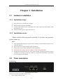
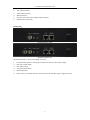
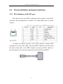
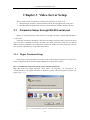
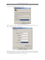
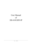
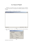
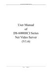
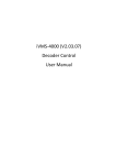
User Manual of Embedded Net DVS
User Manual
of
DS-6001DI/FI
Embedded Decoder Server
(V2.1)
Page 1 Total 26
User Manual of Embedded Net DVS
Index
VERSION DESCRIPTION ................................................................................................................................. 4
CHAPTER 1
INTRODUCTION ................................................................................................................... 5
CHAPTER 2
INSTALLATION ..................................................................................................................... 6
2.1 HARDWARE INSTALLATION ......................................................................................................................... 6
2.1.1
Installation steps................................................................................................................................ 6
2.1.2
Installation notice .............................................................................................................................. 6
2.2 PANEL DESCRIPTION .................................................................................................................................... 6
2.3 THE PIN DEFINITION OF PHYSICS INTERFACES ............................................................................................. 8
2.3.1
PIN definition of RS-232 port ............................................................................................................ 8
2.3.2
PIN definition of RS485 port ........................................................................................................... 10
2.3.3
PIN definition of Ethernet port ........................................................................................................ 10
CHAPTER 3
VIDEO SERVER SETUP ..................................................................................................... 12
3.1 PARAMETER SETUP THROUGH RS-232 SERIAL PORT ................................................................................. 12
3.1.1
Hyper Terminal Setup ...................................................................................................................... 12
3.1.2
Shell Commands Under Hyper Terminal ......................................................................................... 15
3.2 PTZ CONTROL .......................................................................................................................................... 17
CHAPTER 4
UPGRADE FIRMWARE...................................................................................................... 18
4.1 USE SHELL COMMAND AND FTP SERVER ................................................................................................. 18
4.2 USE CLIENT SOFTWARE TO UPGRADE FIRMWARE ...................................................................................... 20
CHAPTER 5
FREQUENT ASK QUESTIONS.......................................................................................... 22
APPENDIX A
DS-6001DI SPECIFICATIONS............................................................................................ 23
APPENDIX B
DS-6001FI SPECIFICATIONS ............................................................................................ 24
APPENDIX C
GOOD LIST........................................................................................................................... 25
APPENDIX D
CUSTOMER INFORMATION CARD ............................................................................... 26
Page 2 Total 26
User Manual of Embedded Net DVS
Thanks for purchase the products of our company. If you have any
request or questions, please contact us immediately.
This manual is applicable for DS-6001DI/FI Decoding Video Server
This manual may contain some technically incorrect places or
printing errors. This manual will be updated on a regular basis without
additional specific notice. The updates will be added into the new version
of this manual. We will readily improve or update the products or
procedures described in the manual.
-3-
User Manual of Embedded Net DVS
Version Description
Version2.1
To be matched with Davinci DVR and DVS.
Version1.5:
To be matched with Version1.5 encoding DVR and DVS.
Version1.4:
To be matched with Version1.4 encoding DVR and DVS.
-4-
User Manual of Embedded Net DVS
Chapter 1 Introduction
DS-6001DI/FI series video server adopts embedded real-time multi-task operation system
(RTOS) and embedded processor, which is completely independent of PC platform and, efficiently
improves system performance. Firmware is burned in FLASH, makes the system more steady and
reliable.
DS-6000DI is a decoder. It can decompress H.264 stream from other Net DVRDVS such as
DS-8000HCI, DS-8000HSI, DS-8000HTI, DS-8000HFI, DS-6000HCI, DS-6001FI, etc. via
network.
DS-6001FI video server is both an encoder and decoder. It has one channel video input, can
compress the video signal into H.264 real time stream, and transmit the live steam through
network. It also has one channel video output to decompress the H.264 stream from other Net
DVRDVS such as DS-8000HCI, DS-8000HSI, DS-8000HTI, DS-8000HFI, DS-6000HCI,
DS-6001FI, etc.
-5-
User Manual of Embedded Net DVS
Chapter 2 Installation
2.1
Hardware installation
2.1.1 Installation steps
1.
2.
3.
Open packing case, and check the integrity;
Take out things needed in installation;
Connect cables needed (video signal input cable, audio signal input cable, RS485 cable
and cable for LAN);
4.
Take out stabilizer power supply and power on.
2.1.2 Installation notice
Please read the following notice carefully. If you have any question,
please contact us.
Notice:
1.
After Opening the packing box, please check carefully to confirm that the goods in it are
consistent with list;
2.
3.
4.
5.
Please read user's manual carefully before installation;
Please power-off all related equipments before installation;
Please check the voltage of power supply to avoid voltage mismatch;
Installation environmental: Do not use it under humidity and high temperature; to keep
ventilation to vent freely, avoid to be walled up; to keep them horizontally, avoid setting
up in the vibration surroundings.
2.2
Panel description
Front panels:
DS-6001DI/FI Front Panel
Interface Instruction (From left to right in turn)
1. Power supply indicator lamp;
-6-
User Manual of Embedded Net DVS
2.
3.
4.
5.
6.
Link indicator lamp;
Tx/Rx indicator lamp;
RS232 interface;
4 Sensor alarm input and 2 replay output interface;
USB interface (reserved).
Back panel:
DS-6001DI Rear Panel
DS-6001FI Rear Panel
Interface Instruction(From left to Right in return):
1. For DS-6001FI, there is video input connector on the left side of video output;
2. One line in audio input;
3. One audio output;
4. UTP network interface;
5. RS-485 interface;
6. Power jack is connected with DC 12V. Please use the stabilizer power supply correctly;
-7-
User Manual of Embedded Net DVS
2.3
The pin definition of physics interfaces
2.3.1 PIN definition of RS-232 port
The Decoder has one RS232 standard serial interface, with RJ-45
connector. Its pin definition is as follows (‘I’ means input, and ‘O’ means
output):
(1) When the RS232 interface of the DVS connects with the DTE
equipment, one end of the cable is the 8-pin RJ45 connector (to DVS) and
the other of the cable is the DB25 female connector (to DTE). Below is
the description of the internal connection between RJ45 and DB25.
-8-
User Manual of Embedded Net DVS
(2) 25-pin to 9-pin converter’s internal connection is like this:
(3) If you don’t want to use 25-pin to 9-pin convertor to connect
DVS and DTE through RS232 interface, you must use RJ45-DB9 cable.
Its internal connection description is:
(4) When the RS232 interface of the DVS connects with the DCE
(such as MODEM), one end of the cable is the 8-pin RJ45 connector and
-9-
User Manual of Embedded Net DVS
the other is the DB25 male connector. Below is the description of the
internal connection between RJ45 and DB25:
2.3.2 PIN definition of RS485 port
Pin5 ---- TX+/RX+
Pin 6 ----- TX-/RX-
2.3.3 PIN definition of Ethernet port
(1) PIN definition of the direct network cable connecting Decoder
and network HUB or switch:
- 10 -
User Manual of Embedded Net DVS
(2) PIN definition of the cross network cable connecting Decoder
and host PC:
- 11 -
User Manual of Embedded Net DVS
Chapter 3 Video Server Setup
There are three kinds of methods to configure the parameters of video server.
1. Through Hyper Terminal (connect Decoder with the PC through RS-232 serial ports)
2. Through client-end application software (connect Decoder with PC through network)
3.1
Parameter Setup through RS-232 serial port
Mainly set up IP parameters of the video server through serial port. The defaulted IP address
is 192.0.0.62.
Under the case that the IP address is unknown; the Hyper Terminal (need to connect the serial
ports) can only be adopted to configure IP address and other parameters. Under the case that IP
address is known, TELNET can be adopted to configure IP address and other parameters, and can
also modify the IP address by using client-end software.
3.1.1 Hyper Terminal Setup
Please direct connect the RS-232 serial port of PC with the RS-232 serial port of video server
before configuration (there are RJ45 head and DB9 line in the packing carton)
How to establish the connection with the super terminal connection?
Step one: Enter into Hyper Terminal. Click “Start” Æ “Programs” Æ “Accessories” Æ
“Communications” Æ “Hyper Terminal” in Windows system, and the dialogue box below will
appear (Fig. 3.1.1):
Fig. 3.1.1 newly establish a connection and define the name and icon
- 12 -
User Manual of Embedded Net DVS
Step2: To name the connection name and to define the icon. Input a name (e.g. aa), select a icon,
press “OK”, the dialogue box like Fig. 3.1.2 appears.
Fig. 3.1.2 select communication port
Step 3”: to select the communication port. Select “com1” communication port in Fig3.1.2, press
“OK”, the dialogue box as Fig. 3.1.3 will appear.
Fig. 3.1.3 Serial ports parameter setup
Step 4: Serial port parameters setup. Set the serial port parameters as the following setup: Bits per
second: 115200, Data bits: 8, Parity: None, Stop bits: 1, Flow control: None. Press “OK” after
finish, the Hyper Terminal interface like Fig. 3.1.4 will appear
- 13 -
User Manual of Embedded Net DVS
Fig. 3.1.4 Hyper Terminal Interface
Step 5: To close the window, the Fig. 3.1.5 will appear. Select “Yes” and Fig. 3.1.5 will appear.
Select “Yes” again to have the Fig. 3.1.6
Fig. 3.1.5 to disconnect
Fig. 3.1.6 save Hyper Terminal session
Step 6: Save the Hyper Terminal session for using next time. After saving, it will new establish a
“Hyper Terminal” item in the program group “Start” Æ “Programs”Æ “Accessories”Æ
“Communications” Æ “Hyper Terminal” and it includes all “Connection” name for all Hyper
Terminal. Here you have see a “aa.ht”.
- 14 -
User Manual of Embedded Net DVS
3.1.2 Shell Commands Under Hyper Terminal
Please use the DTE cable and the DB9/DB25 convertor to connect PC with DVS RS-232
port.
Step 1: Enter into the Hyper Terminal. Click “ Start”Æ “Programs”Æ “Accessories”Æ
“Communications”Æ “Hyper Terminal”Æ “aa.ht”, the Hyper Terminal interface in Fig, 3.1.4 will
appear.
Step 2: Press “Enter” in Hyper Terminal, the prompt “—>” appear, as in Fig. 3.1.7. Under this
prompt the following operation commands to accomplish the setup of the parameters.
Fig. 3.1.7 Hyper Terminal command prompt
Input help, the supported configuration commands can be checked up, as in Fig. 3.1.8.
Fig. 3.1.8 to check command
The following is the introduction of getIp, setIp commands.
- 15 -
User Manual of Embedded Net DVS
getIp
Function:to get the fixed IP, subnet mask, gateway, command port, IP address of PPPoE dialup
(the IP address of PPPoE will be 0.0.0.0 if there is no dialup or dialup is not successful).
Parameter: none.
Grammar format: Enter after input the command
Explanation: Please pay attention whether the inputting letters are capital or low case.
Fig. 3.1.9 to get parameters of IP, PPPoE
setIp
Function:to set the IP, subnet mask and gateway of the device
Parameter:IP address, subnet mask, gateway
Grammar format:setIp IP: mask
Explanation: Please pay attention whether the inputting letters are capital or low case. And
separate the parameters by colons.
Fig. 3.1.10 to set IP
- 16 -
User Manual of Embedded Net DVS
3.2 PTZ control
Step1: Connect Decoder RS-485 interface with PTZ. Please refer to RS-485 pin definition.
DVS just uses Pin5 (TX+) and Pin6 (TX-) to send PTZ control command.
Step2: You can use remote client software to setup PTZ protocol.
In client software remote setup dialog box, select “Serial Para” tab button. You can select
DVS PTZ parameters in the corresponding dialog box.
Please refer to client software user manual for detail information.
- 17 -
User Manual of Embedded Net DVS
Chapter 4 Upgrade Firmware
There are two methods to upgrade the Decoder firmware. One is using shell commands to ask
Decoder to download firmware from FTP server. The other is using PC client software.
4.1
Use Shell Command and FTP Server
1. Using DTE cable to connect the RS232 of Decoder with the RS232 of PC.
2. Setup the Hyper Terminal correctly and run it.
3. Make sure the FTP Server (wftpd32.exe) is setup correctly (the corresponding user
manual is in CD) and run it.
4. Make sure the network between Decoder and PC is ok.
5. Press "ctrl" and "u" keys of the PC keyboard, do not release them.
6. Switch off and on the power supply of decoder.
7. In the HyperTerminal, the following sentence is appeared:
Please input [u/U] or [ESC] key
8. Release "ctrl" and "u" keys, press "u" key
9. After that, please refer to following pictures.
In the example, I set the Decoder as "192.0.0.95" and ftp server as "192.0.0.144". Of course
the ftp server software (wftpd32.exe) is run in the PC whose IP address is "192.0.0.144" and the
network is OK. In this case, Decoder (192.0.0.95) will search the PC (192.0.0.144) and download
- 18 -
User Manual of Embedded Net DVS
the firmware from ftp server.
- 19 -
User Manual of Embedded Net DVS
4.2 Use Client Software to upgrade firmware
In the remote configuration dialog of DVRDVS client software (refer to client software user
manual), there is a button named “Upgrade”:
Select the DVRDVS, Click “Upgrade” button, the following dialog box will be appeared:
- 20 -
User Manual of Embedded Net DVS
Fig.4.21 remote upgrading
Click “Browse” button and select the firmware file. Then click “Upgrade” button, to
complete the upgrading process of the video server firmware.
- 21 -
User Manual of Embedded Net DVS
Chapter 5 Frequent ask questions
1, Failure to control PTZ
It is possible that the camera and equipment are not connected through RS485
port, or the wrong configuration of the decoder.
2,certain individual channel picture is un-normal
Please check whether the video cable is well connected with the camera and the
Embedded DVS
3,Possible reasons which can cause the failure of upgrading
Failure of the network, IP address error in the FTP host computer, FTP service is
not been booted by PC, the path to upgrade is incorrect, no permission (usually
happened when to upgrade through client-end.)
If the above information cannot meet your demand, please not hesitate to contact
the provider.
- 22 -
User Manual of Embedded Net DVS
Appendix A DS-6001DI Specifications
Model name
Hardware
resolution
DS-6001DI Decoder
decoding PAL: 704*576(4CIF) NTSC: 704*480(4CIF)
PAL: 528*384(DCIF)
NTSC: 528*320(DCIF)
PAL: 704*288(2CIF) NTSC: 704*240(2CIF)
PAL: 352*288(CIF)
NTSC: 352*240(CIF)
PAL: 176*144(QCIF)
NTSC: 176*120(QCIF)
Video output
1 channel BNC (1.0Vp-p, 75Ω)
Stream type
H.264 video stream or video & audio stream
Voice interface
1 RCA linear input, 600Ω
Audio output
1 RCA output
Communication interface
1 RJ45 10M/100M UTP network port
1 RJ45 RS-232 port
1 RJ45 RS-485 port
1 RJ45 for alarm input and output
External alarm input
2 input
Relay output
2 output
USB interface
1 (Reserved)
Power supply
DC +12V
Power consumption
7W
Working temperature
-10℃--+55℃
Working humidity
10%--90%
Size
196mm*122mm*41.5mm
Weight
1.5Kg
- 23 -
User Manual of Embedded Net DVS
Appendix B DS-6001FI Specifications
Model name
Compression standard
Compress resolution
Video input
Video output
Frame rate
Stream type
Bit rate
Voice interface
Audio output
Communication interface
External alarm input
Relay output
USB interface
Power supply
Power consumption
Working temperature
Working humidity
Size
Weight
DS-6001FI Encoder & Decoder
H.264
PAL: 704*576(4CIF) NTSC: 704*480(4CIF)
PAL: 528*384(DCIF)
NTSC: 528*320(DCIF)
PAL: 704*288(2CIF) NTSC: 704*240(2CIF)
PAL: 352*288(CIF)
NTSC: 352*240(CIF)
PAL: 176*144(QCIF)
NTSC: 176*120(QCIF)
1 channel BNC (1.0Vp-p, 75Ω)
1 channel BNC (1.0Vp-p, 75Ω)
PAL: 1/16—25 FPS;
NTSC: 1/16—30 FPS
Video stream
32kbps~2Mbps (Self definition)
1 RCA linear input, 600Ω
1 RCA output
1 RJ45 10M/100M UTP network port
1 RJ45 RS-232 port
1 RJ45 RS-485 port
1 RJ45 for alarm input and output
2 input
2 output
1 (Reserved)
DC +12V
7W
-10℃--+55℃
10%--90%
196mm*122mm*41.5mm
1.5Kg
- 24 -
User Manual of Embedded Net DVS
Appendix C Good List
1. One piece of DS- 6000DI or DS-6001FI decoding server;
2. A CD contains client application;
3. One power supply voltage stabilizer
4. A 220V power cable;
5. A cable connecting RS232 with DTE;
6. A DTE cable
- 25 -
User Manual of Embedded Net DVS
Appendix D Customer Information Card
User’s Name
Company Name
Post Address
Postcode
Phone Number
E-mail
Model Number
of Product
Serial Number
of Product
Purchase Date
Distributor
Suggestions:
Mr./Mrs.
- 26 -