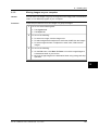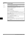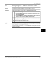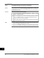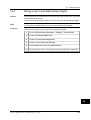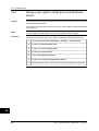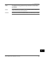
1
nual –
User’s manual
User’s manual –
Benutzerhandbuch – Manual del usuario – Manuel de l’utilisateur –
Manuale dell’utente – Manual
do utilizador – Felhas-
Benutzerhandbuch – Manual del usuario – Manuel de l’utilisateur – Manuale dell’utente – Manual do utilizador – Felhasználói kézikönyv – Käyttäjän opas – Betjeningsználói kézikönyv – Käyttäjän opas –
Betjeningsvejledning – Brukerveiledning – Instrukcja obsługi – Bruksanvisning – Kullanım
dning – Brukerveiledning – Instrukcja obsługi – Bruksanvisning – Kullanım Kılavuzu – Uživatelská příručka – Gebruikershandleiding
Kılavuzu – Uživatelská příručka – Gebruikershandleiding
ThermaCAM™ QuickReport
Program version 1.1
Publ. No.
Revision
Language
Issue date
1558629
a232
English (EN)
July 6, 2007
Notice to user
1
Quick Start Guide
2
Workflow
3
Installation
4
Supported file formats
5
Window elements & toolbar buttons
6
Connecting the camera
7
Handling files
8
Viewing images
9
Analyzing images
10
Adding & editing image descriptions
11
Editing text comments
12
Creating a report
13
Troubleshooting
14
About FLIR Systems
15
Index
16
ThermaCAM™
QuickReport
User’s manual
Publ. No. 1558629 Rev. a232 – ENGLISH (EN) – July 6, 2007
Legal disclaimer
All products manufactured by FLIR Systems are warranted against defective materials and workmanship for a period of one (1) year from the
delivery date of the original purchase, provided such products have been under normal storage, use and service, and in accordance with
FLIR Systems instruction.
All products not manufactured by FLIR Systems included in systems delivered by FLIR Systems to the original purchaser carry the warranty,
if any, of the particular supplier only and FLIR Systems has no responsibility whatsoever for such products.
The warranty extends only to the original purchaser and is not transferable. It is not applicable to any product which has been subjected to
misuse, neglect, accident or abnormal conditions of operation. Expendable parts are excluded from the warranty.
In the case of a defect in a product covered by this warranty the product must not be further used in order to prevent additional damage. The
purchaser shall promptly report any defect to FLIR Systems or this warranty will not apply.
FLIR Systems will, at its option, repair or replace any such defective product free of charge if, upon inspection, it proves to be defective in
material or workmanship and provided that it is returned to FLIR Systems within the said one-year period.
FLIR Systems has no other obligation or liability for defects than those set forth above.
No other warranty is expressed or implied. FLIR Systems specifically disclaims the implied warranties of merchantability and fitness for a
particular purpose.
FLIR Systems shall not be liable for any direct, indirect, special, incidental or consequential loss or damage, whether based on contract, tort
or any other legal theory.
Copyright
© FLIR Systems, 2007. All rights reserved worldwide. No parts of the software including source code may be reproduced, transmitted, transcribed
or translated into any language or computer language in any form or by any means, electronic, magnetic, optical, manual or otherwise,
without the prior written permission of FLIR Systems.
This manual must not, in whole or part, be copied, photocopied, reproduced, translated or transmitted to any electronic medium or machine
readable form without prior consent, in writing, from FLIR Systems.
Names and marks appearing on the products herein are either registered trademarks or trademarks of FLIR Systems and/or its subsidiaries.
All other trademarks, trade names or company names referenced herein are used for identification only and are the property of their respective
owners.
Quality assurance
The Quality Management System under which these products are developed and manufactured has been certified in accordance with the
ISO 9001 standard.
FLIR Systems is committed to a policy of continuous development; therefore we reserve the right to make changes and improvements on
any of the products described in this manual without prior notice.
Patents
This product is protected by patents, design patents, patents pending, or design patents pending.
viii
Publ. No. 1558629 Rev. a232 – ENGLISH (EN) – July 6, 2007
Table of contents
1
Notice to user ..................................................................................................................................
1
2
Quick Start Guide ...........................................................................................................................
3
3
Workflow ..........................................................................................................................................
4
4
Installation ....................................................................................................................................... 7
4.1
System requirements ........................................................................................................... 7
4.2
Installation of ThermaCAM™ QuickReport ........................................................................... 9
4.2.1
Windows® XP installation .................................................................................... 9
4.2.2
Windows® Vista installation ................................................................................. 10
4.3
Installation of USB drivers .................................................................................................... 11
4.4
Updating the program .......................................................................................................... 12
5
Supported file formats ................................................................................................................... 13
6
Window elements & toolbar buttons ............................................................................................
6.1
Window elements: The Organize tab ...................................................................................
6.2
Window elements: The Analyze tab .....................................................................................
6.3
Window elements: The Report tab .......................................................................................
6.4
Toolbar buttons (on the Analyze tab) ...................................................................................
7
Connecting the camera .................................................................................................................. 21
8
Handling files ..................................................................................................................................
8.1
Moving images .....................................................................................................................
8.1.1
Moving images from your camera to your computer ..........................................
8.1.2
Moving images on your computer .......................................................................
8.2
Copying images ...................................................................................................................
8.3
Saving images to a different destination folder ....................................................................
8.4
Cutting & pasting images .....................................................................................................
8.5
Deleting images ....................................................................................................................
8.6
Renaming images .................................................................................................................
8.7
Printing images .....................................................................................................................
8.8
Sending images by e-mail (Microsoft® Outlook only) ........................................................
8.9
Sending images to ThermaCAM™ Reporter ........................................................................
23
23
23
25
26
27
28
29
30
31
32
33
9
Viewing images ...............................................................................................................................
9.1
Changing view settings ........................................................................................................
9.2
Changing zoom factor ..........................................................................................................
9.3
Rotating images ....................................................................................................................
9.4
Changing palette ..................................................................................................................
35
35
36
37
38
10 Analyzing images ...........................................................................................................................
10.1 Using the flying spot meter tool ...........................................................................................
10.2 Creating a spot meter ...........................................................................................................
10.3 Creating a line .......................................................................................................................
10.4 Creating an area ...................................................................................................................
10.5 Isotherms & building alarms ................................................................................................
10.5.1 Creating an isotherm ............................................................................................
10.5.2 About building alarms ...........................................................................................
39
40
41
42
43
44
44
45
Publ. No. 1558629 Rev. a232 – ENGLISH (EN) – July 6, 2007
ix
15
15
16
17
18
10.6
10.7
10.8
10.9
10.10
10.11
10.12
Changing isotherm levels .....................................................................................................
Moving a spot meter, area, or a line .....................................................................................
Deleting a spot meter, area, or a line ...................................................................................
Deleting an isotherm or a building alarm .............................................................................
Changing temperature levels ...............................................................................................
Changing object parameters ................................................................................................
Auto-adjusting an image ......................................................................................................
46
47
48
49
50
51
52
11 Adding & editing image descriptions ........................................................................................... 53
12 Editing text comments ................................................................................................................... 55
13 Creating a report ............................................................................................................................. 56
14 Troubleshooting ..............................................................................................................................
14.1 Ensuring that the camera has the correct software version ................................................
14.2 Restarting the camera ..........................................................................................................
14.3 Troubleshooting connection problems ................................................................................
14.4 Giving a user Local Administrator Rights .............................................................................
14.5 Giving a user rights to install and uninstall device drivers ...................................................
14.6 Troubleshooting password-protected screensaver problems .............................................
59
60
61
62
63
64
65
15 About FLIR Systems .......................................................................................................................
15.1 More than just an infrared camera .......................................................................................
15.2 Sharing our knowledge ........................................................................................................
15.3 Supporting our customers ...................................................................................................
15.4 A few images from our facilities ...........................................................................................
67
68
68
68
69
Index ................................................................................................................................................ 71
x
Publ. No. 1558629 Rev. a232 – ENGLISH (EN) – July 6, 2007
1
Notice to user
Typographical
conventions
This manual uses the following typographical conventions:
■
■
■
■
Comments and
questions
1
Semibold is used for menu names, menu commands and labels, and buttons in
dialog boxes.
Italic is used for important information.
Monospace is used for code samples.
UPPER CASE is used for names on keys and buttons.
Make a report of errors that you find, as well as your suggestions for new revisions.
Send an e-mail to:
[email protected]
Technical support
For technical support, visit:
http://flir.custhelp.com
To submit a question to the technical support team, you must be a registered user.
It only takes a few minutes to register online. If you only want to search the knowledgebase for existing questions and answers, you do not need to be a registered
user.
When you want to submit a question, make sure that you have the following information to hand:
■
■
■
■
■
■
User-to-user
forums
The camera model
The camera serial number
The communication protocol, or method, between the camera and your PC (for
example, Ethernet, USB, or FireWire)
Operating system on your PC
Microsoft® Office version
Full name, publication number, and revision number of the manual
Exchange ideas, problems, and infrared solutions with fellow thermographers around
the world in our user-to-user forums. To go to the forums, visit:
http://www.infraredtraining.com/community/boards/
Software updates
FLIR Systems regularly issues software upgrades and service releases on the support
pages of the company website:
http://www.flirthermography.com
To find the latest upgrades and service releases, make that sure you select USA in
the Select country box in the top right corner of the page.
Training
To read about infrared training, visit:
http://www.infraredtraining.com
Publ. No. 1558629 Rev. a232 – ENGLISH (EN) – July 6, 2007
1
1 – Notice to user
1
Additional license
information
2
This software is sold under a single user license. This license permits the user to install
and use the software on any compatible computer provided the software is used on
only one computer at a time. One (1) back-up copy of the software may also be made
for archive purposes.
Publ. No. 1558629 Rev. a232 – ENGLISH (EN) – July 6, 2007
2
Quick Start Guide
Procedure
Follow this procedure to get started right away:
1
2
Install ThermaCAM™ QuickReport on your computer.
For more information, see section 4 – Installation on page 7.
2
Connect your camera to the computer, using a USB cable.
For more information, see section 7 – Connecting the camera on page 21.
3
Start ThermaCAM™ QuickReport.
4
On the Organize tab, click Transfer images and follow the on-screen instructions to move the images from the camera to a destination folder on
your computer.
For more information, see section 8 – Handling files on page 23.
5
In the folder pane, go to the destination folder.
6
On the Analyze tab, add measurement tools, create or edit image descriptions, edit text comments, listen to voice comments, change object parameters, etc.
For more information, see section 10 – Analyzing images on page 39.
7
On the Report tab, select a report template and move the images that you
want to include in the report to the report pane by using a drag-and-drop
operation.
For more information, see section 13 – Creating a report on page 56.
8
Create the report.
Publ. No. 1558629 Rev. a232 – ENGLISH (EN) – July 6, 2007
3
3
3
Workflow
General
When you carry out an infrared inspection you follow a typical workflow. This section
gives an example of an infrared inspection workflow.
Figure
10548003;a8
Explanation
This table gives an explanation to the figure above:
1
Use your camera to take your infrared images and/or digital photos.
2
Do one of the following:
■
■
■
Method 1: Move the images using a USB cable.
Method 2: Move the images using a CompactFlash card.
Method 3: Move the images using an SD Memory Card.
For more information, see the following sections:
■
■
4
Section 7 – Connecting the camera on page 21
Section 8.1 – Moving images on page 23
Publ. No. 1558629 Rev. a232 – ENGLISH (EN) – July 6, 2007
3 – Workflow
3
In ThermaCAM™ QuickReport, do one or more of the following:
■
■
■
■
■
Change how the images are viewed
Handle files
Analyze images
Add and edit image descriptions
Edit text comments
3
For more information, see the following sections:
■
■
■
■
4
Section 9 – Viewing images on page 35
Section 8 – Handling files on page 23
Section 10 – Analyzing images on page 39
Section 11 – Adding & editing image descriptions on page 53
Do one of the following to create an infrared report:
■
■
■
■
Using a drag-and-drop operation, organize your report on the Report
tab, and then click Create report.
Using a drag-and-drop operation, move images from ThermaCAM™
QuickReport into Microsoft® Word, add your own comments and descriptions and use Microsoft® Word to create a report.
Using a drag-and-drop operation, move images from ThermaCAM™
QuickReport into ThermaCAM™ Reporter (an add-on to Microsoft®
Word) and use ThermaCAM™ Reporter to create the report.
On the File menu, select Create ThermaCAM report using this template
to send selected images to ThermaCAM™ Reporter.
For more information, see section 13 – Creating a report on page 56.
Publ. No. 1558629 Rev. a232 – ENGLISH (EN) – July 6, 2007
5
3 – Workflow
3
INTENTIONALLY LEFT BLANK
6
Publ. No. 1558629 Rev. a232 – ENGLISH (EN) – July 6, 2007
4
Installation
4.1
System requirements
Operating system
ThermaCAM™ QuickReport supports USB communication for the following PC operating systems:
■
■
Hardware
Microsoft® Windows® XP with Service Pack 2 (SP-2), or later
Windows® Vista®
4
Microsoft® Windows® XP:
■
■
■
■
■
■
■
Personal computer with an Intel® 800 MHz Pentium processor, or an AMD Opteron,
AMD Athlon 64, or AMD Athlon XP processor
512 MB of RAM, or greater
20 GB of available hard disk space
CD-ROM or DVD-ROM drive
Super VGA (1024 × 768) or higher-resolution monitor
Internet access required for web updates
Keyboard and Microsoft® mouse, or a compatible pointing device
Microsoft® Windows® Vista:
■
■
■
■
■
Personal computer with a 1 GHz 32-bit (x86) processor
1 GB of RAM, or greater
40 GB hard disk, with at least 15 GB available hard disk space
DVD-ROM drive
Support for DirectX 9 graphics with:
■
■
■
■
■
■
■
■
Camera system
WDDM Driver
128 MB of graphics memory (minimum)
Pixel Shader 2.0 in hardware
32 bits per pixel
Super VGA (1024 × 768) or higher-resolution monitor
Internet access (fees may apply)
Audio output
Keyboard and Microsoft® mouse, or a compatible pointing device
If you intend to use ThermaCAM™ QuickReport with one of the following cameras,
you must ensure that your camera software version is supported:
■
■
■
■
B series cameras (except BCAM and B640)
E series cameras
P series cameras (except P640)
S series cameras
For more information about supported camera software versions, see section 14.1
– Ensuring that the camera has the correct software version on page 60.
Publ. No. 1558629 Rev. a232 – ENGLISH (EN) – July 6, 2007
7
4 – Installation
Compatibility with
software from FLIR
Systems
Sending infrared images and digital photos to ThermaCAM™ Reporter requires one
of the following software versions:
■
■
■
■
NOTE
■
■
■
4
8
ThermaCAM™ Reporter 8, or later
ThermaCAM™ Reporter 8 Professional, or later
ThermaCAM™ Reporter 7 Basic, with Service Release 4 (SR-4)
ThermaCAM™ Reporter 7 Professional, with Service Release 4 (SR-4)
Microsoft® Windows® XP 64-bit is not supported.
Microsoft® Windows® Vista 64-bit is not supported.
Actual requirements and product functionality may vary based on your system
configuration.
Publ. No. 1558629 Rev. a232 – ENGLISH (EN) – July 6, 2007
4 – Installation
4.2
Installation of ThermaCAM™ QuickReport
4.2.1
Windows® XP installation
NOTE
Before you install ThermaCAM™ QuickReport, do the following:
1 Close all programs.
2 Uninstall any previous versions of ThermaCAM™ QuickReport and ThermaCAM™
QuickView.
3 Uninstall any drivers and language packs related to these programs.
Procedure
4
Follow this procedure to install ThermaCAM™ QuickReport:
1
Insert the ThermaCAM™ QuickReport installation CD into the CD-ROM
drive. The installation should start automatically.
If the installation does not start automatically, follow this procedure:
1
2
3
4
2
Double-click My Computer on Desktop.
Right-click the CD-ROM drive and click Explore.
Double-click SETUP.EXE.
Go to Step 2 below.
ThermaCAM™ QuickReport requires some prerequisites.
If they are not already installed on your computer, click OK when asked if
you want to install the software.
3
ThermaCAM™ QuickReport requires Microsoft® .NET Framework 2.0.
If this software is not already installed on your computer, click OK when
asked if you want to install the software.
Installation of Microsoft® .NET Framework 2.0 can take several minutes.
4
In the ThermaCAM™ QuickReport installation wizard dialog box, click Next.
5
In the license agreement dialog box, carefully read and accept the license
agreement and click Next.
6
In the customer information dialog box, enter your customer details and
click Next.
7
Click Install.
8
Click Finish.
9
If you are asked to restart your computer, do so.
Publ. No. 1558629 Rev. a232 – ENGLISH (EN) – July 6, 2007
9
4 – Installation
4.2.2
Windows® Vista installation
General
Before you install ThermaCAM™ QuickReport, close all programs.
Procedure
Follow this procedure to install ThermaCAM™ QuickReport:
4
10
1
Insert the ThermaCAM™ QuickReport installation CD into the CD-ROM
drive. The installation should start automatically.
2
In the Autoplay dialog box, click Run setup.exe (Published by FLIR Systems).
3
In the User Account Control dialog box, confirm that you want to install
ThermaCAM™ QuickReport.
4
In the language dialog box, select the language that you want to use and
install for ThermaCAM™ QuickReport.
5
In the Welcome to the InstallShield Wizard for ThermaCAM™ QuickReport
dialog box, click Next.
6
In the License Agreement dialog box, carefully read and accept the license
agreement and click Next.
7
In the Customer Information dialog box, enter your customer details and
click Next.
8
In the Ready to Install the Program dialog box, click Install.
9
Click Finish. The installation is now completed. If you are asked to restart
your computer, do so.
Publ. No. 1558629 Rev. a232 – ENGLISH (EN) – July 6, 2007
4 – Installation
4.3
Installation of USB drivers
NOTE
If your camera and PC operating system combination is one of the following, you
may need to install additional drivers:
■
■
Procedure
Windows® XP and an E/P/S series camera
Windows® Vista and an E/P/S series camera
Follow this procedure to install additional drivers:
1
Start the camera.
2
Connect the camera to the PC.
3
When the computer has detected the camera, follow the on-screen instructions to install USB drivers.
Publ. No. 1558629 Rev. a232 – ENGLISH (EN) – July 6, 2007
4
11
4 – Installation
4.4
Updating the program
General
You can update the program in two different ways:
■
■
Procedure
4
Download and install program updates (new point releases, bug fixes, patches,
etc.).
Download and install new or revised language packs (user’s manuals, help files,
etc.).
Follow this procedure to update your program:
1
On Windows® Start menu, click Programs.
2
In the list of programs, go to FLIR Systems and follow this procedure (in
this order):
1 On the ThermaCAM™ QuickReport submenu, click Check for updates.
2 On the ThermaCAM™ QuickReport submenu, click Check for languages.
3
12
Follow the on-screen instructions to download and install the program updates and/or language packs.
Publ. No. 1558629 Rev. a232 – ENGLISH (EN) – July 6, 2007
5
Supported file formats
General
ThermaCAM™ QuickReport supports several radiometric and non-radiometric file
formats.
Radiometric file
formats
ThermaCAM™ QuickReport supports the following radiometric file formats:
■
■
Non-radiometric
file formats
ThermaCAM™ QuickReport supports the following non-radiometric file formats:
■
■
NOTE
ThermaCAM™ radiometric *.jpg
ThermaCAM™ radiometric *.img
*.jpg
*.bmp
5
Radiometric *.jpg images that are merged from an infrared image and a digital photo
will be correctly displayed in ThermaCAM™ QuickReport. However, the degree of
merging can not be changed in this program. Furthermore, temperature analysis can
not be carried out on such images.
Publ. No. 1558629 Rev. a232 – ENGLISH (EN) – July 6, 2007
13
5 – Supported file formats
5
INTENTIONALLY LEFT BLANK
14
Publ. No. 1558629 Rev. a232 – ENGLISH (EN) – July 6, 2007
6
Window elements & toolbar
buttons
6.1
Window elements: The Organize tab
Figure
10756003;a1
6
Explanation
This table gives an explanation to the figure above:
1
Folder pane
2
Buttons (from left to right):
■
■
■
Transfer images
Print selected images
Thumbnail size
3
Menu bar
4
Tabs (from left to right):
■
■
■
Organize
Analyze
Report
5
Minimize, Maximize, and Close buttons
6
Image pane
Publ. No. 1558629 Rev. a232 – ENGLISH (EN) – July 6, 2007
15
6 – Window elements & toolbar buttons
6.2
Window elements: The Analyze tab
Figure
10756103;a2
Explanation
This table gives an explanation to the figure above:
6
1
Infrared image with measurement tools
2
Image toolbar
For more information, see section 6.4 – Toolbar buttons (on the Analyze
tab) on page 18.
16
3
Image information from the camera
4
Image description text box. You can edit an existing image description in
this text box, or enter a new image description.
5
Text comments tab and Object parameters tab. You can edit both text
comments and object parameters.
6
Measurement result table
Publ. No. 1558629 Rev. a232 – ENGLISH (EN) – July 6, 2007
6 – Window elements & toolbar buttons
6.3
Figure
Window elements: The Report tab
10756203;a1
6
Explanation
This table gives an explanation to the figure above:
1
Image pane
2
You use these button to configure your inspection report (left to right):
■
■
■
■
■
■
3
Report template: To select which report template you want to use
Report information: To change logotype, enter thermographer and
customer contact information, etc.
Add images to report: To add all or selected images to the report
Move report page: To move a selected report page to another position
in the report
Delete report page: To delete a selected report page from the report
Create report: To create the report as a Adobe® PDF file
Report preview pane
Publ. No. 1558629 Rev. a232 – ENGLISH (EN) – July 6, 2007
17
6 – Window elements & toolbar buttons
6.4
Toolbar buttons
Toolbar buttons (on the Analyze tab)
Save tool
You use this tool to save changes that you have made within an image.
Select tool
You use this tool when you want to move spots, areas, lines, and isotherm
levels within an image. You also use the tool to deselect menu commands
on the image toolbar menus.
Flying spot meter tool
You use this tool to create a flying spot meter. When you move the flying
spot meter over the image area, the temperature will be displayed at the
location of the spot meter.
Spot meter tool
6
You use this tool to create a spot meter that you can put anywhere on the
image. The spot meter and the temperature it displays will be stored
within the image when you save it.
To move the spot meter, use the Select tool.
Area tool
You use this tool to click-and-drag within the image to create an area. The
minimum and maximum temperature in the area will be displayed in the
measurement result table.
To move the area, use the Select tool.
Line tool
You use this tool to create a line within the image. The minimum and
maximum temperature along the line will be displayed in the measurement
result table.
To move the line, use the Select tool.
Isotherm tool
You use this tool to create isotherms, i.e., to assign specific colors to
specific temperature ranges. You also use this tool to work with building
alarms.
To move the isotherm levels in the temperature scale, use the Select tool.
Delete tool
You use this tool to delete one or several selected measurement tools.
Palette tool
You use this tool to change the color palette within an image.
18
Publ. No. 1558629 Rev. a232 – ENGLISH (EN) – July 6, 2007
6 – Window elements & toolbar buttons
Auto-adjust tool
You use this tool to auto-adjust an image for best brightness and contrast.
Zoom tool
You use this tool to change the zoom factor within an image.
Rotate counter-clockwise tool
You use this tool to rotate an image counter-clockwise in 90° increments.
Rotate clockwise tool
You use this tool to rotate an image clockwise in 90° increments.
Image navigation tool, #1
You use this tool to go to the first image in the work folder. By using the
slider, you can quickly browse through the images in a work folder.
Image navigation tool, #2
You use this tool to go to the previous image in the work folder. By using
the slider, you can quickly browse through the images in a work folder.
Image navigation tool, #3
You use this tool to go to the next image in the work folder. By using the
slider, you can quickly browse through the images in a work folder.
Image navigation tool, #4
You use this tool to go to the last image in the work folder. By using the
slider, you can quickly browse through the images in a work folder.
Voice comment tool.
You use this tool to listen to voice comments associated with an image.
Export to Microsoft® Excel tool
You use this tool to export pixel temperature values to Microsoft® Excel.
You can then perform a variety of calculations on the pixel values.
Publ. No. 1558629 Rev. a232 – ENGLISH (EN) – July 6, 2007
19
6
6 – Window elements & toolbar buttons
6
INTENTIONALLY LEFT BLANK
20
Publ. No. 1558629 Rev. a232 – ENGLISH (EN) – July 6, 2007
7
Connecting the camera
General
If your camera does not have a CompactFlash card or SD Memory Card, you must
connect the camera to a computer to move the images to the computer.
Procedure
Follow this procedure to connect the camera to a computer:
1
Do one of the following:
■
■
If your camera is an InfraCAM/InfraCAM SD, a BCAM/BCAM SD, or a
B640/P640/SC640 camera, select Standard in the camera program (USB
cable → Standard).
If you have another camera, go to the second bullet in Step 2 below.
2
Connect a USB cable to the USB connector on the connector panel of the
camera.
3
Connect the other end of the USB cable to its connector on the rear connector panel of a desktop or laptop computer.
4
When you have connected the camera the computer, go to section 8.1 –
Moving images on page 23 for further instructions.
Publ. No. 1558629 Rev. a232 – ENGLISH (EN) – July 6, 2007
21
7
7 – Connecting the camera
7
INTENTIONALLY LEFT BLANK
22
Publ. No. 1558629 Rev. a232 – ENGLISH (EN) – July 6, 2007
8
Handling files
8.1
Moving images
8.1.1
Moving images from your camera to your computer
General
Depending on camera model, you can use three different methods to move images
from your camera to your computer:
■
■
■
Method 1
Method 1: Move the images using a USB cable.
Method 2: Move the images using a CompactFlash card.
Method 3: Move the images using an SD Memory Card.
Follow this procedure to move images from your camera to your computer using a
USB cable:
1
To start ThermaCAM™ QuickReport and display the Transfer images dialog
box, connect your camera to the computer (see section 7 – Connecting the
camera on page 21).
If the Transfer images dialog box does not appear automatically, start
ThermaCAM™ QuickReport and click Transfer images on the Organize
tab. This will display the dialog box.
2
In the Transfer images dialog box, click one of these buttons:
■
■
NOTE
8
Copy all images from the camera
Move all images from the camera
3
To select a different destination folder, click Browse.
4
To move the images, click OK.
Depending on the camera model, the images may be saved in a subfolder instead
of the specified folder itself, e.g., in C:\2007-01-23\images\dirA\ instead of C:\200701-23\.
Publ. No. 1558629 Rev. a232 – ENGLISH (EN) – July 6, 2007
23
8 – Handling files
Method 2
Follow this procedure to move images from your camera to your computer using a
CompactFlash card:
1
Remove the CompactFlash card from your camera and insert it into a
CompactFlash card reader that is connected to your computer.
2
In the folder pane of ThermaCAM™ QuickReport, go to the disk drive for
the CompactFlash card reader.
3
Do one of the following:
■
■
Method 3
8
Follow this procedure to move images from your camera to your computer using a
SD Memory Card:
1
Remove the SD Memory Card from your camera and insert it into a SD
Memory Card reader that is connected to your computer.
2
In the folder pane of ThermaCAM™ QuickReport, go to the disk drive for
the SD Memory Card reader.
3
Do one of the following:
■
■
24
On the Edit menu, click Move To Folder to move the image/images to
a destination folder of your choice.
Move the images to the destination folder using a drag-and-drop operation.
On the Edit menu, click Move To Folder to move the image/images to
a destination folder of your choice.
Move the images to the destination folder using a drag-and-drop operation.
Publ. No. 1558629 Rev. a232 – ENGLISH (EN) – July 6, 2007
8 – Handling files
8.1.2
Moving images on your computer
General
You can move one image or a group of images from the image pane to a destination
folder, or to a different program on your computer.
Procedure
Follow this procedure to move one image or a group of images:
1
Go to one of the following tabs:
■
■
2
Do one of the following:
■
■
■
3
The Organize tab
The Report tab
To select one image, click the image once.
To select images that are adjacent to each other, SHIFT-click the images.
To select images that are not adjacent to each other, CTRL-click the
images.
Do one of the following:
■
■
On the Edit menu, click Move To Folder to move the image/images to
a destination folder of your choice.
Move the image/images to the destination folder using a drag-and-drop
operation.
8
Publ. No. 1558629 Rev. a232 – ENGLISH (EN) – July 6, 2007
25
8 – Handling files
8.2
Copying images
General
You can copy one image or a group of images from the image pane to a destination
folder, or to a different program on your computer.
Procedure
Follow this procedure to copy one image or a group of images:
1
Go to one of the following tabs:
■
■
2
Do one of the following:
■
■
■
3
■
■
4
On the Edit menu, click Copy To Folder to copy the image/images to a
destination folder of your choice.
Right-click the image/images and click Copy.
Press CTRL + C.
Do one of the following:
■
■
26
To select one image, click the image once.
To select images that are adjacent to each other, SHIFT-click the images.
To select images that are not adjacent to each other, CTRL-click the
images.
Do one of the following:
■
8
The Organize tab
The Report tab
Select a destination folder or a different program and press CTRL + V.
Select a destination folder or a different program and click Paste on the
Edit menu.
Publ. No. 1558629 Rev. a232 – ENGLISH (EN) – July 6, 2007
8 – Handling files
8.3
Saving images to a different destination folder
General
You can save an image to a different destination folder on your PC.
Procedure
Follow this procedure to save an image to a different destination folder:
1
Do one of the following:
■
■
NOTE
Go to the Organize tab and select the image you want to save to a different destination folder.
Go to the Analyze tab and use the image navigation slider to select the
image you want to save to a different destination folder.
2
When you are on the Analyze tab, click Save As on the File menu and select
a destination folder of your choice.
3
Save the image to this destination folder.
When you go back to the program after you have saved the image, it is the old image
that is displayed—not the image you just saved.
To find the image you just saved, go to the Organize tab and navigate to the folder
using the folder pane.
8
Publ. No. 1558629 Rev. a232 – ENGLISH (EN) – July 6, 2007
27
8 – Handling files
8.4
Cutting & pasting images
General
You can cut & paste one image or a group of images to a destination folder, or to a
different program.
Procedure
Follow this procedure to cut & paste one image or a group of images:
1
Go to one of the following tabs:
■
■
2
Do one of the following:
■
■
■
3
■
■
28
Right-click the image/images and click Cut.
Press CTRL + X.
In the destination folder, or the target application, do one of the following:
■
8
To select one image, click the image once.
To select images that are adjacent to each other, SHIFT-click the images.
To select images that are not adjacent to each other, CTRL-click the
images.
Do one of the following:
■
4
The Organize tab
The Report tab
Right-click and click Paste.
Press CTRL + V.
Publ. No. 1558629 Rev. a232 – ENGLISH (EN) – July 6, 2007
8 – Handling files
8.5
Deleting images
General
You can delete one image or a group of images.
Procedure
Follow this procedure to delete one image or a group of images:
1
Go to one of the following tabs:
■
■
2
Do one of the following:
■
■
■
3
To select one image, click the image once.
To select images that are adjacent to each other, SHIFT-click the images.
To select images that are not adjacent to each other, CTRL-click the
images.
Do one of the following:
■
■
NOTE
The Organize tab
The Report tab
Press DELETE.
On the File menu, click Delete.
When you delete an image or a group of images, you can still restore them from the
computer’s Recycle Bin.
8
Publ. No. 1558629 Rev. a232 – ENGLISH (EN) – July 6, 2007
29
8 – Handling files
8.6
Renaming images
General
You can rename an image.
Procedure
Follow this procedure to rename an image:
1
Go to one of the following tabs:
■
■
The Organize tab
The Report tab
2
To select an image, click the image one time.
3
Right-click the image and click Rename.
4
Type the new name for the image and press ENTER.
8
30
Publ. No. 1558629 Rev. a232 – ENGLISH (EN) – July 6, 2007
8 – Handling files
8.7
Printing images
General
You can print one image or a group of images on a local or network printer.
Procedure
Follow this procedure to print one image or a group of images:
1
Go to one of the following tabs:
■
■
■
2
Do one of the following:
■
■
■
3
The Organize tab
The Analyze tab
The Report tab
To select one image, click the image once.
To select images that are adjacent to each other, SHIFT-click the images.
To select images that are not adjacent to each other, CTRL-click the
images.
Do one of the following:
■
If you are on the Organize tab, do one of the following:
■
■
■
■
■
If you are on the Analyze tab, select Print on the File menu.
If you are on the Report tab, do one of the following:
■
■
4
Right-click the image/images and click Print.
Click Print selected images.
On the File menu, select Print.
8
Right-click the image/images and click Print.
On the File menu, select Print.
In the Print dialog box, make the necessary changes and click OK.
Publ. No. 1558629 Rev. a232 – ENGLISH (EN) – July 6, 2007
31
8 – Handling files
8.8
Sending images by e-mail (Microsoft® Outlook only)
General
You can send one image or a group of images by e-mail.
Procedure
Follow this procedure to send one image or a group of images by e-mail:
1
Go to one of the following tabs:
■
■
2
Do one of the following:
■
■
■
3
The Organize tab
The Report tab
To select one image, click the image once.
To select images that are adjacent to each other, SHIFT-click the images.
To select images that are not adjacent to each other, CTRL-click the
images.
Do one of the following:
■
■
Right-click the image/images and click Send To → Mail Recipient.
On the File menu, click Send To Mail Recipient.
8
32
Publ. No. 1558629 Rev. a232 – ENGLISH (EN) – July 6, 2007
8 – Handling files
8.9
Sending images to ThermaCAM™ Reporter
General
You can send an image or a group of images to ThermaCAM™ Reporter. ThermaCAM™ Reporter is an advanced reporting program for infrared and visual images.
Procedure
Follow this procedure to send one image or a group of images to ThermaCAM™
Reporter:
1
Go to one of the following tabs:
■
■
2
Do one of the following:
■
■
■
3
NOTE
The Organize tab
The Report tab
To select one image, click the image once.
To select images that are adjacent to each other, SHIFT-click the images.
To select images that are not adjacent to each other, CTRL-click the
images.
On the File menu, select Create ThermaCAM report using this template
to send selected images to ThermaCAM™ Reporter.
Sending infrared images and digital photos to ThermaCAM™ Reporter requires one
of the following software versions:
■
■
■
■
ThermaCAM™ Reporter 8, or later
ThermaCAM™ Reporter 8 Professional, or later
ThermaCAM™ Reporter 7 Basic, with Service Release 4 (SR-4)
ThermaCAM™ Reporter 7 Professional, with Service Release 4 (SR-4)
Publ. No. 1558629 Rev. a232 – ENGLISH (EN) – July 6, 2007
8
33
8 – Handling files
INTENTIONALLY LEFT BLANK
8
34
Publ. No. 1558629 Rev. a232 – ENGLISH (EN) – July 6, 2007
9
Viewing images
9.1
Changing view settings
General
On the Organize tab and the Report tab you can change the size of image thumbnails.
Procedure
Follow this procedure to change the size of image thumbnails:
1
Go to one of the following tabs:
■
■
2
The Organize tab
The Report tab
Move the Thumbnail size slider to the left (smaller thumbnails) or to the
right (larger thumbnails).
9
Publ. No. 1558629 Rev. a232 – ENGLISH (EN) – July 6, 2007
35
9 – Viewing images
9.2
Changing zoom factor
General
You can change zoom factor for an image.
Procedure
Follow this procedure to change zoom factor for an image:
1
Do one of the following:
■
■
2
Go to the Organize tab and select the image for which you want to
change zoom factor.
Go to the Analyze tab and use the image navigation slider to select the
image for which you want to change zoom factor.
On the image toolbar on the Analyze tab, click the zoom factor on the Zoom
menu.
NOTE
To reset the zoom factor to 1×, press the space bar on your keyboard.
9
36
Publ. No. 1558629 Rev. a232 – ENGLISH (EN) – July 6, 2007
9 – Viewing images
9.3
Rotating images
General
You can rotate an image counter-clockwise or clockwise in 90° increments.
Procedure
Follow this procedure to rotate an image:
1
Do one of the following:
■
■
2
Go to the Organize tab and select the image you want to rotate.
Go to the Analyze tab and use the image navigation slider to select the
image you want to rotate.
On the Analyze tab, do one of the following:
■
To rotate the image counter-clockwise, click the
■
To rotate the image clock-wise, click the
toolbar button.
toolbar button.
9
Publ. No. 1558629 Rev. a232 – ENGLISH (EN) – July 6, 2007
37
9 – Viewing images
9.4
Changing palette
General
You can change the palette that the camera uses to display the different temperatures
within the image. A different palette can make it easier to make an analysis of the
image.
Procedure
Follow this procedure to change the palette:
1
Do one of the following:
■
■
Go to the Organize tab and select the image for which you want to
change the palette.
Go to the Analyze tab and use the image navigation slider to select the
image for which you want to change the palette.
2
On the Analyze tab, click the
NOTE
■
■
toolbar button to select a new palette.
In some camera models, Palette is called Color.
Radiometric *.jpg images that are merged from an infrared image and a digital
photo will be correctly displayed in ThermaCAM™ QuickReport. However, the
degree of merging can not be changed in this program. Furthermore, temperature
analysis can not be carried out on such images.
9
38
Publ. No. 1558629 Rev. a232 – ENGLISH (EN) – July 6, 2007
10
Analyzing images
General
Do one or more of the following steps to analyze your images:
■
■
■
■
■
■
■
■
■
■
■
■
SEE ALSO
Use the flying spot meter tool.
Create a spot meter.
Create a line.
Create a measurement area.
Create an isotherm.
Move a spot or an area.
Delete a spot or an area.
Delete an isotherm.
Change isotherm levels.
Change temperature levels.
Change object parameters.
Auto-adjust the image.
For more information, see these sections:
■
■
■
■
■
■
■
■
■
■
■
■
Section 10.1 – Using the flying spot meter tool on page 40
Section 10.2 – Creating a spot meter on page 41
Section 10.3 – Creating a line on page 42
Section 10.4 – Creating an area on page 43
Section 10.5 – Isotherms & building alarms on page 44
Section 10.7 – Moving a spot meter, area, or a line on page 47
Section 10.8 – Deleting a spot meter, area, or a line on page 48
Section 10.9 – Deleting an isotherm or a building alarm on page 49
Section 10.6 – Changing isotherm levels on page 46
Section 10.10 – Changing temperature levels on page 50
Section 10.11 – Changing object parameters on page 51
Section 10.12 – Auto-adjusting an image on page 52
Publ. No. 1558629 Rev. a232 – ENGLISH (EN) – July 6, 2007
10
39
10 – Analyzing images
10.1
Using the flying spot meter tool
Procedure
Follow this procedure to use the flying spot meter tool to see the temperature:
1
On the Organize tab, double-click an image.
2
On the image toolbar on the Analyze tab, click the
3
toolbar button.
To display the temperature, move the flying spot meter tool to any position
on the image. The temperature will be displayed at the position of the flying
spot meter tool.
10
40
Publ. No. 1558629 Rev. a232 – ENGLISH (EN) – July 6, 2007
10 – Analyzing images
10.2
Creating a spot meter
Procedure
Follow this procedure to create a spot meter:
1
On the Organize tab, double-click an image.
2
On the image toolbar on the Analyze tab, click the
3
toolbar button.
To create a spot meter, click in the image at the position where you want
the spot meter to appear. The temperature will be displayed in the result
table.
10
Publ. No. 1558629 Rev. a232 – ENGLISH (EN) – July 6, 2007
41
10 – Analyzing images
10.3
Creating a line
Procedure
Follow this procedure to create a line:
1
On the Organize tab, double-click an image.
2
On the image toolbar on the Analyze tab, click the
3
toolbar button.
To create a line, click-and-drag within the image. The temperature along
the line will be displayed in the result table.
10
42
Publ. No. 1558629 Rev. a232 – ENGLISH (EN) – July 6, 2007
10 – Analyzing images
10.4
Creating an area
Procedure
Follow this procedure to an create an area:
1
On the Organize tab, double-click an image.
2
On the image toolbar on the Analyze tab, click the
3
toolbar button.
To create an area, click-and-drag within the image. The minimum and
maximum temperature will be displayed in the result table.
10
Publ. No. 1558629 Rev. a232 – ENGLISH (EN) – July 6, 2007
43
10 – Analyzing images
10.5
Isotherms & building alarms
10.5.1
Creating an isotherm
General
You use the isotherm tool to assign a color to specific temperature ranges, and to
work with alarms.
Procedure
Follow this procedure to create an isotherm:
1
On the Organize tab, double-click an image.
2
On the image toolbar on the Analyze tab, select one of the following
isotherm types on the Isotherm and alarm tools
■
■
■
NOTE
menu:
Above
Below
Interval
In some camera models, Isotherm is called Color alarm.
10
44
Publ. No. 1558629 Rev. a232 – ENGLISH (EN) – July 6, 2007
10 – Analyzing images
10.5.2
About building alarms
General
If your camera supports Dewpoint alarm and Insulation alarm, you can work with
these alarms in ThermaCAM™ QuickReport.
About the
Dewpoint alarm
Dewpoint can be regarded as the temperature at which the humidity in a certain
volume of air will condense as liquid water. At this point, the relative humidity is 100%.
When you have set a number of environmental parameters, the Dewpoint alarm can
detect these areas and warn you that there may be a deficiency in the building
structure.
About the
Insulation alarm
The Insulation alarm can detect areas where there may be an insulation deficiency
in the building. It will trigger when the insulation level falls below a preset value of
the energy leakage through the wall.
Different building codes recommend different values, but typical values are 0.6–0.8
for new buildings. Refer to your national building code for recommendations.
About the Alarm
Settings dialog
box
On the Insulation alarm tab you can change one or more of the following alarm parameters:
■
■
■
Outdoor temperature
Indoor temperature
Insulation level
On the Dewpoint alarm tab you can change one or more of the following alarm parameters:
■
■
SEE
Relative humidity
Atmospheric temperature
For more information about these alarm types and alarm parameters, see your
camera manual.
10
Publ. No. 1558629 Rev. a232 – ENGLISH (EN) – July 6, 2007
45
10 – Analyzing images
10.6
Changing isotherm levels
Procedure
Follow this procedure to change isotherm levels:
1
On the Organize tab, double-click an image.
2
On the image toolbar on the Analyze tab, select one of the following
isotherm types on the Isotherm and alarm tools
■
■
■
menu:
Above
Below
Interval
3
On the image toolbar on the Analyze tab, click the
4
NOTE
toolbar button.
To change isotherm levels, click-and-drag the bar in the temperature scale.
In some camera models, Isotherm is called Color alarm.
10
46
Publ. No. 1558629 Rev. a232 – ENGLISH (EN) – July 6, 2007
10 – Analyzing images
10.7
Moving a spot meter, area, or a line
Procedure
Follow this procedure to move a spot meter, area, or a line:
1
On the Organize tab, double-click an image.
2
On the image toolbar on the Analyze tab, click the
toolbar button.
3
Click the spot meter or the area once and hold down the mouse key.
4
To move the spot meter or the area, move the mouse and then release the
mouse button.
10
Publ. No. 1558629 Rev. a232 – ENGLISH (EN) – July 6, 2007
47
10 – Analyzing images
10.8
Deleting a spot meter, area, or a line
Procedure
Follow this procedure to delete a spot meter, area, or a line:
1
On the Organize tab, double-click an image.
2
On the image toolbar on the Analyze tab, click the
toolbar button.
3
Click the spot meter, the area or line once.
4
Do one of the following to delete the spot meter, the area or line:
■
Press DELETE
■
On the image toolbar, click the
toolbar button.
10
48
Publ. No. 1558629 Rev. a232 – ENGLISH (EN) – July 6, 2007
10 – Analyzing images
10.9
Deleting an isotherm or a building alarm
Procedure
Follow this procedure to delete an isotherm or a building alarm:
1
On the Organize tab, double-click an image that has an isotherm.
2
On the image toolbar on the Analyze tab, click the selected isotherm type
or building alarm on the Isotherm and alarm tools
the isotherm or building alarm.
menu. This will delete
10
Publ. No. 1558629 Rev. a232 – ENGLISH (EN) – July 6, 2007
49
10 – Analyzing images
10.10
Changing temperature levels
General
At the bottom of the infrared image you will see two sliders. By dragging these sliders
to the left or to the right you can change the top and bottom levels in the temperature
scale.
Changing the top
level
Follow this procedure to change the top level in the temperature scale:
Changing the
bottom level
Changing both the
top & bottom
levels at the same
time
1
On the Organize tab, double-click an image.
2
In the image on the Analyze tab, drag the right slider right or left to change
the top level in the temperature scale
Follow this procedure to change the bottom level in the temperature scale:
1
On the Organize tab, double-click an image.
2
In the image on the Analyze tab, drag the left slider right or left to change
the bottom level in the temperature scale.
Follow this procedure to change both the top and the bottom levels in the temperature
scale at the same time:
1
On the Organize tab, double-click an image.
2
In the image on the Analyze tab, SHIFT-drag the left or right slider right or
left to change both the top and the bottom levels in the temperature scale
at the same time.
10
50
Publ. No. 1558629 Rev. a232 – ENGLISH (EN) – July 6, 2007
10 – Analyzing images
10.11
Changing object parameters
General
You can change the object parameter values for an image. Object parameters have
an effect on the infrared radiation that the camera measures.
Recommended
values
If you are unsure about the values, the following values are recommended:
Procedure
Atmospheric temperature
+20°C (+69°F)
Distance
1.0 m (3.3 ft.)
Emissivity
0.95
Reflected apparent temperature
+20°C (+69°F)
Relative humidity
50%
Follow this procedure to change object parameters:
1
On the Organize tab, double-click an image.
2
On the Analyze tab, go to the Object parameters tab in the right pane.
3
Type a value in the text box for each object parameter that you want to
change.
4
Click Apply.
10
Publ. No. 1558629 Rev. a232 – ENGLISH (EN) – July 6, 2007
51
10 – Analyzing images
10.12
Auto-adjusting an image
General
You can auto-adjust an image or a group of images. When you auto-adjust an image
you adjust it for best image brightness and contrast.
Procedure
Follow this procedure to auto-adjust an image:
1
On the Organize tab, double-click an image.
2
On the image toolbar on the Analyze tab, click the
toolbar button.
10
52
Publ. No. 1558629 Rev. a232 – ENGLISH (EN) – July 6, 2007
11
Adding & editing image
descriptions
General
You can add image descriptions to radiometric and non-radiometric *.jpg images.
The image description will be saved in the image file and can be retrieved by other
programs from FLIR Systems, and by programs from other companies.
NOTE
■
■
■
Adding an image
description
An image description cannot be more than 255 characters.
Press ENTER to start a new line.
An image from an infrared camera may already contain an image description.
Follow this procedure to add an image description:
1
On the Organize tab, double-click an image.
2
On the Analyze tab, enter an image description in the Image description
text box.
3
To save the image description, click the
Editing an image
description
toolbar button on the toolbar.
Follow this procedure to edit an image description:
1
On the Organize tab, double-click an image that has an image description.
2
On the Analyze tab, edit the image description in the Image description
text box.
3
To save the change, click the
toolbar button on the toolbar.
11
Publ. No. 1558629 Rev. a232 – ENGLISH (EN) – July 6, 2007
53
11 – Adding & editing image descriptions
INTENTIONALLY LEFT BLANK
11
54
Publ. No. 1558629 Rev. a232 – ENGLISH (EN) – July 6, 2007
12
Editing text comments
General
In some camera models from FLIR Systems you can annotate infrared images using
text comments.
A text comment is stored in an image file and you can edit the text comment in
ThermaCAM™ QuickReport. However, you cannot create new text comments in this
program.
Editing a text
comment
Follow this procedure to edit a text comment:
1
On the Organize tab, double-click an image that has a text comment.
2
On the Analyze tab, go to the Text comments tab and edit the text comment
value.
3
To save the change, click the
NOTE
toolbar button on the toolbar.
You cannot create new, or edit existing, text comment labels.
12
Publ. No. 1558629 Rev. a232 – ENGLISH (EN) – July 6, 2007
55
13
Creating a report
General
You can create inspection reports that include one or more infrared images and
digital photos. The reports are saved in Adobe® PDF format. To download the free
reader, go to:
http://www.adobe.com/products/reader/
Figure
This figure shows two inspection reports, generated from the IR and IR template
(left), and the IR and Photo template (right):
10758203;a2
Procedure
Follow this procedure to create a report:
1
Go to the Report tab.
2
In the Report template box on the image toolbar, select the report template
you want to use.
3
Move the images you want to include in your report to the report pane, using
a drag-and-drop operation.
A preview of the report pages will be displayed in the report preview pane.
13
4
On the toolbar, click Create report.
The report will now be created. You can see a print preview of the report in
a separate window. To save the report as an Adobe® PDF file, click the
toolbar button in the separate window.
56
Publ. No. 1558629 Rev. a232 – ENGLISH (EN) – July 6, 2007
13 – Creating a report
NOTE
Do not create reports with more than 150 pages, as this slows down the performance
of the program.
13
Publ. No. 1558629 Rev. a232 – ENGLISH (EN) – July 6, 2007
57
13 – Creating a report
INTENTIONALLY LEFT BLANK
13
58
Publ. No. 1558629 Rev. a232 – ENGLISH (EN) – July 6, 2007
14
Troubleshooting
Troubleshooting
overview
To troubleshoot communication between the camera and the PC, do one or more
of the following:
■
■
■
■
■
■
■
SEE ALSO
Make sure the PC has the latest drivers. If not, download them from
http://www.flirthermography.com.
Make sure the camera has the correct software version.
Restart the camera to check if the problem reoccurs.
Troubleshoot connection problems.
Give a user Local Administrator Rights.
Give a user rights to install and uninstall device drivers.
Troubleshoot password-protected screensaver problems.
For more information, see these sections:
■
■
■
■
■
■
Section 14.1 – Ensuring that the camera has the correct software version on
page 60
Section 14.2 – Restarting the camera on page 61
Section 14.3 – Troubleshooting connection problems on page 62
Section 14.4 – Giving a user Local Administrator Rights on page 63
Section 14.5 – Giving a user rights to install and uninstall device drivers on page 64
Section 14.6 – Troubleshooting password-protected screensaver problems on
page 65
14
Publ. No. 1558629 Rev. a232 – ENGLISH (EN) – July 6, 2007
59
14 – Troubleshooting
14.1
Ensuring that the camera has the correct software
version
General
If you intend to use ThermaCAM™ QuickReport with a B, E, P or S series camera,
you must ensure that the camera software version is supported.
Software version
ThermaCAM™ QuickReport supports these versions of camera software for B, E, P
or S series cameras:
■
■
■
■
B/E series cameras (except BCAM, BCAM SD, and B640): boot2 version 2.7.2.1,
or higher
B/E series cameras (except BCAM, BCAM SD, and B640): appl version 1.7.18.1,
or higher
P/S series cameras (except P640): boot2 version 2.4.2.1, or higher
P/S series cameras (except P640): appl version 2.4.4.1, or higher
You can find the boot2/appl version in the Camera info dialog box.
14
60
Publ. No. 1558629 Rev. a232 – ENGLISH (EN) – July 6, 2007
14 – Troubleshooting
14.2
Restarting the camera
Procedure
Follow this procedure to restart the camera:
1
Disconnect the camera from the PC.
2
Restart the camera.
3
Restart the PC.
4
Connect the camera to the PC.
14
Publ. No. 1558629 Rev. a232 – ENGLISH (EN) – July 6, 2007
61
14 – Troubleshooting
14.3
Troubleshooting connection problems
Problem
If your camera model is InfraCAM/InfraCAM SD, BCAM/BCAM SD, or a B640, P640,
or SC640 camera and you have selected Network disk in the camera program, a
firewall problem can occur.
Procedure
Follow this procedure to resolve the problem:
1
On the Control Panel, click Windows Firewall (Start → Settings → Control
Panel → Windows Firewall).
2
Go to the Exceptions tab and make sure that T3Mon and T3Srv are selected.
If not, click Add and browse to C:\Program Files\FLIR Systems\Device
drivers to add them to the list of exceptions.
Once T3Mon and T3Srv are added to this list and selected it should allow
communication with the camera.
NOTE
■
■
On rare occasions, firewall problems can occur even when using other camera
models. If this happens, follow the same procedure.
If you do not use Windows Firewall but use another firewall, similar connection
problems can occur. Refer to your software documentation to resolve the problem.
14
62
Publ. No. 1558629 Rev. a232 – ENGLISH (EN) – July 6, 2007
14 – Troubleshooting
14.4
Giving a user Local Administrator Rights
Problem
On Windows® XP only Administrators and users with appropriate rights can install
and uninstall device drivers.
This section gives information about how to give a user Local Administrator Rights.
NOTE
You must log in as Administrator (or as a user with Administrator Rights).
Procedure
Follow this procedure to give a user Local Administrator Rights:
1
Open the Control Panel (Start Menu → Settings → Control Panel).
2
Double-click Administrative Tools.
3
Double-click Computer Management.
4
Double-click Local Users And Groups.
5
Select Groups and double-click Administrators.
6
Add the relevant users, or the name of a group containing the right users.
14
Publ. No. 1558629 Rev. a232 – ENGLISH (EN) – July 6, 2007
63
14 – Troubleshooting
14.5
Giving a user rights to install and uninstall device
drivers
Problem
On Windows® XP only Administrators and users with appropriate rights can install
and uninstall device drivers.
This section gives information about how to give a user rights to install and uninstall
device drivers.
NOTE
You must log in as Administrator (or as a user with Administrator Rights).
Procedure
Follow this procedure to give a user rights to install and uninstall device drivers:
1
Open the Control Panel (Start Menu → Settings → Control Panel).
2
Double-click Administrative Tools.
3
Double-click Local Security Policy.
4
Double-click Local Policies.
5
Select User Rights Assignment.
6
Double-click Load and Unload Device Drivers.
7
Add the relevant users, or the name of a group containing the right users.
14
64
Publ. No. 1558629 Rev. a232 – ENGLISH (EN) – July 6, 2007
14 – Troubleshooting
14.6
Troubleshooting password-protected screensaver
problems
Problem
If you change user for a computer, or use a password-protected screensaver, the
camera icon in the status area may disappear.
Procedure
Disconnect and reconnect the USB cable between your camera and your computer.
14
Publ. No. 1558629 Rev. a232 – ENGLISH (EN) – July 6, 2007
65
14 – Troubleshooting
INTENTIONALLY LEFT BLANK
14
66
Publ. No. 1558629 Rev. a232 – ENGLISH (EN) – July 6, 2007
15
About FLIR Systems
FLIR Systems was established in 1978 to pioneer the development of high-performance
infrared imaging systems, and is the world leader in the design, manufacture, and
marketing of thermal imaging systems for a wide variety of commercial, industrial,
and government applications. Today, FLIR Systems embraces four major companies
with outstanding achievements in infrared technology since 1965—the Swedish
AGEMA Infrared Systems (formerly AGA Infrared Systems), and the three United
States companies Indigo Systems, FSI, and Inframetrics.
10722703;a1
Figure 15.1 LEFT: Thermovision® Model 661 from 1969. The camera weighed approximately 25 kg
(55 lb.), the oscilloscope 20 kg (44 lb.), and the tripod 15 kg (33 lb.). The operator also needed a 220 VAC
generator set, and a 10 L (2.6 US gallon) jar with liquid nitrogen. To the left of the oscilloscope the Polaroid
attachment (6 kg/13 lb.) can be seen. RIGHT: InfraCAM from 2006. Weight: 0.55 kg (1.21 lb.), including
the battery
The company has sold more than 40,000 infrared cameras worldwide for applications
such as predictive maintenance, R & D, non-destructive testing, process control and
automation, and machine vision, among many others.
FLIR Systems has three manufacturing plants in the United States (Portland, OR,
Boston, MA, Santa Barbara, CA) and one in Sweden (Stockholm). Direct sales offices
in Belgium, Brazil, China, France, Germany, Great Britain, Hong Kong, Italy, Japan,
Sweden, and the USA—together with a worldwide network of agents and distributors—support our international customer base.
15
Publ. No. 1558629 Rev. a232 – ENGLISH (EN) – July 6, 2007
67
15 – About FLIR Systems
FLIR Systems is at the forefront of innovation in the infrared camera industry. We anticipate market demand by constantly improving our existing cameras and developing
new ones. The company has set milestones in product design and development such
as the introduction of the first battery-operated portable camera for industrial inspections, and the first uncooled infrared camera, to mention just two innovations.
FLIR Systems manufactures all vital mechanical and electronic components of the
camera systems itself. From detector design and manufacturing, to lenses and system
electronics, to final testing and calibration, all production steps are carried out and
supervised by our own engineers. The in-depth expertise of these infrared specialists
ensures the accuracy and reliability of all vital components that are assembled into
your infrared camera.
15.1
More than just an infrared camera
At FLIR Systems we recognize that our job is to go beyond just producing the best
infrared camera systems. We are committed to enabling all users of our infrared
camera systems to work more productively by providing them with the most powerful
camera–software combination. Especially tailored software for predictive maintenance,
R & D, and process monitoring is developed in-house. Most software is available in
a wide variety of languages.
We support all our infrared cameras with a wide variety of accessories to adapt your
equipment to the most demanding infrared applications.
15.2
Sharing our knowledge
Although our cameras are designed to be very user-friendly, there is a lot more to
thermography than just knowing how to handle a camera. Therefore, FLIR Systems
has founded the Infrared Training Center (ITC), a separate business unit, that provides
certified training courses. Attending one of the ITC courses will give you a truly handson learning experience.
The staff of the ITC are also there to provide you with any application support you
may need in putting infrared theory into practice.
15.3
Supporting our customers
FLIR Systems operates a worldwide service network to keep your camera running at
all times. If you discover a problem with your camera, local service centers have all
the equipment and expertise to solve it within the shortest possible time. Therefore,
there is no need to send your camera to the other side of the world or to talk to
someone who does not speak your language.
15
68
Publ. No. 1558629 Rev. a232 – ENGLISH (EN) – July 6, 2007
15 – About FLIR Systems
15.4
A few images from our facilities
10401303;a1
Figure 15.2 LEFT: Development of system electronics; RIGHT: Testing of an FPA detector
10401403;a1
Figure 15.3 LEFT: Diamond turning machine; RIGHT: Lens polishing
15
Publ. No. 1558629 Rev. a232 – ENGLISH (EN) – July 6, 2007
69
15 – About FLIR Systems
10401503;a1
Figure 15.4 LEFT: Testing of infrared cameras in the climatic chamber; RIGHT: Robot used for camera
testing and calibration
15
70
Publ. No. 1558629 Rev. a232 – ENGLISH (EN) – July 6, 2007
Index –
Index
*.bmp: 13
*.img: 13
*.jpg: 13
A
about FLIR Systems: 67
adding image descriptions: 53
address: viii
administrator rights: 63, 64
area
creating: 43
deleting: 48
moving: 47
tool: 18
atmospheric temperature, changing: 51
auto-adjust
tool: 19
auto-adjusting images: 52
B
bmp: 13
building alarm
deleting: 49
Dewpoint alarm: 45
Insulation alarm: 45
buttons
image toolbar: 18
C
camera
connecting: 21
restarting: 61
camera drivers
installing: 11
changing
atmospheric temperature: 51
distance: 51
emissivity: 51
isotherm levels: 46
object parameters: 51
palette: 38
reflected apparent temperature: 51
relative humidity: 51
temperature levels: 50
view settings: 35
zoom factor: 36
comments: 1
Publ. No. 1558629 Rev. a232 – ENGLISH (EN) – July 6, 2007
16
compatibility
ThermaCAM™ Reporter: 8
connecting
camera: 21
problems: 62
conventions
typographical
italic: 1
monospace: 1
semibold: 1
UPPERCASE: 1
copying
images: 26
copyright: viii
courses: 1
creating
area: 43
isotherm: 44
line: 42
report: 56
spot meter: 41
customer support: 1
cutting images: 28
D
delete
tool: 18
deleting
area: 48
building alarm: 49
images: 29
isotherm: 49
line: 48
spot meter: 48
Dewpoint alarm: 45
distance, changing: 51
drivers
installing: 11
E
editing
image descriptions: 53
text comments: 55
education: 1
elemens, window: 15, 16, 17
emissivity, changing: 51
errors: 59
export to Microsoft® Excel
tool: 19
71
Index – F
16
F
file formats
*.bmp: 13
*.img: 13
*.jpg: 13
supported: 13
firewall problems: 62
FLIR Systems
copyright: viii
history: 67
ISO 9001: viii
legal disclaimer: viii
patents: viii
patents pending: viii
postal address: viii
product warranty: viii
quality assurance: viii
quality management system: viii
request for enhancement: 1
RFE: 1
trademarks: viii
warranty: viii
flying spot meter
tool: 18
using: 40
formats
*.bmp: 13
*.img: 13
*.jpg: 13
forums: 1
G
guide, quick start: 3
H
hardware requirements
camera: 7
PC: 7
history
FLIR Systems: 67
images (continued)
deleting: 29
moving: 23, 25
pasting: 28
printing: 31
renaming: 30
rotating: 37
saving: 27
sending by e-mail: 32
sending to ThermaCAM™ Reporter: 33
image toolbar buttons: 18
area: 18
auto-adjust: 19
delete: 18
export to Microsoft® Excel: 19
flying spotmeter: 18
image navigation: 19
isotherm: 18
line: 18
palette: 18
rotate: 19
save: 18
select: 18
spot meter: 18
voice comment: 19
zoom: 19
img: 13
infrared inspection workflow: 4
inspection
report, creating: 56
workflow: 4
installing
program: 9, 10
USB drivers: 11
Insulation alarm: 45
ISO 9001: viii
isotherm
creating: 44
deleting: 49
levels, changing: 46
tool: 18
italic: 1
I
image
auto-adjusting: 52
image descriptions
adding: 53
editing: 53
image navigation
tool: 19
images
copying: 26
cutting: 28
72
J
jpg: 13
L
legal disclaimer: viii
license information: 2
line
creating: 42
deleting: 48
moving: 47
Publ. No. 1558629 Rev. a232 – ENGLISH (EN) – July 6, 2007
Index – M
line (continued)
tool: 18
local administrator rights: 63, 64
rotate
images: 37
tool: 19
M
S
monospace: 1
moving
area: 47
images: 23, 25
line: 47
spot meter: 47
save
tool: 18
saving images: 27
screen elements: 15, 16, 17
screensaver problems: 65
select
tool: 18
semibold: 1
sending images: 32, 33
service releases: 1
software requirements
PC: 7
software updates: 1
spot meter
creating: 41
deleting: 48
moving: 47
tool: 18
support, technical: 1
supported file formats: 13
system requirements
camera: 7
hardware: 7
software: 7
O
object parameters, changing: 51
P
palette
changing: 38
tool: 18
parameters, changing: 51
pasting images: 28
patents: viii
patents pending: viii
postal address: viii
printing images: 31
problems: 59
product warranty: viii
program
installing: 9, 10
updating: 12
Q
quality assurance: viii
quality management system: viii
quick start guide: 3
R
reflected apparent temperature, changing: 51
relative humidity, changing: 51
releases, service: 1
renaming images: 30
report, creating: 56
request for enhancement: 1
requirements
hardware
camera: 7
PC: 7
software
PC: 7
restarting camera: 61
RFE: 1
Publ. No. 1558629 Rev. a232 – ENGLISH (EN) – July 6, 2007
16
T
technical support: 1
temperature levels, changing: 50
text comments, editing: 55
ThermaCAM™ Reporter
compatibility with: 8
thermographic inspection workflow: 4
thermographic report, creating: 56
thumbnail size, changing: 35
toolbar buttons
area: 18
auto-adjust: 19
delete: 18
export to Microsoft® Excel: 19
flying spot meter: 18
image: 18
image navigation: 19
isotherm: 18
line: 18
palette: 18
rotate: 19
save: 18
select: 18
73
Index – U
16
toolbar buttons (continued)
spot meter: 18
voice comment: 19
zoom: 19
tools
area: 18
auto-adjust: 19
delete: 18
export to Microsoft® Excel: 19
flying spot meter: 18
image navigation: 19
isotherm: 18
line: 18
palette: 18
rotate: 19
save: 18
select: 18
spot meter: 18
voice comment: 19
zoom: 19
trademarks: viii
training: 1
troubleshooting: 59
typical workflow: 4
typographical conventions
italic: 1
monospace: 1
semibold: 1
UPPERCASE: 1
Z
zoom
factor, changing: 36
tool: 19
U
updates
program: 12
software: 1
UPPERCASE: 1
USB drivers
installing: 11
user-to-user forums: 1
using
flying spot meter tool: 40
V
view settings, changing: 35
voice comment
tool: 19
W
warranty: viii
window elements: 15, 16, 17
workflow, typical: 4
74
Publ. No. 1558629 Rev. a232 – ENGLISH (EN) – July 6, 2007
Index – Z
16
Publ. No. 1558629 Rev. a232 – ENGLISH (EN) – July 6, 2007
75
A note on the technical production of this manual
This manual was produced using XML – eXtensible Markup Language. For more information about XML, visit the following site:
▪ http://www.w3.org/XML/
Readers interested in the history & theory of markup languages may also want to visit the following sites:
▪ http://www.gla.ac.uk/staff/strategy/information/socarcpj/
▪ http://www.renater.fr/Video/2002ATHENS/P/DC/History/plan.htm
A note on the typeface used in this manual
This manual was typeset using Swiss 721, which is Bitstream’s pan-European version of Max Miedinger’s Helvetica™ typeface. Max Miedinger
was born December 24th, 1910 in Zürich, Switzerland and died March 8th, 1980.
For more information about Max Miedinger’s Helvetica™ typeface, see Lars Muller’s book Helvetica: Homage to a Typeface, and the following
sites:
▪ http://www.ms-studio.com/articles.html
▪ http://www.helveticafilm.com/
The following file identities and file versions were used in the formatting stream output for this manual:
20236703.xml a34
20250403.xml a16
20254903.xml a39
20257003.xml a26
20274003.xml a4
20274103.xml a5
20274203.xml a5
20274303.xml a6
20274403.xml a4
20274503.xml a4
20274603.xml a5
20274703.xml a5
20274803.xml a6
20274903.xml a5
20275003.xml a4
20275103.xml a6
20279003.xml a5
20283503.xml a2
20283603.xml a3
R0045.rcp a19
config.xml a5
76
Publ. No. 1558629 Rev. a232 – ENGLISH (EN) – July 6, 2007
■ BELGIUM
FLIR Systems
Uitbreidingstraat 60–62
B-2600 Berchem
BELGIUM
Phone: +32 (0)3 287 87 11
Fax: +32 (0)3 287 87 29
E-mail: [email protected]
Web: www.flirthermography.com
■ BRAZIL
FLIR Systems
Av. Antonio Bardella, 320
CEP: 18085-852 Sorocaba
São Paulo
BRAZIL
Phone: +55 15 3238 8070
Fax: +55 15 3238 8071
E-mail: [email protected]
E-mail: [email protected]
Web: www.flirthermography.com
■ CANADA
FLIR Systems
5230 South Service Road, Suite #125
Burlington, ON. L7L 5K2
CANADA
Phone: 1 800 613 0507 ext. 30
Fax: 905 639 5488
E-mail: [email protected]
Web: www.flirthermography.com
■ CHINA
FLIR Systems
Beijing Representative Office
Rm 203A, Dongwai Diplomatic Office
Building
23 Dongzhimenwai Dajie
Beijing 100600
P.R.C.
Phone: +86 10 8532 2304
Fax: +86 10 8532 2460
E-mail: [email protected]
Web: www.flirthermography.com
■ CHINA
FLIR Systems
Shanghai Representative Office
Room 6311, West Building
Jin Jiang Hotel
59 Maoming Road (South)
Shanghai 200020
P.R.C.
Phone: +86 21 5466 0286
Fax: +86 21 5466 0289
E-mail: [email protected]
Web: www.flirthermography.com
■ CHINA
FLIR Systems
Guangzhou Representative Office
1105 Main Tower, Guang Dong
International Hotel
339 Huanshi Dong Road
Guangzhou 510098
P.R.C.
Phone: +86 20 8333 7492
Fax: +86 20 8331 0976
E-mail: [email protected]
Web: www.flirthermography.com
■ FRANCE
FLIR Systems
10 rue Guynemer
92130 Issy les Moulineaux
Cedex
FRANCE
Phone: +33 (0)1 41 33 97 97
Fax: +33 (0)1 47 36 18 32
E-mail: [email protected]
Web: www.flirthermography.com
■ GERMANY
FLIR Systems
Berner Strasse 81
D-60437 Frankfurt am Main
GERMANY
Phone: +49 (0)69 95 00 900
Fax: +49 (0)69 95 00 9040
E-mail: [email protected]
Web: www.flirthermography.com
■ GREAT BRITAIN
FLIR Systems
2 Kings Hill Avenue – Kings Hill
West Malling
Kent, ME19 4AQ
UNITED KINGDOM
Phone: +44 (0)1732 220 011
Fax: +44 (0)1732 843 707
E-mail: [email protected]
Web: www.flirthermography.com
■ HONG KONG
FLIR Systems
Room 1613–15, Tower 2
Grand Central Plaza
138 Shatin Rural Committee Rd
Shatin, N.T.
HONG KONG
Phone: +852 27 92 89 55
Fax: +852 27 92 89 52
E-mail: [email protected]
Web: www.flirthermography.com
■ ITALY
FLIR Systems
Via L. Manara, 2
20051 Limbiate (MI)
ITALY
Phone: +39 02 99 45 10 01
Fax: +39 02 99 69 24 08
E-mail: [email protected]
Web: www.flirthermography.com
■ JAPAN
FLIR SYSTEMS Japan KK
Nishi-Gotanda Access 8F
3-6-20 Nishi-Gotanda
Shinagawa-Ku
Tokyo 141-0031
JAPAN
Phone: +81 3 6277 5681
Fax: +81 3 6277 5682
E-mail: [email protected]
Web: www.flirthermography.com
■ SWEDEN
FLIR Systems
Worldwide Thermography Center
P.O. Box 3
SE-182 11 Danderyd
SWEDEN
Phone: +46 (0)8 753 25 00
Fax: +46 (0)8 753 23 64
E-mail: [email protected]
Web: www.flirthermography.com
■ USA
FLIR Systems
Corporate headquarters
27700A SW Parkway Avenue
Wilsonville, OR 97070
USA
Phone: +1 503 498 3547
Web: www.flirthermography.com
■ USA (Primary sales & service
contact in USA)
FLIR Systems
USA Thermography Center
16 Esquire Road
North Billerica, MA. 01862
USA
Phone: +1 978 901 8000
Fax: +1 978 901 8887
E-mail: [email protected]
Web: www.flirthermography.com
■ USA
FLIR Systems
Indigo Operations
70 Castilian Dr.
Goleta, CA 93117-3027
USA
Phone: +1 805 964 9797
Fax: +1 805 685 2711
E-mail: [email protected]
Web: www.corebyindigo.com
■ USA
FLIR Systems
Indigo Operations
IAS Facility
701 John Sims Parkway East
Suite 2B
Niceville, FL 32578
USA
Phone: +1 850 678 4503
Fax: +1 850 678 4992
E-mail: [email protected]
Web: www.corebyindigo.com