1
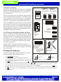
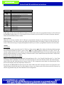
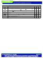
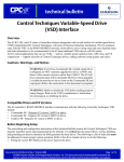
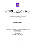
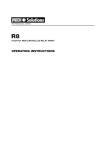
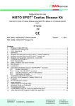
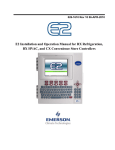
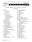
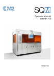
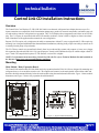
technical bulletin
Control Link CD Installation Instructions
Overview
The Control Link Case Display (CL-CD) (P/N 818-2060) is an electronic refrigerated case display that uses up to five
inputs to monitor case temperature, defrost termination temperature, product or return air temperature, and other sensor values and switches related to refrigerated case operation. The CL-CD displays these temperatures and values on an LED display. The CL-CD may be networked with an E2 RX controller (software version 2.60F01 or higher) to share sensor data
with a Standard Circuit application that controls the case refrigeration.
Because CL-CDs require only a single network cable to communicate with an E2, cases equipped with CL-CDs require significantly less wiring and installation labor than traditional installations (which typically require one cable per sensor run to
a centrally located group of input boards).
The CL-CD may control two external loads directly from its two onboard dry-contact relay outputs, or it may use a pluggable expansion output board (P/N 618-1120 “general purpose” board) with 5 additional relays for satellite output control of
up to 7 loads. The output board requires CL-CD firmware version 2.06 or higher.
NOTE: For information about networking Control Link CD with E2, refer to Technical Bulletin 026-4602 available on
the Internet at http://www.emersonretailsolutions.com/library.
Mounting
Main Module / Relay Expansion Board
The Control Link main module (P/N 818-2060) and relay expansion boards (P/N 618-1120) are designed for mounting on a
refrigerated case or in an enclosure near the case. The output board connects to the main module with a ribbon cable and
therefore should be mounted directly below the main module using the attached stand-off bracket. Figure 1 shows module
dimensions, and Figure 2 shows relay expansion board dimensions.
Figure 1 - Control Link Module Mounting
Figure 2 - Expansion Board Mounting
Document Part # 026-4601 Rev 4 04-AUG-2009
Page 1 of 10
©2009 Emerson Climate Technologies Retail Solutions, Inc. This document may be photocopied for personal use.
Visit our website at http://www.emersonretailsolutions.com/ for the latest technical documentation and updates.
technical bulletin
Control Link CD Installation Instructions
Main Module, Expansion Board, and Remote Display Environment Specifications
Operating Temperature: -20 °C — 60°C (-4°F—140°F)
Operating Humidity: 90% RH non-condensing
Storage Temp: -30—65°C (-22—149°F)
Max Power Consumption: 15W (Control Link w/expansion board)
Remote Display Mounting
The remote display is designed to be mounted on an accessible
part of a refrigerated case or enclosure, no more than 25 feet
from the main module. Do not mount the remote display in an
area where water may be splashed or sprayed on the enclosure.
If flush mounting on a flat surface such as the front of a case or
enclosure, punch a 5/8” square hole in the surface to allow the
protruding RJ45 jack to recess, and then drill 5/32” holes for the
mounting screws using the remote display itself as a template.
Figure 3 shows the dimensions.
Figure 3 - Remote Display Mounting
Power down the main module before connecting the remote
display. Use CAT5 wiring with RJ45 connectors to connect the
Main Module with the Remote Display. Do not exceed a maximum length of 25 feet.
If mounting the unit inside the refrigerated area of the case, insulate the remote display’s RJ45 connector with a dielectric
grease to insulate the connector from moisture contamination.
Wiring
Power (Control Link Module without output board)
When the Control Link module is used without an output board, connect 120240 VAC 50-60 Hz line voltage to the spade lug connectors on the lower right
side of the Control Link module (Figure 4).
Power (Control Link Module with 618-1120 output board)
When the 618-1120 output board is used with a Control Link module, connect
the L and N spade lug terminals on the module to the L and N spade lug terminals on the output board (Figure 4). Connect 120-240 VAC 50-60 Hz line voltage to the screw terminals labeled L and N on the output board. Do not connect
any wire to the middle terminal.
Control Link Module
(front view, bottom right corner)
Power
120
240
L
L1
N
L2
Control Link Module
(front view, bottom right corner)
120V 240V
L
L1
N
L2
Power
120
240
L
L1
N
L2
L
N
Output Bd 618-1120
(front view, right side)
NOTE: The L and N on the screw
terminals are in reverse order
of the L and N spade lug terminals
on the module and on the output board.
120V 240V
N L2
L L1
NO C NC NO C NC
RELAY 6 RELAY 7
Figure 4 - Control Link Power
NOTE: The L and N on the screw terminals are in reverse order of the L and N spade lug terminals on the module and
on the output board.
Sensors
Case temperature and product temperature or return air sensors must be wired to the top three-terminal connector on the left
side of the Control Link module. The defrost termination and coil outlet temperature sensors (if present) must be wired to
the middle three-terminal connector. Use only CPC NTC 10k thermistors. The defrost termination sensor can be either a
10k thermistor or a temperature switch. Wire as shown in Figure 5.
Document Part # 026-4601 Rev 4 04-AUG-2009
Page 2 of 10
©2009 Emerson Climate Technologies Retail Solutions, Inc. This document may be photocopied for personal use.
Visit our website at http://www.emersonretailsolutions.com/ for the latest technical documentation and updates.
technical bulletin
Control Link CD Installation Instructions
Mount the case temp sensor in the discharge air stream for the case. Mount the defrost termination sensor near the evaporator coil. If monitoring case superheat, the defrost termination sensor should be tie-wrapped to the evaporator coil near the
inlet. Case Superheat is calculated by subtracting the defrost termination temperature from the coil outlet temperature and
applying the SH Smoothing parameter. Mount the product temperature sensor anywhere in the refrigerated space. If using
a return air sensor, mount the sensor in the return air stream. The coil outlet sensor must be tie-wrapped to the evaporator
coil at the outlet.
The bottom three-terminal connector may be used for one generic digital sensor. This sensor’s ON/OFF state is sent back to
the E2 as a generic input value, and may be programmed in a Standard Circuit application as a clean switch, door switch, or
any other type of digital input.
NOTE: This input does not support push buttons and momentary switches and may only be used for edge-triggered or
level-triggered switches.
Figure 5 - Sensor Wiring
CL-CD Outputs
On-Board Relay Outputs
Relay 1
RELAY #1
The CL-CD has two on-board relays that may be used as satellite outputs by other E2
applications. Wire the outputs to the two-wire terminals on the right side of the control unit,
as shown in Figure 6. Each of these output points are rated to a maximum of 3A @ 250V.
Relay 2
RELAY #2
For loads greater than 3A, use the outputs to energize external relays.
Figure 6 - CL-CD Outputs
Expansion Board Relay Outputs
Use the Form C contactors on the output board points labeled RELAY
3 through RELAY 7 to connect the satellite outputs you will be using.
Refer to Figure 7, and refer to Table 1 for relay ratings and fail-safe
positions.
ON=OPEN
OFF=CLOSED
ON=CLOSED
OFF=OPEN
FAIL=CLOSED
FAIL=OPEN
Figure 7 - Expansion Board (618-1120) Output Wiring
Document Part # 026-4601 Rev 4 04-AUG-2009
Page 3 of 10
©2009 Emerson Climate Technologies Retail Solutions, Inc. This document may be photocopied for personal use.
Visit our website at http://www.emersonretailsolutions.com/ for the latest technical documentation and updates.
technical bulletin
Control Link CD Installation Instructions
Expansion Board Relay Ratings
#
RELAY 3
RELAY 4
RELAY 5
RELAY 6
RELAY7
Relay Ratings
10A-N.C. or 12A N.O. @ 120-240 VAC
120VAC: 1/2 hp N.O. or N.C., FLA=9.8A, LRA=40A
240VAC: 1 hp N.O. or N.C., FLA=8.0A, LRA=30A
Pilot Duty: 50VA, 24-240VAC
Table 1 - Relay Ratings (Output Board 618-1120)
Networking
CL-CDs communicate with a parent E2 controller using a MODBUS network. Each CL-CD must be equipped with a network card (P/N 618-2080), which plugs into the Control Link main module in the “Network Comm. Bus” socket. The network card has a three-terminal connector for wiring the MODBUS network cable, and a DIP switch bank with eight
switches for assigning the CL-CD a unique network address.
The instructions in this section show how to configure and connect a network, terminate the network, and set addresses and
baud rates. It is strongly recommended you obtain a copy of Technical Bulletin P/N 026-4602, ECT Modbus Networking
to E2s, for complete instructions on configuring a MODBUS network, including grounding and noise minimization techniques, E2 COM port connection details, and E2 software setup.
Daisy-Chaining and Network Connection to Control Link
CL-CDs must be networked together in a daisy-chain configuration (all CDs networked in series from the E2, and terminated at the two end devices). No splits or “star configurations” are allowed. The network cable must be Belden #8761 or
equivalent. Observe network polarity, wiring RS485+ to RS485+, 0V to 0V, and RS485- to RS485- (see Figure 8).
Document Part # 026-4601 Rev 4 04-AUG-2009
Page 4 of 10
©2009 Emerson Climate Technologies Retail Solutions, Inc. This document may be photocopied for personal use.
Visit our website at http://www.emersonretailsolutions.com/ for the latest technical documentation and updates.
technical bulletin
Control Link CD Installation Instructions
Termination and Biasing
TERMINATED,
BIASED
(ALL 3 JUMPERS
IN UP POSITION)
The devices at both ends of the daisy chain must be terminated
using the network termination jumpers. However, unlike the E2
I/O Network, an ECT MODBUS network must be biased on
only one end (the E2).
On the CL-CD network card, the termination and bias jumpers
are located below the network connector. To terminate a device,
set the center jumper to the LEFT position (i.e., toward the rear
of the module). Leave the two outside jumpers in the RIGHT
position (i.e., toward the front of the module). Refer to Figure 8.
Each CL-CD must have a unique network address. The network
address is set by switches 1-6 of the DIP switch bank on the network card. Switches 1-6 correspond to binary digits of the network address (1, 2, 4, 8, 16, and 32 respectively). Each switch in
the UP (ON) position adds the corresponding value to the network address. CL-CDs should be numbered in order starting
with unit #1 (see Figure 8).
Switches 7 and 8 set baud rate and parity. Set switch 7 to
DOWN (OFF) to set the baud rate at 19.2k or UP (ON) for 9600.
Set switch 8 DOWN (OFF) to specify no parity, or UP (ON) to
specify even parity.
E2 Setup of CL-CD Devices
4.
5.
6.
CL-CD
#3
#1
SWITCH #
ADDRESS #
EXAMPLES:
ADDRESS#: 1
SWITCHES 1-6
NETWORK
ADDRESSING
1
ADDRESS#: 2
SWITCH IN "ON" POSITION
ADDS ADDRESS # TO
NETWORK ID
CONTROL
LINK
MODULE
(LEFT SIDE
VIEW)
2
ADDRESS#: 11
1+2 +8
BAUD RATE & PARITY
NETWORK WIRING
(BELDEN #8761 OR
EQUIVALENT)
RS4850V
RS485+
SET SWITCH 7 IN THE
"DOWN" (OFF) POSITION
TO SET BAUD RATE
TO 19200 BAUD, OR
UP (ON) for 9600.
SET SWITCH 8 IN THE
"DOWN" (OFF) POSITION
TO SELECT NO PARITY,
OR UP (ON) TO SPECIFY
EVEN PARITY.
To enable communications between E2 and the CL-CD units,
the devices must be added and addressed in E2.
1.
2.
3.
CL-CD
NETWORK ADDRESSING
NETWORK CARD
If the ECT MODBUS network includes devices other than Control Link, and if one of these devices is the endpoint of the daisy
chain, it may be necessary to use a MODBUS termination block
if the end device has no means of on-board termination. Refer to
Technical Bulletin 026-4602 for more information about ECT
MODBUS networking and termination.
CL-CD Network Addressing, Baud Rate, and Parity
CL-CD
E2
TERMINATED,
UNBIASED
(CENTER JUMPER
IN LEFT POSITION)
Log in to the E2 with Level 4 access.
Press I
- “Connected I/O Boards and Controllers.”
In the Connected I/O screen, in a box labeled “ECT Devices,” there will
be a parameter called CtrlLink CD. In this field, enter the number of CLCDs on the network.
Press J to return to the Network Setup menu, then select - “Controller Setup.”
85RS4 D
TO
L
SHIE
TO
R
5+
48
RS
TO
TO
SH RS
IE 48
LD 5
-
S48
5+
WIRE RS485+ to RS485+
WIRE RS485- to RS485CONNECT SHIELDS TO 0V
(MIDDLE TERMINAL)
TERMINATION JUMPER SETTINGS
UNTERMINATED
TERMINATED,
UNBIASED
Figure 8 - CL-CD Networking
Locate the CtrlLink CaseDisp units you added to the network list (press 8 and 7 to scroll through the list). The default name for a CL-CD is a
code string beginning with “.CD”. If desired, enter a new name for each device in the Name field.
By default, each CtrlLink CaseDisp in the network list has a board number of 0. To set the address and begin communication, press D and
select - “Select Address.” In the list of MODBUS devices, choose the address number corresponding to the CL-CD’s dip switch setting, and
press > to select it.
Document Part # 026-4601 Rev 4 04-AUG-2009
Page 5 of 10
©2009 Emerson Climate Technologies Retail Solutions, Inc. This document may be photocopied for personal use.
Visit our website at http://www.emersonretailsolutions.com/ for the latest technical documentation and updates.
technical bulletin
Control Link CD Installation Instructions
Repeat steps 5 and 6 until each CL-CD device has a name and address. When finished, press J to return to the Network
Setup menu, then press - “Controller Status.” Locate the CL-CDs you set up, and verify their status reads “Online.” If
not, verify the CL-CD is powered up, wired correctly, and has the proper network address, baud rate, and parity.
CL-CD Software Setup
Once a CL-CD unit has been added and is online on the E2 MODBUS network, the CL-CD itself must be programmed.
This is typically done from the E2 front panel, since the CL-CD is designed to interface with the E2 and many CL-CD features (such as satellite output configuration) may only be programmed from the E2 front panel.
If a CL-CD must be installed with no available access to E2 (either because it is stand-alone or because E2s have not been
installed yet), you may wish to configure the CL-CD from the Control Link main module or remote display interface. Refer
to “Configuring CL-CD From The Control Link Interface,” page 8.
Configuring CL-CD Through E2
1.
2.
3.
4.
5.
6.
7.
While logged in to the E2 with Level 4 access, press I - CONFIGURED APPLICATIONS.
Select “100. Control Link CD”
If there are multiple CL-CDs, highlight the application name whose number corresponds to the network address of the CL-CD you wish to set up
(i.e., “CL CD001” for CL-CD #1).
From the CL-CD’s status screen, press E - SETUP.
The parameters in these setup screens can be used to specify which inputs are present, the case name or defrost override message, sensor offsets,
and other important functions. The E2 Online Help will explain the function of each parameter - to access Online Help, highlight the parameter
you need assistance with, and press F.
When all parameters are set properly, press J to return to the CL-CD’s status screen.
From the status screen, press > and select 9. Application Commands. Application commands allow you to clear alarms in the CL-CD, send
configuration from E2 down to the CL-CD, or receive configuration from the CL-CD. Select 3. Snd E2 Cnfg to Device.
Repeat steps 1-7 until all CL-CDs are set up.
E2 Circuit Association
The final step in setting up an E2 MODBUS network with Control Link CDs is associating the Standard Circuit applications in the E2 with the CL-CDs they are attached to. Refer to the E2 user manual for information on how to add and configure standard circuits.
1.
2.
Log in to the E2 with level 4 access.
Press C - CIRCUITS to view the circuit summary screen.
3.
4.
•
Highlight the circuit you wish to configure, then press E - SETUP.
In Setup screen C1: General, set the following two parameters:
Num Case Sensrs: Enter the number of CL-CDs on this circuit.
•
Num Prod Sensrs: If the CL-CDs on this circuit have sensors on input #2, enter the number of these sensors.
•
Using Case Disp: Set to Yes, indicating the case temperature and other temps related to this circuit are being supplied by CL-CDs.
5.
Press B to move to Setup screen C2: Case Disp. This screen will show a number of Case Display fields equal to the number entered in Num
Case Sensrs (step 4). For each field, press D - LOOK UP and select the application name whose number corresponds to the network address
number of the CL-CD you want to associate. For example, if you want to associate CL-CD #7 with this circuit, select CL CD007 from the LookUp Table.
Once associated, the Standard Circuit will automatically receive discharge air, termination temperature, and product temperature (either by sensor or calculation) from the CL-CDs.
Document Part # 026-4601 Rev 4 04-AUG-2009
Page 6 of 10
©2009 Emerson Climate Technologies Retail Solutions, Inc. This document may be photocopied for personal use.
Visit our website at http://www.emersonretailsolutions.com/ for the latest technical documentation and updates.
technical bulletin
Control Link CD Installation Instructions
Operation
ALARM LED
SET
BUTTON
UP ARROW
BUTTON
The Control Link module display is primarily used to view temperatures and other
information about the case circuit, and secondarily to program the CL-CD or clear
alarms. The display on the front of the Control Link module and the remote display unit commonly used with CL-CD are identical and are used the same way.
Seven-Segment Display
7-SEGMENT LED DISPLAY
The four-digit seven-segment display is the primary means a technician or operator will use for viewing temperatures and alarm codes, and programming setpoints.
ALARM SILENCE
BUTTON
DOWN ARROW
BUTTON
Figure 9 - CL-CD Display
Alarm LEDs
The ALARM LED is located on the left side of the display directly above the seven-segment LEDs. This LED is ON to
indicate one or more of the following alarm conditions are active for that case:
•
A temperature sensor open or short on the CL-CD itself (see “Alarms” on page 8),
•
A “Case Temp Hi Limit Exceeded” alarm from the E2, indicating the CL-CD’s case temperature sensor has exceeded the Case Temp Hi setpoint
in the Standard Circuit to which the CL-CD is associated, or
•
A “Case Temp Lo Limit Exceeded” alarm from the E2, indicating the CL-CD’s case temperate sensor has fallen below the Case Temp Lo setpoint
in the Standard Circuit to which the CL-CD is associated.
Active Case Temp Hi and Case Temp Lo alarms are the only E2-generated alarms that will cause the CL-CD’s Alarm LED
to be ON. Combined case temp hi/lo alarms, product temperature alarms, etc. will not affect the Alarm LED.
Buttons
The four buttons to the right of the seven-segment display are used to program the CL-CD, select temperatures and alarms
for viewing, and perform other functions such as alarm clearing.
Output Relay Control
The two on-board relays on the CL-CD and the five Relay Expansion Board (618-1120) relays (if present) are controlled by
the associated Control Link CD application in the E2. To control these relays, you must connect the application’s RELAY x
COMMAND input (where x is the relay number) to the output of another application in the E2 (such as a schedule to control lighting). Refer to the E2 Manual, P/N 026-1610, for information on setting up input definitions.
Modes of Operation
Case Temperature Display (Normal Mode)
When the case circuit is not in defrost and no alarms are active, the CL-CD display shows a temperature. The user may
select any of the four temperature inputs on the CL-CD as the default display temperature (by default, the CL-CD shows
the discharge air temperature).
In this mode, you may view the values of all the other inputs and outputs by pressing the DOWN arrow button. Each time
the DOWN arrow button is pressed, a message will be displayed for one second to indicate what input or output value will
be shown, followed by the current value
Document Part # 026-4601 Rev 4 04-AUG-2009
Page 7 of 10
©2009 Emerson Climate Technologies Retail Solutions, Inc. This document may be photocopied for personal use.
Visit our website at http://www.emersonretailsolutions.com/ for the latest technical documentation and updates.
technical bulletin
Control Link CD Installation Instructions
Msg Displayed
Sensor Value Displayed
dA
Discharge air sensor value (Input #1)
Pr
Product temperature (Input #2)
DF
Defrost termination temperature or switch state (Input #3)
CO
Coil outlet temperature (Input #4)
DI
Generic digital input (Input #5)
SH
The calculated coil superheat, if #3 and #4 have thermistors.
rly1
State of generic relay #1
rly2
State of generic relay #2
rly3
State of generic relay #3
rly4
State of generic relay #4
rly5
State of generic relay #5
rly6
State of generic relay #6
rly7
State of generic relay #7
In this mode, you may also use the UP arrow button to view the name of the case (programmed for the CL-CD via E2) and
the MODBUS address of the CL-CD. Pressing the UP arrow button cycles between the case name (if defined; otherwise,
blank) and the MODBUS address number.
Defrost Mode
When the case circuit is in defrost, the CL-CD may be programmed to display any four-character message instead of the
default temperature. This feature ensures the higher case temperatures that occur during a defrost cycle do not alarm customers. The defrost message is displayed throughout the defrost cycle and for a programmed amount of time afterwards.
Alarms
CL-CD Alarms
If a temperature sensor connected to the CL-CD fails, an alarm message “tS” will be displayed indicating which input number has failed and whether the sensor is open or short. “tS1O”, for example, indicates temp sensor #1 is open. The CL-CD
will also send this alarm to the E2’s Advisory Log. Press the ALARM SILENCE button to clear the alarm message and display the default temperature (or defrost message, if in defrost mode). If the condition that caused the alarm is still present,
the alarm will re-occur after one minute.
E2 Alarms (Case Temp Hi and Case Temp Lo)
When a CL-CD is associated with a Standard Circuit application in E2, a “Case Temp Hi Limit Exceeded” or “Case Temp
Lo Limit Exceeded” alarm that occurs for the CL-CD’s associated case will cause the main module and remote display’s
Alarm LED to turn ON, indicating an active alarm. Unlike CL-CD’s temperature sensor alarms, no alarm message will be
shown on the display when case temperature alarms occur.
Pressing the ALARM SILENCE button will cause the Alarm LED to turn OFF. It will also reset the Case Temp Hi or Case
Temp Lo alarms in the E2 Advisory Log. If the alarm re-occurs, a new alarm record will be written to the E2 Advisory Log
after the programmed delay time in the Standard Circuit configuration.
Document Part # 026-4601 Rev 4 04-AUG-2009
Page 8 of 10
©2009 Emerson Climate Technologies Retail Solutions, Inc. This document may be photocopied for personal use.
Visit our website at http://www.emersonretailsolutions.com/ for the latest technical documentation and updates.
technical bulletin
Control Link CD Installation Instructions
Multiple Alarms
If more than one CL-CD related alarm is active, the CL-CD display will only display the first alarm that occurred. All other
alarms will only be visible from the E2 Advisory Log. Pressing the ALARM SILENCE button returns all alarms to normal
both on the CL-CD display and the E2 Advisory Log.
NOTE: It is recommended you manage alarms through the E2 Advisory Log instead of the CL-CD interface. Viewing
and resetting the alarms through E2 will ensure you are aware of all alarms affecting the case, and you can reset or
clear individual alarms when necessary.
Configuring CL-CD From The Control Link Interface
SET
BUTTON
ALARM LED
1.
2.
3.
UP ARROW
BUTTON
Clear any active alarms by pressing the ALARM SILENCE button.
Press and hold the UP and DOWN arrow buttons simultaneously for five seconds.
When the display shows APAS, press the SET button and use the arrow buttons to select the correct password (default is 0000). Press the SET button to enter the password.
The display will show the first programmable parameter: LF (line frequency). The arrow buttons
may be used to scroll through the list of general parameters. To change the value of any parameter:
1.
2.
3.
4.
5.
6.
7.
ALARM SILENCE
DOWN ARROW
Select the parameter using the arrow buttons (until the code is shown) and press the SET but7-SEGMENT LED DISPLAY
BUTTON
BUTTON
Figure 10 - CL-CD Display
ton.
The current value of this parameter will be displayed. Use the arrow buttons to change the
value.
Press the SET button to accept value.
Repeat steps 1 - 4 until all setpoints have been properly configured.
When finished, press and hold the SET button to save changes and exit. After approximately 5 seconds, the display will go blank and then revert
to normal display to indicate setpoints have been saved.
To cancel all changes, press and hold the SILENCE button for five seconds, or leave the controller idle for 60 seconds. You will lose all setpoint
changes made since you entered general programming mode.
CAUTION!
To make changes permanent, you MUST press and hold the SET button
for five seconds. Leaving the controller idle for 60 seconds will log you
out and cancel all of your setpoint changes.
If this CL-CD is connected to an E2, you must save the CL-CD’s settings in the E2. Press I and select 100. Control Link CD. Highlight
the application whose number corresponds to the network address number of the CL-CD you programmed in Steps 1 - 5 above. From the Status
Screen that appears, press > and select 9. Application Commands. Select 2. Send Device Cfg to E2.
Advanced Parameters
Code
Description
Min
Max
Default
LF
Input power line frequency (Hz)
50
F C
Temperature units (this affects units for both display and setpoints)
F
C
F
S1Pr
If the discharge air sensor is connected to input #1, set this parameter to yES.
no
yES
yES
S2Pr
If a product temp or return air temperature sensor is connected to input #2, set this parameter to yES.
no
yES
no
S3Pr
If the defrost termination sensor is connected to input #3, set this parameter to yES.
no
yES
no
S4Pr
If the coil outlet temperature sensor is connected to input #4, set this parameter to yES.
no
yES
no
S5Pr
If the generic digital input (#5) is being used and has a switch or digital sensor connected, set this parameter to yES.
no
yES
no
Smoothing factor for Superheat calculation (higher values cause the calculated Superheat to respond slower to changes in Superheat)
1
10
5
Default sensor value to display during normal operation (select input #; default is discharge air (#1)).
1
4
1
For the generic digital input, defines whether the input is edge-triggered or level-triggered.
EdgE
LvL
EdgE
SHA
dSdP
CLt
Ornt
Ordt
Text to display during defrost. This may not be set through the CL-CD keypad input, but you may view its value by pressing SET. This
must be programmed through E2.
Time after defrost ends that the defrost message (Ornt) will continue to be displayed (minutes).
60
60
def
0
60
1
Document Part # 026-4601 Rev 4 04-AUG-2009
Page 9 of 10
©2009 Emerson Climate Technologies Retail Solutions, Inc. This document may be photocopied for personal use.
Visit our website at http://www.emersonretailsolutions.com/ for the latest technical documentation and updates.
technical bulletin
Control Link CD Installation Instructions
Advanced Parameters
Code
Description
CASn
dFtt
Case name displayed when the UP arrow button is pressed. This may not be set through the CL-CD keypad input, but you may view
its value by pressing SET. This must be programmed through E2.
If a sensor is connected to input #2, this determines how product temperature is calculated. If #2 is a product temp sensor (SNSR), the
raw value of the sensor will be used as the product temp. If #2 is a return air temp sensor (CAL), product temp will be calculated by
weighted average of the discharge and return air temperatures (PrCt).
Weight (in percentage) of the discharge air sensor value (#1) in calculating the product temperature, if CAL is used as the product temp
method. For example, if PrCt is 60, 60% of input #1 will be added to 40% of input #2 to yield the product temperature.
Fail-safe state of relays if communication is lost with the E2. Relay #1 and #2 refer to the on-board relays on the CL-CD main module;
relays #3 through #7 refer to the relays on the Expansion Relay Board (if one is being used). Refer to Figure 7 for a diagram showing
the relay numbers.
Input type of defrost termination sensor (#3). Choose NTC if a temp sensor, or DIG if a temperature switch.
CAL1 - CAL4
Calibration offsets of the temperature inputs #1, #2, #3, and #4. If a sensor is giving a high or low reading, enter an offset to correct it.
-10
10
0
The password required to edit settings from the CL-CD keypad.
0000
9999
0000
PRMD
PrCt
rly1 - rly7
APAS
SFt
Min
Max
Default
blank
SNSR
CAL
SNSR
0
100
50
OFF
ON
OFF
NTC
DIG
NTC
Software revision number. This field is read-only.
Document Part # 026-4601 Rev 4 04-AUG-2009
Page 10 of 10
©2009 Emerson Climate Technologies Retail Solutions, Inc. This document may be photocopied for personal use.
Visit our website at http://www.emersonretailsolutions.com/ for the latest technical documentation and updates.