1
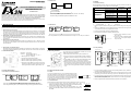
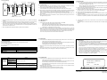
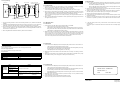
2.3 Wiring
2.3.1 Selection of Wiring
Wiring of RS485 is one-pair wiring or two-pair wiring. The wiring method is decided according to the
usage. Please select the wiring method from the table below.
FX2N-485-BD COMMUNICATION BOARD
HARDWARE MANUAL
JY992D73401A
This manual contains text, diagrams and explanations which will guide the reader in the correct installation
and operation of the FX2N-485-BD COMMUNICATION BOARD. It should be read and understood before
attempting to install or use the unit. Further information can be found in the FX PROGRAMMING MANUAL, FX2N series hardware manuals and manual of FX COMMUNICATION USER’S MANUAL.
➀ FX2N+485BD
➁ FX2N+FX2N-CNV-BD
+FX0N-485ADP
➂ FX(2C)+FX2-40AW
When using 485BD in system, this distance is 50m. (No use : max. 500m)
But, when using FX2-40AW in system, this distance is 10m.
Dedicated protocol
(Use computer link) *1
The communication board FX2N-485-BD for RS485 (hereinafter referred to as “485BD”) can be connected
to the base unit of the FX2N Series programmable controller to be used for the following applications.
1) Data transfer using no protocol
Data communication with diversified RS232C units including personal computers, bar code readers
and printers can be performed via the RS485 (422) converter using the no protocol. In this application, data is sent or received using the data registers specified by the RS instruction. For the setting
and program examples, refer to the FX Programming Manual and FX Communication User’s Manual.
2) Data transfer using the dedicated protocol
Data transfer with RS485 (422) units can be performed on the 1:N basis using the dedicated protocol.
For the contents of the dedicated protocol used in this application, refer to the FX Communication
User’s Manual.
¤*2
¡
×
¡
If is necessary to set the message wait to 70ms or less
×
¡
If is not necessary to set the
message wait to 70ms or less
¤*2
¡
×
¡
Parallel link (Refer to section 2.3.4) *4
¤
¡
N:N network
¡
×
Use on-demand function
¤ . . . . Recommendation, ¡ . . . . .OK,
1.2.3 N:N Network
Master
FX2N
485BD
Slave
Slave
FX2N+FX2NCNV-BD/
FX0N
FX2N
485BD
FX0N-485ADP
Slave
FX2N
*2 When using 485BD with, this wiring method remember to take account of/or ignore the “echo” of the
commands sent from the FX2N programmable controller.
*3 Use FX2N programmable controller and 485BD together.
485BD
*4 For excluding the combination of 485BD, please see below.
When using 485BD in the system, total extension distance is 50m (No use : max. 500m), max.8 stations.
FX 2 -40AW
485BD
SA
SD A
SB
SD B
SG **1
RDA
**1 Connect the SG terminal to SG terminal of FX or
FX2C main unit.
Term inating resistance
110Ω
RDB
SG
G rounding of resistance 100Ω or less
R S 48 5/42 2 u nit
F X (O N ) -4 85 A D P
SDA
SDA
SDA
SDA
SDB
SDB
SDB
SDB
RDA
RDA
RDA
RDA
ƒ Fix the 485BD to the base unit using the M3 self-tapping screws
supplied. Tightening torque: 0.3 to 0.6 N•m (3 to 6 kgf•cm)
RDB
RDB
RDB
RDB
„ Remove the cut out on the left of the panel cover using a tool
such as nippers or cutters so that the terminal block is accessible.
The top face of this terminal block is higher than the top face of
the panel cover of the programmable controller by approximately
7 mm.
SG
SG
L IN K
SG
*3
FG
SG
*3
FG
Accessory
• Remove the panel cover from the top face of the base unit.
: M3 self-tapping screw×2,
Terminal resistor 330Ω×2, 110Ω×1
‚ Connect the connector for programmable controller provided on
the 485BD to the board mounting connector provided on the base
unit.
‚ Connector for programmable controller
ƒ SD LED: Flashes at high speed during sending.
„ RD LED: Flashes at high speed during receiving.
… Terminals to connect RS485 unit The top face of this terminal block is higher than the top face of the panel cover
of the programmable controller by approximately 7mm.
1.2 System Configuration
2.2 Cable and Terminal Resistor
1.2.1 No Protocol or Dedicated Protocol
2.2.1 Cable
485BD
FX(0N)-485ADP
A series
A series
Porgrammable controller's
computer link unit
When using 485BD in the system, total extension distance is 50m. (No use : max. 500m)
When using dedicated protocol, max.16 stations including A series programmable controller.
A se ries p rog ra m m a ble
controlle r 's com pu ter lin k u nit
48 5B D
Turn off the power of the programmable controller, and mount the
485BD using the following procedure.
• Mounting holes (2∅- 4.0(0.16"))
FX2N
2.3.2 Two-pair Wiring
2. MUNTING AND WIRING
Dimensions : mm(inches)
FX/FX2C/
FX0N
**2 Connect the shield of shielded twisted pair cable to
ground (100Ω or less).please adjust the grounding
only to one side.
**2
2.1 Mounting Procedure
1.1 External Dimensions
× . . . . . Can not use
*1 When this product is added to the system, please match the wiring to the wiring method of the system.
3) Data transfer using the parallel link
Data transfer with an FX2N programmable controller can be performed on the 1:1 basis for 100 auxiliary relays and 10 data registers. For the setting and program examples, refer to the FX Communication User’s Manual.
4) Data transfer using the N:N network
Data transfer with FX2N programmable controllers can be performed on the N:N basis. For the setting,
the number of transferred data and program examples, refer to the FX Communication User’s Manual.
Two-pair wiring
(Refer to section2.3.2)
Full-duplex communication *3
Half-duplex communication
No protocol
(Use RS instruction) *1
If in doubt at any stage during the installation of the FX2N-485-BD COMMUNICATION BOARD always consult a professional electrical engineer who is qualified and trained to the local and national standards.
1. INTRODUCTION
One-pair wiring
(Refer to section2.3.3)
Usage
485BD FX2N
To connect the RS485 (422) unit, use a shielded twisted-pair cable.
The cable specification must be AWG 26 to 16, and the maximum tightening torque must be 0.6 N•m (6 kgf•cm). If a cable other than the AWG
26 to 16 is used, normal communication cannot be assured because
the terminal may be imperfectly contacted. It is recommended to insert
a cable integrated by the crimping tool into the terminal.
R *1
R *1
*2
R *1
R *1
G ro und ing of re sista nce 1 00 o r le ss
*1 R is the terminating resistance. Connect the terminating resistance (330Ω) between terminals SDA
and SDB, and terminals RDA and RDB.
*2 The shield of the shielded twisted-pair cable must be connected to ground (100Ω or less). When using
parallel link, ground both side. When using no protocol or dedicated protocol, ground one side.
*3 Connect terminal FG to each terminal of the programmable controller main body grounded with resistance of 100 or less. However, for the computer link unit of the A series programmable controller, see
the manual of the computer link unit.
6m m
*4 When using RS232/485 or RS232/422 interface, please the use FX-485PC-IF.
2.2.2 Terminal Resistor
Provide the terminal resistor at both ends of the line as described in section 2.3.2 and 2.3.3.
1) In the case of two-pair wiring, connect the terminal resistor (330Ω, 1/4W)
between terminals SDA and SDB as well as between terminals RDA and RDB.
Use the resistors offered as accessories of the 485BD.
Orange Orange
Brown
2) In the case of one-pair wiring, connect the terminal resistor (110Ω, 1/2W)
between terminals RDA and RDB. Use the resistors offered as accessories of
the 485BD.
Brown
Brown
Brown
2.3 Wiring
1.2.2 Parallel Link
2.3.1 Selection of Wiring
Wiring of RS485 is one-pair wiring or two-pair wiring. The wiring method is decided according to the
usage. Please select the wiring method from the table below.
FX2N-485-BD COMMUNICATION BOARD
HARDWARE MANUAL
JY992D73401A
This manual contains text, diagrams and explanations which will guide the reader in the correct installation
and operation of the FX2N-485-BD COMMUNICATION BOARD. It should be read and understood before
attempting to install or use the unit. Further information can be found in the FX PROGRAMMING MANUAL, FX2N series hardware manuals and manual of FX COMMUNICATION USER’S MANUAL.
➀ FX2N+485BD
➁ FX2N+FX2N-CNV-BD
+FX0N-485ADP
➂ FX(2C)+FX2-40AW
Usage
485BD FX2N
Dedicated protocol
(Use computer link) *1
1) Data transfer using no protocol
Data communication with diversified RS232C units including personal computers, bar code readers
and printers can be performed via the RS485 (422) converter using the no protocol. In this application, data is sent or received using the data registers specified by the RS instruction. For the setting
and program examples, refer to the FX Programming Manual and FX Communication User’s Manual.
2) Data transfer using the dedicated protocol
Data transfer with RS485 (422) units can be performed on the 1:N basis using the dedicated protocol.
For the contents of the dedicated protocol used in this application, refer to the FX Communication
User’s Manual.
¡
×
¡
If is necessary to set the message wait to 70ms or less
×
¡
If is not necessary to set the
message wait to 70ms or less
¤*2
¡
×
¡
Parallel link (Refer to section 2.3.4) *4
¤
¡
N:N network
¡
×
¤ . . . . Recommendation, ¡ . . . . .OK,
1.2.3 N:N Network
The communication board FX2N-485-BD for RS485 (hereinafter referred to as “485BD”) can be connected
to the base unit of the FX2N Series programmable controller to be used for the following applications.
¤*2
Full-duplex communication *3
Use on-demand function
If in doubt at any stage during the installation of the FX2N-485-BD COMMUNICATION BOARD always consult a professional electrical engineer who is qualified and trained to the local and national standards.
1. INTRODUCTION
Master
FX2N
485BD
Slave
Slave
FX2N+FX2NCNV-BD/
FX0N
FX2N
485BD
FX0N-485ADP
Slave
FX2N
*2 When using 485BD with, this wiring method remember to take account of/or ignore the “echo” of the
commands sent from the FX2N programmable controller.
*3 Use FX2N programmable controller and 485BD together.
485BD
*4 For excluding the combination of 485BD, please see below.
When using 485BD in the system, total extension distance is 50m (No use : max. 500m), max.8 stations.
FX 2 -40AW
485BD
SA
SD A
SB
SD B
SG **1
RDA
**1 Connect the SG terminal to SG terminal of FX or
FX2C main unit.
Term inating resistance
110Ω
RDB
SG
G rounding of resistance 100Ω or less
R S 48 5/42 2 u nit
F X (O N ) -4 85 A D P
SDA
SDA
SDA
SDA
SDB
SDB
SDB
SDB
RDA
RDA
RDA
RDA
ƒ Fix the 485BD to the base unit using the M3 self-tapping screws
supplied. Tightening torque: 0.3 to 0.6 N•m (3 to 6 kgf•cm)
RDB
RDB
RDB
RDB
„ Remove the cut out on the left of the panel cover using a tool
such as nippers or cutters so that the terminal block is accessible.
The top face of this terminal block is higher than the top face of
the panel cover of the programmable controller by approximately
7 mm.
SG
SG
L IN K
SG
*3
FG
SG
*3
FG
Accessory
• Remove the panel cover from the top face of the base unit.
: M3 self-tapping screw×2,
Terminal resistor 330Ω×2, 110Ω×1
‚ Connect the connector for programmable controller provided on
the 485BD to the board mounting connector provided on the base
unit.
‚ Connector for programmable controller
ƒ SD LED: Flashes at high speed during sending.
„ RD LED: Flashes at high speed during receiving.
… Terminals to connect RS485 unit The top face of this terminal block is higher than the top face of the panel cover
of the programmable controller by approximately 7mm.
1.2 System Configuration
2.2 Cable and Terminal Resistor
1.2.1 No Protocol or Dedicated Protocol
2.2.1 Cable
485BD
FX/FX2C/
FX0N
FX(0N)-485ADP
A
C A series
P
U
A series
Porgrammable controller's
computer link unit
When using 485BD in the system, total extension distance is 50m. (No use : max. 500m)
When using dedicated protocol, max.16 stations including A series programmable controller.
A se ries p rog ra m m a ble
controlle r 's com pu ter lin k u nit
48 5B D
Turn off the power of the programmable controller, and mount the
485BD using the following procedure.
• Mounting holes (2∅- 4.0(0.16"))
FX2N
2.3.2 Two-pair Wiring
2. MUNTING AND WIRING
Dimensions : mm(inches)
RS422/485 Unit
**2 Connect the shield of shielded twisted pair cable to
ground (100Ω or less).please adjust the grounding
only to one side.
**2
2.1 Mounting Procedure
1.1 External Dimensions
× . . . . . Can not use
*1 When this product is added to the system, please match the wiring to the wiring method of the system.
3) Data transfer using the parallel link
Data transfer with an FX2N programmable controller can be performed on the 1:1 basis for 100 auxiliary relays and 10 data registers. For the setting and program examples, refer to the FX Communication User’s Manual.
4) Data transfer using the N:N network
Data transfer with FX2N programmable controllers can be performed on the N:N basis. For the setting,
the number of transferred data and program examples, refer to the FX Communication User’s Manual.
Two-pair wiring
(Refer to section2.3.2)
Half-duplex communication
No protocol
(Use RS instruction) *1
When using 485BD in system, this distance is 50m. (No use : max. 500m)
But, when using FX2-40AW in system, this distance is 10m.
One-pair wiring
(Refer to section2.3.3)
To connect the RS485 (422) unit, use a shielded twisted-pair cable.
The cable specification must be AWG 26 to 16, and the maximum tightening torque must be 0.6 N•m (6 kgf•cm). If a cable other than the AWG
26 to 16 is used, normal communication cannot be assured because
the terminal may be imperfectly contacted. It is recommended to insert
a cable integrated by the crimping tool into the terminal.
R *1
R *1
*2
R *1
R *1
G ro und ing of re sista nce 1 00 o r le ss
*1 R is the terminating resistance. Connect the terminating resistance (330Ω) between terminals SDA
and SDB, and terminals RDA and RDB.
*2 The shield of the shielded twisted-pair cable must be connected to ground (100Ω or less). When using
parallel link, ground both side. When using no protocol or dedicated protocol, ground one side.
*3 Connect terminal FG to each terminal of the programmable controller main body grounded with resistance of 100 or less. However, for the computer link unit of the A series programmable controller, see
the manual of the computer link unit.
6m m
*4 When using RS232/485 or RS232/422 interface, please the use FX-485PC-IF.
2.2.2 Terminal Resistor
Provide the terminal resistor at both ends of the line as described in section 2.3.2 and 2.3.3.
1) In the case of two-pair wiring, connect the terminal resistor (330Ω, 1/4W)
between terminals SDA and SDB as well as between terminals RDA and RDB.
Use the resistors offered as accessories of the 485BD.
Orange Orange
Brown
2) In the case of one-pair wiring, connect the terminal resistor (110Ω, 1/2W)
between terminals RDA and RDB. Use the resistors offered as accessories of
the 485BD.
Brown
Brown
Brown
2.3.3 One-pair Wiring
R S485 unit
R *1
FX (O N ) -485A DP
485BD
A series program m able
controller ' s com puter link unit
4. DIAGNOSTICS
SDA
SDA
SDA
4.1 Common Items
SDB
SDB
SDB
SDB
1) Check the connection with the communication unit of the programmable controller and the wiring.
When the connection is unstable, the communication can not be corrected.
RDA
RDA
RDA
RDA
RDB
RDB
RDB
RDB
SG
SG
L IN K
SG
*3
FG
SG
*3
FG
*2
*1 R is the terminating resistance. Connect the terminating resistance (110Ω) between terminals RDA
and RDB.
*2 The shield of the shielded twisted-pair cable must be connected to ground (100Ω or less). When using
parallel link, ground both side. When using no protocol or dedicated protocol, ground one side.
*3 Connect terminal FG to each terminal of the programmable controller main body grounded with resistance of 100 or less. However, for the computer link unit of the A series programmable controller, see
the manual of the computer link unit.
*4 When using RS232/485 or RS232/422 interface, please the use FX-485PC-IF.
-
If the RD (RXD) LED is not lit while data is received or the SD (TXD) LED is not lit while data is
sent, check the installation and the wiring.
-
When the RD (RXD) LED is lit while data is received or the SD (TXD) LED is lit while data is
sent, the installation and the wiring are correct.
2) Check whether the VRRD or VRSC instruction is used in used in the program.
If it is used, delete it, turn off the power of the programmable controller, then turn it on again.
2) Make sure the timing of data send/receive. For example, make sure that the counterpart equipment is
ready for receive before starting to send data to it.
3) Each setting of communication format (D8120), parameter of programmable controller by FX-PCS/
WIN-E, N:N network (D8173 to D8180) and parallel link (M8070, M8071) is suitable for the usage or it
checks. The communication is not correctly done if setting is not suitable for the usage.
When each setting is changed, please turn off the power supply of the programmable controller, and
turn it on again.
3) When the terminator is not used, check whether the send data capacity is equivalent to the acceptable data capacity. If the send data capacity may be changed, use the terminator.
4) When you use FX0N-485ADP or FX-485ADP in network, please the power supply for the drive must
be supplied correctly or check.
G rounding of resistance 100 or less
1) Check the status of the RD (RXD) LED and the SD (TXD) LED provided in an optional equipment.
For error code of N:N network and computer link, refer to the FX Communication User’s Manual.
SDA
R *1
4.5 RS Instruction
4.2 LED Check Items
4.2.1 N:N Network
1) Check the status of the RD LED and the SD LED provided on each 485BD.
-
If both of them are lit and extinguished, nothing is wrong.
-
If the RD LED is lit/extinguished but the SD LED is not lit/extinguished (not lit at all), check the
setting of the station No.,the baud rate (transmission rate) and the total number of salve stations.
-
If the RD LED is not lit/extinguished, check the wiring.
4) Make sure that the external equipment is correctly operating.
5) Check whether the type of send data and the type of receive data are equivalent. If they are different,
make them equivalent.
6) When two or more RS instructions are used in the program, make sure that only one RS instruction is
actuated in one operation cycle. Never turn off the RS instruction while data is received or sent.
7) In the FX2N Series (V2.00 or later), an RS instruction is not executed if the counterpart equipment
receives “NAK”.
Arrange the system so that the RS instruction is executed even if the counterpart equipment receives
“NAK”.
2) Make sure that the communication error (FX2N: M8183 to M8190, FX0N: M504 to M511) in each slave
station is not turned on and that the data communication flag (FX 2N: M8191, FX 0N: M503) is not
turned off. When one of the communication error flag is turned on or if the data communication flag is
turned off, check the error code of data registers (FX 2N: D8211 to D8218, FX0N: D211 to D218).
For the error code, please see the FX Communication User’s Manual.
4.3 Parallel Link
3. SPECIFICATIONS
3.1
1) Check the status of the RD(RXD) LED and the SD(TXD) LED provided on each communication unit.
General Specifications
General specifications are the same as those for the FX2N series programmable controller.
3.2
3.3
-
If both of them are lit and extinguished, nothing is wrong.
•
-
If the RD(RXD) LED is lit/extinguished but the SD(TXD) LED is not lit/extinguished (not lit at all),
check the setting of the master station and the slave stations.
This manual has been written to be used by trained and competent personnel. This is defined
by the European directives for machinery, low voltage and EMC.
•
-
If the RD(RXD) LED is not lit/extinguished, check the wiring.
If in doubt at any stage during the installation of the FX2N-485-BD always consult a professional electrical engineer who is qualified and trained to the local and national standards. If in
doubt about the operation or use of the FX2N-485-BD please consult the nearest Mitsubishi
Electric distributor.
•
Under no circumstances will Mitsubishi Electric be liable or responsible for any consequential
damage that may arise as a result of the installation or use of this equipment.
•
All examples and diagrams shown in this manual are intended only as an aid to understanding the text, not to guarantee operation. Mitsubishi Electric will accept no responsibility for
actual use of the product based on these illustrative examples.
•
Owing to the very great variety in possible application of this equipment, you must satisfy
yourself as to its suitability for your specific application.
Power Supply Specification
5V DC, 60 mA is supplied from the programmable controller.
2) Make sure that the master station and the slave stations are set correctly. If the setting is incorrect,
correct it.
Specification
Item
Content
Transmission standard
Conforming to RS485 and RS422
Transmission distance
Max. 50 m
LED indicators
SD, RD
Item
Content
Dedicated protocol
(format 1 or format 4)
3) Make sure that the devices for the master station and the slave stations are handled correctly. If they
are handled incorrectly, correct the program so that they are handled correctly.
4.4 Computer Link
1) Check the status of the RD(RXD) LED and the SD(TXD) LED provided on each communication unit.
N:N network
Communication method
and protocol
Guidelines for the safety of the user and protection of the FX2N-485-BD Communication Board
Half-duplex communication
-
If both of them are lit and extinguished, nothing is wrong.
-
If the RD(RXD) LED is lit/extinguished but the SD(TXD) LED is not lit/extinguished (not lit at all),
check the setting of the station No. and the transmission rate (baud rate).
-
If the RD(RXD) LED is not lit/extinguished, check the wiring and confirm the connection with the
programmable controller.
Parallel link
No protocol
Full-duplex communication
Supported baud rate
Dedicated protocol and no protocol: 300 ~ 19,200 (bps)
Parallel link
: 19,200 (bps)
N:N network
: 38,400 (bps)
2) Make sure that the communication procedure is performed correctly. If it is not performed correctly,
correct the setting in the computer.
Isolation
No isolation
3) Check the NAK error code and programmable controller error code.
For the error code, please see the FX Communication User’s Manual.
Manual number : JY992D73401
Manual revision : A
Date
: MAY 1998
HEAD OFFICE : MITSUBISHI DENKI BLDG MARUNOUTI TOKYO 100 TELEX : J24532 CABLE MELCO TOKYO
HIMEJI WORKS : 840, CHIYODA CHO, HIMEJI, JAPAN
JY992D73401A
Effective MAY 1998
Specifications are subject to
change without notice
2.3.3 One-pair Wiring
R S485 unit
R *1
FX (O N ) -485A DP
485BD
A series program m able
controller ' s com puter link unit
4. DIAGNOSTICS
SDA
SDA
SDA
4.1 Common Items
SDB
SDB
SDB
SDB
1) Check the connection with the communication unit of the programmable controller and the wiring.
When the connection is unstable, the communication can not be corrected.
RDA
RDA
RDA
RDA
RDB
RDB
RDB
RDB
SG
SG
L IN K
SG
*3
FG
SG
*3
FG
*2
*1 R is the terminating resistance. Connect the terminating resistance (110Ω) between terminals RDA
and RDB.
*2 The shield of the shielded twisted-pair cable must be connected to ground (100Ω or less). When using
parallel link, ground both side. When using no protocol or dedicated protocol, ground one side.
*3 Connect terminal FG to each terminal of the programmable controller main body grounded with resistance of 100 or less. However, for the computer link unit of the A series programmable controller, see
the manual of the computer link unit.
*4 When using RS232/485 or RS232/422 interface, please the use FX-485PC-IF.
-
If the RD (RXD) LED is not lit while data is received or the SD (TXD) LED is not lit while data is
sent, check the installation and the wiring.
-
When the RD (RXD) LED is lit while data is received or the SD (TXD) LED is lit while data is
sent, the installation and the wiring are correct.
2) Check whether the VRRD or VRSC instruction is used in used in the program.
If it is used, delete it, turn off the power of the programmable controller, then turn it on again.
2) Make sure the timing of data send/receive. For example, make sure that the counterpart equipment is
ready for receive before starting to send data to it.
3) Each setting of communication format (D8120), parameter of programmable controller by FX-PCS/
WIN-E, N:N network (D8173 to D8180) and parallel link (M8070, M8071) is suitable for the usage or it
checks. The communication is not correctly done if setting is not suitable for the usage.
When each setting is changed, please turn off the power supply of the programmable controller, and
turn it on again.
3) When the terminator is not used, check whether the send data capacity is equivalent to the acceptable data capacity. If the send data capacity may be changed, use the terminator.
4) When you use FX0N-485ADP or FX-485ADP in network, please the power supply for the drive must
be supplied correctly or check.
G rounding of resistance 100 or less
1) Check the status of the RD (RXD) LED and the SD (TXD) LED provided in an optional equipment.
For error code of N:N network and computer link, refer to the FX Communication User’s Manual.
SDA
R *1
4.5 RS Instruction
4.2 LED Check Items
4.2.1 N:N Network
1) Check the status of the RD LED and the SD LED provided on each 485BD.
-
If both of them are lit and extinguished, nothing is wrong.
-
If the RD LED is lit/extinguished but the SD LED is not lit/extinguished (not lit at all), check the
setting of the station No.,the baud rate (transmission rate) and the total number of salve stations.
-
If the RD LED is not lit/extinguished, check the wiring.
4) Make sure that the external equipment is correctly operating.
5) Check whether the type of send data and the type of receive data are equivalent. If they are different,
make them equivalent.
6) When two or more RS instructions are used in the program, make sure that only one RS instruction is
actuated in one operation cycle. Never turn off the RS instruction while data is received or sent.
7) In the FX2N Series (V2.00 or later), an RS instruction is not executed if the counterpart equipment
receives “NAK”.
Arrange the system so that the RS instruction is executed even if the counterpart equipment receives
“NAK”.
2) Make sure that the communication error (FX2N: M8183 to M8190, FX0N: M504 to M511) in each slave
station is not turned on and that the data communication flag (FX 2N: M8191, FX 0N: M503) is not
turned off. When one of the communication error flag is turned on or if the data communication flag is
turned off, check the error code of data registers (FX 2N: D8211 to D8218, FX0N: D211 to D218).
For the error code, please see the FX Communication User’s Manual.
4.3 Parallel Link
3. SPECIFICATIONS
3.1
1) Check the status of the RD(RXD) LED and the SD(TXD) LED provided on each communication unit.
General Specifications
General specifications are the same as those for the FX2N series programmable controller.
3.2
-
If both of them are lit and extinguished, nothing is wrong.
•
-
If the RD(RXD) LED is lit/extinguished but the SD(TXD) LED is not lit/extinguished (not lit at all),
check the setting of the master station and the slave stations.
This manual has been written to be used by trained and competent personnel. This is defined
by the European directives for machinery, low voltage and EMC.
•
-
If the RD(RXD) LED is not lit/extinguished, check the wiring.
If in doubt at any stage during the installation of the FX2N-485-BD always consult a professional electrical engineer who is qualified and trained to the local and national standards. If in
doubt about the operation or use of the FX2N-485-BD please consult the nearest M
Electric distributor.
•
Under no circumstances will M Electric be liable or responsible for any consequential
damage that may arise as a result of the installation or use of this equipment.
•
All examples and diagrams shown in this manual are intended only as an aid to understanding the text, not to guarantee operation. M Electric will accept no responsibility for
actual use of the product based on these illustrative examples.
•
Owing to the very great variety in possible application of this equipment, you must satisfy
yourself as to its suitability for your specific application.
Power Supply Specification
5V DC, 60 mA is supplied from the programmable controller.
3.3
2) Make sure that the master station and the slave stations are set correctly. If the setting is incorrect,
correct it.
Specification
Item
Content
Transmission standard
Conforming to RS485 and RS422
Transmission distance
Max. 50 m
LED indicators
SD, RD
Item
Content
Dedicated protocol
(format 1 or format 4)
3) Make sure that the devices for the master station and the slave stations are handled correctly. If they
are handled incorrectly, correct the program so that they are handled correctly.
4.4 Computer Link
1) Check the status of the RD(RXD) LED and the SD(TXD) LED provided on each communication unit.
N:N network
Communication method
and protocol
Guidelines for the safety of the user and protection of the FX2N-485-BD Communication Board
Half-duplex communication
-
If both of them are lit and extinguished, nothing is wrong.
-
If the RD(RXD) LED is lit/extinguished but the SD(TXD) LED is not lit/extinguished (not lit at all),
check the setting of the station No. and the transmission rate (baud rate).
-
If the RD(RXD) LED is not lit/extinguished, check the wiring and confirm the connection with the
programmable controller.
Parallel link
No protocol
Full-duplex communication
Supported baud rate
Dedicated protocol and no protocol: 300 ~ 19,200 (bps)
Parallel link
: 19,200 (bps)
N:N network
: 38,400 (bps)
2) Make sure that the communication procedure is performed correctly. If it is not performed correctly,
correct the setting in the computer.
Isolation
No isolation
3) Check the NAK error code and programmable controller error code.
For the error code, please see the FX Communication User’s Manual.
Manual number : JY992D73401
Manual revision : A
Date
JY992D73401A
: MAY 1998
Effective MAY 1998
Specifications are subject to
change without notice
2.3 Wiring
1.2.2 Parallel Link
2.3.1 Selection of Wiring
Wiring of RS485 is one-pair wiring or two-pair wiring. The wiring method is decided according to the
usage. Please select the wiring method from the table below.
FX2N-485-BD COMMUNICATION BOARD
HARDWARE MANUAL
JY992D73401A
This manual contains text, diagrams and explanations which will guide the reader in the correct installation
and operation of the FX2N-485-BD COMMUNICATION BOARD. It should be read and understood before
attempting to install or use the unit. Further information can be found in the FX PROGRAMMING MANUAL, FX2N series hardware manuals and manual of FX COMMUNICATION USER’S MANUAL.
➀ FX2N+485BD
➁ FX2N+FX2N-CNV-BD
+FX0N-485ADP
➂ FX(2C)+FX2-40AW
When using 485BD in system, this distance is 50m. (No use : max. 500m)
But, when using FX2-40AW in system, this distance is 10m.
Dedicated protocol
(Use computer link) *1
The communication board FX2N-485-BD for RS485 (hereinafter referred to as “485BD”) can be connected
to the base unit of the FX2N Series programmable controller to be used for the following applications.
1) Data transfer using no protocol
Data communication with diversified RS232C units including personal computers, bar code readers
and printers can be performed via the RS485 (422) converter using the no protocol. In this application, data is sent or received using the data registers specified by the RS instruction. For the setting
and program examples, refer to the FX Programming Manual and FX Communication User’s Manual.
2) Data transfer using the dedicated protocol
Data transfer with RS485 (422) units can be performed on the 1:N basis using the dedicated protocol.
For the contents of the dedicated protocol used in this application, refer to the FX Communication
User’s Manual.
¤*2
¡
×
¡
If is necessary to set the message wait to 70ms or less
×
¡
If is not necessary to set the
message wait to 70ms or less
¤*2
¡
×
¡
Parallel link (Refer to section 2.3.4) *4
¤
¡
N:N network
¡
×
Use on-demand function
¤ . . . . Recommendation, ¡ . . . . .OK,
1.2.3 N:N Network
Master
FX2N
485BD
Slave
Slave
FX2N+FX2NCNV-BD/
FX0N
FX2N
485BD
FX0N-485ADP
Slave
FX2N
*2 When using 485BD with, this wiring method remember to take account of/or ignore the “echo” of the
commands sent from the FX2N programmable controller.
*3 Use FX2N programmable controller and 485BD together.
485BD
*4 For excluding the combination of 485BD, please see below.
When using 485BD in the system, total extension distance is 50m (No use : max. 500m), max.8 stations.
FX 2 -40AW
485BD
SA
SD A
SB
SD B
SG **1
RDA
**1 Connect the SG terminal to SG terminal of FX or
FX2C main unit.
Term inating resistance
110Ω
RDB
SG
G rounding of resistance 100Ω or less
R S 48 5/42 2 u nit
F X (O N ) -4 85 A D P
SDA
SDA
SDA
SDA
SDB
SDB
SDB
SDB
RDA
RDA
RDA
RDA
ƒ Fix the 485BD to the base unit using the M3 self-tapping screws
supplied. Tightening torque: 0.3 to 0.6 N•m (3 to 6 kgf•cm)
RDB
RDB
RDB
RDB
„ Remove the cut out on the left of the panel cover using a tool
such as nippers or cutters so that the terminal block is accessible.
The top face of this terminal block is higher than the top face of
the panel cover of the programmable controller by approximately
7 mm.
SG
SG
L IN K
SG
*3
FG
SG
*3
FG
Accessory
• Remove the panel cover from the top face of the base unit.
: M3 self-tapping screw×2,
Terminal resistor 330Ω×2, 110Ω×1
‚ Connect the connector for programmable controller provided on
the 485BD to the board mounting connector provided on the base
unit.
‚ Connector for programmable controller
ƒ SD LED: Flashes at high speed during sending.
„ RD LED: Flashes at high speed during receiving.
… Terminals to connect RS485 unit The top face of this terminal block is higher than the top face of the panel cover
of the programmable controller by approximately 7mm.
1.2 System Configuration
2.2 Cable and Terminal Resistor
1.2.1 No Protocol or Dedicated Protocol
2.2.1 Cable
485BD
FX/FX2C/
FX0N
FX(0N)-485ADP
A
C A series
P
U
A series
Porgrammable controller's
computer link unit
When using 485BD in the system, total extension distance is 50m. (No use : max. 500m)
When using dedicated protocol, max.16 stations including A series programmable controller.
A se ries p rog ra m m a ble
controlle r 's com pu ter lin k u nit
48 5B D
Turn off the power of the programmable controller, and mount the
485BD using the following procedure.
• Mounting holes (2∅- 4.0(0.16"))
FX2N
2.3.2 Two-pair Wiring
2. MUNTING AND WIRING
Dimensions : mm(inches)
RS422/485 Unit
**2 Connect the shield of shielded twisted pair cable to
ground (100Ω or less).please adjust the grounding
only to one side.
**2
2.1 Mounting Procedure
1.1 External Dimensions
× . . . . . Can not use
*1 When this product is added to the system, please match the wiring to the wiring method of the system.
3) Data transfer using the parallel link
Data transfer with an FX2N programmable controller can be performed on the 1:1 basis for 100 auxiliary relays and 10 data registers. For the setting and program examples, refer to the FX Communication User’s Manual.
4) Data transfer using the N:N network
Data transfer with FX2N programmable controllers can be performed on the N:N basis. For the setting,
the number of transferred data and program examples, refer to the FX Communication User’s Manual.
Two-pair wiring
(Refer to section2.3.2)
Full-duplex communication *3
Half-duplex communication
No protocol
(Use RS instruction) *1
If in doubt at any stage during the installation of the FX2N-485-BD COMMUNICATION BOARD always consult a professional electrical engineer who is qualified and trained to the local and national standards.
1. INTRODUCTION
One-pair wiring
(Refer to section2.3.3)
Usage
485BD FX2N
To connect the RS485 (422) unit, use a shielded twisted-pair cable.
The cable specification must be AWG 26 to 16, and the maximum tightening torque must be 0.6 N•m (6 kgf•cm). If a cable other than the AWG
26 to 16 is used, normal communication cannot be assured because
the terminal may be imperfectly contacted. It is recommended to insert
a cable integrated by the crimping tool into the terminal.
R *1
R *1
*2
R *1
R *1
G ro und ing of re sista nce 1 00 o r le ss
*1 R is the terminating resistance. Connect the terminating resistance (330Ω) between terminals SDA
and SDB, and terminals RDA and RDB.
*2 The shield of the shielded twisted-pair cable must be connected to ground (100Ω or less). When using
parallel link, ground both side. When using no protocol or dedicated protocol, ground one side.
*3 Connect terminal FG to each terminal of the programmable controller main body grounded with resistance of 100 or less. However, for the computer link unit of the A series programmable controller, see
the manual of the computer link unit.
6m m
*4 When using RS232/485 or RS232/422 interface, please the use FX-485PC-IF.
2.2.2 Terminal Resistor
Provide the terminal resistor at both ends of the line as described in section 2.3.2 and 2.3.3.
1) In the case of two-pair wiring, connect the terminal resistor (330Ω, 1/4W)
between terminals SDA and SDB as well as between terminals RDA and RDB.
Use the resistors offered as accessories of the 485BD.
Orange Orange
Brown
2) In the case of one-pair wiring, connect the terminal resistor (110Ω, 1/2W)
between terminals RDA and RDB. Use the resistors offered as accessories of
the 485BD.
Brown
Brown
Brown
2.3.3 One-pair Wiring
R S485 unit
R *1
FX (O N ) -485A DP
485BD
A series program m able
controller ' s com puter link unit
4. DIAGNOSTICS
For error code of N:N network and computer link, refer to the FX Communication User’s Manual.
SDA
SDA
SDA
SDA
4.1 Common Items
SDB
SDB
SDB
SDB
1) Check the connection with the communication unit of the programmable controller and the wiring.
When the connection is unstable, the communication can not be corrected.
RDA
RDA
RDA
RDA
RDB
RDB
RDB
RDB
SG
SG
L IN K
SG
*3
FG
SG
*3
FG
*2
R *1
*1 R is the terminating resistance. Connect the terminating resistance (110Ω) between terminals RDA
and RDB.
*2 The shield of the shielded twisted-pair cable must be connected to ground (100Ω or less). When using
parallel link, ground both side. When using no protocol or dedicated protocol, ground one side.
*3 Connect terminal FG to each terminal of the programmable controller main body grounded with resistance of 100 or less. However, for the computer link unit of the A series programmable controller, see
the manual of the computer link unit.
*4 When using RS232/485 or RS232/422 interface, please the use FX-485PC-IF.
1) Check the status of the RD (RXD) LED and the SD (TXD) LED provided in an optional equipment.
-
If the RD (RXD) LED is not lit while data is received or the SD (TXD) LED is not lit while data is
sent, check the installation and the wiring.
-
When the RD (RXD) LED is lit while data is received or the SD (TXD) LED is lit while data is
sent, the installation and the wiring are correct.
2) Check whether the VRRD or VRSC instruction is used in used in the program.
If it is used, delete it, turn off the power of the programmable controller, then turn it on again.
2) Make sure the timing of data send/receive. For example, make sure that the counterpart equipment is
ready for receive before starting to send data to it.
3) Each setting of communication format (D8120), parameter of programmable controller by FX-PCS/
WIN-E, N:N network (D8173 to D8180) and parallel link (M8070, M8071) is suitable for the usage or it
checks. The communication is not correctly done if setting is not suitable for the usage.
When each setting is changed, please turn off the power supply of the programmable controller, and
turn it on again.
3) When the terminator is not used, check whether the send data capacity is equivalent to the acceptable data capacity. If the send data capacity may be changed, use the terminator.
4) When you use FX0N-485ADP or FX-485ADP in network, please the power supply for the drive must
be supplied correctly or check.
G rounding of resistance 100 or less
4.5 RS Instruction
4.2 LED Check Items
4.2.1 N:N Network
1) Check the status of the RD LED and the SD LED provided on each 485BD.
-
If both of them are lit and extinguished, nothing is wrong.
-
If the RD LED is lit/extinguished but the SD LED is not lit/extinguished (not lit at all), check the
setting of the station No.,the baud rate (transmission rate) and the total number of salve stations.
-
If the RD LED is not lit/extinguished, check the wiring.
4) Make sure that the external equipment is correctly operating.
5) Check whether the type of send data and the type of receive data are equivalent. If they are different,
make them equivalent.
6) When two or more RS instructions are used in the program, make sure that only one RS instruction is
actuated in one operation cycle. Never turn off the RS instruction while data is received or sent.
7) In the FX2N Series (V2.00 or later), an RS instruction is not executed if the counterpart equipment
receives “NAK”.
Arrange the system so that the RS instruction is executed even if the counterpart equipment receives
“NAK”.
2) Make sure that the communication error (FX2N: M8183 to M8190, FX0N: M504 to M511) in each slave
station is not turned on and that the data communication flag (FX 2N: M8191, FX 0N: M503) is not
turned off. When one of the communication error flag is turned on or if the data communication flag is
turned off, check the error code of data registers (FX 2N: D8211 to D8218, FX0N: D211 to D218).
For the error code, please see the FX Communication User’s Manual.
4.3 Parallel Link
3. SPECIFICATIONS
3.1
1) Check the status of the RD(RXD) LED and the SD(TXD) LED provided on each communication unit.
General Specifications
General specifications are the same as those for the FX2N series programmable controller.
3.2
If both of them are lit and extinguished, nothing is wrong.
-
If the RD(RXD) LED is lit/extinguished but the SD(TXD) LED is not lit/extinguished (not lit at all),
check the setting of the master station and the slave stations.
-
If the RD(RXD) LED is not lit/extinguished, check the wiring.
Power Supply Specification
5V DC, 60 mA is supplied from the programmable controller.
3.3
-
2) Make sure that the master station and the slave stations are set correctly. If the setting is incorrect,
correct it.
Specification
Item
Content
Transmission standard
Conforming to RS485 and RS422
Transmission distance
Max. 50 m
LED indicators
SD, RD
Item
Content
Dedicated protocol
(format 1 or format 4)
4.4 Computer Link
1) Check the status of the RD(RXD) LED and the SD(TXD) LED provided on each communication unit.
N:N network
Communication method
and protocol
3) Make sure that the devices for the master station and the slave stations are handled correctly. If they
are handled incorrectly, correct the program so that they are handled correctly.
Half-duplex communication
-
If both of them are lit and extinguished, nothing is wrong.
-
If the RD(RXD) LED is lit/extinguished but the SD(TXD) LED is not lit/extinguished (not lit at all),
check the setting of the station No. and the transmission rate (baud rate).
-
If the RD(RXD) LED is not lit/extinguished, check the wiring and confirm the connection with the
programmable controller.
Parallel link
No protocol
Full-duplex communication
Supported baud rate
Dedicated protocol and no protocol: 300 ~ 19,200 (bps)
Parallel link
: 19,200 (bps)
N:N network
: 38,400 (bps)
2) Make sure that the communication procedure is performed correctly. If it is not performed correctly,
correct the setting in the computer.
Isolation
No isolation
3) Check the NAK error code and programmable controller error code.
For the error code, please see the FX Communication User’s Manual.
Manual number : JY992D73401
Manual revision : A
Date
JY992D73401A
: MAY 1998
Effective MAY 1998
Specifications are subject to
change without notice