1
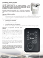
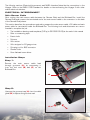
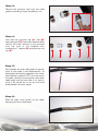
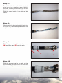
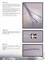
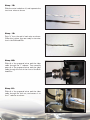
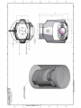
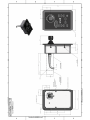
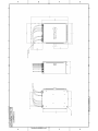
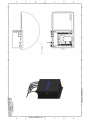
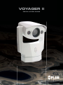
VOYAGER II
INSTALLATION GUIDE
1
© FLIR Systems, Inc., 2009. All rights reserved worldwide. No parts of this manual, in whole or in part,
may be copied, photocopied, translated, or transmitted to any electronic medium or machine readable
form without the prior written permission of FLIR Systems, Inc.
Names and marks appearing on the products herein are either registered trademarks or
trademarks of FLIR Systems, Inc. and/or its subsidiaries. All other trademarks, trade names, or
company names referenced herein are used for identification only and are the property of their
respective owners.
This product is protected by patents, design patents, patents pending, or design patents pending.
The Voyager II imaging system is controlled by US export laws. There are special versions of this system
that are approved for international distribution and travel. Please contact FLIR Systems if you have any
questions.
FLIR Systems, Inc.
70 Castilian Drive
Goleta, CA 93117
Phone: +1.888.747.FLIR (+1.888.747.3547)
www.flir.com
Document Number: 432-0002-00-11, rev 110
Document History
Revision
100
110
Date
Feb 2008
Jan 2009
Comment
Initial Release
Voyager II: includes NMEA interface, updated drawings, added TOC
and page numbers, other minor changes
This document is controlled to FLIR Technology Level 2. The information contained in this document
pertains to a dual use product controlled for export by the Export Administration Regulations (EAR).
FLIR trade secrets contained herein are subject to disclosure restrictions as a matter of law. Diversion
contrary to US law is prohibited. US Department of Commerce authorization is not required prior to
export or transfer to foreign persons or parties unless otherwise prohibited.
2
Contents
VOYAGER II INSTALLATION
4
Introduction
4
Installation Preparation
4
Prior to Cutting/Drilling Holes
4
PHYSICAL INSTALLATION
5
Voyager II Camera Body
5
Voyager II Bulkhead Box
5
Voyager II Joystick Control Unit (JCU)
5
ELECTRICAL INTERCONNECT
6
Main Sensor Cable
6
Installation Steps
6
NMEA INTERFACE
14
References
14
NMEA INTERFACE INSTALLATION
14
NMEA Installation Card
14
Connector Slot
14
NMEA Interface Wiring
15
Spare JCU Slot (1 or 2 JCUs in use)
15
Pigtail Connection (3 JCUs in use)
16
Electrical Checkout
16
Testing the NMEA Interface
17
DRAWINGS & INSTALLATION TEMPLATES
18
CONNECTIONS QUICK REFERENCE
18
3
VOYAGER II INSTALLATION
Introduction
Thank you for buying your new Voyager II! This manual describes the physical mounting and electrical
connection of the Voyager II camera. If you need help during the installation process, call 888.747.3547
to speak with one of FLIR’s Applications experts. The Voyager II should be installed by a qualified marine
electronics technician, as incorrect installation could void the warranty.
The Voyager II comes with these standard components:
•
Camera Body
•
Bulkhead Box
•
NMEA Interface Board (in a separate bag inside the Bulkhead Box)
•
50’ or 100’ main sensor cable
the Camera Body to the Bulkhead Box
•
Joystick Control Unit (JCU) with 100’ cable that connects to the Bulkhead Box
•
System Power cable (10’)
•
Voyager Documentation Package
(depending
on
what
you
ordered)
-
connects
You may need to supply:
•
16- gauge electrical wire; up to 100’ (3-conductor, for system power)
•
Six (6) ¼-20 stainless steel bolts for attaching the Voyager II Camera Body. Note that bolt
length may be dependant on mounting platform thickness
•
Four (4) bolts or screws for attaching the Bulkhead Box as required
•
Miscellaneous electrical hardware, connectors and tools
If using the NMEA interface features, you will need to provide a 2-wire serial cable to the Bulkhead
Box from your NMEA device.
Installation Preparation
•
Find a good place to mount the Voyager II’s components:
o
Mount the Voyager II as high as practical, but without interfering with any radar,
navigational or communications electronics, and minimizing the degree to which
vessel structures block the camera’s view.
o
Mount the Voyager II as close to the vessel’s centerline as possible so you will have
a symmetrical view of on-coming traffic.
o
Voyager II should be mounted on a flat surface with the base on the bottom and the
camera on top. Do not hang the Voyager II upside down; the picture will display
upside down, and you may damage the Voyager II.
Prior to Cutting/Drilling Holes
•
Once
the
mounting
location
has
sides of the mounting surface are accessible.
•
Determine if any interior trim panels must be removed in order to gain access to the
mounting hardware, and remove them ahead of time.
•
When selecting a mounting location for the Voyager II, consider cable lengths and routing. Ensure
the cables are long enough, given the proposed mounting locations and cable routing requirements, and route the cables before you install the components.
4
been
selected,
verify
both
PHYSICAL INSTALLATION
Voyager II Camera Body
Using the template supplied with this Installation Manual as a guide,
mark the location of the holes for mounting the Voyager II. Make sure the
template is aligned so that the Voyager II will point straight ahead, and that
the cable will exit towards the stern of the vessel.
Mount the Voyager II’s camera body with 6 1/4x20 bolts and washers.
There is also a 3/8x16 center insert which can be used for added support.
Voyager II Bulkhead Box
NOTE:
FLIR recommends that you terminate all cable ends inside the Bulkhead Box BEFORE you mount
it. Refer to the section on detailed cable preparation and termination for these instructions.
Mount the Bulkhead Box in an area that:
•
Is sheltered from the weather
•
Has good airflow
•
Is not exposed to direct sunlight
•
Is within easy reach of all required cables
•
Provides room for adequate service loops as depicted in the installation drawings supplied
Voyager
(JCU)
II
Joystick
Control
Unit
Mount the JCU in a convenient area that is close
to the monitor that will display the Voyager II video
output. Make sure the area you choose will leave
enough room for the connector and cable under
the JCU (refer to the drawing package supplied for
dimensions).
Using the template supplied with the Installation
Manual as a guide, mark the locations of the holes to
be cut and drilled for the JCU.
Cut the hole that will allow the JCU to be recessed
in the vessel’s control console per the installation
drawings supplied, and drill the holes for the four
mounting studs.
Route the JCU cable through the JCU munting hole.
Connect the terminated end of the cable to the JCU,
insert the JCU into its mounting location and secure
with the supplied mounting studs.
5
The following sections (Electrical Interconnect and NMEA Interface) describe the connections to the
Voyager. Refer to the NMEA 0183 Standard for details on interconnecting the Voyager II with other
marine electronic devices.
ELECTRICAL INTERCONNECT
Main Sensor Cable
After routing the main sensor cable between the Camera Body and the Bulkhead Box, install the
Camera Body and connect the terminated end of the main sensor cable to the connector on the back
of the Camera Body’s base.
This section describes the procedures required to prepare the main sensor cable, JCU cable and main
power cable for termination inside the Bulkhead Box. The following tools and documents are recommended to complete the job:
•
The installation drawings and templates (FLIR p/n 432-0002-00-19) at the end of this manual
•
Ruler or measuring tape
•
Exacto knife
•
Scissors
•
Wire cutter
•
Wire stripper for 20 gauge wires
•
Crimping tool for BNC connector
•
Channel locks
•
2mm flathead screw driver
Installation Steps
Step 1:
Remove the main sensor cable feed
through grommet (A) by unscrewing it
from the lock nuts (B) and (C) on the
Bulkhead Box.
C
A
B
Step 2:
Unscrew the grommet cap (A) from the cable
gland (B) to expose the grommet seal
A
6
B
Step 3:
Remove the grommet seal from the cable
gland by inserting a finger and pulling it out.
Step 4:
Now that the grommet cap (A), seal (B),
and cable gland (C) have been disassembled,
remove the other sections of the grommet
from the front of the Breakout Box,
including the 1” reducer (D), and the inner lock
nut (E).
A
Step 5:
Now prepare the main cable ends for attachment to the inside of the Bulkhead Box. As
directed by the drawing supplied in this Installation Manual, measure 13.5” from the end of
the cable, carefully cut around the outer black
cable jacket until you can slide it off, and remove it. Be careful not to cut into the metal
braid beneath the outer jacket.
Step 6:
Slide the black outer jacket off the cable,
exposing the inner metal braid
7
B
C
D
E
Step 7:
Push the braid back over the black outer jacket an inch or two, creating an area of slack in
the braid. Carefully insert scissor tips into the
braid, and cut all the way around it as shown.
Slide the excess braid off the cable and discard it
Step 8:
Working with the shorter length of braid, trim
it so that only 1” extends beyond the black outer jacket as shown.
Step 9:
Slide the grommet cap (A – not shown), seal
(B), and cable gland (C) over the cable
A
B
C
Step 10:
Slide the grommet seal up the cable so that
the front edge just lines up with the end of the
black outer cable jacket as shown
8
Step 11:
Carefully fold the metal braid back over the
grommet seal as shown
Step 12:
Trim the metal braid as shown, so that the
black o-ring seal is clear of the metal braid.
Step 13:
Slide the cable gland over the grommet seal
as shown, capturing the metal braid between
the two
Step 14:
Screw the grommet cap onto the cable gland
as shown.
You are now ready to prepare the cable ends
for connection to the Bulkhead Box’s internal
termination blocks
9
Step 15:
Trim the clear Mylar sheath back so the individual wire bundles can be spread apart
as shown. This will make them easier to
identify and work with.
Cut the blue Ethernet cable to 12.5” long, measured from the end of the cable gland.
Cut the wire bundle inside a clear jacket and
steel braid to measure 11.5” long.
Cut the bundle of 4 twisted pairs inside a white
outer jacket to measure 11.5” long.
The video cable should be cut to 9.5”
Step 16:
Prepare the video cable by securing the crimpable 75-ohm BNC connector (provided) onto
the RG-179 cable.
Step 17:
The rest of the wires will need to be
prepared in a fashion similar to the following
progression.
Carefully cut around the outer insulation as
shown.
10
Step 18:
Slide the outer insulation off, and separate the
two inner wires as shown
Step 19:
Strip ¼” from the end of each wire as shown.
When this is done, they are ready for termination in the Bulkhead Box.
Step 20:
Slide all of the prepared wires and the video
cable through the 1” reducer. Then carefully
pass all of the prepared wires and the video
cable through the hole in the front of the Bulkhead Box.
Step 21:
Slide all of the prepared wires and the video
cable through the lock nut, and secure it to
the 1” reducer as shown
11
Step 22:
Connect the wires from the main sensor cable
to terminal blocks J6, J7, J8, and Video In
using the drawings provided at the end of this
manual for guidance.
Step 23:
Connect the wires from the system power
cable to J5. The cable ends are prepared
using the same procedures you used for
everything in the main sensor cable except the
video cable.
Step 24:
Connect the wires from the Joystick Control Unit (JCU) to the J1 terminal block.
The cable ends are prepared using the
same procedures used for the main sensor
cable.
Step 25:
Install additional (optional) JCUs and other connections as required to J2 - J4, as shown
on the next page.
When all wires have been connected,
mount the Bulkhead Box in the selected location.
12
J8
J4
J7
J3
J6
J2
J1
J5
13
NMEA INTERFACE
The Voyager II has the capability to “listen” to (or take commands from) radar, GPS or other devices
using the National Marine Electronics Association (NMEA) 0183 Protocol. The NMEA 0183 protocol
is a combined electrical and data specification for communication between marine electronic devices.
Additional information regarding the protocol can be found on the NMEA web site: http://www.nmea.
org/pub/0183/
According to the NMEA protocol, the Voyager II is known as a listener, and another device such as a
radar or multi-function display is known as a talker. This protocol allows the talker to send positional
information to the Voyager II camera, and it responds by automatically pointing toward vessels and
other objects that show up on the display and tracking their movement.
The Voyager II connects to the other equipment via a serial cable (not provided with the Voyager II).
The serial cable connects to the Voyager II through an unused Joystick Control Unit (JCU) slot on the
Voyager Bulkhead Box.
This document describes the steps necessary to install and verify the Voyager II NMEA 0183 interface. Operation of the Voyager II NMEA interface is described in the Voyager II User’s Guide Addendum.
References
• Voyager Installation Guide, FLIR Document Number: 432-0002-00-11
• National Marine Electronics Association, NMEA 0183 Version 2.0
Note, the Voyager II does not support the NMEA 0183-HS (High Speed) protocol
NMEA INTERFACE INSTALLATION
NMEA Installation Card
The Voyager II communicates with other devices through a custom interface card. The card is plugged
into one of the four JCU connector slots in the Bulkhead Box. The interface card has pigtail wires to
connect to the other NMEA device.
Figure 1: NMEA Interface Card
Connector Slot
The interface card comes installed in slot J4 by default. The card must be moved to the JCU slot
after the last active JCU. For a system with one JCU, the module should be plugged into the J2 slot;
for systems with 2 JCUs, the module must use the J3 slot (as pictured below). For a system with 3
JCUs, the module must use slot J4.
14
Figure 2: Bulkhead box JCU connection with NMEA card installed in Slot 3
NMEA Interface Wiring
The connection from the other NMEA device must be routed through one of the JCU cable glands located on the bottom wall of the Bulkhead Box.
Figure 3: Cable Glands on the Bulkhead Box
There are two methods for connecting the NMEA cable to the NMEA interface card. The first method
makes use of a spare JCU slot (in the case when only one or two JCUs are used); the second method
makes use of a pigtail connection when 3 JCUs are in use and the NMEA card occupies the 4th slot.
Spare JCU Slot (1 or 2 JCUs in use)
For a configuration that uses one or two JCUs and with the NMEA card plugged into the second or
third slot, the empty adjacent slot (J3 or J4, respectively) can be used to connect NMEA signals as
shown in Figure 4.
15
Figure 4: NMEA Interface card on Slot J3; NMEA connection in Slot J4
For this connection, attach NMEA “A” and “B” signal wires to connector terminals 1 and 2 respectively. These terminals are interconnected to the appropriate terminals in the previous slot within
the Bulkhead Box. No additional jumpers are necessary.
Pigtail Connection (3 JCUs in use)
For a Voyager II configuration with 3 JCUs and a NMEA interface, all four JCU slots are occupied.
The NMEA card will reside in the JCU slot J4. Route the NMEA interface cable up to the JCU slot
J4 and, using a cable tie, anchor the NMEA cable to the 3rd JCU cable. Cutoff the shrink wrap
insulator on the end of the wires and using in-line crimp splices and attach the NMEA talker signals
A and B to the pigtail red and yellow wires respectively.
Figure 5: NMEA Interface Card with Pigtail cable
Electrical Checkout
Disable the NMEA talker and verify the static RS-422 signal levels by measuring the voltage differ16
ence between the differential RS-422 outputs.
The voltage should be measured on the adjacent JCU; namely, if the module is plugged into JCU J3
slot, then the measurement should be on the connector residing in the JCU J2 slot.
Using a volt meter, measure the voltage difference from pin 8 (hot probe) and pin 9 (return probe of
the VOM). The voltage reading should be greater than +2.0V.
Pin 9
Pin 8
Figure 6: Voltage Test Points
Testing the NMEA Interface
Message Checkout
Refer to the user manual for the other NMEA device (the talker) for information on how to install the
connection and how to enable and control the NMEA messages it will generate.
Enable the NMEA talker and set the Baud Rate to 4800. Use the SETUP/NMEA menu and enable
RSD to allow the Voyager system to respond to the RSD message (refer to the Voyager II Operator’s
Manual Addendum for information on how to access the SETUP menu.) Next, get the NMEA talker
to generate an RSD message. For example, using the cursor on the multifunction display unit, move
the cursor and verify that the Voyager responds to the RSD message.
If the talker is configured to send only the cursor message, there may be delays due to packetizing
of the NMEA messages by the JCU. Under “normal” circumstances, a significant volume of other
NMEA messages are present and this allows good packetization that results in minimal delay.
17
CONNECTIONS QUICK REFERENCE
DRAWINGS & INSTALLATION TEMPLATES
The drawings provide more detailed dimensions and mounting information. If you have any
questions, call FLIR’s Applications Experts at 888.747.3547.
Use the templates to locate the holes required to mount the Voyager II’s Camera Body and JCU.
18
19
20
21
22
23
24
25
This page intentionally left mostly blank.
26
Caution: When you print this document from the .pdf file,
the installation templates may not be to scale. Be sure to
check the dimensions prior to cutting any holes.
27
This page intentionally left mostly blank.
28
Caution: When you print this document from the .pdf file,
the installation templates may not be to scale. Be sure to
check the dimensions prior to cutting any holes.
29
This page intentionally left mostly blank.
30
This page intentionally left mostly blank.
31
FLIR Systems, Inc.
CVS World Headquarters
70 Castilian Drive
Goleta, CA 93117
USA
PH + 1 805.964.9797
PH: + 1 877.773.3547 (Sales)
PH: + 1 888.747.3547 (Apps)
FX: + 1 805.685.2711
www.FLIR.com
FLIR Systems, Inc.
Corporate Headquarters
27700 SW Parkway Avenue
Wilsonville, OR 97070
USA
PH: + 1 877.773.3547
FX: + 1 503.498.3153
sales@flir.com
CVS Eurasian Headquarters
FLIR Systems CVS BV
Charles Petitweg 21
4847 NW Teteringen - Breda
The Netherlands
PH: +31 (0) 765.794194
FX: +31 (0) 765.794199
flir@flir.com
32
3
2