1
USER’S MANUAL
FX COMMUNICATION (RS-232C, RS485)
FX communication
Foreword
• This manual contains text, diagrams and explanations which will guide the reader in the correct installation and operation of the communication facilities of FX series. It should be read
and understood befre attempting to install or use the communication facilities of FX series.
• Further infomation can be found in the manual of each programmable controller.
• If in doubt at any stage of the installation of the communication facilities of FX series always
consult a professional electrical engineer who is qualified and trained to the local and
national standards which apply to the installation site.
• If in doubt about the operation or use of the communication facilities of FX series please
consult the nearest Mitsubisi Electric distributor.
• This manual is subject to change without notice.
FX communication
FX COMMUNICATION
(RS-232C, RS-485)
USER’S MANUAL
Manual number : JY992D69901
Manual revision : C
Date
: March 2000
Brand and product names describeed by/in this manual are trademarks or registered trademarks of the irrespective owners.
i
FX communication
ii
FX communication
FAX BACK
Mitsubishi has a world wide reputation for its efforts in continually developing and pushing
back the frontiers of industrial automation. What is sometimes overlooked by the user is the
care and attention to detail that is taken with the documentation. However,to continue this process of improvement, the comments of the Mitsubishi users are always welcomed. This page
has been designed for you,the reader,to fill in your comments and fax them back to us. We
look forward to hearing from you.
Fax numbers:
Your name ....................................................
Mitsubishi Electric....
.....................................................................
America
(01) 847-478-2283
Your company ..............................................
Australia
(02) 638 -7072
.....................................................................
Germany
(0 21 02) 486-1 12
Your location:................................................
South Africa
(0 27) 11 444-0223
.....................................................................
United Kingdom
(01707) 278-695
Please tick the box of your choice
What condition did the manual arrive in?
¨Good
¨Minor damage
Will you be using a folder to store the manual? ¨Yes
¨No
What do you think to the manual presentation?¨Tidy
¨Un-friendly
Are the explanations understandable?
¨Yes
¨Not too bad
¨Unusable
¨Unusable
Which explanation was most difficult to understand: ..................................................................
....................................................................................................................................................
Are there any diagrams which are not clear?
¨Yes
¨No
If so,which: ..................................................................................................................................
What do you think to the manual layout?
¨Good
¨Not too bad
¨Un-helpful
If there one thing you would like to see improved,what is it? ......................................................
....................................................................................................................................................
....................................................................................................................................................
Could you find the information you required easily using the index and/or the contents,if possible please identify your experience:............................................................................................
....................................................................................................................................................
....................................................................................................................................................
....................................................................................................................................................
....................................................................................................................................................
Do you have any comments in general about the Mitsubishi manuals? .....................................
....................................................................................................................................................
....................................................................................................................................................
....................................................................................................................................................
....................................................................................................................................................
Thank you for taking the time to fill out this questionnaire. We hope you found both the product
and this manual easy to use.
iii
FX communication
iv
FX communication
Guidelines for the Safety of the User and Protection of the programmable controllers
This manual provides information for the use of the FX series communication unit. The manual
has been written to be used by trained and competent personnel. The definition of such a person or persons is as follows;
a) Any engineer who is responsible for the planning, design and construction of automatic
equipment using the product associated with this manual should be of a competent
nature, trained and qualified to the local and national standards required to fulfill that
role. These engineers should be fully aware of all aspects of safety with regards to automated equipment.
b) Any commissioning or service engineer must be of a competent nature, trained and qualified to the local and national standards required to fulfill that job. These engineers
should also be trained in the use and maintenance of the completed product. This
includes being completely familiar with all associated documentation for the said product. All maintenance should be carried out in accordance with established safety practices.
c) All operators of the completed equipment should be trained to use that product in a safe
and coordinated manner in compliance to established safety practices. The operators
should also be familiar with documentation which is connected with the actual operation
of the completed equipment.
Note : Note: the term ‘completed equipment’ refers to a third party constructed device which
contains or uses the product associated with this manual.
Notes on the Symbols Used in this Manual
At various times through out this manual certain symbols will be used to highlight points of
information which are intended to ensure the users personal safety and protect the integrity of
equipment. Whenever any of the following symbols are encountered its associated note must
be read and understood. Each of the symbols used will now be listed with a brief description of
its meaning.
Hardware Warnings
1) Indicates that the identified danger WILL cause physical and property damage.
2) Indicates that the identified danger could POSSIBLY cause physical and property
damage.
3) Indicates a point of further interest or further explanation.
Software Warnings
4) Indicates special care must be taken when using this element of software.
5) Indicates a special point which the user of the associate software element should
be aware of.
6) Indicates a point of interest or further explanation.
v
FX communication
• Under no circumstances will Mitsubishi Electric be liable responsible for any consequential
damage that may arise as a result of the installation or use of this equipment.
• All examples and diagrams shown in this manual are intended only as an aid to understanding the text, not to guarantee operation. Mitsubishi Electric will accept no responsibility for
actual use of the product based on these illustrative examples.
• Owing to the very great variety in possible application of this equipment, you must satisfy
yourself as to its suitability for your specific application.
vi
FX communication
Table of Contents
Guideline of Safety ..........................................................................................v
1. Introduction ............................................................................................. 1-1
1.1 Communication Types ...........................................................................................1-1
1.2 System Configuration ............................................................................................1-2
1.2.1 N:N Network.............................................................................................................................. 1-2
1.2.2 Parallel Link .............................................................................................................................. 1-2
1.2.3 Computer Link........................................................................................................................... 1-3
1.2.4 No Protocol Communication .................................................................................................... 1-4
1.3 Supporting Function and Version .........................................................................1-4
2. Wiring ...................................................................................................... 2-1
2.1 Caution ..................................................................................................................2-1
2.1.1 Common .................................................................................................................................. 2-1
2.1.2 FX2N-485-BD ........................................................................................................................... 2-1
2.1.3 FX0N-485ADP .......................................................................................................................... 2-2
2.1.4 FX2-40AW................................................................................................................................. 2-2
2.2 Using RS232C Interface ........................................................................................2-3
2.2.1 Using RS Instruction or Computer Link..................................................................................... 2-3
2.2.2 Using FX2N-232IF ..................................................................................................................... 2-4
2.3 Using RS485 Interface...........................................................................................2-6
2.3.1 Selection of Wiring .................................................................................................................... 2-6
2.3.2 Terminal Resistor...................................................................................................................... 2-6
2.3.3 One-pair Wiring ........................................................................................................................ 2-7
2.3.4 Two-pair Wiring ........................................................................................................................ 2-8
2.4 Parallel Link ...........................................................................................................2-9
2.4.1 FX2N(1N)-485-BD and FX0N-485ADP........................................................................................ 2-9
2.4.2 Only FX0N-485ADP................................................................................................................. 2-10
2.4.3 FX2N(1N)-485-BD and FX2N(1N)-485-BD ................................................................................. 2-11
2.4.4 Only FX2-40AW ..................................................................................................................... 2-12
2.4.5 FX2-40AP .............................................................................................................................. 2-12
3. Specifications .......................................................................................... 3-1
3.1 Specifications of Communication ..........................................................................3-1
3.2 Communication Time.............................................................................................3-2
3.2.1 N:N network ............................................................................................................................. 3-2
3.2.2 Parallel link ............................................................................................................................... 3-2
3.2.3 Computer link............................................................................................................................ 3-3
vii
FX communication
4. N:N Network............................................................................................ 4-1
4.1 Related Flags and Data Registers.........................................................................4-1
4.1.1 Auxiliary Relays ....................................................................................................................... 4-1
4.1.2 Data Registers ......................................................................................................................... 4-2
4.2 Setting....................................................................................................................4-3
4.2.1 Setting the Station No. (D8176) ................................................................................................ 4-3
4.2.2 Setting the Total Number of Slave Stations (D8177) ............................................................... 4-3
4.2.3 Setting the Refresh Range (D8178).......................................................................................... 4-4
4.2.4 Setting Retry Count (D8178)..................................................................................................... 4-5
4.2.5 Setting Comms Time-out (D8179) ............................................................................................ 4-5
4.2.6 Program Used for Setting ........................................................................................................ 4-6
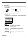
4.3 Example Program ..................................................................................................4-7
4.3.1 System Configuration ............................................................................................................... 4-7
4.3.2 Operations ................................................................................................................................ 4-7
4.3.3 Example of Setting Program ..................................................................................................... 4-8
4.3.4 Example of Error Program ....................................................................................................... 4-8
4.3.5 Example of Operation Program ................................................................................................ 4-9
5. Parallel link.............................................................................................. 5-1
5.1 Related Flags and Data Registers ........................................................................5-1
5.2 Mode and Link Device ...........................................................................................5-2
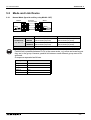
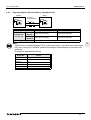
5.2.1 Normal Mode (Special auxiliary relay M8162: OFF) ................................................................ 5-2
5.2.2 High Speed Mode (Special auxiliary relay M8162: ON) ........................................................... 5-3
5.3 Example Program ..................................................................................................5-4
5.3.1 Normal Mode ............................................................................................................................ 5-4
5.3.2 High Speed Mode ..................................................................................................................... 5-4
6. Communication format (D8120) .............................................................. 6-1
6.1 What Is Communication Format ? .........................................................................6-1
6.2 Related Flags and Data Registers.........................................................................6-1
6.2.1 Special Auxiliary Relays ........................................................................................................... 6-1
6.2.2 Special Data Registers ............................................................................................................ 6-1
6.3 Communication Format (D8120) ..........................................................................6-2
6.4 Example of setting program...................................................................................6-3
viii
FX communication
7. Computer Link......................................................................................... 7-1
7.1 Data Flow by Link ..................................................................................................7-1
7.2 Information Needed Before Programming .............................................................7-3
7.2.1 Programmable Controller Operation ......................................................................................... 7-3
7.2.2 Notes of Computer.................................................................................................................... 7-3
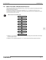
7.3 How to Read a Control Protocol Diagram..............................................................7-4
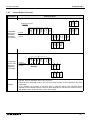
7.4 Basic Formats of Dedicated Protocol ....................................................................7-5
7.4.1 Control Protocol Format 1 ........................................................................................................ 7-6
7.4.2 Control Protocol Format 4......................................................................................................... 7-7
7.4.3 Control Protocol Parts Explained .............................................................................................. 7-8
7.4.4 Time- out Check Time............................................................................................................. 7-11
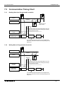
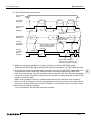
7.5 Communication Timing Chart ..............................................................................7-12
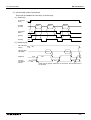
7.5.1 Reading Data from Programmable controller ......................................................................... 7-12
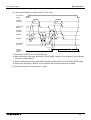
7.5.2 Writing Data to Programmable Controller ............................................................................... 7-12
7.5.3 Communication Time .............................................................................................................. 7-13
7.6 Character Area Data Transmission .....................................................................7-14
7.6.1 Bit Device Memory.................................................................................................................. 7-14
7.6.2 Word Device Memory ............................................................................................................. 7-15
7.7 Commands and Device Ranges ..........................................................................7-16
7.7.1 Commands.............................................................................................................................. 7-16
7.7.2 Device specification ranges .................................................................................................... 7-17
7.8 Example Computer Program for Loopback Test .................................................7-18
8. Commands.............................................................................................. 8-1
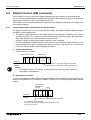
8.1 Batch Read of Bit Device (BR command)..............................................................8-2
8.2 Batch Read of Word Device (WR command) ........................................................8-3
8.3 Batch Write of Bit Device (BW command) .............................................................8-5
8.4 Batch Write of Word Device (WW command)........................................................8-6
8.5 Test of Bit Device (BT command)..........................................................................8-8
8.6 Test of Word Device (WT command) ....................................................................8-9
8.7 Remote RUN/STOP (RR, RS commands) ..........................................................8-10
8.7.1 Operation of Remote RUN/STOP ........................................................................................... 8-10
8.7.2 Conditions for Valid Execution of Remote RUN/STOP........................................................... 8-10
8.7.3 Control Specification and Examples of Remote RUN/STOP .................................................. 8-11
8.8 Reading The Programmable Controller Type (PC command).............................8-12
8.8.1 Type Codes ............................................................................................................................ 8-12
8.8.2 Control Specification and Example ......................................................................................... 8-13
8.9 Global Function (GW command) .........................................................................8-14
8.9.1 Control Specification and Example of Global Function........................................................... 8-14
8.10 On-demand Function .........................................................................................8-15
8.10.1 Special Devices Used in On-demand Function .................................................................... 8-15
8.10.2 On-demand Control Protocol ................................................................................................ 8-16
8.10.3 Specification and Example of On-demand............................................................................ 8-18
8.11 Loopback Test ...................................................................................................8-21
ix
FX communication
9. RS instruction.......................................................................................... 9-1
9.1 Function and Operation .........................................................................................9-1
9.1.1 Send and Receive Program...................................................................................................... 9-1
9.1.2 Operation of RS Instruction....................................................................................................... 9-2
9.1.3 Related Flags and Data Registers ............................................................................................ 9-3
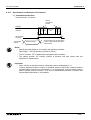
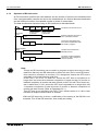
9.2 Hardware Hand Shake Operation..........................................................................9-5
9.2.1 FX, FX2C, FX0N, FX1S, FX1N and FX2N (earlier than V 2.00).................................................... 9-5
9.2.2 FX2N, FX2NC (V 2.00 or later) ................................................................................................... 9-9
9.3 Number of Communication Data .........................................................................9-12
9.3.1 Deal with 16 bits Data ............................................................................................................. 9-12
9.3.2 Deal with 8 bits Data ............................................................................................................... 9-13
9.4 Example Program ................................................................................................9-14
9.4.1 Personal Computer ................................................................................................................. 9-14
9.4.2 Printer ..................................................................................................................................... 9-16
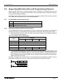
9.5 Supporting RS Instruction and Programming Protocol ........................................9-18
9.5.1 Programmable Controller and Version.................................................................................... 9-18
9.5.2 Operating Conditions and Format Set Content....................................................................... 9-18
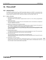
10. FX2N-232IF ......................................................................................... 10-1
10.1 Introduction ........................................................................................................10-1
10.1.1 Outline of Product ................................................................................................................. 10-1
10.2 Allocation of Buffer Memories (BFM’s) ..............................................................10-2
10.2.1 BFM List ............................................................................................................................... 10-2
10.2.2 Communication Format <BFM#0> ....................................................................................... 10-4
10.2.3 Command 〈BFM #1〉 .................................................................................................. 10−8
10.2.4 Receive Upper Limit Byte Count 〈BFM #2〉 ................................................................... 10−9
10.2.5 Receive Time-out Time <BFM #3> ....................................................................................... 10-9
10.2.6 Send Header <BFM #5 (upper), BFM #4 (lower)>................................................................ 10-9
10.2.7 Send Terminator <BFM #7 (upper), BFM #6 (lower)> .......................................................... 10-9
10.2.8 Receive Header <BFM #9 (upper), BFM #8 (lower)> ......................................................... 10-10
10.2.9 Receive Terminator <BFM #11 (upper), BFM #10 (lower)>................................................ 10-10
10.2.10 Receive Suspension Waiting Time <BFM #12> ............................................................... 10-10
10.2.11 Number of Remaining Send Data <BFM #13> ................................................................. 10-11
10.2.12 Number of Receive Buffers <BFM #14> ........................................................................... 10-11
10.2.13 Send Sum Result <BFM #15> .......................................................................................... 10-11
10.2.14 Receive Sum Result <BFM #16>...................................................................................... 10-11
10.2.15 Time from CS ON to Send Start <BFM #20>.................................................................... 10-12
10.2.16 Time from Completion of Actual Send to RS OFF (completion flag ON) <BFM #21> ...... 10-12
10.2.17 Status <BFM #28> ........................................................................................................... 10-13
10.2.18 Error Code <BFM #29>..................................................................................................... 10-14
10.2.19 Model Code <BFM #30>................................................................................................... 10-14
10.2.20 Send Byte Count <BFM #1000> ....................................................................................... 10-14
10.2.21 Send Buffers <BFMs #1001 to #1256>............................................................................. 10-14
10.2.22 Receive Byte Count <BFM #2000> .................................................................................. 10-15
10.2.23 Receive Buffers <BFM #2001 to #2256>.......................................................................... 10-15
10.2.24 Spare Receive Buffers for Interlink Connection Mode <BFM #2257 to #2271> ............... 10-15
10.3 Hardware Hand Shake Operation....................................................................10-16
10.3.1 No Hardware Hand Shake .................................................................................................. 10-16
10.3.2 Standard RS232C Mode..................................................................................................... 10-17
10.3.3 Interlink Mode ..................................................................................................................... 10-18
10.4 Example Program ............................................................................................10-19
10.4.1 Example of 16 Bits Data Communication ........................................................................... 10-19
10.4.2 Example of 8 Bits Data Communication ............................................................................. 10-23
x
FX communication
11. Optional Programming Port................................................................. 11-1
11.1 FX2N-422-BD, FX1N-422-BD...............................................................................11-1
11.2 FX2N-232-BD FX1N-232BD and FX0N-232ADP...................................................11-2
11.2.1 Connection cables ................................................................................................................ 11-2
11.3 Cautions on Use ................................................................................................11-3
11.3.1 Cautions on Setting............................................................................................................... 11-3
11.3.2 Cautions on use ................................................................................................................... 11-3
12. Diagnostics.......................................................................................... 12-1
12.1 Common Items ..................................................................................................12-1
12.2 N:N Network ......................................................................................................12-2
12.2.1 Error Code ............................................................................................................................ 12-2
12.2.2 Diagnostics ........................................................................................................................... 12-2
12.3 Parallel Link .......................................................................................................12-3
12.3.1 Diagnostics ........................................................................................................................... 12-3
12.4 Computer Link ...................................................................................................12-4
12.4.1 NAK Error Code .................................................................................................................... 12-4
12.4.2 Programmable Controller Error Code ................................................................................... 12-4
12.4.3 Diagnostics ........................................................................................................................... 12-5
12.5 RS Instruction ....................................................................................................12-6
12.5.1 Diagnostics ........................................................................................................................... 12-6
12.6 FX2N-232IF.........................................................................................................12-7
12.6.1 Error code ............................................................................................................................. 12-7
12.6.2 Diagnostics ........................................................................................................................... 12-7
12.7 Using Optional Programming Port .....................................................................12-8
12.7.1 FX1S, FX1N and FX2N(C) earlier V2.00 .................................................................................. 12-8
12.7.2 FX2N, FX2NC whose version is V 2.00 or later ...................................................................... 12-8
Appendix A:
Further Information Manual List ........................................................................... A-1
Appendix B:
ASCII code Lists................................................................................................... B-1
xi
FX communication
xii
FX Series Programmable Controllers
1
Introduction
2
Wiring
3
Specifications
4
N:N network
5
Parallel link
6
Communication format (D8120)
7
Computer link
8
Commands (for computer link)
9
RS instruction
10
FX2N-232IF
11
Optional programming port
12
Diagnostics
A
Further Information Manual List
B
ASCII code Lists
Introduction 1
1
FX Series Programmable Controllers
Introduction 1
FX communication
1.
Introduction 1
Introduction
1
1.1
Communication Types
The FX Series supports the fllowing 5 types of communication.
1 ) N:N network
Data transfer with FX2N, FX2NC, FX1N, FX 1S, FX0N programmable controllers can be performed on the N:N basis. They can link data of a small-scale system if using this network.
For system configuration refer to subsection 1.2.1, specifications refer to chapter 3, wiring
refer to chapter 2, settings, the number of transferred data and example program refer to
chapter 4,diagnostics refer to chapter 12.
2 ) Parallel link
Data transfer with FX2N, FX2NC, FX1N, FX and FX2C programmable controllers can be performed on a 1:1 basis for 100 auxiliary relays and 10 data registers. With FX1S and FX0N data
transfer is performed for 50 auxiliary relays and 10 data registers.
For a system configuration refer to Subsection 1.2.2, specifications refer to chapter 3, wiring
refer to chapter 2, the setting and example program refer to chapter 5, diagnostics refer to
chapter 12.
3 ) Computer link (Data transfer using dedicated protocol)
Data transfer with RS485 (422) units can be performed on a 1:n (16) basis using the dedicated protocol.
For system configuration refer to subsection 1.2.3, specifications refer to chapter 3, wiring
refer to chapter 2, setting of communication format refer to chapter 6, dedicated protocol
refer to chapter 7 & 8, diagnostics refer to chapter 12.
4 ) No protocol communication (Data transfer using RS instruction)
Data communication with a diversified RS232C unit including personal computers, bar code
readers and printers can be performed using no protocol communications.
This communication uses RS instruction’s or an FX2N-232IF special function block.
For system configuration refer to subsection 1.2.3, specifications refer to chapter 3, wiring
refer to chapter 2, setting of communication format, RS instruction and example program
refer to chapter 6 and 9, diagnostics refer to chapter 12.
When using the RS instruction, for setting the communication format refer to chapter 6, for
the RS instruction and example program please refer to chapter 9. Or when using an FX2N232IF, for setting and example program please refer to chapter 10.
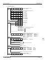
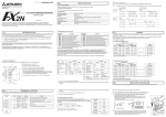
5 ) Optional programming port
The port can support a programming protocol, if connected to an FX2N-232-BD, FX0N-32ADP,
FX1N-232-BD, FX2N-422-BD and FX1N-422-BD for FX2N, FX2NC, FX1N, FX1S Series programmable controller.
For notes on use, refer to chapter 11, diagnostics refer to chapter 12.
1-1
Introduction 1
FX communication
1.2
System Configuration
For programming protocol refer to chapter 11.
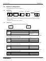
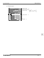
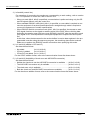
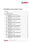
1.2.1
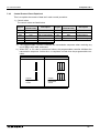
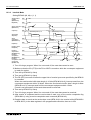
N:N Network
FX2N-CNV-BD
FX2N
FX0N-485ADP
FX2N-485-BD
FX0N,
FX2NC
FX2N
FX1N-485-BD
FX1N-CNV-BD
FX1S,
FX1N
FX1S,
FX1N
FX0N-485ADP
FX0N-485ADP
When not using FX2N-485-BD or FX1N-485-BD in the system, total extension distance Max. 500m.
(Use : Max. 50m)
Total station of this network is Max. 8 stations.
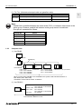
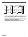
1.2.2
Parallel Link
①
②
1 ) FX2N, FX2NC (Shielded twisted-pair cable)
•, ‚
FX2N
FX2NC
Using interface
FX2N-485-BD
Extension distance
Max. 50 m
FX2N-CNV-BD + FX0N-485ADP
Max. 500 m
FX0N-485ADP
*1
*1 When including FX2N-485-BD in system configuration, total extension distance max 50m.
2 ) FX1N (Shielded twisted-pair cable)
•, ‚
FX1N
Using interface
Extension distance
FX1N-485-BD
Max. 50 m
FX1N-CNV-BD + FX0N-485ADP
Max. 500 m
*2
*2 When including FX1N-485-BD in system configuration, total extension distance max 50m.
3 ) FX1S (Shielded twisted-pair cable)
•, ‚
FX1s
Using interface
Extension distance
FX1N-485-BD
Max. 50 m
FX1N-CNV-BD + FX0N-485ADP
Max. 500 m
*3
*3 When including FX1N-485-BD in system configuration, total extension distance max 50m.
4 ) FX0N (Shielded twisted-pair cable)
•, ‚
FX0N
Using interface
FX0N-485ADP
Extension distance
Max. 500 m
1-2
Introduction 1
FX communication
5 ) FX, FX2C (Shielded twisted-pair cable and glassfiber cable)
•, ‚
FX2, FX2C
Using interface
1
Extension distance
FX2-40AW (Shielded twisted-pair cable)
Max. 10 m
FX2-40AP (Glassfiber cable)
Max. 50 m
Note;
Parallel link is possible between the same series PLC’s, or between other series in the
same group. However, parallel link between each group cannot be achieved.
Group’s are separated as follows.
Group No.
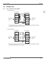
1.2.3
Series
Group 1
FX2N, FX2NC
Group 2
FX1N
Group 3
FX1S
Group 4
FX0N
Group 5
FX, FX2C
Computer Link
1 ) Use RS485
Computer
RS232C
RS485(422)
FX-485PC-IF
FX2,
FX2C
FX0N-485ADP
FX0N, FX2NC,
FX-485ADP
FX2N + FX2N-CNV-BD,
FX1S + FX1N-CNV-BD,
FX1N + FX1N-CNV-BD
FX2N + FX2N-485-BD, A series PLC + A(1S)J71UC24
FX1S + FX1N-485-BD,
FX1N + FX1N-485-BD
When not using FX2N-485-BD or FX1N-485-BD in the system, total extension distance is
Max. 500m. (Use : Max. 50m)
Total station of this network is Max. 16 stations.
2 ) Use RS232C
ž FX2N
Computer
ž FX2NC, FX0N
ž FX1N, FX1S
ž FX2, FX2C
: FX2N-232-BD,
FX2N-CNV-BD + FX0N-232ADP
: FX0N-232ADP
: FX1N-232-BD,
FX1N-CNV-BD + FX0N-232ADP
: FX-232ADP
Total extension distance is 15m.
1-3
Introduction 1
FX communication
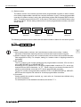
1.2.4
No Protocol Communication
RS232C
*3
Personal computer
*3
FX2N +
FX2N-232-BD
FX2N +
FX2N-CNV-BD
*3
FX2NC
FX0N-232ADP
FX0N-232ADP
*4
ž FX0N
ž FX1N +
FX1N-CNV-BD
ž FX1S +
FX1N-CNV-BD
*4
FX, FX2C
Max 15m *1
Bar code reader
FX-232ADP
*4
ž FX1N +
FX1N-232-BD
ž FX1S +
FX1N-232-BD
FX0N-232ADP
FX2N, FX1N,
FX2NC + FX2NC-CNV-IF
FX2N-232IF
RS485(422)
ž FX2N + FX2N-CNV-BD
ž FX1N + FX1N-CNV-BD
ž FX1S + FX1N-CNV-BD
ž FX0N, FX2NC
Printer
Max 500m *2
*4
*3
FX2N + FX2N-485-BD
FX0N-485ADP
*4
ž FX1N + FX1N-485-BD
ž FX1S + FX1N-485-BD
*1 RS485/RS232C signal convertor becomes necessary for a case of RS485 interface for computer connection.
*2 When using FX1N-485-BD, FX2N-485-BD in system, total extension distance max 50m.
But, RS485/RS232C signal convertor become necessary for a case of RS232C interface for
computer connection.
*3 This system configuration can achieve full-duplex communication or the half-duplex communication.
*4 This system configuration achieve only half-duplex communication.
1.3
Supporting Function and Version
Items
FX2N, FX2NC
FX1N, FX1S
N:N network
Parallel link
Computer link
Use RS instruction
No protocol
communication Use FX2N-232IF
All versions
All versions
FX0N
FX, FX2C
V2.00 or more
No sport
All versions
All versions
V1.20 or more
V3.30 or more
All versions
V3.00 or more
Not supported.
1-4
FX Series Programmable Controllers
1
Introduction
2
Wiring
3
Specifications
4
N:N network
5
Parallel link
6
Communication format (D8120)
7
Computer link
8
Commands (for computer link)
9
RS instruction
10
FX2N-232IF
11
Optional programming port
12
Diagnostics
A
Further Information Manual List
B
ASCII code Lists
Wiring 2
2
FX Series Programmable Controllers
Wiring 2
FX communication
2.
Wiring 2
Wiring
For the terminal layout when using a communication unit, refer to the individual units manual.
2.1
Caution
2.1.1
Common
2
1 ) This system is designed to read and write data (forced on/off) while the programmable controller is running.
If abnormal data is written into the programmable controller, due to effects of noise, the programmable controller may malfunction and cause machine trouble or an accident. Therefore, observe the following cautions.
• Do not lay signal cables near high voltage power cables or put them in the same trunking
duct.
Otherwise effects of noise or surge induction are likely to take place. Keep a safe distance of more than 100 mm from these wires.
• Ground the shield wire or shield of a shielded cable at one point on the programmable
controller. Do not, however, ground at the same point as high voltage lines.
2 ) Cut off phases of power source externally, before installation or wiring work in order to avoid
electric shock or damage of product.
3 ) Replace the provided terminal cover before supplying power and operating the unit after
installation or wiring work in order to avoid electric shock.
2.1.2
FX2N-485-BD
To connect the RS485(422) unit, use a shielded twist-pair cable. The cable model must be
AWG 26 to 16, and the maximum tightening torque must be 0.6 Nžm (6 kgfžcm). If a cable other
than the AWG 26 to 16 is used, normal communication cannot be assured because the terminal may be imperfectly contacted. It is recommended to insert a cable integrated by a crimping
tool into the terminal.
6mm
2-1
Wiring 2
FX communication
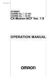
2.1.3
FX0N-485ADP
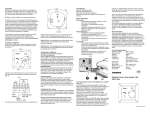
1 ) The terminal screws of the FX(0N)-485ADP are M3 screws and therefore the crimp style terminal (see drawing) suitable for use with these screws should be fitted to the cable for wiring.
6.2mm
(0.24 inches)
or less
For M3
6.2mm
(0.24 inches)
or less
For M3
2 ) The terminal tightening torque is 0.5 to 0.8 N⋅m(5 to 8 kgf⋅cm), tighten securely to avoid
malfunction.
2.1.4
FX2-40AW
1 ) The terminal screws for the terminal block of the FX2-40AW are M3.5 screws and therefore
the crimp style terminal (see drawing) suitable for use with these screws should be fitted to
the cable for wiring.
6.8mm
(0.27 inches)
or less
For M3.5
6.8mm
(0.27 inches)
or less
For M3.5
2 ) The terminal tightening torque is 0.5 to 0.8 N⋅m (5 to 8 kgf⋅cm), tighten securely to avoid malfunction.
2-2
Wiring 2
FX communication
2.2
Using RS232C Interface
Below is a typical wiring example. Please wire similar to the following pin name, when a pin number on the side of a counterpart machine differs.
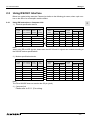
2.2.1
Using RS Instruction or Computer Link
2
1 ) Terminal specification device
P rogram m ab le C ontroller S ide
S ignal
nam e
F X 2N - 232-B D
F X 1N - 232-B D
FG
F X 0N 232A D P
-
R S -232C D e vice S ide
FX232A D P
S ignal
nam e
1
FG
U ses C S , R S
9-pin
25-pin
D -S U B D -S U B
1
S ignal
nam e
FG
U ses D R , E R
9-pin
25-pin
D -S U B D -S U B
1
R D (R X D )
2
3
R D (R X D )
2
3
R D (R X D )
2
3
S D (T X D )
3
2
S D (T X D )
3
2
S D (T X D )
3
2
E R (D T R )
4
20
RS RTS)
7
4
E R (D T R )
4
20
S G (G N D )
5
7
S G (G N D )
5
7
S G (G N D )
5
7
D R (D S R )
6
6
C S (C T S )
8
5
D R (D S R )
6
6
Note;
When using ER and DR signals, please also check if RS and CS signals are needed according to
the RS232C device specifications.
2 ) Modem specification device
P rogram m ab le C ontroller S ide
S ignal
nam e
F X 2N - 232-B D
F X 1 N - 232-B D
FG
F X 0N 232A D P
FX232A D P
-
C D (D C D )
1
R D (R X D )
2
R S -232C D e vice S ide
S ignal
nam e
U ses C S , R S
9-pin
25-pin
D -S U B D -S U B
1
S ignal
nam e
1
FG
8
C D (D C D )
1
8
FG
1
8
3
R D (R X D )
2
3
R D (R X D )
2
3
-
FG
U ses D R , E R
9-pin
25-pin
D -S U B D -S U B
1
S D (T X D )
3
2
S D (T X D )
3
2
S D (T X D )
3
2
E R (D T R )
4
20
RS RTS)
7
4
E R (D T R )
4
20
S G (G N D )
5
7
S G (G N D )
5
7
S G (G N D )
5
7
D R (D S R )
6
6
C S (C T S )
8
5
D R (D S R )
6
6
Note;
The FX0N-232ADP does not monitor the CD pin (pin8).
3 ) Computer link
Please refer to 2.2.1 1) for wiring.
2-3
Wiring 2
FX communication
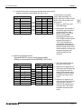
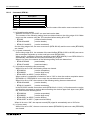
2.2.2
Using FX2N-232IF
The signal wiring of the RS232C equipment varies depending on the RS232C connection specifications. Check the specifications of the RS232C equipment used, then connect the signals correctly. Representative wiring examples are shown below.
1 ) Terminal specification device (No control line)
Setting communication format (BFM #0); b9=0, b8=0
P rogram m able C ontroller S id e
S ignal
F X 2N -232IF
nam e
S D (T X D )
3
R S -232C D evice S ide
S ignal
9-pin
25-pin
nam e
D -S U B D -S U B
S D (T X D )
3
2
R D (R X D )
2
R D (R X D )
2
3
S G (G N D )
5
S G (G N D )
5
7
Communication is performed in
accordance with the condition
determined by the software in
the FX2N-232IF and the counterpart equipment.
2 ) Terminal specification device (Use control line)
a ) Standard RS232C mode (Use cross cable)
Setting communication format (BFM #0); b9=0, b8=1
P rogram m able C ontroller S ide
S ignal
F X 2N -232IF
nam e
S D (T X D )
3
R S -232C D evice S ide
S ignal
9-pin
25-pin
nam e
D -S U B D -S U B
S D (T X D )
3
2
R D (R X D )
2
R D (R X D )
2
3
R S (R T S )
7
R S (R T S )
7
4
C S (C T S )
8
C S (C T S )
8
5
C D (D C D )
1
C D (D C D )
1
8
E R (D T R )
4
E R (D T R )
4
20
D R (D T R )
6
D R (D T R )
6
6
S G (G N D )
5
S G (G N D )
5
7
*1
*2
*1
*2
As the carrier to send (CS) signal pin of the FX2N-232IF itself
receives the request to send
(RS) signal, signal transfer is
performed as if the counterpart
equipment is functioning.
*1 When the CD signal is not
monitored, the CD signal pin
is not required to be connected. With regard to the
CD signal, the FX2N-232IF
only indicates the status.
*2 The FX2N-232IF only indicates the status.
2-4
Wiring 2
FX communication
b ) Interlink connection mode (Use interlink serial cross cable)
Setting connection format (BFM #0); b9=1, b8=1
In the interlink connection
P rogram m able C ontroller S ide
R S -232C D evice S ide
mode, data exceeding 512
S ignal
S ignal
9-pin
25-pin
bytes (upper limit of the receive
F X 2N -232IF
nam e
nam e
D -S U B D -S U B
buffer in the FX2N-232IF) can
S D (T X D )
3
S D (T X D )
3
2
be received.
R D (R X D )
2
R D (R X D )
2
3
R S (R T S )
7
R S (R T S )
7
4
C S (C T S )
8
C S (C T S )
8
5
E R (D T R )
4
E R (D T R )
4
20
D R (D T R )
6
D R (D T R )
6
6
S G (G N D )
5
S G (G N D )
5
7
*1
*2
*1
*2
*1 The FX2N-232IF only indicates the status.
*2 In this mode, the request to
send (RS) signal functions
as the signal to enable
receive in the FX2N-232IF.
When receiving data
exceeding 512 bytes, the
FX2N-232IF sets the request
to send (RS) signal to
“OFF” and requests the
counterpart equipment to
suspend the send operation.
When the data saved in the
receive buffers is read by the
sequence program, the
remaining data can be
received.
3 ) Modem specification device
Standard RS232C mode (Using straight cable)
Setting communication format (BFM #0); b9=0, b8=1
P rogram m able C ontroller S ide
S ignal
F X 2N -232IF
nam e
S D (T X D )
3
R S -232C D evice S ide
S ignal
9-pin
25-pin
nam e
D -S U B D -S U B
S D (T X D )
3
2
R D (R X D )
2
R D (R X D )
2
3
R S (R T S )
7
R S (R T S )
7
4
C S (C T S )
8
C S (C T S )
8
5
*1 C D (D C D )
1
8
E R (D T R )
4
20
C D (D C D )
1
E R (D T R )
4
D R (D T R )
6
S G (G N D )
5
C I (R I)
9
*1
*2
*3
*2
*3
D R (D T R )
6
6
S G (G N D )
5
7
C I (R I)
9
22
*1 The FX2N-232IF indicates
the status exclusively.
*2 When the CD signal is not
monitored, the CD signal pin
is not required to be connected. With regard to the
CD signal, the FX2N-232IF
indicates the status exclusively.
*3 When the CI signal is not
required, the CI signal pin is
not required to the connected. With regard to the
CI signal, the FX2N-232IF
indicates the status exclusively.
2-5
2
Wiring 2
FX communication
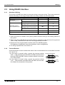
2.3
Using RS485 Interface
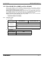
2.3.1
Selection of Wiring
The wiring of RS485 can either be one-pair wiring or two-pair wiring. The wiring method is
decided according to the usage. Please select the wiring method from the table below.
Usage
One-pair wiring
Two-pair wiring
¡
Full-duplex communication *3
l*2
×
It is necessary to set the
message wait in 70 ms or less.
×
¡
It is not necessary to set the
massage wait in 70 ms or less.
l*2
¡
¡
Parallel link *4
×
l
N:N network
¡
×
No protocol
(Use RS instruction) *1
Dedicated protocol
(Use computer link)*1
Half-duplex communication
Use on-demand function
¡
¡
l…Recommendation, ¡…OK, ×…Can not use
*1 When this product is added to the system, please match the wiring to the existing method of
the system.
*2 When using FX2N-485-BD with this wiring method, remember to take account of/or ignore the
“echo” of the commands sent from the FX2N programmable controller.
*3 Please use FX2N programmable controller and FX2N-485-BD together.
Full-duplex the combination cannot be achieved in other configurations.
*4 For wiring of parallel link, see section 2.4.
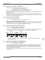
2.3.2
Terminal Resistor
A terminal resistor must be used at both ends of the communication line as described in section
2.3.3 and 2.3.4.
1 ) In the case of two-pair wiring, connect the terminal resister
(330Ω, 1/4W) between terminals SDA and SDB as well between
terminals RDA and RDB. Use the resistors offered as accessories of the product.
2 ) In the case of one-pair wiring, connect the terminal resister
(110Ω, 1/2W) between terminals RDA and RDB. Use the resistors offered as accessories of the product.
Orange Orange Brown
330 Ω
1/4 W
Brown Brown Brown
110 Ω
1/2 W
2-6
Wiring 2
FX communication
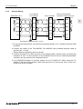
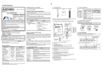
2.3.3
One-pair Wiring
RS485/422 unit *4
R*1
FX1N-485-BD
FX2N-485-BD
FX (0N)-485ADP
A series programmable
controller's computer link unit
R*1
SDA
SDA
SDB
SDB
SDB
SDB
RDA
RDA
RDA
RDA
RDB
RDB
RDB
RDB
SG
SG
LINK
SG *3
SG *3
FG
FG
SDA
SDA
2
R*1
*2
R*1
Grounding of registance 100 Ω or less
*1 R is the terminating resistor. Connect the terminating resistor (110Ω) between terminals SDA
and SDB.
*2 Connect the shield of the FX2N-485-BD, FX1N-485-BD using shielded twist-pair cable to
ground (100Ω or less).
Please adjust the grounding only to one side.
*3 Connect terminal FG to each terminal of the programmable controller body, grounded with
resistance of 100Ω or less. However, for the computer link unit of the A series programmable
controller, see the manual of the computer link unit.
*4 If an RS485/232 adapter is required, please use the FX-485-PC-IF. When using the FX485PC-IF with this wiring method, either take account for or ignore the “echo” of the commands sent by the computer.
2-7
Wiring 2
FX communication
2.3.4
Two-pair Wiring
RS485/422 unit *4
R*1
FX1N-485-BD
FX2N-485-BD
FX (0N)-485ADP
A series programmable
controller's computer link unit
R*1
SDA
SDA
SDA
SDA
SDB
SDB
SDB
SDB
RDA
RDA
RDA
RDA
RDB
RDB
RDB
RDB
SG
SG
LINK
SG
SG
FG*3
FG*3
R*1
*2
R*1
Grounding of registance 100 Ω or less
*1 R is the terminating resistor. Connect the terminating resistor (330Ω) between terminals SDA
and SDB, and terminals RDA and RDB.
*2 Connect the shield of FX2N-485-BD, FX1N-485-BD using shielded twist-pair cable to ground
(100Ω or less).
Please adjust the grounding only to one side.
*3 Connect terminal FG to each terminal of the programmable controller main body grounded
with resistance of 100 Ω or less. However, as for the computer link unit of the A series programmable controller, see the manual of the computer link unit.
*4 When using RS232/485 or RS232/422 adapter, please the adapter use FX-485PC-IF.
2-8
Wiring 2
FX communication
2.4
Parallel Link
2.4.1
FX2N(1N)-485-BD and FX0N-485ADP
1 ) One-pair Wiring
T erm inating
resistance
110Ω
F X 2N -485-B D
F X 1N -485-B D
F X 0N -485A D P
SDA
SDA
SDB
SDB
RDA
RDA
RDB
RDB
SG
LIN K
SG
2
T erm inating
registance
110Ω
F G *1
*1 Connect terminal FG to each terminal of the programmable controller main body,
grounded with resistance of 100Ω or less.
2 ) Two-pair Wiring
T erm inating
resistance
330Ω
F X 2N -485-B D
F X 1N -485-B D
F X 0N -485A D P
SDA
SDA
SDB
SDB
RDA
RDA
RDB
RDB
SG
LIN K
SG
T erm inating
registance
330Ω
F G *2
*2 Connect terminal FG to each terminal of the programmable controller main body,
grounded with resistance of 100Ω or less.
2-9
Wiring 2
FX communication
2.4.2
Only FX0N-485ADP
1 ) One-pair Wiring
T erm inating
resistance
110Ω
F X 0N -485A D P
F X 0N -485A D P
SDA
SDA
SDB
SDB
RDA
RDA
RDB
RDB
LIN K
SG
LIN K
SG
FG
F G *1
T erm inating
registance
110Ω
*1 Connect terminal FG to each terminal of the programmable controller main body,
grounded with resistance of 100Ω or less.
2 ) Two-pair Wiring
T erm inating
resistance
330Ω
F X 0N -485A D P
F X 0N -485A D P
SDA
SDA
SDB
SDB
RDA
RDA
RDB
RDB
LIN K
SG
LIN K
SG
FG
F G *2
T erm inating
registance
330Ω
*2 Connect terminal FG to each terminal of the programmable controller main body,
grounded with resistance of 100Ω or less.
2-10
Wiring 2
FX communication
2.4.3
FX2N(1N)-485-BD and FX2N(1N)-485-BD
1 ) One-pair Wiring
T erm inating
resistance
110Ω
F X 2N -485-B D
F X 1N -485-B D
F X 2N -485-B D
F X 1N -485-B D
SDA
SDA
SDB
SDB
RDA
RDA
RDB
RDB
SG
SG
F X 2N -485-B D
F X 1N -485-B D
F X 2N -485-B D
F X 1N -485-B D
SDA
SDA
SDB
SDB
RDA
RDA
RDB
RDB
SG
SG
2
T erm inating
registance
110Ω
2 ) Two-pair Wiring
T erm inating
resistance
330Ω
T erm inating
registance
330Ω
2-11
Wiring 2
FX communication
2.4.4
Only FX2-40AW
FX2-40AW
FX2-40AW
SA
SA
SB
SB
SG*1
SG*1
*1 SG Terminal of FX2-40AW connect to
SG terminal of FX or FX2C main unit.
*2 Please connect the shield of shielded
twist pair cable with
terminal to
which the programmable controller main
unit is grounded. Please adjust the
grounding only to one side.
*2
FX, FX2C main unit
2.4.5
FX2-40AP
FX2-40AP
FX2-40AP
T
R
R
T
Optical glassfiber
cable
Note;
• Keep optical fibers away from wire cables carrying high loads.
Including where the cables are terminated.
2-12
FX Series Programmable Controllers
1
Introduction
2
Wiring
3
Specifications
4
N:N network
5
Parallel link
6
Communication format (D8120)
7
Computer link
8
Commands (for computer link)
9
RS instruction
10
FX2N-232IF
11
Optional programming port
12
Diagnostics
A
Further Information Manual List
B
ASCII code Lists
Specifications 3
3
FX Series Programmable Controllers
Specifications 3
Specifications 3
FX communication
3.
Specifications
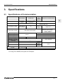
3.1
Specifications of Communication
N:N network
Transmission standard
Transmission distance
Connected the number
Communication method
Data length
Parity
Stop bit
Baud rate (bps)
Header character
Terminator character
Control line
Parallel link
Computer
link
(dedicated
protocol)
No protocol communication
Conforming to
RS485
Conforming to RS485
Conforming to RS485 and RS422 or RS232C
and RS422
RS485(RS422): Max. 500m
Max. 500m
RS232C: Max. 15m
1:N
RS232C:1:1
Total station is
1:1
(N is Max. 16
Max. 8 stations
RS485:1:N *1
stations
FX, FX2C, FX0N, FX1N, FX1S :
half-duplex communication
Half-duplex communication
FX2N, FX2NC*2: full-duplex
communication
7 bit / 8 bit
Fixation
None / Odd / Even
1 bit / 2bit
38,400
19,200
300/600/1,200/2,400/4,800/9,600/19,200
Fixation
None / effective
Protocol
Sum check
Fixation
Supported programmable
FX2N, FX2NC,
FX1N, FX1S, FX0N
controller
Format 1 /
Format 4
None /
effective
None
FX2N, FX2NC, FX1N, FX1S, FX0N, FX FX2C
*1 FX2N, FX2NC, FX1N, FX1S and FX0N supported.
*2 If using FX0N-485ADP, this system is half-duplex.
3-1
3
Specification 3
FX communication
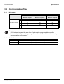
3.2
Communication Time
3.2.1
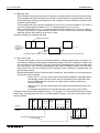
N:N network
Communication device
Total station number
2
3
4
5
6
7
8
Pattern 0
Bit device: 0 point
Word device: 4 points
18
26
33
41
49
57
65
Pattern 1
Bit device: 32 points
Word device: 4 points
22
32
42
52
62
72
82
Pattern 2
Bit device: 64 points
Word device: 8 points
34
50
66
83
99
115
131
Note;
If N:N network is used, the scan time of each station programmable controller
becomes about 10 percent longer regardless of the number of link station or using
communication device pattern.
3.2.2
Parallel link
Normal Mode
70 for reciprocation + Operation cycle of master station
+ Operation cycle of slave station (ms)
High speed mode
20 for reciprocation + Operation cycle of master station
+ Operation cycle of slave station (ms)
3-2
Specifications 3
FX communication
3.2.3
Computer link
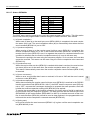
Calculations to determine the approximate time until communication is complete.
1 ) Programmable controller → Computer
Communication time = Number of total characters based on dedicated protocol*1
× Time to send or receive one character (ms)*2
+ Programmable controller’s maximum scan time (ms) × 3
+ Message wait (ms)
2 ) Computer → Programmable controller
3
Communication time = Number of total characters based on dedicated protocol*1
× Time to send or receive one character (ms)*2
+ Programmable controller’s maximum scan time (ms)
+ Message wait (ms)
*1 Please count the number of characters referring to section 7.4.1 and 7.4.2 and chapter 8.
*2 Please refer to the following expression for the method of calculating this time.
Time to send or receive one character = 1/baud rate × number of bits in character
(start bit(1) + Data length(7 or 8) + Parity bit(0 or 1) + Stop bit(1 or 2) )
Example
When 1 character = 10 bits (Data length = 7, Parity bit = 1, stop bit = 1 start bit = 1),
this time is as follows.
Baud rate (bps)
300
600
1200
2400
4800
9600
19200
Time to send or receive one character (ms)
33.34
16.67
8.34
4.17
2.08
1.04
0.52
Note;
Please refer to following table for the relation between reading word points and communication
time.
“Message time = 0ms, Maximum scan time = 20ms, Dedicated protocol format = format 1,
Command = WR, Baud rate = 9,600 or 19,200 bps”
Reading word points
10
32
64
Baud rate (bps)
9,600
0.3 s
0.4 s
0.5 s
19,200
0.2 s
0.3 s
0.4 s
3-3
Specification 3
FX communication
MEMO
3-4
FX Series Programmable Controllers
1
Introduction
2
Wiring
3
Specifications
4
N:N network
5
Parallel link
6
Communication format (D8120)
7
Computer link
8
Commands (for computer link)
9
RS instruction
10
FX2N-232IF
11
Optional programming port
12
Diagnostics
A
Further Information Manual List
B
ASCII code Lists
N:N network 4
4
FX Series Programmable Controllers
N:N network 4
N:N network 4
FX communication
4.
N:N Network
For diagnostics, please refer to chapter 12.
4.1
Related Flags and Data Registers
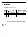
4.1.1
Auxiliary Relays
Auxiliary relays
Attribute
FX0N,
FX1S
R
FX1N, FX2N,
FX2NC
M8038
R
M504
M8183
R
M505 to
M511 *2
M8184 to
M8190 *2
R
M503
M8191
R : Ready only
W : Write only
Name
N:N network
parameter setting
Description
Used to set N:N network
parameters
Response
type
M, L
Communication error of When communication error is
L
master station
in master station, this is ON. *1
Communication error of When communication error is
slave station
in slave station, this is ON. *1
Data communication
M : Master station
When communicate to other
station, this is ON.
M, L
M, L
L : Slave station
*1 The number of communication errors that have occured in each station cannot be counted in
the CPU error status, the program error status or the stop status.
*2 No. in accordance with the slave station No.
Example: FX0N, FX1S……………Slave station No.1 is M505, Slave station No.2 is M506,
~ Slave station No.7 is M511.
FX2N, FX2N, FX1N……Slave station No.1 is M8184, Slave station No.2 is M8185,
~ Slave station No.7 is M8190.
Note;
• Devices M503 to M511 in the FX0N and FX1S cannot be applied for other usage in the
user program. These devices are used by the N:N network.
4-1
4
N:N network 4
FX communication
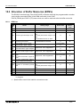
4.1.2
Data Registers
Auxiliary relays
Attribute
FX0N,
FX1S
Name
FX1N, FX2N,
FX2NC
Description
Response
type
R
D8173
Station No.
Saves its own station No. M, L
R
D8174
Total number of slave
stations
Saves total number of
slave stations
M, L
R
D8175
Refresh range
Saves refresh range
M, L
W
D8176
Station number setting
Sets its own station No.
M, L
W
D8177
Total slave station number
setting
Sets total number of
slave stations
M
W
D8178
Refresh range setting
Sets refresh range
M
W/R
D8179
Retry count setting
Sets retry count
M
W/R
D8180
Comms time-out setting
Sets comms time-out
M
M, L
R
D201
D8201
Current network scan time
Saves current network
scan time
R
D202
D8202
Maximum network scan
time
Saves maximum network
M, L
scan time
R
D203
D8203
Number of communication
error at master station
Number of communication error at master station *1
L
R
D204 to
D210 *2
D8204 to
D8210 *3
Number of communication
error at slave station
Number of communication error at slave station
*1
M, L
R
D211
D8211
Code of communication
error at master station
Code of communication
error at master station *1
L
R
D212 to
D218 *2
D8212 to
D8218 *3
Code of communication
error at slave station
Code of communication
error at slave station *1
M, L
D219 to
D255
Not used
For internal processing
R : Ready only
W : Write only
M : Master station
L : Slave station
*1 The number of communication errors occurred in its own station cannot be counted in the
CPU error status, the program error status or the stop status.
*2 No. in accordance with the slave station No.
Slave station No.1 is D204, D212, slave station No.2 is D205, D213,
… slave station No.7 is D210, D218.
*3 No. in accordance with the slave station No.
Slave station No.1 is D8204, D8212, slave station No.2 is D8205, D8213,
… slave station No.7 is D8210, D8218.
Note;
• Devices M503-M511 and D201-D255 in the FX0N and FX1S cannot be applied for other
usage in the user program. These devices are used by the N:N network.
4-2
N:N network 4
FX communication
4.2
Setting
Each settings for the N:N network become valid when the program is run or when the power of
the programmable controller is turned on.
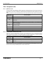
4.2.1
Setting the Station No. (D8176)
Set a value 0 to 7 to the special data register D8176.
Set value
0
1 to 7
4.2.2
Description
Master station
Slave station No.
Example: 1 is slave station No.1, 2 is slave station No.2
4
Setting the Total Number of Slave Stations (D8177)
Set a value 1 to 7 to the special data register D8177. (Default = 7)
This setting is not required for the slave station.
Set value
Description
1
1 slave station
2
2 slave stations
:
:
7
7 slave stations
4-3
N:N network 4
FX communication
4.2.3
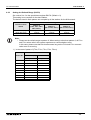
Setting the Refresh Range (D8178)
Set a value 0 to 2 to the special data register D8178. (Default = 0)
This setting is not required for the slave station.
The devices used in each pattern are occupied by all the stations for the N:N network.
Refresh range
Communication
device
Pattern 0
(FX0N, FX1S, FX1N,
FX2N, FX2NC)
Pattern 1
(FX1N, FX2N, FX2NC)
Pattern 2
(FX1N, FX2N, FX2NC)
Bit device (M)
0 point
32 points
64 points
Word device (D)
4 points
4 points
8 points
Note;
• Please set the refresh range to pattern 0. When setting it other than pattern 0, all FX0N
and FX1S series units in the system experience a communications error.
In this case, please note that link time becomes long as the FX0N and FX1S communication error is occurring.
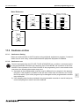
1 ) In the case of pattern 0 (FX0N, FX1S, FX1N, FX2N, FX2NC)
Device No.
Station No.
Bit device (M)
Word device (D)
0 point
4 points
No.0
D0 to D3
No.1
D10 to D13
No.2
D20 to D23
No.3
D30 to D33
No.4
D40 to D43
No.5
D50 to D53
No,6
D60 to D63
No.7
D70 to D73
4-4
N:N network 4
FX communication
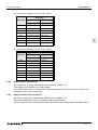
2 ) In the case of pattern 1 (FX1N, FX2N, FX2NC)
Device No.
Station No.
Bit device (M)
Word device (D)
32 points
4 points
No.0
M1000 to M1031 D0 to D3
No.1
M1064 to M1095 D10 to D13
No.2
M1128 to M1159 D20 to D23
No.3
M1192 to M1223 D30 to D33
No.4
M1256 to M1287 D40 to D43
No.5
M1320 to M1351 D50 to D53
No,6
M1384 to M1415 D60 to D63
No.7
M1448 to M1479 D70 to D73
4
3 ) In the case of pattern 2 (FX1N, FX2N, FX2NC)
Device No.
Station No.
4.2.4
Bit device (M)
Word device (D)
64 points
8 points
No.0
M1000 to M1063 D0 to D7
No.1
M1064 to M1127 D10 to D17
No.2
M1128 to M1191 D20 to D27
No.3
M1192 to M1255 D30 to D37
No.4
M1256 to M1319 D40 to D47
No.5
M1320 to M1383 D50 to D57
No,6
M1384 to M1447 D60 to D67
No.7
M1448 to M1511 D70 to D77
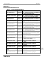
Setting Retry Count (D8178)
Set a value 0 to 10 to the special data register D8178. (Default = 3)
This setting is not required for the slave station.
If a master station tries to communicate with the slave station at this retry count (or over), communication error occur in the station.
4.2.5
Setting Comms Time-out (D8179)
Set value 5 to 255 to the special data register D8179. (Default = 5)
This value multiplied by 10(ms) is duration of the comms time-out.
Comms time-out is the communication dwell time between the master station and slave station.
4-5
N:N network 4
FX communication
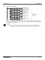
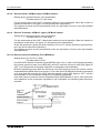
4.2.6
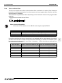
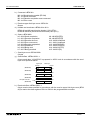
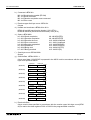
Program Used for Setting
0
M8038
FNC 12
MOV
K 0
D8176
Station No. setting:
Required for master
station (Set range: 0 to 7)
FNC 12
MOV
K 2
D8177
Total number of slave
stations: 2
(Setting range: 1 to 7)
FNC 12
MOV
K 1
D8178
Refresh range setting:
Pattern 1
(Set range: 1 to 2)
FNC 12
MOV
K 3
D8179
Refry count setting:
3 (3times)
FNC 12
MOV
K 6
D8180
Comms time-out setting:
6 (60ms)
Not required for
slave station
Make sure to write the program above from step 0 as the N:N network parameter setting program.
This program does not require to be executed, because it becomes effective automatically when it
is programmed in this position.
Note;
• Setting of the parameters for the N:N network is started at step 0 (LD M8038), and finished when any instruction or device other than the program above is processed.
4-6
N:N network 4
FX communication
4.3
Example Program
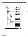
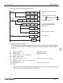
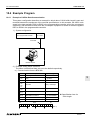
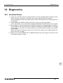
4.3.1
System Configuration
Master station (No.0)
FX 2N
4.3.2
Slave station (No.2)
FX 2N
FX 2N -485-BD
•
•
•
Slave station (No.1)
FX 2N -485-BD
FX 2N -485-BD
4
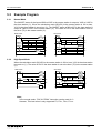
Refresh range: 32 bit devices and 4 word devices (Pattern 1)
Retry count: 3 times
Comms time-out: 5 (50 ms)
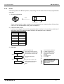
Operations
The following operations are performed in the system configuration above.
1 ) The input points X000 to X003 (M1000 to M1003) in the master station are output to the output points Y010 to Y013 in the stations Nos.1 and 2.
2 ) The input points X000 to X003 (M1064 to M1067) in the station No.1 are output to the output
points Y014 to Y017 in the master station and the station No.2.
3 ) The input points X000 to X003 (M1128 to M1131) in the station No.2 are output to the output
points Y020 to Y023 in the master station and the station No.1.
4 ) The data register D1 in the master station is specified as the set value of the counter C1 in
the station No.1.
The contact (M1070) status of the counter C1 is reflected on the output point Y005 in the
master station.
5 ) The data register D2 in the master station is specified as the set value of the counter C2 in
the station No.2.
The contact (M1140) status of the counter C2 is reflected on the output point Y006 in the
master station.
6 ) The value of the data register D10 in the station No.1 and the value of the data register D20
in the station No.2 are added in the master station, and saved to the data register D3.
7 ) The value of the data register D10 in the master station and the value of the data register
D20 in the station No.2 are added in the station No.1, and saved to the data register D11.
8 ) The value of the data register D10 in the master station and the value of the data register
D10 in the station No.1 are added in the station No.2, and saved to the data register D21.
4-7
N:N network 4
FX communication
4.3.3
Example of Setting Program
For the setting program of the master station and the stations Nos.1 and 2, refer to the program
below.
Master station Slave station No.1 Slave station No.2
0
4.3.4
Remarks
D8176
K0
K1
K2
Station No.
D8177
K2
Total slave station : 2 stations
D8178
K1
Refresh range : Pattern 1
D8179
K3
Retry count : 3 times (default)
D8180
K5
Comms time-out : 50 ms (default)
M8038
FNC 12
MOV
K 0
D8176
Station No. setting:
Required for master
station (Set range: 0 to 7)
FNC 12
MOV
K 2
D8177
Total number of slave
stations: 2
(Setting range: 1 to 7)
FNC 12
MOV
K 1
D8178
Refresh range setting:
Pattern 1
(Set range: 1 to 2)
FNC 12
MOV
K 3
D8179
Refry count setting:
3 (3times)
FNC 12
MOV
K 5
D8180
Comms time-out setting:
5 (50ms)
Not required for
slave station
Example of Error Program
Master communication error
M8183
Y000
Slave 1 communication error
M8184
Y001
Slave 2 communication error
M8185
Y002
*
*
*
Data communication
M8191
Y003
Continued to a), b) or c) in "4.3.5 Program".
* A station cannot recognise its own error. An error program for each station is not necessary.
4-8
N:N network 4
FX communication
4.3.5
Example of Operation Program
a ) Program of master station
RUN monitor
M8000
MOV
K1X000 K1M1000
Operation 1)
Slave 1
communication error
M8184
MOV
K1M1064 K1Y014
Operation 2)
MOV
K1M1128 K1Y020
Operation 3)
Slave 2
communication error
M8185
4
Slave 1
communication error
M8184
MOV
K 10
D 1
Operation 4)
Contact of slave 1 C1
device
M1070
Y005
Slave 2
communication error
M8185
MOV
K 10
D 2
Contact of slave 2 C2
device
M1140
Operation 5)
Y006
Slave 1
communication
error
M8184
Slave 2
communication
error
M8185
MOV
K 10
D 3
Operation 6)
MOV
K 10
D 0
Operation 7), 8)
END
4-9
N:N network 4
FX communication
b ) Program of slave station No.1
Counter reset
X001
RST
C 1
Master
communication
error
M8183
MOV
MOV
K1M1000 K1Y010
K1X000 K1M1064
Operation 1)
Operation 2)
Slave 2
communication
error
M8185
MOV
K1M1128 K1Y020
Operation 3)
Counter input
X000
C1
D1
C1
Y005
Operation 4)
M1070
Slave 2
Contact of
communication slave 2 C2
error
device
M1140
M8185
Y006
Slave 2
communication
error
M8185
ADD
Operation 5)
MOV
K 10
D 10
Operation 6), 8)
D 0
D 20
D 11
Operation 7)
END
4-10
N:N network 4
FX communication
c ) Program of slave station No.2
Counter reset
X001
RST
C 2
Master
communication
error
M8183
MOV
K1M1000 K1Y010
Operation 1)
MOV
K1M1064 K1Y014
Operation 2)
Slave 1
communication
error
M8184
MOV
K1X000 K1M1128
Operation 3)
Y005
Operation 4)
4
Slave 1
Contact of
communication slave 1 C1
error
device
M1070
M8184
Counter input
X000
C2
D2
C2
Y006
Operation 5)
M1140
MOV
K 10
D 20
D 0
D 10
D 21
Operation 6), 7)
Slave 1
communication
error
M8184
ADD
END
4-11
N:N network 4
FX communication
MEMO
4-12
FX Series Programmable Controllers
1
Introduction
2
Wiring
3
Specifications
4
N:N network
5
Parallel link
6
Communication format (D8120)
7
Computer link
8
Commands (for computer link)
9
RS instruction
10
FX2N-232IF
11
Optional programming port
12
Diagnostics
A
Further Information Manual List
B
ASCII code Lists
Parallel link 5
5
FX Series Programmable Controllers
Parallel link 5
Parallel link 5
FX communication
5.
Parallel link
Data transfer with FX2N, FX2NC, FX1N, FX, FX2C programmable controllers can be performed on a
1:1 basis for 100 auxiliary relays and 10 data registers. Data transfer with FX 1S, FX0N programmable controller can be performed on a 1:1 basis for 50 auxiliary relays and 10 data registers.
For system configuration, refer to subsection 1.2.2.
5.1
Related Flags and Data Registers
Device
Operation
M8070
Driven when the programmable controller is a master station in a parallel link.
M8071
Driven when the programmable controller is a slave station in a parallel link.
M8072
ON while the programmable controller is operating in a parallel link.
M8073
ON when M8070/M8071 are incorrectly set during parallel link operations.
M8162
High speed mode for parallel link, 2 data words read/write only.
M8070
Parallel link watchdog time (Default: 500 ms).
5
5-1
Parallel link 5
FX communication
5.2
Mode and Link Device
5.2.1
Normal Mode (Special auxiliary relay M8162: OFF)
Master
M8000
M8070
Slave
Automatic
communication
M
-M
M
-M
M
-M
M
-M
D
-D
D
-D
D✰✰-D
D✰✰-D
M8000
M8071
FX2N, FX2NC, FX1N, FX, FX2C
Communication devices
Master
→ Slave
FX1S, FX0N
M800 to M899 (100 points),
D490 to D499 (10 points)
M400 to M449 (50 points),
D230 to D239 (10 points)
Slave
M900 to M999 (100 points),
→ Master D500 to D509 (10 points)
M450 to M499 (50 points),
D240 to D249 (10 points)
Communication time
70 (ms) + Scan time of master (ms) + Scan time of slave (ms)
Note;
Parallel link is possible between PLC’s in the same series, or in other series as long as
they are in the group. However, parallel link between each different group cannot be
achieved.
Groups are separated as follows.
Group No.
Series
Group 1
FX2N, FX2NC
Group 2
FX1N
Group 3
FX1S
Group 4
FX0N
Group 5
FX, FX2C
5-2
Parallel link 5
FX communication
5.2.2
High Speed Mode (Special auxiliary relay M8162: ON)
Master
M8000
M8070
Slave
Automatic
communication
D
M8000
M8071
,D
M8162
M8162
D
,D
FX2N, FX2NC, FX1N, FX, FX2C
Communication devices
Master
→ Slave
FX1S, FX0N
D490, D491 (2 points)
D230, D231 (2 points)
Slave
D500, D501 (2 points)
→ Master
D240, D241 (2 points)
Communication time
20 (ms) + Scan time of master (ms) + Scan time of slave (ms)
Note;
Parallel link is possible between PLC’s in the same series, or in other series as long as
they are in the group. However, parallel link between each different group cannot be
achieved.
Groups are separated as follows.
Group No.
Series
Group 1
FX2N, FX2NC
Group 2
FX1N
Group 3
FX1S
Group 4
FX0N
Group 5
FX, FX2C
5-3
5
Parallel link 5
FX communication
5.3
Example Program
5.3.1
Normal Mode
The ON/OFF status of the inputs X000 to X007 in the master station is output to Y000 to Y007 in
the slave station (•). When the calculation result (D0+D2) in the master station is 100 or less,
Y010 in the slave station is turned on (‚). The ON/OFF status of M0 to M7 in the slave station is
output to Y000 to Y007 in the master station (ƒ). The value of D10 in the slave station is set to
the timer (T0) in the master station („).
Master station
M8000
M8000
M8000
Slave station
M8000
M8070
MOV
K2X000
ADD
D0
MOV
K2M900
D2
X010
K2M800
①
D490
②
K2Y000
③
M8000
T0
④
X010
MOV
M8000
D500
END
5.3.2
M8071
K2M800
CMP D490
M10
K100
K2Y000
①
M10
②
Y010
MOV
K2M0
K2M900
③
MOV
D10
D500
④
END
High Speed Mode
When the calculation result (D0+D2) in the master station is 100 or less, Y010 in the slave station
is turned on (•). The value of D10 in the slave station is set to the timer (T0) in the master station
(‚).
Master station
M8000
Slave station
M8000
M8162
M8000
X010
M8071
M8070
ADD
D0
D2
D490
T0
D500
END
M8000
①
②
X010
M8162
CMP
D490
M10
MOV
K100
D10
M10
①
Y010
D500
②
END
Note;
In the normal mode, “FNC 81 PRUN” instruction can be used for •.
However, This instruction is only supported FX, FX2C, FX2N, FX2NC.
5-4
FX Series Programmable Controllers
1
Introduction
2
Wiring
3
Specifications
4
N:N network
5
Parallel link
6
Communication format (D8120)
7
Computer link
8
Commands (for computer link)
9
RS instruction
10
FX2N-232IF
11
Optional programming port
12
Diagnostics
A
Further Information Manual List
B
ASCII code Lists
Communication format (D8120) 6
6
FX Series Programmable Controllers
Communication format (D8120) 6
Communication format 6
FX communication
6.
Communication format (D8120)
This chapter explains setting the communication between no protocol communication (RS
instruction) and computer link. For the RS instruction, refer to Section 9. For computer link, refer
to Sections 7 and 8.
6.1
What Is Communication Format ?
The communication format decides the communication setting (data length, parity, and baud rate,
etc.) between computer link and no protocol communication (RS instruction).
The communication format can be set using the special data register D8120* in a programmable
controller. Set D8120 in accordance with external equipment used.
After modifying the setting of the D8120, make sure to turn off the power of the programmable
controller, then turn it on again.
* In the FX2N, FX2NC series, this setting can be performed using parameters.
6.2
Related Flags and Data Registers
6.2.1
Special Auxiliary Relays
Special auxiliary relays
M8121
M8122
M8123
M8124
M8126
M8127
M8128
M8129
M8161
6
Description
Data transmission delayed (RS instruction)
Data transmission flag (RS instruction)
Finished receiving flag (RS instruction)
Carrier detection flag (RS instruction)
Global flag (computer link)
On-demand handshake flag (computer link)
On-demand error flag (computer link)
On-demand word/byte changeover (computer link)
Time out evaluation flag (RS instruction)
8 bits/16 bits changeover flag (RS instruction)
( ) indicates the use application.
6.2.2
Special Data Registers
Special data registers
D8120
D8121
D8122
D8123
D8124
D8125
D8127
D8128
D8129
Description
Communication format (RS instruction, computer link)
Station No. setting (computer link)
Number of remaining data to be transmitted (RS instruction)
Number of receive data (RS instruction)
Data header <Initial value: STX> (RS instruction)
Data terminator <Initial value: ETX> (RS instruction)
On-demand head device register (computer link)
On-demand data length register (computer link)
Data network Time-out timer value (RS instruction, computer link)
( ) indicates the use application.
6-1
Communication format 6
FX communication
6.3
Communication Format (D8120)
Bit
No.
Name
b0
Data length
b1
b2
Parity
b3
Stop bit
Description
0 (bit = OFF)
7 bit
(b2, b1)
( 0, 0) : None
( 0, 1) : Odd
( 1, 1) : Even
1 bit
(b7, b6, b5, b4)
( 0, 0, 1, 1) : 300
( 0, 1, 0, 0) : 600
( 0, 1, 0, 1) : 1,200
( 0, 1, 1, 0) : 2,400
1 (bit = ON)
8 bit
2 bit
(b7, b6, b5, b4)
( 0, 1, 1, 1) : 4,800
( 1, 0, 0, 0) : 9,600
( 1, 0, 0, 1) : 19,200
b4
b5
b6
b7
Baud
rate(bps)
b8*1
Header
b9*1
Terminator
b10
b11
b12
Control
line
b13*2
Sum check
Sum check code is not added
Sum check code is added automatically
b14*2
Protocol
Transmission
control
protocol
No protocol
Dedicated protocol
Protocol format 1
Protocol format 4
b15*2
None
Effective (D8124) Default : STX (02H)
None
Effective (D8125) Default : ETX (03H)
(b12, b11, b10)
( 0, 0, 0) : No use <RS232C interface>
( 0, 0, 1) : Terminal mode <RS232C interface>
No
( 0, 1, 0) : Interlink mode <RS232C interface > (FX2N V2.00 or
more)
protocol
( 0, 1, 1) : Normal mode 1 <RS232C interface>,
<RS485 (422) interface>*3
( 1, 0, 1) : Normal mode 2 <RS232C interface> (FX, FX2C only)
(b12, b11, b10)
Computer
( 0, 0, 0) : RS485 (422) interface
link
( 0, 1, 0) : RS232C interface
*1 Make sure to set to “0” when computer link used.
*2 Make sure to set to “0” when no protocol communication used.
*3 When using RS485 (422) interface, make setting controll line the same as this. But control line
of communication is the same as when not using control line operation.
This connection (RS485) is supported in the FX0N, FX1S, FX1N, FX2N, FX2NC series.
6-2
Communication format 6
FX communication
6.4
Example of setting program
When setting the contents shown on the left, perform programming as follows.
M8002
D8120 =
Data length 7 bits
MOV
H0C8E
D8120
b15
0000 1100 1000 1110
0
C
8
E
b0
Parity
Even
Stop bit
2 bits
Baud rate
9600 bps
Protocol
No protocol
Header
No used
Terminator
No used
Control line Normal mode 1
6
6-3
Communication format 6
FX communication
MEMO
6-4
FX Series Programmable Controllers
1
Introduction
2
Wiring
3
Specifications
4
N:N network
5
Parallel link
6
Communication format (D8120)
7
Computer link
8
Commands (for computer link)
9
RS instruction
10
FX2N-232IF
11
Optional programming port
12
Diagnostics
A
Further Information Manual List
B
ASCII code Lists
Computer link 7
7
FX Series Programmable Controllers
Computer link 7
Computer link 7
FX communication
7.
Computer Link
This chapter explains the details and methods of specifying dedicated protocol used for linking of
the FX programmable controller and computer. The dedicated protocol is available in two types,
format 1and format 4 (the format names conform to the dedicated protocols used in the computer
link unit of the A series programmable controller).
In this chapter FX2N-232-BD, FX1N-232-BD, FX 0N-232ADP and FX-232ADP refer to 232ADP,
FX2N-485-BD, FX1N-485-BD, FX0N -485ADP and FX-485ADP refer to 485ADP, FX-485PC-IF
refer to 485PC-IF.
When interface of programmable controller using RS232, please after read 232ADP instead of
485ADP.
Data Flow by Link
Shown below are drawings of data flow for reading, writing, and status control of the programmable controller.
1 ) The computer reads data from programmable controller.
Computer
RS232C
485PC-IF
(2)Command
Request
OS*
(11)
(10)
(1)
Data
Comn.
Prog.
RS485
(9)Various data
(3)
(8)
(12)Response
(13)
žDevice memory
information (Read)
žProgrammable
controller CPU
information (Read)
Programmable controller
485ADP
(4)
(7)
(14)
OS*
Program
Data(6)
(5)Read
Device
memory,etc.
Signal
converting
interface
2 ) The computer sends data to programmable controller.
RS232C
Computer
(8)Response
Comn.
Prog.
RS485
485ADP
Programmable controller
(3)
(4)
(7)
(6)
OS*
OS*
(1) Data
485PC-IF
(2)Command,
data,etc.
Request
7.1
ž Device memory
information (Write)
ž Programmable
controller CPU
information (Write)
Program
(5)Write
Device
memory,etc.
*OS (operating system) is the software for operating (or using) effectively the resources such as
the CPU, memory, terminal, file and network.
7-1
7
Computer link 7
FX communication
3 ) Programmable controller sends data to the computer.
Computer
RS232C
(6) Data
OS*
485PC-IF
RS485
(5)
Programmable controller
485ADP
(4)
Data
OS*
Program
On-demand data
( 7)
Write
Data
Comn.
Prog.
Data (3)
(2) Read (1) Send
Device
memory,etc.
request+
data write
*OS (operating system) is the software for operating (or using) effectively the resources such as
the CPU, memory, terminal, file and network.
7-2
FX communication
7.2
Information Needed Before Programming
7.2.1
Programmable Controller Operation
Computer link 7
The operation and scan time of programmable controller by the computer link are as follows.
While the programmable controller is running, access requests to the programmable controller
from the computer are processed on every END processing. The processing of Send or Receive
data is performed using interrupts.
Therefore, during the processing of Send or Receive, the scan time is extended; typically by
about 10 %. The scan time can be monitored using the special data registers D8010 to D8012 of
the programmable controller.
Note;
7.2.2
These are in units of 0.1 ms
Notes of Computer
1 ) Conditions under which the transmission sequence is initialized.
The transmission sequence of the programmable controller is initialized during the following
conditions.
-
When the power is turned on
When data communication is completed normally
When control code EOT or CL is received
When a NAK control code is received
After the time-out check time has elapsed (see section 7.4.4)
2 ) Occurrence of framing error at the computer
When a commercial RS485 interface is used at the computer, if nothing is transmitted from
the programmable controller to the computer at the interface, a framing error may occur at
the computer.
Accordingly, read and skip the data at the computer until any one of STX, ACK, and NAK is
transmitted from the programmable controller.
3 ) NAK response from programmable controller
NAK response from the programmable controller to the computer is done when an error is
detected.
4 ) Command transmission from computer
When sending a command from the computer to the programmable controller using the dedicated protocol, only send the command after a gap of approximately two programmable
controller scans from the time the data communications required by the previous command
are completed.
Caution;
When using RS485 wiring (one pair, see section 2.3.3) remember to take account of/or
ignore the “echo” of the commands sent from the computer.
7-3
7
Computer link 7
FX communication
7.3
How to Read a Control Protocol Diagram
1 ) When the computer reads data from the programmable controller
(computer ← programmable controller)
A
Computer
E
N
Q
C
A
C
K
Data
S
T
X
Programmable
controller
Data
Data
B
a ) Areas A and C indicate transmission from the computer to the programmable controller.
b ) Area B denotes transmission from the programmable controller to the computer.
c ) The computer program is created so that the data is transmitted in the order read from left
to right, and the protocol determines that the data is sent in the sequence A, B, C.
(Example: In area A, ENQ is transmitted followed by all other data, starting to the right, after
the ENQ.)
2 ) When writing data from the computer into the programmable controller
(computer → programmable controller)
A
Computer
Programmable
controller
E
N
Q
Data
A
C
K
Data
B
a ) Areas A indicates transmission from the computer to the programmable controller.
b ) Area B denotes transmission from the programmable controller to the computer.
c ) The computer program is created so that the data is transmitted in the order read from left
to right, and the protocol determines that the data is sent in the sequence A, B.
(Example: In area A, ENQ is transmitted followed by all other data, starting to the right, after
the ENQ.)
7-4
Computer link 7
FX communication
7.4
Basic Formats of Dedicated Protocol
There are two formats for the dedicated protocol; which may be selected by setting special data
register D8120(see chapter 6).
The difference between the two formats is whether CR + LF is added to each block or not.
The protocols are format 1 and format 4. (The format names conform to the computer link unit for
A series programmable controller.)
Basic format of transmitted data.
Control code
Station No.
PC No.
Command
Message wait
7
Character
(
Sum check code *1
)
(
Control code CR/LF *2
)
*1 Whether or not to add sum check code can be selected using the communication format special data register D8120.
*2 Whether or not to add terminating CR + LF codes is determined by the protocol selected.
7-5
Computer link 7
FX communication
7.4.1
Control Protocol Format 1
Description
Control protocol
*
or
Sum
check
code
E T X
Character
or
area B
PC No.
Station
No.
S T X
Programmable
controller
PC No.
Station
No.
A C K
Sum
check
code
Character
area A
Message
wait time
Computer
Command
PC No.
Station
No.
E N Q
To read data
from the programmable
controller to
the computer
PC No.
Station
No.
N A K
Transmission sequence
PC No.
Station
No.
ACK
PC No.
Error
code
Station
No.
N A K
*
*
Sum
check
code
Character
Transmission sequence
area C
Message
wait time
Command
Computer
Programmable
controller
PC No.
Station
No.
E N Q
To write data
from the computer to the
programmable controller
or
Error code
PC No.
Station
No.
NAK
Remarks
1 ) Sum check code is used when the sum check flag is set “Yes” (“b13=1” in special data register
D8120), and not used when set to “No” (“b13=0”).
2 ) When the sum check flag is set to “Yes”, the sum check is made on the characters in the asterisked area.
3 ) In the diagram, the contents of character area A, character area B, and character area C
depend on the individual system, but do not differ depending on the format of control protocol.
For details of each character area, see the link contents.
7-6
Computer link 7
FX communication
7.4.2
Control Protocol Format 4
Description
Control protocol
L
C
F
R
L
C
L
C
F
R
Sum
check
code
L
C
F
R
Error code
Station
No.
N A K
PC No.
*
E T X
area B
or
Character
PC No.
Station
No.
S T X
Programmable
controller
F
R
F
R
Station
No.
A C K
L
C
Sum
check
code
Character
area A
Computer
or
Message
wait time
Command
PC No.
Station
No.
E N Q
To read data
from the programmable
controller to
the computer
PC No.
*
PC No.
Station
No.
N A K
Transmission sequence
*
L
C
Sum
check
code
F
R
area C
L
C
PC No.
L
F
C
R
Error
code
7
F
R
PC No.
Station
No.
ACK
Transmission sequence
Character
Message
wait time
Programmable
controller
Command
Computer
PC No.
Station
No.
E N Q
To write data
from the computer to the
programmable controller
or
Station
No.
NAK
Remarks
1 ) Sum check code is used when the sum check flag is set “Yes” (“b13=1” in special data register
D8120), and not used when set to “No” (“b13=0”).
2 ) When the sum check flag is set to “Yes”, the sum check is made on the characters in the asterisked area.
3 ) In the diagram, the contents of character area A, character area B, and character area C
depend on the individual system, but do not differ depending on the format of control protocol.
For details of each character area, see the link contents.
7-7
Computer link 7
FX communication
7.4.3
Control Protocol Parts Explained
This is to explain the content of data set in each control procedure.
1 ) Control codes
The control codes are listed below.
Signal
Code
(Hexadecimal)
Signal
Code
(Hexadecimal)
STX
02H
Start of Text
LF
0AH
Line Feed
ETX
03H
End of Text
CL
0CH
Clear
EOT
04H
End of Transmission
CR
0DH
Carriage Return
ENQ
05H
Enquiry
NAK
15H
Not Acknowledge
ACK
06H
Acknowledge
Description
Description
a ) The programmable controller initializes the transmission sequence when receiving any
one of ENQ, ACK, NAK, and starts.
b ) When EOT, or CL code is received as follows, the programmable controller initializes the
transmission sequence. At this time, no response is made from the programmable controller.
Format 1
Format 4
E
E C L
O
O
T
T R F
or
or
C C L
C
Computer
Programmable
controller
L
Computer
L
R F
Programmable
controller
7-8
Computer link 7
FX communication
2 ) Station number
The station number is the number provided at the programmable controller in order to determine which programmable controller the computer accesses. In the FX series programmable
controller, the station number is set by the special data register D8121(special D8121 hereinafter). The setting range is 00H to 0FH. In the case of FX0N series turn on M8120 when using
the special D8121. For the setting method of an A series programmable controller, see the A
series manual.
Computer
FX
series
485PC-IF
↑ 485ADP
Station No.0
FX
series
↑ 485ADP
Station No.1
FX
series
↑ 485ADP
Station No.2
FX
series
↑ 485ADP
Station No.15
The following instructions can be used to set the station number of station 0 in the above system.
M8002
MOV
H0
D8121
Notes
1 ) When setting station numbers, don't set the same number at more than 1 station.
Otherwise, transmission data may become confused and communication irregular.
2 ) Station numbers need not be set in numerical order, but are free to be set within the specified range(00H to 0FH). For example, setting in a random order or skipping numbers is
acceptable.
3 ) PC number
The PC number is the number identifying the programmable controller CPU on the A
series MELSECNET(II) or MELSECNET/B.
Accordingly, the PC number for an FX series programmable controller is FFH, and is represented as two ASCII characters; i.e. ”FF”. When using the on-demand function the PC
number is automatically converted to FFH by the programmable controller.
For the PC number of programmable controller CPU on the MELSECNET(II), MELSECNET/B see the computer link manual for A series programmable controllers.
4 ) Command
Used to specify the operation required, e.g. read, write, etc. Commands are defined using
two ASCII characters.
For a description of the available commands, see section 7.7.1.
7-9
7
Computer link 7
FX communication
5 ) Message wait
This is a delay time required by some computers to switch between send and receive states.
The message wait time determines the minimum delay before the programmable controller
sends data after receiving a message from the computer. Set the wait time according to the
computer specifications.
The message wait time may be set between 0 to 150 ms in 10 ms increments. The value is
set using a single ASCII character (“0 to “F”) representing 0H to FH (0 to 15).
When using the 485PC-IF in a 1:n system always set the message to be 70 ms or longer (7
or more). If scan time of programmable controller is 70 ms or more on the network, message
wait time need to set maximum scan time or more.
Example: Setting the message wait time
Message wait (100 ms)
"A"
Computer
Programmable
controller
Transmission starts more than 100 ms later.
Wait time must be longer than two-scan time.
6 ) Sum check code
The sum check code is used to verify that the data in a message has not been corrupted. It is
calculated by adding (summing) the hexadecimal values of the ASCII character codes in the
sum check area of a message. The lower two digits (in hexadecimal) of the summed result
(the sum check code) are then represented as two ASCII characters at the end of the message. (Note: The sum of the decimal ASCII character codes, converted to hexadecimal, will
give the same result).
Special data register D8120 (communication format) b13, sets whether or not to add the sum
check code to the message.
• When “b13=1”, the sum check code is automatically added to messages when
transmitting, and a new sum check value is calculated from the Receive data
and compared with the received sum check value, thereby checking the
Receive message.
• When “b13=0”, the sum check code is not added, and the Receive data is not
checked.
An example showing how to calculate the sum check code is given below.
Example: When transmitting station number 0, PC number FF, command BR (device memory
batch read), message wait time 30 ms, and data ABCD in format 1, the sum check code is calculated as follows.
E
N
Q
Station
No.
0
Computer
0
PC No. Command Message
wait time
F
F
B R
05H 30H 30H 46H 46H 42H 52H
Programmable
controller
3
33H
Character area
A B C D
Sum
check
code
B D
41H 42H 43H 44H 42H 44H
E
N
Q
Station
No.
0
30H+30H+46H+46H+42H+52H+33H+41H+42H
+43H+44H=2BDH
0
PC No.
···
F
F
02H 30H 30H 46H 46H
30ms
(Message wait time)
7-10
Computer link 7
FX communication
7.4.4
Time- out Check Time
The time out check time refers to the duration after termination of receive (final character
received) of a failed transmission from the computer to the programmable controller, until the
send sequence is initialized.
This check time is specified as follows depending on the model and version of the programmable
controller.
To set the time-out check time as 60 ms:
M8002
MOV
K6
D8129
Other function information:
• In the case of FX0N series, turn on M8120 when using the special D8129.
PC series
FX0N,
FX,
FX1S,
FX2C,
FX1N
FX2N,
FX2NC
Setting range
1 to 255 (10 to 2,550 ms) ; however, a setting of “0” gives 100 ms.
1 to 3,276 (10 to 32,760 ms) ; however, setting of “0” gives 100 ms.
It must be noted that the time-out check time is not updated until the next character is received,
and hence must be set to at least more than the time necessary to receive one character at the
baud rate (transmission speed) in use. When 1 character = 12 bits, the minimum setting of timeout check time is as follows.
Baud rate (bps)
Time to receive one character (ms)
Time-out check time (set value)
300
40
50ms (5)
600
20
30ms (3)
1200
10
20ms (2)
2400
5
10ms (1)
4800
2.5
10ms (1)
9600
1.25
10ms (1)
19200
0.625
10ms (1)
7-11
7
Computer link 7
FX communication
7.5
Communication Timing Chart
7.5.1
Reading Data from Programmable controller
ACK
ENQ
Computer
Wait(TW)
T3
T4
T5
Interface
STX
Read process
Programmable
controller
T0
T1
More than two-scan
delay is needed.
This time becomes 0 when the message wait time is not set or
when the wait time is less than the processing time needed by
the programmable controller.
T2
Programmable
controller program
END
Step 0
END
Step 0
END
Step 0
END
If the wait time has expired the response is sent at completion of the
END process, otherwise the wait time is checked again during the next
END process.
7.5.2
Writing Data to Programmable Controller
ENQ
Computer
Wait(TW)
T3
Interface
Writing data
Write process
Programmable
controller
T0
T1
This time becomes 0 when the message wait time is not set or
when the wait time is less than the processing time needed by
the programmable controller.
T2
Programmable
controller program
END
Step 0
END
Step 0
END
Step 0
END
If the wait time has expired the response is sent at completion of the
END process, otherwise the wait time is checked again during the next
END process.
7-12
Computer link 7
FX communication
7.5.3
Communication Time
This is to explain the method of calculating the approximate time until all communication is over.
For the locations of T0 to T4, see the previous page.
1 ) When reading data from the programmable controller to the computer
Communication time = T0 + (T1 + T2 or TW, whichever is longer) + T3 + T4 + T5
T0, T3, T5 = 1/baud rate × number of bits in 1 character (1 + 7(8) + 0(1) + 1(2))
× number of characters
Start bit
Data length (7 or 8)
Stop bit (1 or 2)
Parity bit (0 or 1)
T1 = max. 1 scan time (during RUN, message processing is done at END processing, a
maximum delay of 1 scan could occur depending on message timing; during STOP,
T1 is 1 ms)
T2 = END process time of programmable controller during data communication
T4 = A delay of at least 2 scans is required. However, using one-pair wiring on the 1:N
system configuration, this time need to set “Time-out timer value (D8129) + 1 scan
time” or more.
TW = set time when message wait is set.
7
2 ) When writing data from the computer to the programmable controller
Communication time = T0 + (T1 + T2 or TW, whichever is longer) + T3
T0, T3 = 1/baud rate × number of bits in 1 character (1 + 7(8) + 0(1) + 1(2))
× number of characters
Start bit
Data length (7 or 8)
Stop bit (1 or 2)
Parity bit (0 or 1)
T1 = max. 1 scan time (during RUN, message processing is done at END processing, a
maximum delay of 1 scan could occur depending on message timing; during STOP,
T1 is 1 ms)
T2 = END process time of programmable controller during data communication
TW = set time when message wait is set.
7-13
Computer link 7
FX communication
7.6
Character Area Data Transmission
The data shown in the following examples are samples of the data used in character area B
when reading or character area C when writing data. (see section 7.4.1 and 7.4.2)
7.6.1
Bit Device Memory
Bit device memory is handled in 1 bit units (1 point) or in word unit (16 points).
1 ) Bit units (units of 1 point)
When handling bit device memory in bit units, the specified number of devices, in an increasing order from the specified head device, are represented sequentially from the left, as
“1”(31H) when ON, and as “0”(30H) when OFF.
Example: When transmitting the on/off status of five points from M10
No.of
device
points
0 5
Head device
M 0 0 1 6
Data
1 0 1 0 1
05H 30H 30H 46H 46H 42H 52H 05H 30H 30H 46H 46H
Indicating M14 is ON
Indicating M13 is OFF
Indicating M12 is ON
Indicating M11 is OFF
Indicating M10 is ON
2 ) Word units (units of 16 points)
When handling bit device memory in word units, each word (16 bits, highest bit being first) is
expressed as 4 hexadecimal digits (each of 4 bits) starting with the higher digit. Each digit
being represented by the appropriate ASCII character.
Example: When transmitting the on/off status of 32 points from M16
The number of devices is "02" because word units are used.
No.of
device
points
0 2
Head device
M 0 0 6
Data
Data
A B 1 2
3 4 C D
4DH 30H 30H 31H 36H 30H 32H 41H 42H 31H 32H 33H 34H 43H 44H
A
B
1
B15 B14 B13 B12 B11 B10 B9
1
0
1
0
1
0
1
2
3
4
C
B8
B7
B6
B5
B4
B3
B2
B1
B0 B15 B14 B13 B12 B11 B10 B9
1
0
0
0
1
0
0
1
0
0
0
1
1
0
1
0
D
B8
B7
B6
B5
B4
B3
B2
B1
B0
0
1
1
0
0
1
1
0
1
M M M M M M M M M M M M M M M M M M M M M M M M M M M M M M M M
31 30 29 28 27 26 25 24 23 22 21 20 19 18 17 16 47 46 45 44 43 42 41 40 39 38 37 36 35 34 33 32
Head device:
Lowest bit of 1st word
Lowest bit
of 2nd word
1:Represents ON
0:Represents OFF
7-14
Computer link 7
FX communication
7.6.2
Word Device Memory
When handling word device memory, each word is expressed as 4 hexadecimal digits (each of 4
bits) starting with the higher digit. Each digit being represented by the appropriate ASCII character.
Example 1) When showing the contents of data registers D350, D351
No.of
device
points
0 2
Head device
D 0 3 5 0
Data
Data
5 6 A B
1 7 0 F
44H 30H 33H 35H 30H 30H 32H 35H 36H 41H 42H 31H 37H 30H 46H
5
6
A
B15 B14 B13 B12 B11 B10 B9
0
1
0
1
0
1
1
B
1
B8
B7
B6
B5
B4
B3
B2
B1
0
1
0
1
0
1
0
1
7
0
B0 B15 B14 B13 B12 B11 B10 B9
1
0
0
0
1
0
Contents of D350 is 56ABH
(22187 in decimal).
1
1
F
B8
B7
B6
B5
B4
B3
B2
B1
B0
1
0
0
0
0
1
1
1
1
Contents of D350 is 56ABH
(22187 in decimal).
Example 2) When showing the contents of C200* (32-bit counter)
No.of
device
points
0 1
Head device
C N 2 0 0
7
Data
Data
1 2 3 4
5 6 7 8
44H 30H 33H 35H 30H 30H 31H 31H 32H 33H 34H 35H 36H 37H 38H
1
2
3
B15 B14 B13 B12 B11 B10 B9
0
0
0
1
0
0
1
4
5
B8
B7
B6
B5
B4
B3
B2
B1
0
0
0
1
1
0
1
0
6
7
B0 B15 B14 B13 B12 B11 B10 B9
0
0
1
0
1
0
1
1
8
B8
B7
B6
B5
B4
B3
B2
B1
B0
0
0
1
1
1
1
0
0
0
The content of the C200 shows 12345678H (305419896 in decimal notation).
* The device code of C200 is CN200.
7-15
Computer link 7
FX communication
7.7
Commands and Device Ranges
7.7.1
Commands
Maximum No. of units
per communication
Command
Description
Bit
unit
Device memory
Batch
read Word
unit
Bit
unit
Batch
write Word
unit
Bit
unit
Test
(select
write) Word
unit
Symbol
ASCII
code
BR
42H, 52H
WR
BW
WW
BT
WT
FX0N,
FX1S
Reads a group of bit devices (X, Y, M,
54 points
S, T, C), result is in units of 1 device.
256 points
Reads a group of bit devices (X, Y, M, 13 words,
S), result is in units of 16 devices.
208 points
32 words,
512 points
Reads a group of word devices (D, T,
13 points
C), result is in units of 1 device.
64 points
Writes a group of bit devices (X, Y, M,
46 points
S, T, C), data is in units of 1 device.
160 points
Writes a group of bit devices (X, Y, M, 10 words,
S), data is in units of 16 devices.
160 points
10 words
160 points
Writes a group of word devices (D, T,
11 points
C), data is in units of 1 device.
64 points
Set/reset individual bit devices (X, Y,
42H, 54H M, S, T, C) selectively in units of 1 10 points
device.
20 points
Set/reset bit devices (X, Y, M, S) 6 words,
selectively in units of 16 devices.
96 points
10 words,
160 points
Write word devices (D, T, C*)
selectively in units of 1 device.
6 points
10 points
1 point
1 point
57H, 52H
42H, 57H
57H, 57H
57H, 54H
Remote run
RR
PC Remote stop
RS
52H, 52H Remote run/stop request to
52H, 53H programmable controller.
PC type read
PC
50H, 43H PC type name(code) is read.
GW
Set/reset the global flag (M8126 for
47H, 57H FX series) to all connected
programmable controllers.
Global
On-demand
Loopback test
TT
FX, FX2C
, FX1N, FX2N,
FX2NC
Send request from programmable
Maximum
controller. Possible, however, only in
13 words
1:1 system configuration.
Maximum
64 words
Characters received from the
25
254
54H, 54H computer are directly sent back to the
characters characters
computer.
* Computer except high speed (32-bit) counters C200 to C255.
7-16
FX communication
7.7.2
Computer link 7
Device specification ranges
The following is the device and device number range that can be used in the access of device
memory.
Each device is composed of five characters.
Device (1 character, 2 characters with timer and counter) + device number (4 characters, 2 characters with timer and counter) = 5 characters.
1 ) Bit devices
Usable
command
Device specification characters
Device
FX0N
FX1S
FX, FX2C
FX2N,
FX1N
(X)
X0000∼ X0000∼ X0000∼
X0177
X0017
X0337
X0000∼ X0000∼
X0177
X0267
Outputs
(Y)
Y0000∼
Y0177
Y0000∼ Y0000∼
Y0177
Y0267
Auxiliary relays
(M)
M0000∼M0511
States
(S)
S0000∼S0127
S0000∼S0999
Special auxiliary relays (M)
M8000∼M8254
M8000∼M8255
Timer contacts
(T)
TS000∼TS063
TS000∼TS255
Counter contacts
(C)
CS000∼CS031
CS235∼CS254
CS000∼CS255
Y0000∼
Y0337
BR,
BW,
BT
FX2NC
Inputs
Y0000∼
Y0015
Decimal/octal
expression
Octal
¡
M0000∼
M3071
M0000∼M1535
WR,
WW,
WT
¡
Decimal
×
7
In FX series, the timer coil (TC) and counter coil (CC) are not supported.
2 ) Word devices
Device specification characters
Device
FX0N
FX1S
FX, FX2C
FX1N, FX2N,
FX2NC
Usable
command
Decimal/
octal
BR,
expression BW, WR, WT
BT WW
(T)
TN000∼TN063
TN000∼TN255
¡
Counter current value(C)
CN000∼CN031
CN235∼CN254
CN000∼CN255
¡*
D0000∼D0255
D0000∼D0999 D0000∼D7999
Timer current value
Data registers
(D)
File registers
(D) D1000∼D2499
D1000∼D2999
RAM file registers
(D)
D6000∼D7999
Special data registers (D)
D8000∼D8255
Decimal
×
¡
¡
D8000∼D8255
* Only CN000 to CN199 can be used.
(C200 to C255 of 32 bit counter or high speed counter cannot be used.)
Notes
1 ) When using bit devices specified in word units (WR, WW, WT), the number of the
head device must be a multiple of 8 (or if an octal device end in 0) e.g. X30, M24.
2 ) The special auxiliary relays (M8000 to M8255) and special data registers (D8000
to D8255) can be read only, write only, and received for system use.
If an attempt is made to write outside the write enable range, an error may occur in
the programmable controller. Accordingly, for details of special auxiliary relays and
special data registers, see the programmable controller manual.
7-17
Computer link 7
FX communication
7.8
Example Computer Program for Loopback Test
This is an example of a BASIC program for communication of the computer link using a computer, programmable controller 485PC-IF, and 485ADP. (N88BASIC of Nippon Electric Corporation is used.)
Pleas see loopback test command see section 8.11.
1 ) Setting of transmission specification
Item
Description
Communication
method
Half-duplex communication
method
Synchronizing
method
Start-stop synchronization
method
Baud rate
9600 bps
Data format
Start bit
1 bit
Data length
7 bit
Parity bit
None
Stop bit
1 bit
Personal
computer
Sum check
Sum check is used
Station No.
Station No.0
4
8
5
A
D
P
485
PC-IF
FX series
programmabl
e controller
Exclusive protocol
Format 1
format
According to the above transmission specification, the transmission specification and transmission procedure of the programmable controller are set as follows.
D8120 = H6080
D8121 = H0000
D8129 = K0
For setting and details, see chapter 6, and section 7.4.
2 ) Program example
Sum check code
Character
Number of characters
Data wait
Command
PC No.
Station No.
10 T0 = 3000
: ′ Reception wait counter (adjusted depending on computer speed)
20 STCNT = 14
: ′ Normal data length
30 NACNT = 7
: ′ Data length of error code (NAK statement)
40 ERFLG = 0
Transmission data
50 ENQ$ = CHR$(5)
60 STX$ = CHR$(2)
00 FF TT 2 04 ABCD 34
70 ETX$ = CHR$(3)
80 NAK$ = CHR$(&H15)
90 *DATASEND
: ′ Data transmission
100 CLOSE #1
110 OPEN″COM1″:″AS#1″
120 SENDDATA$ = ″00FFTT204ABCD34″ : ′ Transmission data
130 PRINT #1, ENQ$; SENDDATA$;
140 *REC0: ′ Reception of first character
150 RVCNT = 1
160 GOSUB *RECWAIT
170 IF ERFLG = 99 THEN GOTO ERRORFIN1
180 BUF$ = RCV$
7-18
FX communication
Computer link 7
190 HED$ = LEFT$(BUF$.1)
200 IF HED$ = STX$ OR HED$ = NAK$ THEN GOTO *REC1 ELSE GOTO *REC0
210 *REC1
: ′ Reception of remaining data
220 IF HED$ = STX$ THEN RVCNT = STCNT-1
230 IF HED$ = NAK$ THEN RVCNT = NACNT-1
240 GOSUB *RECWAIT
250 IF ERFLG = 99 THEN GOTO *ERRORFIN1
260 BUF$ = BUF$ + RCV$
270 *PRINTRDATA
: ′ Display of received data
280 PRINT ″Received data″
290 PRINT ″HEX ASCII″
300 FOR I=1 TO LEN(BUF$)
310 PRT1$ = MID$(BUF$,I,1)
320 PRT1$ = HEX$(ASC(PRT1$))
330 IF PRT2$ = ″2″ THEN PRINT ″ ″;″02″;″STX″ :GOTO 370
340 IF PRT2$ = ″3″ THEN PRINT ″ ″;″03″;″ETX″ :GOTO 370
350 IF PRT2$ = ″15″ THEN PRINT ″ ″;″15″;″NAK″ :GOTO 370
360 PRINT ″ ″;PRT2$;″ ″CHR$(&H22);PRT1$;CHR$(&H22)
370 NEXT I
380 IF HED$ = NAK$ THEN GOTO *ERROROFIN2
390 *DATACHECK
: ′ Check of received data
400 DDATA$ = STX$ + ″00FF04ABCD″ + ETX$ + ″5D″
: ′ Normal data
410 FOR J=1 TO LEN(BUF$)
420 RDATA$ = MID$(BUF$,J,1)
430 ODATA$ = MID$(DDTA$,J,1)
440 IF RDATA$ <> ODATA$ THEN GOTO *ERRORFIN3
450 NEXT J
460 PRINT ″Received data is normal″
470 PRINT ″Loopback test complete ″:GOTO *FIN
480 *ERRORFIN1
490 PRINT ″Data is not received at all or data content is insufficient.″
500 GOTO *FIN
510 *ERRORFIN2
520 ERRORCODE$ = MID$(BUF$,6,2)
530 PRINT ″Error code″ ;ERRORCODE$; ″H is received.″
540 GOTO *FIN
550 *ERRORFIN3
560 PRINT ″Received data is abnormal.(″;J;″-th character)″
570 *FIN
580 CLOSE #1
590 END
600 *RECWAIT
: ′ Wait for receive
610 FOR I=1 TO T0
620 RCV$ = ″″
630 IF LOC(1) => RVCNT THEN GOTO *BUFIN
640 NEXT
650 IF RCV$ = ″″ THEN ERFLG=99
660 RETURN
670 *BUFIN
: ′ Reading of received data
680 RCV$ = INPUT$(RVCNT,#1)
690 RETURN
7
7-19
Computer link 7
FX communication
3 ) Operation
a ) Start the computer program.
b ) Send four characters “ABCD” from the computer to the FX programmable controller.
c ) The FX programmable controller returns the four characters “ABCD” back to the computer.
d ) The computer compares the data received from the programmable controller and the original sent data, and displays a result message.
4 ) List of result messages
Message
Received data is normal.
Remedy
Data sending and receiving is normal.
Data is not received at all or data content is Check again the writing, station No., transmission
insufficient.
specification, and transmission protocol.
Error code 00H is received.
Refer to error code list in chapter 12.
Received character is abnormal.
(0-th character)
Check for faulty writing, observing writing cautions.
7-20
FX Series Programmable Controllers
1
Introduction
2
Wiring
3
Specifications
4
N:N network
5
Parallel link
6
Communication format (D8120)
7
Computer link
8
Commands (for computer link)
9
RS instruction
10
FX2N-232IF
11
Optional programming port
12
Diagnostics
A
Further Information Manual List
B
ASCII code Lists
Commands 8
8
FX Series Programmable Controllers
Commands 8
Commands 8
FX communication
8.
Commands
This chapter describes the structure and gives examples for each command of the dedicate protocol.
See also Chapter 7 “Communication using Dedicated Protocols”.
The reference pages for command are given below.
Command
Description
Section
BR
Bit devices read in units of 1 point.
8.1
WR
Bit devices read in units of 16 points, or word devices read in units of 1 point.
8.2
BW
Bit devices written in units of 1 point.
8.3
WW
Bit devices written in units of 16 points, or word devices written in units of 1 point.
8.4
BT
Bit devices specified in units of 1 point, and set/reset (forced on/off).
8.5
WT
Bit devices specified in units of 16 points, and set/reset (forced on/off), or word
devices specified in units of 1 point, and data written.
8.6
RR
Programmable controller is started (RUN) by remote control.
8.7
RS
Programmable controller is stopped (STOP) by remote control.
8.7
PC
Programmable controller type name code is read.
8.8
GW
Global signal is turned on/off on all linked programmable controllers.
8.9
On-demand function (Send request is issued from the Programmable controller.
There is no command).
8.10
TT
Characters received from the computer are directly returned to the computer.
8.11
8
8-1
Commands 8
FX communication
8.1
Batch Read of Bit Device (BR command)
1 ) Command specification
Protocol format 1 is shown.
Character area A
Betch read command (bits)
E T X
Data of
the
specified
devices
Sum check
code
PC No.
S T X
Station
No.
Specifies the range of
devices to be read.
PC No.
(2 characters,
hexadecimal)
A C K
(5 characters)
"0" (30H) indicates OFF.
"1" (31H) indicates ON.
Station
No.
Number of
devices
Sum check
code
Message
wait time
B R
PC No.
Station
No.
E N Q
Computer
Programmable
controller
Head device
Character area B
Notes
• Specify the range and number of devices so as to satisfy the following conditions.
- 1 ≤ number of devices ≤ 256(54 for FX0N)(256 points are specified by 00H)
- Head device No. + number of devices -1 ≤ max. device No.
• The station number, PC number, number of devices, and sum check code are
expressed in hexadecimal.
2 ) Command example
To read five points of data from X040 to X044 at station No.5 (with message wait time set to
100 ms).
(Assuming that X040 and X043 are OFF and X41, X42 and X44 are ON)
Computer
Programmable
controller
E
N 0 5
Q
F F B R A X 0 0 4 0
0 5
4 7
A
C 0 5
K
The sum check is calculated
over this range
05H 30H 35H 46H 46H 42H 52H 41H 58H 30H 30H 34H 30H 30H 35H 34H 37H
The sum check is calculated
over this range
F F
06H 30H 35H 46H 46H
S
T 0 5
X
F F 0 1 1 0 1
E
T 0 5
X
02H 30H 35H 46H 46H 30H 31H 31H 30H 31H 03H 30H 35H
Indicating X044 is ON
Indicating X043 is OFF
Indicating X042 is ON
Indicating X041 is ON
Indicating X040 is OFF
Notes
• Message wait time can be specified from 0 to 150 ms in 10 ms increments, expressed
by 0H to FH (in hexadecimal).
Therefore, 100 ms is expressed as “A”.
8-2
Commands 8
FX communication
8.2
Batch Read of Word Device (WR command)
1 ) Command specification
Protocol format 1 is shown.
Betch read command (words)
(2 characters,
hexadecimal)
E T X
Data of
the
specified
devices
Sum check
code
PC No.
S T X
Station
No.
Specifies the range of
devices to be read.
PC No.
(5 characters)
A C K
Number of
devices
Station
No.
Head device
Sum check
code
Message
wait time
W R
PC No.
Station
No.
E N Q
Computer
Programmable
controller
One word device requires
four hexadecimal digits.
Therefore,one word is
expressed using four
characters.
Character area A
Character area B
Notes
• Specify the range and number of devices (16 bit words) so as to satisfy the following
conditions.
- 1 ≤ number of devices ≤ 64 (32 words in the case of bit devices) (13 words for FX0N)
- Head device No. + number of devices (number of devices × 16 in the case of bit
devices) -1 ≤ max. device No.
- When reading 32-bit devices (C200 to C255), the returned data is a double word.
Hence, the maximum number of devices is 32.
• The station number, PC number, number of devices, and sum check code are
expressed in hexadecimal.
2 ) Command examples
a ) Example 1
To read 32 points of data from X040 to X077 at station No.5 (with message wait time set
to 100 ms).
Computer
Programmable
controller
E
N 0 5
Q
F F W R 0 X 0 0 4 0
0 2
A
C 0 5
K
The sum check is calculated
over this range
4 8
05H 30H 35H 46H 46H 57H 52H 30H 58H 30H 30H 34H 30H 30H 32H 34H 38H
06H 30H 35H 46H 46H
S
T 0 5
X
The sum check is calculated
over this range
F F
F F 1 2 3 4
E
T 0 8
X
A B C D
02H 30H 35H 46H 46H 31H 32H 33H 34H 41H 42H 43H 44H 03H 30H 38H
1
2
3
4
A
B
C
D
0 0 0 1 0 0 1 0 0 0 1 1 0 1 0 0 1 0 1 0 1 0 1 1 1 1 0 0 1 1 0 1
X
0
5
7
X
0
5
2
X
0
5
1
X
0
5
0
X
0
4
7
X
0
4
3
X
0
4
2
X
0
4
1
X
0
4
0
X
0
7
7
X
0
7
2
X
0
7
1
X
0
7
0
X
0
6
7
X
0
6
3
X
0
6
2
X
0
6
1
X
0
6
0
Notes
• Command WR uses word units. When reading 32 points, the number of devices is
specified by “02” (16 points(bits) per one word unit).
8-3
8
Commands 8
FX communication
b ) Example 2
To read the present value of two points, T123 and T124, at station No.5.
Computer
Programmable
controller
E
N 0 5
Q
F F W R 0 T N 1 2 3
0 2
6 4
A
C 0 5
K
The sum check is calculated over
this range
05H 30H 35H 46H 46H 57H 52H 30H 54H 4EH 31H 32H 33H 30H 32H 36H 34H
The sum check is calculated
over this range
F F
06H 30H 35H 46H 46H
S
T 0 5
X
F F
7 B C 9
1 2 3 4
E
T B 3
X
02H 30H 35H 46H 46H 37H 42H 43H 39H 31H 32H 33H 34H 03H 42H 33H
Present value of T123: 7BC9H(hexadecimal): indicates 31689 in decimal.
Present value of T124: 1234H(hexadecimal): indicates 4660 in decimal.
8-4
Commands 8
FX communication
8.3
Batch Write of Bit Device (BW command)
1 ) Command specification
Protocol format 1 is shown
Character area A
Betch write command (bits)
Number of
devices
(5 characters)
(2 characters,
hexadecimal)
Data of
the
specified
devices
Sum check
code
Message
wait time
B W
PC No.
Specifies the range of devices to be written.
"0" (30H) indicates OFF.
"1" (31H) indicates ON.
Station
No.
S T X
Programmable
controller
PC No.
Station
No.
E N Q
Computer
Head device
Notes
• Specify the range and number of devices so as to satisfy the following conditions.
- 1 ≤ number of devices ≤ 160
- Head device No. + number of devices -1 ≤ max. device No.
• The station number, PC number, number of devices, and sum check code are
expressed in hexadecimal.
2 ) Command example
To write data into five points from M903 to M907 at station No.0 (with message wait time set
to 0 ms).
The sum check is calculated over this range
Computer
Programmable
contoroller
E
N 0 0
Q
F F B W 0 M 0 9 0 3
0 5 0 1 1 0 1
8
2 6
05H 30H 30H 46H 46H 42H 57H 30H 4DH 30H 39H 30H 33H 30H 35H 30H 31H 31H 30H 31H 32H 36H
Specifies to turn OFF M903
Specifies to turn ON M904
Specifies to turn ON M905
Specifies to turn OFF M906
Specifies to turn ON M907
A
C 0 0
K
F F
06H 30H 30H 46H 46H
8-5
Commands 8
FX communication
8.4
Batch Write of Word Device (WW command)
1 ) Command specification
Protocol format 1 is shown
Betch write Command (words)
Head device
Number of
devices
(5 characters)
(2 characters,
hexadecimal)
Sum check
code
Message
wait time
B R
PC No.
E N Q
Station
No.
Data of
the
specified
devices
PC No.
Specifies the range of devices to be read.
One word device requires four hexadecimal digits.
Therefore,one word is expressed using four
characters.
Station
No.
S T X
Computer
Programmable
controller
Character area C
Notes
• Specify the range and number of devices (16 bit words) so as to satisfy the following
conditions.
- 1 ≤ number of devices ≤ 64 (10 words in the case of bit devices)
- Head device No. + number of devices (number of devices × 16 in the case of bit
device) -1 ≤ max. device No.
• The station number, PC number, number of devices, and sum check code are
expressed in hexadecimal.
2 ) Specification examples
a ) Example 1
To write to 32 points from M640 to M671 at station No.0 (with message wait time set to
0 ms).
E
N 0 0
Q
Computer
Programmable
controller
0 2 2 3 4 7
F F WW 0 M 0 6 4 0
A B 9 6
0 5
05H 30H 30H 46H 46H 57H 57H 30H 4DH 30H 36H 34H 30H 30H 32H 32H 33H 34H 37H 41H 42H 39H 36H 30H 35H
A
C 0 5
K
The sum check is calculated
over this range
F F
06H 30H 30H 46H 46H
1
2
3
7
A
B
9
6
0 0 1 0 0 0 1 1 0 1 0 0 0 1 1 1 1 0 1 0 1 0 1 1 1 0 0 1 0 1 1 0
M
6
5
5
M
6
5
4
M
6
5
3
M
6
4
3
M
6
4
2
M
6
4
1
M
6
4
0
M
6
7
1
M
6
7
0
M
6
6
9
M
6
5
9
M
6
5
8
M
6
5
7
M
6
5
6
Notes
• Command WW uses word units. When writing 32 points, the number of devices is
specified by “02” (16 points(bits) per one word unit).
8-6
Commands 8
FX communication
b ) Example 2
To write to data to two points, D0 and D1, at station No.0 (with message wait time set to
0 ms).
Computer
Programmable
controller
E
N 0 0
Q
F F WW 0 D 0 0 0 0
0 2 1 2 3 4
A C D 7
F 9
05H 30H 30H 46H 46H 57H 57H 30H 44H 30H 30H 30H 30H 30H 32H 31H 32H 33H 34H 41H 43H 44H 37H 46H 39H
The sum check is calculated over this range
A
C 0 5
K
F F
06H 30H 30H 46H 46H
1234H(hexadecimal) to D0: indicates to write 4660 in decimal.
ACD7H(hexadecimal) to D1: indicates to write -21289 in decimal.
8
8-7
Commands 8
FX communication
8.5
Test of Bit Device (BT command)
1 ) Command specification
Protocol format 1 is shown
Test command
(selective write,bits)
(2 characters,
hexadecimal)
(5 characters)
Device
(5 characters)
Set/reset
Device
Sum check
code
Number of
devices
Set/reset
Message
wait time
B T
PC No.
Station
No.
E N Q
PC No.
1 character
"0" (30H) indicates reset (OFF)
"1" (31H) indicates set (ON)
Station
No.
A C K
Computer
Programmable
controller
Character area C
Notes
• Specify the range and number of devices so as to satisfy the following condition.
- 1 ≤ number of devices ≤ 20(10 for FX0N)
• The station number, PC number, number of devices, and sum check code are
expressed in hexadecimal.
2 ) Specification example
To set ON M50, OFF S100, and ON Y001 at station No.5 (with message wait time set to 0
ms).
The sum check is calculated over this range
Computer
Programmable
controller
E
N 0 5
Q
F F
B T
0 0 3
M 0 0 5 0 1
S 0 1 0 0 0
Y 0 0 0 1 1
E C
05H 30H 35H 46H 46H 42H 54H 30H 30H 33H 4DH 30H 30H 35H 30H 31H 53H 30H 31H 30H 30H 30H 59H 30H 30H 30H 31H 31H 45H 43H
Set (ON)
Reset (OFF)
Set (ON)
A
C 0 5
K
F F
06H 30H 35H 46H 46H
8-8
Commands 8
FX communication
8.6
Test of Word Device (WT command)
1 ) Command specification
Protocol format 1 is shown.
Test command
(selective write,word)
Number of
devices
Device
Device
Device
Device
(2 characters,
hexadecimal)
(5 characters)
(4 characters)
(5 characters)
(4 characters)
PC No.
A C K
One word device requires four
hexadecimal digits.
Therefore,one word is expressed using
four characters.
Station
No.
When specifying bit
devices,specify the
Head device.
Sum check
code
Message
wait time
W T
PC No.
E N Q
Station
No.
Computer
Programmable
controller
Character area C
Notes
• Specify the range and number of devices (16 bit words) so as to satisfy the following
conditions.
- 1 ≤ number of devices ≤ 10 (6 for FX0N)(one unit is 16 points for bit devices)
• The station number, PC number, number of devices, and sum check code are
expressed in hexadecimal.
• C200 to C255 (CN200 to CN255) which are 32-bit devices cannot be handled in this
command.
2 ) Specification example
To changing the present value of D500 to 1234H, bits Y100 to Y117 to BCA9H, and the
present value of C100 to 100 at station No.5 (with message wait time set to 0 ms).
The sum check is calculated over this range
Computer
Programmable
controller
E
N 0 5
Q
F F
WT
0 0 3
D 0 5 0 0
1 2 3 4
Y 0 1 0 0
B C A 9
C N 1 0 0
0 0 6 4
0 7
05H 30H 35H 46H 46H 57H 54H 30H 30H 33H 44H 30H 35H 30H 30H 31H 32H 33H 34H 59H 30H 31H 30H 30H 42H 43H 41H 39H 43H 4EH 31H 30H 30H 30H 30H 36H 34H 30H 37H
B
C
A
A
C 0 5
K
9
F F
06H 30H 30H 46H 46H
Indicates to change the
contents of D500 to
1234H or 4660 in
decimal.
1 0 1 1 1 1 0 0 1 0 1 0 1 0 0 1
Y
1
1
7
Y
1
1
6
Y
1
1
5
Y
1
1
4
Y
1
1
3
Y
1
1
2
Y
1
1
1
Y
1
1
0
Y
1
0
7
Y
1
0
6
Y
1
0
5
Y
1
0
4
Y
1
0
3
Y
1
0
2
Y
1
0
1
Y
1
0
0
Indicates to change the
present value of C100 to
64H or 100 in decimal.
Each bit 0/1 indicates reset (OFF) or set (ON) respectivly.
8-9
8
Commands 8
FX communication
8.7
Remote RUN/STOP (RR, RS commands)
8.7.1
Operation of Remote RUN/STOP
When remote RUN/STOP is requested from the computer, the programmable controller forced
run mode, and the special auxiliary relays M8035, M8036, M8037 are controlled as follows.
•
Remote RUN
When remote RUN (RR command) is requested, M8035 and M8036 are set ON at the programmable controller, and forced RUN mode becomes active; the programmable controller
switching to RUN.
However, when remote run is executed while the programmable controller is running (forced
or otherwise), the state is not changed, and the remote error code (18H) is returned to the
computer.
•
Remote STOP
When remote STOP (RS command) is requested, M8037 is set ON at the programmable
controller. This in turn resets M8035, M8036 and M8037 to OFF and forced RUN mode is
disabled; the programmable controller switching to STOP.
However, when remote STOP is executes while the programmable controller is not in forced
RUN mode, the state is not changed, and the remote error code (18H) is returned to the
computer.
Remote stop
NO
Forced run mode
YES
Special auxiliary relay
M8037 is ON
Remote error code (18H) is returned to
computer, and the state of programmable
controller is not changed.
Special auxiliary relays
M8035, M8036, M8037
are OFF
Programmable
controller is stopped.
8.7.2
Conditions for Valid Execution of Remote RUN/STOP
The RUN terminal of the programmable controller is OFF, any built-in RUN/STOP switch is at
STOP.
•
•
Remote RUN
The programmable controller should be stopped.
Remote STOP
The programmable controller should be in forced run mode.
Notes
• Forced RUN mode is not restored after a power failure. When the programmable controller is in forced RUN mode, if the power source is turned off and on, the special auxiliary relays M8035, M8036, M8037 are all reset to OFF, and the programmable
controller remains in STOP.
8-10
Commands 8
FX communication
8.7.3
Control Specification and Examples of Remote RUN/STOP
1 ) Control specification
Protocol format 1 is shown.
Programmable controller remote run command: "RR"
Programmable controller remote stop command: "RS"
Sum check
code
Message
wait time
PC No.
E N Q
Station
No.
PC No.
A C K
Station
No.
Computer
Programmable
controller
RR
or
RS
Notes
• The station number, PC number, number of devices, and sum check code are
expressed in hexadecimal.
2 ) Operation examples
a ) Example 1
To execute remote RUN at station No.5 (with a message wait time set to 0 ms).
The sum check is
calculated over
this range
Computer
Programmable
controller
E
N 0 5
Q
F F R R 0 C 5
8
05H 30H 35H 46H 46H 52H 52H 30H 43H 35H
A
C 0 5
K
F F
06H 30H 35H 46H 46H
b ) Example 2
To execute remote STOP at station No.0 (with message wait time set to 0 ms).
The sum check is
calculated over
this range
Computer
Programmable
controller
E
N 0 0
Q
F F R S 0 C 1
05H 30H 30H 46H 46H 52H 53H 30H 43H 31H
A
C 0 0
K
F F
06H 30H 30H 46H 46H
8-11
FX communication
Commands 8
8.8
Reading The Programmable Controller Type
(PC command)
8.8.1
Type Codes
Programmable controller type
Type code
(hex.)
Programmable controller type
Type code
(hex.)
FX1S
F2H
A2USCPU
82H
FX0N
FX, FX2C
FX1N
FX2N, FX2NC
A0J2HCPU
A1CPU, A1NCPU
A1SCPU, A1SJCPU
A2CPU(-S1), A2NCPU(-S1), A2SCPU
A2ACPU
A2ACPU-S1
A2CCPU
8EH
8DH
9EH
9DH
98H
A1H
98H
A2H
92H
93H
9AH
A2CPU-A1, A2USCPU-S1
A3CPU, A3NCPU
A3ACPU
A3HCPU, A3MCPU
A3UCPU
A4UCPU
A52GCPU
A73CPU
A7LMS-F
AJ72P25/R25
AJ72LP25/BR15
83H
A3H
94H
A4H
84H
85H
9AH
A3H
A3H
ABH
8BH
8-12
Commands 8
FX communication
8.8.2
Control Specification and Example
1 ) Control specification
Protocol format 1 is shown.
Programmable controller type name
read command
Sum check
code
(2 characters)
E T X
PC No.
S T X
Station
No.
PC type
name
PC No.
A C K
Character area B
Station
No.
Sum check
code
Message
wait time
P C
PC No.
E N Q
Station
No.
Computer
Programmable
controller
Notes
• The station number, PC number, number of devices, and sum check code are
expressed in hexadecimal.
2 ) Specification example
To read the type name from station No.15 (with message wait time set to 0 ms)
The sum check is
calculated over
this range
E
N 0 F
Q
Computer
F F
P C
0 C 5
The sum check is
calculated over
this range
A
C 0 F
K
05H 30H 46H 46H 46H 50H 43H 30H 43H 35H
Programmable
controller
Indicates station No. 15
("0F" in hexadecimal).
F F
06H 30H 46H 46H 46H
S
T 0 F
X
F F
8 D
8
E
T 8 1
X
02H 30H 46H 46H 46H 38H 44H 03H 38H 31H
Indicates the type name of the Programmable controller is FX, FX
2C
series.
8-13
Commands 8
FX communication
8.9
Global Function (GW command)
This function is to turn on and off the global operation flag at all stations in the multidrop link.
For an FX series programmable controller this is special auxiliary M8126, and for an A series programmable controller, it is Xn2 of the computer link unit.
This function can be used for initialization, resetting or simultaneous start/stop of all programmable controller stations.
8.9.1
Control Specification and Example of Global Function
The global function is to turn on or off the special auxiliary relay M8126 (global operation flag) at
all stations in the multidrop link.
•
•
•
The station number specified in the control protocol must indicate all stations, and is hence
specified as FFH (“FF”). If other than FFH is specified as the station number, the special auxiliary relay M8126 of the specified station is turned on/off.
No reply is given by the programmable controller to this command.
If the programmable controller power is turned off, the communication format changed, or the
programmable controller is stopped, the special auxiliary relay M8126 of that station is
turned off, and the global function operation is cleared.
1 ) Control specification
Protocol format 1 is shown.
Global function command
Control flag
(1 characters)
Sum check
code
Message
wait time
G W
PC No.
Station
No.
E N Q
Computer
Programmable
controller
Character area A
When data value is "1" (31H), global operation flag is tumed on.
When data value is "0" (30H), global operation flag is tumed off.
Notes
• The station number, PC number, number of devices, and sum check code are
expressed in hexadecimal.
2 ) Specification example
To turn on the global operation flag at all programmable controller stations in the computer link;
auxiliary relay M8126 in an FX series PC station, and Xn2 in an A series programmable controller
station.
The sum check is
calculated over
this range
Computer
Prpgrammable
controller
E
N F F
Q
F F G W
0 1 1 7
05H 46H 46H 46H 46H 47H 57H 30H 31H 31H 37H
Indicates that the global operation flag is turned ON.
"FF" is specified to indicate all stations.
For a specific station, specify the station number between "00" to "0F"
("00" to "1F" for A series).
8-14
Commands 8
FX communication
8.10 On-demand Function
Data transmission between the computer and programmable controller is usually initiated by the
computer only. The on-demand function is used if there is a need to transmit data from the programmable controller to the computer. The range of data registers containing the data to be sent
is specified in special data registers.
Programmable controller
D8127
D8128
Program
Head address
Data length
D(n)
Computer
D(n+m-1)
Notes
• This function can only be used when the configuration of the computer and programmable controller is 1:1.
8.10.1
Special Devices Used in On-demand Function
The special data registers and auxiliary relays used in the on -demand function are explained in
the following table.
Device
Name
Description
M8127
On-demand handshake
signal
On during execution of on-demand
ON: on-demand data being transmitted
OFF: on-demand data transmission complete
M8128
On-demand error flag
On if there is error in specified value for data transmission in ondemand
ON: error
OFF: no error
M8129
Flag for specifying word
or byte data format
Word/byte data format for on-demand data.
ON: byte units (8-bits per data register)
OFF: word units (16-bits per data register)
D8127
On-demand head
device number register
The head device number of the data area in which the data to be
transmitted is stored. Set by programmable controller’s program.
D8128
On-demand data length The data length to be transmitted by on-demand. Set by proregister
grammable controller’s program.
Notes
• The on-demand handshake signal is a signal which is turned on when data transmission to the computer is started from the programmable controller, and is turned off
when transmission of the specified data is complete.
This is used as an interlock so that multiple on-demand requests can not be issued
simultaneously.
8-15
8
Commands 8
FX communication
8.10.2
On-demand Control Protocol
1 ) Control protocol programmable controller
On-demand data transmission
Set the word/byte data format
…… Set on/off special M8129.
ON: byte units(8bits), OFF: word units(16bits)
Set the on-demand data
…… Write the data to be transmitted into data registers.
Reset the on-demand error flag
…… Turn off on-demand error flag special M8128.
(If special M8128 is ON, on-demand can not
be started.)
Start on-demand
…… On-demand is started by writing the head
device number where the data is stored into
special M8127, and writing the data length
into special D8128.
When the request is received, special M8127
is turned on, and when transmission is completed, the M8127 is turned off.
Transmission error check
Error
No error
…… If the on-demand error flag special M8128 is
ON, the data was not transmitted due to a
transmission error.
Transmission Complete
2 ) Control protocol at computer
On-demand Receive
Check that the received data is
on-demand data.
…… On-demand data has a PC number of “FE” automatically attached. This can be used to identify
on-demand data.
Data processing
Completion of Receive
8-16
Commands 8
FX communication
3 ) On-demand request time chart.
• When the computer is transmitting data
Computer
E
N
Q
b) On-demand data
A
C
K
c)
Programmable
controller
S
T
X
On-demand
execution
flag M8127
Start on-demand,
Programmable
writing of the oncontroller
demand data length
a)
a ) When on-demand is requested, the on-demand execution signal (special M8127) is
immediately turned on.
b ) Transmission of on-demand data is forced to wait until completion of reception of command data (ENQ-) from the computer.
c ) Transmission of response data (STX-) to command data (ENQ-) is forced to wait until
completion of transmission of on-demand data.
•
When the computer is receiving data
c)
Computer
Programmable
controller
E
N
Q
On-demand data
8
S
T
X
On-demand
execution
flag M8127
Programmable
controller
A
C
K
a)
b)
Start on-demand,
writing of the ondemand data length
a ) When on-demand is requested, the on-demand execution signal (special M8127) is
immediately turned on.
b ) Transmission of on-demand data is forced to wait until completion of transmission of
response data (STX-) to the command data (ENQ-) from the computer.
c ) Transmission of response data (ACK-) from the computer to the transmission of response
data (STX-) from the programmable controller should be done after completion of reception of on-demand data.
8-17
Commands 8
FX communication
8.10.3
Specification and Example of On-demand
1 ) Command specification
Protocol format 1 is shown.
Added by
programmable
controller
E T X
Sum check
code
PC No.
Transmission
data
ON
Special auxiliary
relay M8127
Programmable
controller
Station
No.
S T X
Computer
Programmable
controller
OFF
Write processing
On-demand data is set, the head address
is written to D8127 and the data length is
written to D8128.
Notes
• Specify the data length so as to satisfy the following condition.
Data length ≤ 40H (64 points)(13 points for FX0N)
• The PC number, “FE” is added by the programmable controller.
• The station number, PC number, number of devices, and sum check code are
expressed in hexadecimal.
Important
• Don't use the on-demand function unless the system configuration is 1:1.
• If the on-demand function is used in a multidrop system in which the computer and the
programmable controller are connected in 1:n configuration, normal communication
data in control protocol formats 1 to 4, and on-demand data become confused, and
normal data transmission is not possible.
8-18
Commands 8
FX communication
2 ) Specification Example 1
To transmit the data stored in data registers D100 and D101 from the programmable controller (when the station number is 0, and data is specified in word units)
The PC number "FE" is automatically added by the programmable controller.
Computer
Programmable
controller
S
T 0 0
X
F E 1 2 3 4
5 6 7 8
A
C 9 2
K
02H 30H 30H 46H 45H 31H 32H 33H 34H 35H 36H 37H 38H 03H 39H 32H
M8127
Programmable
controller
On-demand
command
Write processing
➀
D8127
D8128
Set ON if a transmission error
occurs
100
2
➁
M8128
M8129
ON/OFF
OFF
D100
D101
1234H
5678H
The 4 hexadecimal digits of
each word are transmitted in
ASCII, starting with the most
significant digit.
Program example
M8000
0
3
X000
M8002
M0
M8127
M8129
·········
Data transmission set to word units.
PLS
M0
·········
Start command signals a pulse.
MOV
H1234
D100
MOV
H5678
D101
·······
7
MOV
MOV
33
M8127
RST
M8128
RST
Y000
RST
Y001
K100
D8127
K2
D8128
SET
Y000
8
On-demand error flag is reset
(cannot start if M8128 is ON)
·······
On-demand is started by specifying transmission
data area head address and data length.
·······
Confirming on-demand error, normal/abnormal
external output is set.
M8128
M8128
SET
40
·········
Transmission data is set.
Y001
END
M8128
OFF : Normally transmitted.
ON : Data is not transmitted due to error.
8-19
Commands 8
FX communication
3 ) Specification Example 2
To transmit the data stored in data registers D100 and D101 from the programmable controller (when the station number is 0, and data is specified in byte units)
The PC number "FE" is automatically added by the
programmable controller
Computer
Programmable
controller
S
T 0 0
X
F E
3 4 1 2
7 8 5 6
E
T 9 2
X
02H 30H 30H 46H 45H 31H 32H 33H 34H 37H 38H 35H 36H 03H 39H 32H
M8127
Programmable
controller
On-demand
command
Write processing
➀
D8127
D8128
Set ON if a transmission
error occurs
100
4
➁
M8128
M8129
ON/OFF
ON
D100
D101
1234H
5678H
The 2 hexadecimal digits of
each byte are transmitted in
ASCII, starting with the most
significant digit.The lower byte
of each word is transmitted first.
Program example
M8000
0
3
X000
M0
M8129
·········
Data transmission set to byte units.
PLS
M0
·········
Start command signals a pulse.
MOV
H1234
D100
MOV
H5678
D101
RST
M8128
RST
Y000
RST
Y001
K100
D8127
M8002
M8127
·······
7
MOV
MOV
33
M8127
K4
D8128
SET
Y000
On-demand error flag is reset
(cannot start if M8128 is ON)
·······
Confirming on-demand error, normal/
abnormal external output is set.
·······
Confirming on-demand error, normal/
abnormal external output is set.
M8128
M8128
SET
40
·········
Transmission data is set.
Y001
END
M8128
OFF : Normally transmitted.
ON : Data is not transmitted due to error.
8-20
Commands 8
FX communication
8.11 Loopback Test
The loopback test is the function for testing if communication between the computer and programmable controller is operating as normal or not.
1 ) Command Specification
Protocol format 1 is shown.
Loopback test command
Data
(designated
No.
characters)
Sum check
code
No.
Characters
Message
wait time
T T
PC No.
E N Q
Station
No.
2 characters (hexadecimal)
E T X
Data
(same data
as character
A area)
Sum check
code
No.
Character
PC No.
2 characters (hexadecimal)
Station
No.
A C K
Computer
Programmable
controller
Character area A
Character area B
Notes
• Specify the number of characters so as to satisfy the following condition.
- 1 ≤ No.characters ≤ 254 (25 for FX0N)
• The station number, PC number, number of devices, and sum check code are
expressed in hexadecimal.
2 ) Specification example
To test the Loopback with data “ABCDE” at station No.0 (with message wait time set to 0 ms)
The sum check is calculated over
this range
Computer
Programmable
controller
E
N 0 0
Q
F F
T T
0 0 5
A B C D E
8
7 8
The sum check is calculated
over this range
05H 30H 30H 46H 46H 54H 54H 30H 30H 35H 41H 42H 43H 44H 45H 37H 38H
S
T 0 0
X
F F
0 5
A B C D E
E
T A 3
X
02H 30H 30H 46H 46H 30H 35H 41H 42H 43H 44H 45H 03H 41H 33H
Same data is transmitted.
8-21
Commands 8
FX communication
MEMO
8-22
FX Series Programmable Controllers
1
Introduction
2
Wiring
3
Specifications
4
N:N network
5
Parallel link
6
Communication format (D8120)
7
Computer link
8
Commands (for computer link)
9
RS instruction
10
FX2N-232IF
11
Optional programming port
12
Diagnostics
A
Further Information Manual List
B
ASCII code Lists
RS instruction 9
9
FX Series Programmable Controllers
RS instruction 9
RS instruction 9
FX communication
9.
RS instruction
This section describes RS instructions. For the target devices, refer to the application instruction
manual of each programmable controller.
9.1
Function and Operation
9.1.1
Send and Receive Program
An RS instruction sends and receives serial data using the RS232C port (optional equipment).
X010
RS
D200
D 0
Address and
number of points
of send data
•
•
D500
D 1
Address and
number of points
of receive data
The data transmission format can be set using a special data register D8120.
Even if the setting of D8120 is modified while an RS instruction is driven, such modification is
not accepted.
In a system in which send is not performed, set the number of send points to “K0”.
In a system in which receive is not performed, set the number of receive points to “K0”.
9
9-1
RS instruction 9
FX communication
9.1.2
Operation of RS Instruction
An RS instruction specifies the head address and the number of points of the send data sent
from a programmable controller as well as the head address for receive data save destination
and the maximum number of acceptable number of points of receive data.
The data send/receive sequence using an RS instruction is described below.
X010
RS
Pulse of Send
request
D200
D 0
Address and
number of points
of send data
Writes conferts of send
data
SET
M8122
D500
D 1
For operafion refer to section 9-2, 9-3
Address and
number of points
of receive data
Writes the contents of D0 (number of
points of send data) and D200~.
This request is automatically reset
when send is complefed.Never reset
this request by a program.
Set send request
Receive completion
M8123
Moves receive data
RST
M8123
Transfers the receive data to the
dedicated save area.
The receive completion flag M8123
should not be reset in a program of
confinuous operation.
Reset receive
completion flag
Note;
Though an RS instruction can be used in a program as many times as you want,
make sure that only one RS instruction is driven at a time (Two or more RS instructions cannot be turned on at one time.). For changeover, assure the OFF time is
equivalent to or longer than one cycle time.
In the FX0N , FX 1S, FX1N, FX and FX 2C, assure the OFF time is equivalent to or
longer than two scan times between completion of send and start of receive or
between completion of receive and start of send. In the FX2N and FX2NC whose version is earlier than V 2.00, assure the OFF time is equivalent to or longer than 100
µs between completion of send and start of receive or between completion of
receive and start of send. (Refer to Paragraph 9.2.1.)
This OFF time is not required in the FX2N, FX2NC whose version is V 2.00 or later
because full duplex communication is enabled.
While an RS instruction is driven, modification of the setting of the D8120 is not
accepted. Turn off the RS instruction, then modify the setting.
9-2
FX communication
9.1.3
RS instruction 9
Related Flags and Data Registers
1 ) Send request <M8122>
When M8122 is set by a pulse instruction in the receive wait status or the receive completion
status, data from D200 to D0 is sent. When send is completed, M8122 is automatically reset.
When the RS instruction drive input X010 is turned on, the programmable controller is set to
the receive wait status.
Note;
In the FX, FX2C, FX0N, FX1S, FX1N and earlier versions than V 2.00 of the FX2NC and FX2N,
pay attention to the following points.
While the programmable controller is receiving data, send is only performed after receive is
completed. During this time, the send wait flag M8121 is actuated.
After the head data is received and before the receive completion flag M8123 is turned on, it is
regarded that a receive is being performed. If the send request is given while the head data is
received, data may be confused.
2 ) Receive completion <M8123>
• When the receive completion flag M8123 is turned on, transfer the receive data to an other
save destination, then reset the M8123.
• When M8123 is reset, the programmable controller is set to the receive wait status again.
To reset M8123, use a sequence as described on the previous page.
When RS instruction drive input X010 is turned on, the programmable controller is set to the
receive wait status.
• When an RS instruction is executed while D1 is “0”, M8123 (execution completion flag) is not
actuated and the programmable controller is not set to the receive wait status. If the programmable controller is set from this status to the receive wait status, set D1 to a value equivalent
to or smaller than “1”, then turn off M8123 (from the ON status).
3 ) Carrier detection <M8124>
When the CD (DCD) signal (channel receive carrier detection) is received (from the modem to
the programmable controller) when the line of the modem is established, M8124 is turned on.
While M8124 is turned off, the dial No. can be sent. While M8124 is turned on, data can be
sent and received.
9-3
9
RS instruction 9
FX communication
4 ) Time-out evaluation <M8129> (Valid in the FX2N, FX2NC programmable controller earlier
than V2.00)
If receive is not restarted within the time specified by D8129 after the receive data is interrupted on the midway, it is regarded as time-out, M8129 is turned on, and receive is completed (Refer to the figure below.).
M8129 is not automatically turned off. Reset it using a sequence program.
When this function is used, data can be received without using a terminator even in equipment in which the number of send data may be changed.
Receive
Receive data is
interrupted
Data
Time-out evaluation
M8129
Receive completion
M8123
D8129 ×10ms
Reset by program
ON
ON
5 ) Time-out evaluation time <D8129> (Valid in V 2.00 or later of the FX2N, FX2NC programmable
controller)
Set the time used for time-out evaluation described above. The value set here multiplied by
“10 ms” is regarded as the evaluation time.
When “0” is set to D8129, the evaluation time is regarded as “100 ms”.
Example: When the time-out evaluation time is set to “50 ms”
M8002
MOV
K5
D8129
9-4
RS instruction 9
FX communication
9.2
Hardware Hand Shake Operation
9.2.1
FX, FX2C, FX0N, FX1S, FX1N and FX2N (earlier than V 2.00)
In the FX, FX2C, FX0N, FX1S, FX1N and FX2N (earlier than V 2.00), half duplex communication is
performed.
Accordingly, when the send flag is turned on while data is received, the send wait flag M8121 is
turned on. When the receive completion flag is changed from OFF to ON, send is started.
1 ) Do not use hardware hand shake ……D8120 〈(b12, b11, b10) = (0, 0, 0)〉
RS instruction
driving
Send data
SD (TXD)
Send request
M8122
OFF ON
ON
OFF
OFF
* This period should be
µs or more
100
Send wait
flag M8121
Receive data
RD (RXD)
Receive
completion
M8123
Data 4
Data 1
Data 2
OFF
The receive wait
status is started
ON
Data 3
ON
ON
Reset it using a program.
When it is not trurned off, the next
data cannot be received.
* In FX1S, FX1N, FX0N, FX and FX2C series, the period should be 2 scan time or more.
9
9-5
RS instruction 9
FX communication
2 ) Use terminal mode of control line
This mode is available for send only or receive only.
a ) Send only
RS instruction
driving
OFF ON
Send data
SD (TXD)
Data 1
Send request
M8122
OFF
ER(DTR)
OFF
DR(DSR)
OFF
Data 1
Data 2
ON
ON
ON
b ) Receive only
RS instruction
OFF
driving
ON
Receive data
RD (RXD)
Data 1
ER(DTR)
Receive
completion
M8123
OFF
OFF
ON
Data 2
ON
ON
ON
Reset using a program. When it is not trurned off, the next data cannot
be received.
9-6
RS instruction 9
FX communication
3 ) Use normal mode 1 of control line
RS instruction
OFF ON
driving
Send data SD
(TXD)
Send request
M8122
Data 1
OFF
ON
Send wait
flag M8121
ER(DTR)
Data 3
OFF
OFF
ON
ON
Receive data
RD (RXD)
Data 2
Receive
completion
M8123
OFF
DR(DSR)
OFF
ON
Reset using a program.
When it is not trurned off, the next
data cannot be received.
ON
This period should be 100 µs or more
* When using FX1S, FX1N, FX0N, FX, or FX2C, this period should be 2 scan times or more.
9
9-7
RS instruction 9
FX communication
4 ) Use normal mode 2 of control line (FX, FX2C only)
RS instruction
driving
OFF ON
Send data
SD (TXD)
Send request
M8122
Data 1
OFF
ON
Send wait
flag M8121
ER(DTR)
Data 3
ON
Check OFF
OFF
ON
*2
DR(DSR)
ON
OFF
Check
OFF
Receive data
RD (RXD)
*1
*1
*5
*3
Data 2
Receive
completion
M8123
OFF
ON
*4
*1 Please turn off ER (DTR) of DR (DSR) later.
*2 When finished to send data, please turn off DR (DSR). When it is not turned off, the next data
cannot be communicated.
*3 When sending data to the programmable controller, please check to turn off the ER (DTR) signal.
*4 Reset using a program. When it is not turned off, the next data cannot be received.
*5 This period should be 2 scan times or more.
9-8
RS instruction 9
FX communication
9.2.2
FX2N, FX2NC (V 2.00 or later)
In the FX2N of V 2.00 or later, full duplex communication is performed. When performing half
duplex communication, pay rigid attention so that the send flag is not turned on while data is
received. If it is turned on, send is started. As the result, the counterpart equipment may not be
able to receive data or the send/receive data may be damaged.
In the full duplex communication, the send wait flag M8121 is not turned on.
In the version V 2.00 or later, the programming protocol (Section 12) is supported while an RS
instruction remains OFF.
1 ) Do not use hardware hand shake
RS instruction
OFF ON
driving
Send data
SD (TXD)
Send request OFF
M8122
Receive data
RD (RXD)
Receive
completion
M8123
Data 1
Data 3
Data 5
ON
Data 4
Data 2
OFF
The receive wait
status is started
ON
ON
Reset using a program.
When it is not trurned off, the next
data cannot be received.
2 ) Use terminal mode of control line
This mode is available for send only or receive only.
The control line and the transmission sequence are equivalent to those in the FX2N series
whose version is earlier than V 2.00. Refer to paragraph 9.2.1.
9
9-9
RS instruction 9
FX communication
3 ) Use normal mode 1 of control line
RS instruction
OFF
driving
Send data
SD (TXD)
ON
Data 1
Send request
M8122
OFF
ON
ER(DTR)
OFF
ON
Receive data
RD (RXD)
Data 2
Receive
completion
M8123
DR(DSR)
Data 4
OFF
OFF
Data 3
ON
ON
ON
Reset using a program.
When it is not trurned off, the next data
cannot be received.
9-10
RS instruction 9
FX communication
4 ) Use interlink mode of control line
RS instruction
OFF ON
driving
Send data
SD (TXD)
Send request
M8122
DR(DSR)
Receive data
RD (RXD)
ON
OFF
*1
ON
Data 1
Time-out
evaluation
flag M8129
Data 4
Data 4
Data 2
OFF
*1
Data 3
*1
Up to 30 characfers can be
received *2
Data 3
Time-out
evaluation time
D8129×10ms
*3
Reset it using a program.
When it is not trurned off,
the next data cannot be
received.
Receive
completion
M8123
OFF
ON
ER(DTR)
ON
OFF
ON
ON
Reset using a program.
When it is not trurned off, the
next data cannot be received.
*1 While the counterpart equipment is ready to receive, turn ON the DR (DSR) signal.
While both the DR (DSR) signal and the send request are turned on, the FX2N sends the data.
*2 In the interlink mode, the programmable controller turns OFF the ER (DTR) signal before the
30th character receive buffer limit, and requests the counterpart equipment to stop send.
After this send request, up to 30 characters can be received. The 31st and later characters
cannot be received. Stop send temporarily, then send the remaining data after the ER (DTR)
signal is turned ON again.
When send is stopped, receive is completed after the time-out evaluation time is expired.
When send is not stopped, receive is completed after the final character of the send data is
received or the 30th character is received. Therefore, receive points need to set 30th or more.
*3 Reset using a sequence program.
If it is not turned off, the next data cannot be received.
9-11
9
RS instruction 9
FX communication
9.3
Number of Communication Data
9.3.1
Deal with 16 bits Data
When M8161 is set to OFF (M8161 is shared by an ASCII instruction, a HEX instruction and a
CCD instruction.)
OFF during RUN
16-bit data
OFF
Upper 8 bits
M8000
M8161
Lower 8 bits
16-bit data is divided into the
lower 8 bits and the upper 8
bits, then sent or received.
16-bit mode
S·
m
D·
n
D200
K 4
D500
K 10
X010
RS
Send data
(Programmdble
controller →
External
equipment)
Receive data
(External
equipment →
Programmdble
controller)
STX
D200 lower D200 upper D201 lower D201 upper
Header
ETX
Terminator
S·
Head address specified by
Send byte count
specified by "m"
STX
D500 lower D500 upper D501 lower D501 upper D502 lower D502 upper
ETX
Terminator
Header
Head address specified by
D·
It does not exceed the upper limit number
of receive data points (byte count)
specified by "n".
Receive is completed when the terminator
(ETX) or "n" points are received.
Send data SD (TXD)
STX
D200 lower
D200 upper
D201 lower
D201 upper
ETX
1 ) Send data and remaining number of send data
4
3
Remaining number
of send data D8122
2
1
0
Receive data RD (RXD)
Number of receive data
D8123
STX
D500 lower
D500 upper
D501 lower
D501 upper
D502 lower
D502 upper
ETX
2 ) Receive data and number of receive data
0
1
2
3
4
5
6
The number of receive
data is also reset when
the receive completion
flag M8123 is reset.
9-12
RS instruction 9
FX communication
Deal with 8 bits Data
When M8161 is set to ON (M8161 is shared by an ASCII instruction, a HEX instruction and a
CCD instruction.)
M8000
M8161
16-bit data
8-bit mode
Ignored
S·
m
D·
n
D200
K 4
D500
K 10
D200 lower
D201 lower
D202 lower
The upper 8 bits are ignored,
and the lower 8 bits exclusiuely
are regarcled as valid.
X010
RS
Send data
(Programmdble
controller →
External
equipment)
Header
Receive data
(External
equipment →
Programmdble
controller)
Header
STX
D203 lower
ETX
Terminator
S·
Head address specified by
Send byte count
specified by "m"
STX
Lower 8 bits
D500 lower
D501 lower
D502 lower
D503 lower
D504 lower
D505 lower
ETX
Terminator
Head address specified by
D·
It does not exceed the upper limit number
of receive data points (byte count)
specified by "m".
Receive is completed when the terminator
(ETX) or "n" points are received.
Send data SD (TXD)
STX
D200 lower
D201 lower
D202 lower
D203 lower
ETX
1 ) Send data and remaining number of send data
4
3
Remaining number
of send data D8122
9
2
1
0
2 ) Receive data and number of receive data
Receive data RD (RXD)
Number of receive data
D8123
STX
D500 lower
D501 lower
D502 lower
D503 lower
D504 lower
D505 lower
ETX
9.3.2
0
1
2
3
4
5
6
The number of
receive data is also
reset when the
receive completion
flag M8123 reset.
9-13
RS instruction 9
FX communication
9.4
Example Program
9.4.1
Personal Computer
When a programmable controller is connected to a personal computer, and data send/receive is
performed by the programmable controller
1 ) System configuration
R e ce ive
Send
F X 2 N -2 3 2 -B D
F X 2N
Use a communication cable suitable to the arrangement of connector pins of the personal
computer used. (For the representative wiring, refer to chapter 2.)
2 ) Communication format
If the communication format of the commercial communication software used cannot realize
the following setting, set the programmable controller in accordance with the commercial
communication software.
(The communication format in this example is set as follows.)
Data length
8 bit
Parity
Even
Stop bit
2 bit
Baud rate
9,600 bps
Header
None
Terminator
None
Control line
Normal mode 1
Protocol
No protocol
3 ) Operation
Power ON
PLC and personal computer are turned ON.
When PLC is in RUN status, PLC already can receive data
from personal computer.
•
‚
ƒ
Receiving data
from personal
computer
When operating program of personal computer, data is sent to „
D0 in PLC. This data value is A$ (40) in program. At this time, …
†
this data (D0, D1) moves to D10, D11 in the PLC.
Sending data to
personal
computer
After moving data, PLC sends data (D10, D11) to the personal
‡
computer. When receiving data from the PLC, the personal
computer displays the data.
9-14
RS instruction 9
FX communication
4 ) Example program of programmable controller
M8002
FNC 40
ZRST
FNC 12
MOV
M8000
FNC 80
RS
M8123
D10
FNC 15
BMOV
D0
Sending data and receiving data
reset. •
D11
H 048F D8120
K4
D0
K4
D0
D10
K2
Setting communication format.‚
b15
b0
0000 0100 1000 1111
0
4
8
F
RS instruction drive. ƒ
The receiving data (D0, D1)
moves to sending data area
(D10, D11). „
…
PLF
M20
RST
M8123
Receive completion reset †
SET
M8122
Send request ‡
M20
END
5 ) Example program of cumputer
This is an example of a BASIC program for communication of RS instruction communication
(no protocol communication). This BASIC program is written by N88BASIC of Nippon Electric
Corporation.
10
20
30
40
50
60
70
80
90
100
110
120
*1
C LO S E #1 :A $=”40”
O P E N ”C O M 1:” A S #1
P R IN T #1,A $
C LO S E #1 :F O R I=J T O 2000:N E X T *1
O P E N ”C O M 1:” A S #1
F O R I=1 T O 100 *1
IF LO C (1)>=4 G O T O 10 0
NEXT
C LO S E #1 :P R IN T ”T IM E O U T E R R O R ”:E N D
B $=IN P U T $(LO C (1),#1)
P R IN T B $
END
T ext of A S C II stored.
C O M 1 port is opened.
D ata is sen t to P LC .
Length of received data is check ed.
R eceived d ata is displayed.
This counter is used for waiting time of receiving data from PLC. Please change setting
value of counter for personal computer CPU speed.
9-15
9
RS instruction 9
FX communication
9.4.2
Printer
Connecting FX2N-232-BD and printer, and printing out the data send from the programmable
controller.
1 ) System configuration
Send
FX 2N -232-BD
FX 2N
Use a communication cable suitable to the arrangement of connector pins of the printer
used. (For the representative wiring, refer to chapter 2.)
2 ) Communication format
Let the communication format of the programmable controller be in accordance with that of
the printer used. (The communication format in this example is set as follows.)
Data length
8 bit
Parity
Even
Stop bit
2 bit
Baud rate
2,400 bps
Header
None
Terminator
None
Control line
No use
Protocol
No protocol
3 ) Operation
Power on
Turn on the power of the
programmable controller and printer,
check the printer is on line and switch
the programmable controller to RUN.
①
②
Turn on X000, and drive RS
instruction.
③
X000,ON
RS instruction
drive
X001,ON
Data send
Every time X001 is turned on, the
contents of D200 to D210 are sent
to the printer, and "test line" is
printed.
④
⑤
· In this example,CR (H000D) and
LF (H000A) are written at the
end of the message. The printer
moves down one line for each
meessage.
CR: Carriage Return
LF: Line Feed
Note:lt may be necessary to set
the DIP switches of your printer.
Check your printer manual for
how to configure the serial
communications.
9-16
RS instruction 9
FX communication
4 ) Example program
M8000
M8161
M8002
X000
X001
M0
MOV H006F D8120
RS
D10 K11 D50 K0
Handled by 8-bit data
①
Setting communication format
RS instruction driving
③
PLS M0
MOV H0074
D10
MOV H0065
D11
MOV H006E
D17
MOV H0065
D18
MOV H000D
D19
MOV H000A
D20
Writing send data
SET M8122
Send request
②
b15
b0
0000 0000 0110 1111
0
0
6
F
④
⑤
END
9
9-17
RS instruction 9
FX communication
9.5
Supporting RS Instruction and Programming Protocol
When using RS instruction in conjunction with the FX 2N-232-BD or FX0N-232ADP, the user can
switch between using no protocol communication and the programming tool (programming protocol) under the following conditions:
Accordingly, when data is received from counterpart equipment while an RS instruction remains
OFF, “NAK” will be sent back to the counterpart equipment.
9.5.1
Programmable Controller and Version
Supporting Version
9.5.2
FX2N
V2.01 or more
FX2NC
All products (V2.01 or more)
Operating Conditions and Format Set Content
The programmable controller can change from using no protocol communication to programming
protocol (and back) by manipulating the RS instruction and Register D8120 and shown below.
1 ) With the RS instruction On, move the data choices shown below into the Register D8120 to
use no protocol communication.
Table: Set communication format (D8120)
Content
Item
H0086
H0186
Data length
H0286
H0386
7 Bit
Parity bit
Even number (EVEN)
Stop bit
1 Bit
Baud rate (bps)
9600 bps
Header
Off
On
Terminator
Off
Off
On
On
2 ) To use programming protocol, turn the RS instruction Off and move the data H0000 into the
communication format Register D8120. When the programmable controller is taken out of
RUN mode (by FX-PCS/WIN-E Software or the front panel switch), complete editing and program downloads can be accomplished. On line changes can be performed with the programmable controller in Run Mode.
Example of changing the communication format (D8120) between H0086 and H0000. The programmable controller is first set for no protocol communication using RS instruction.
X0
MOV P H0086 D8120
RS
D0
K1
D1
K1
X0
MOV P H0000 D8120
9-18
FX Series Programmable Controllers
1
Introduction
2
Wiring
3
Specifications
4
N:N network
5
Parallel link
6
Communication format (D8120)
7
Computer link
8
Commands (for computer link)
9
RS instruction
10
FX2N-232IF
11
Optional programming port
12
Diagnostics
A
Further Information Manual List
B
ASCII code Lists
FX2N-232IF 10
10
FX Series Programmable Controllers
FX2N-232IF 10
FX communication
FX2N-232IF 10
10. FX2N-232IF
10.1 Introduction
The RS232C interface block FX2N-232IF (hereinafter referred to as “232IF”) is connected to the
FX1N, FX2N, FX2NC programmable controller to realize full duplex serial data communication with
another RS232C interface such as a personal computer, bar code reader, printer, etc.
10.1.1
Outline of Product
1 ) Applicable programmable controller
The 232IF can be connected as a special block of the FX1N, FX2N, FX2NC programmable
controller.
2 ) Control instructions
Send/receive data is received and sent and diversified control commands are manipulated
using the FROM/TO instruction.
3 ) Number of I/O points and connection method
The number of I/O points occupied is 8 in all (either input or output). However the capacity of
the 5 V power supplied from the programmable controller is limited.
The current consumption of the 5 V power of the 232IF is 40 mA. Make sure that the total
current consumption of the 5 V power including other special blocks is equivalent to or less
than that available.
4 ) Communication method
Full duplex start-stop synchronization and no protocol procedure are used. The communication format can be specified using the buffer memories (BFMs).
5 ) Send/receive buffer
The send/receive buffer can accommodate 512 bytes/256 words.
When the RS232C interlink connection mode is used, data exceeding 512 bytes/256 words
can also be received.
6 ) ASCII/HEX conversion function
The function to convert and send a hexadecimal numeric (0 to F) saved in the send data
buffer as well as the function to convert a received ASCII code into a hexadecimal numeric (0
to F) and save it to the receive buffer are provided.
10-1
10
FX2N-232IF 10
FX communication
10.2 Allocation of Buffer Memories (BFM’s)
The RS232C interface block FX2N-232IF(232IF) transmits data with the programmable controller
via the buffer memories BFMs (16-bit RAM memories) in the 232IF.
FNC78 (FROM) and FNC79 (TO) instructions are used to read and write the buffer memories.
10.2.1
BFM List
BFM
No.
Name
Setting range
Initial value
R:For read
W:For
write
#0
Communication format
0087H
W
#1
Command
0
W
0
W
0
W
0 (no header)
0
W
#2
Receive upper limit byte count
1 to 512 (when data length is 16
bits)
1 to 256 (when data length is 8
bits)
“0” is treated as “512” or “256”.
#3
Receive time-out time
1 to 32,767 (X10 ms)
“0” eliminates time-out time.
#4
#5
Send header, lower 2 bytes
Send header, upper 2 bytes
4 bytes max., zero suppression
#6
#7
Send terminator, lower 2 bytes
4 bytes max., zero suppression
Send terminator, upper 2 bytes
0 (no terminator)
0
W
#8
#9
Receive header, lower 2 bytes
4 bytes max., zero suppression
Receive header, upper 2 bytes
0 (no header)
0
W
0 (no terminator)
0
W
0
W
0 to 512 (when data length is 16
Number of remaining send bits)
#13
0 to 256 (when data length is 8
data
bits)
0
R
#14 Number of receive buffers
0
R
Receive terminator, lower 2
#10 bytes
4 bytes max., zero suppression
#11 Receive terminator, upper 2
bytes
#12
Receive suspension waiting
0 to 32,327 (X10 ms)
time (in interlink connection)
0 to 256 + 15 *1
#15 Send sum result
0
R
#16 Receive sum result
0
R
Note : “W : For write” can be used for read also. Undefined BFM Nos. are not allowed to be used
in program.
*1 : Spare buffers used in the interlink connection mode.
10-2
FX2N-232IF 10
FX communication
BFM
No.
Name
Setting range
Initial
value
R:For read
W:For write
#20
Time from CS ON to send start
0 to 32,327 (X 10 ms)
0
W
#21
Time from completion of actual
send to RS OFF
(completion flag ON)
0 to 32,327 (X 10 ms)
0
W
#28
Status
0
R
#29
Error code
0
R
#30
Model code
K7030
R
0 to 512 (when data length is 16 bits)
0 to 256 (when data length is 8 bits)
0
W
0
W
0
R
#1000 Send byte count
#1001
to
Send buffers
#1256
#2000 Receive byte count
0 to 512 + 30 *1
0 to 256 + 15 *1
#2000
to
Receive buffers
#2256
0
R
#2257 Spare receive buffers for interlink
to
#2271 connection mode
0
R
Note : “W : For write” can be used for read also. Undefined BFM Nos. are not allowed to be used
in the program.
*1 : Spare buffers used in the interlink connection mode.
10
10-3
FX2N-232IF 10
FX communication
10.2.2
Communication Format <BFM#0>
Bit
b0
b1
b2
b3
b4
b5
b6
b7
b8
b9
b10
b11
b12
b13
b14
b15
Description
Data length
0
1
7 bit
8 bit
b1
(00) : None
Parity
(01) : Odd
(11) : Even
Stop bit
1 bit
2 bit
b4
(0011) : 300
(0100) : 600
(0101) : 1200
Baud rate (bps)
(0110) : 2400
(0111) : 4800
(1000) : 9600
(1001) : 19200
b8
(00) : No used
Control line
(01) : Standard RS232C
(11) : RS232C interlink connection mode
b10
(00) : No added
Addition of CR and LF
(01) : CR only
(11) : CR and LF
b12
(00) : No available
Availability of check
(01) : ASCII/HEX conversion available
sum and ASCII/HEX
(10) : Check sum available
conversion
(11) : Check sum available, ASCII/HEX conversion
available
Send/receive buffer
16 bit
8 bit
data length
No used
Initial value
1 : 8 bit
(11) : Even
0 : 1 bit
(1000) : 9600 bps
(00) : No used
(00) : No added
(00) : No available
0 : 16 bit
0 : No used
The communication format is determined on the rising edge of the send/receive enable command (BFM #1 b0).
Accordingly, the setting of the communication format should be preliminary transferred using the
TO instruction before BFM #1 b0 is turned on. Also, the send header and the send terminator are
determined in the rising edge of the send command (BFM #1 b1). The receive header and the
receive terminator are determined on the rising edge of BFM #1 b0 or on the rising edge of the
receive completion reset command (BFM #1 b2). Accordingly, when only the header and the terminator exclusively are changed it is not necessary to turn BFM #1 b0 off. The change becomes
valid form the next send/receive operation.
10-4
FX2N-232IF 10
FX communication
Note : Setting example (hexadecimal, constant specification)
Data length
8 bits
Parity
Odd
Stop bit
1 bit
Baud rate
2400 bps
Control line
No used
CR, LF
No added
Sum check
No added
b15
BFM #0
1
0
0
M8002
Initial
pulse
0
0
b8 b7
0 0 0 1
0
(4063 H )
4
ASCII/HEX conversion No used
Buffer data length
0
b12 b11
FNC 79
TO
8 bits
b4 b3
1 0 0 0
6
b0
1 1
3
K0
K0
H4063
K1
Block
No.
BFM
Set
value
Number of
transfer
points
1 ) Communication format
Select the communication format used
to send/receive data in the 232IF
among 9 types shown on the left.
• The header can be specified in the
portion in the communication
format.
• In the communication format type
•, hexadecimal data (binary) and
ASCII code can be send and
received.
In the communication format types
‚ to ‰, the send/receive data
should be any ASCII code except
the header, the terminator and CR.
Communication can be performed
using the ASCII/HEX conversion
function by specifying the BFM #0
b13 and the BFM #0 b12.
• The ASCII codes available for the
initial terminator are 01H to 1FH.
• In the RS232C interlink connection
mode, the communication formats
‚ to ‡ are available.
①
Data
②
Data
Termi
nator
③
Data
Termi
nator
CR
④
Data
Termi
nator
CR
⑤ Header
Data
Termi
nator
Sum
⑥ Header
Data
Termi
nator
Sum
CR
⑦ Header
Data
Termi
nator
Sum
CR
⑧
Data
CR
⑨
Data
CR
LF
LF
LF
10
2 ) b0 to b7 (data length, parity, stop bit and baud rate)
b0 to b7 should be aligned with the communication specification of the connected counterpart equipment.
10-5
FX communication
FX2N-232IF 10
3 ) b9 and b8 (control line)
For examples of connecting the equipment corresponding to each setting, refer to section
2.2.2. For operation of control line, refer to section 10.3.
• When not used (b9=0, b8=0) is specified, communication is performed using only the SD
and RD signals without using the control line.
• When standard RS232C mode (b9=0, b8=1) is specified, a cross cable is required to connect the equipment of terminal specifications and a straight through cable is required to
connect the equipment of modem specifications.
• When RS232C interlink connection mode (b9=1, b8=1) is specified, the request to send
(RS) signal functions as the signal to enable receive in the 232IF. When receiving data
exceeding the receive upper limit byte count (BFM #2), the 232IF sets the request to send
(RS) signal to OFF and requests the counterpart equipment to suspend the send operation.
At this time, when the data saved in the receive buffers is read to data registers in the programmable controller using the sequence program, the remaining data can be received.
Make sure to perform the RS232C interlink connection when specifying this mode.
4 ) b11 and b10 (addition of CR and LF)
Set these bits as follows.
• No added.
(b11=0, b10=0)
• CR only is added.
(b11=0, b10=1)
• CR and LF are added. (b11=1, b10=1)
For the CR/LF addition format, refer to the communication format list shown above.
5 ) b13 and b12 (Availability of check sum and ASCII/HEX conversion)
Set these bits as follows.
• Neither the check sum nor the ASCII/HEX conversion is available. ..... (b13=0, b12=0)
• The ASCII/HEX conversion only is available. ....................................... (b13=0, b12=1)
• The check sum only is available. .......................................................... (b13=1, b12=0)
• Both the check sum and ASCII/HEX conversion are available. ............ (b13=1, b12=1)
For the check sum addition format, refer to the communication format list shown above.
10-6
FX2N-232IF 10
FX communication
Note : ASCII/HEX conversion
When execution of the ASCII/HEX conversion is specified, the hexadecimal numeric data (0
to F) inside the send buffers (BFMs #1001 to #1256) is converted into the ASCII code, then
sent. The received ASCII code is converted into hexadecimal numeric data (0 to F), then
saved to the receive buffers (BFMs #2001 to #2256).
At this time, the send/receive byte count indicates the number of hexadecimal data.
a ) Send format when hexadecimal data is converted into ASCII code
Example : When the send data “10ABH”, the header “STX” and the terminator “ETX” are
sent
Send data buffer BFM #1001
b15
BFM #0
0
0
0
1
0
0
0
0
1
0
0
1
1
0
1
A
0
S
T
X
b0
1
1
B
Converted into ASCII
code before send
A
B
1
0
E
T
X
02 H 41 H 42 H 31 H 30 H 03 H
The send byte count is "4".
b ) Receive format when ASCII code is converted into hexadecimal data
Example : When the receive data “10ABH”, the header “STX” and the terminator “ETX”
are received
b15
S
T
X
A
B
1
0
E
T
X
0
0
0
1
02 H 41 H 42 H 31 H 30 H 03 H
0
0
0
1
Receive data buffer
BFM #2001
0
0
1
0
1
0
1
A
0
1
b0
1
B
1 byte
1 byte
The receive byte count is "2".
6 ) b14 (send/receive buffer data length)
The data is treated as follows in accordance with the buffer data length.
• In the case of 16 bits (b14=0)
Send/receive buffer
Upper 8 bits
16-bit data is divided into
upper 8 bits and lower 8 bits,
then sent and received.
Lower 8 bits
10
Example of send buffers
S BFM
T #1001
X lower
BFM
#1001
upper
BFM
#1002
lower
BFM
#1002
upper
E
T
X
• In the case of 8 bits (b14=1)
Send/receive buffer
Ignored
Lower 8 bits
Upper 8 bits are ignored, and
lower 8 bits only are sent and
received as valid data.
Example of send buffers
S BFM
T #1001
X lower
BFM
#1002
lower
BFM
#1003
lower
BFM
#1004
lower
E
T
X
10-7
FX2N-232IF 10
FX communication
10.2.3
Command 〈BFM #1〉
Bit
Description
b0
Send/receive enable (ER ON)
b1
Send command
b2
Receive completion reset command
b3
Error reset
BFM #1 gives the command for send/receive and the status information reset command to the
232IF.
1 ) b0 (send/receive enable)
While b0 is turned on, the 232IF can send and receive data.
The contents of the following setting items are determined on the rising edge of b0. Make
sure to set the contents using the TO instruction before setting b0 to “ON”.
• BFM #0
(communication format)
• BFMs #9 and #8
(receive header)
• BFMs #11 and #10
(receive terminator)
On the rising edge of b0, the error occurrence (BFM #28 b3) and the error code (BFM #29)
are cleared.
2 ) b1 (send command)
On the rising edge of b1, the contents of the send buffers (BFMs # 1001 to #1256) are sent to
the counterpart equipment up to the send byte count (BFM #1000).
When send is completed, the send completion status (BFM #28 b0) is set. BFM #28 b0 is
automatically reset when the next send command (b1) is given.
When b1 is given, the contents of the following setting items are determined.
• BFMs #5 and #4
(send header)
• BFMs #7 and #6
(send terminator)
3 ) b2 (receive completion reset command)
When b2 is set to “ON”, the following items are cleared.
• BFM #28 b1
(receive completion)
• BFM #2000
(receive byte count)
• BFMs #2001 to #2256 (receive buffers)
When receive is completed, b2 should be set to “ON” to clear the receive completion status
(BFM #28 b1). If BFM #28 b1 is not reset, the next data cannot be received.
When b2 is set to “ON”, the contents of the following setting items are determined.
• BFMs #9 and #8
(receive header)
• BFMs #11 and #10
(receive terminator)
In the RS-232C interlink connection mode (BFM #0 b9=1, b8=1), b2 functions as the receive
continuation command to receive data exceeding the receive upper limit byte count (BFM
#2), and clears the following items.
• BFM #28 b4
(receive suspended)
• BFM #2000
(receive byte count)
• BFMs #2001 to #2256 (receive buffers)
• BFMs #2257 to #2271 (spare receive buffers)
When b2 is set to “ON”, the request to send (RS) signal is automatically set to “ON” also.
4 ) b3 (error reset)
When b3 is set to “ON”, the error occurrence status (BFM #28 b3) and error code (BFM #29)
are cleared.
10-8
FX2N-232IF 10
FX communication
10.2.4
Receive Upper Limit Byte Count 〈BFM #2〉
Setting range: 1 to 512 (when buffer data length is 16 bits)
1 to 256 (when buffer data length is 8 bits)
“0” is regarded as “512” or “256”. The initial value is “0”.
BFM #2 specifies the maximum byte count received by the 232IF.
When data is received up to the receive upper limit byte count, the receive completion status
(BFM #28 b1) is set.
When the receive terminator (BFMs #11 and #10) or the receive time-out time (BFM #3) is set
and the set condition is satisfied, it is regarded that receive is completed even if the data received
is within the receive upper limit byte count.
10.2.5
Receive Time-out Time <BFM #3>
Setting range: 1 to 32,767 (x 10ms)
“0” eliminates time-out time. The initial value is “0”.
BFM #3 specifies the receive data waiting time limit.
When the next data is not received within the receive time-out time starting from the receive edge
of each data, the receive time-out flag (BFM #28 b2) is set to “ON”, it is regarded that receive is
completed, and the receive completion status (BFM #28 b1) is set.
10.2.6
Send Header <BFM #5 (upper), BFM #4 (lower)>
Setting range: 4 bytes maximum, zero suppression
The initial value is “0” (No used).
For the send data of the 232IF, 4 headers maximum can be specified. When the number of headers is less than 4, the upper “0”s are ignored (zero suppression) and not transferred.
BFM #5
(upper 2 bytes)
b15
b0
0 0 0 0 0 0 0 0 0 0 0 0 0 0 0 0
0
0
4th
•
10.2.7
0
0
3rd
b15
BFM #4
(lower 2 bytes)
b0
0 0 0 0 0 0 0 0 0 0 0 0 0 0 1 0
0
0
2nd
0
2
1st
Example:02H (STX)
The transmission order is fourth header, third header, second header, first header when 4
headers are specified.
Send Terminator <BFM #7 (upper), BFM #6 (lower)>
Setting range: 4 bytes maximum, zero suppression
The initial value is “0” (No used).
For the send data of the 232IF, 4 terminators maximum can be specified. When the number of
terminators is less than 4, the upper “0”s are ignored (zero suppression) and not transferred.
As the first terminator, specify an ASCII code from 01H to 1FH. (As the second to fourth terminators, any ASCII code can be specified.)
The register structure and the transmission order are equivalent to those of the send header
described above.
10-9
10
FX2N-232IF 10
FX communication
10.2.8
Receive Header <BFM #9 (upper), BFM #8 (lower)>
Setting range: 4 bytes maximum, zero suppression
The initial value is “0” (No used).
For the receive data of the 232IF, 4 headers maximum can be specified. When the number of
headers is less than 4, the upper “0”s are ignored (zero suppression).
The register structure and the transmission order are equivalent to those of the send header
described above.
10.2.9
Receive Terminator <BFM #11 (upper), BFM #10 (lower)>
Setting range: 4 bytes maximum, zero suppression
The initial value is “0” (No used).
For the receive data of the 232IF, 4 terminators maximum can be specified. When the number of
terminators is less than 4, the upper “0”s are ignored (zero suppression).
As the first terminator, specify an ASCII code from 01H to 1FH. (As the second to fourth terminators, any ASCII code can be specified.)
The register structure and the transmission order are equivalent to those of the send header
described above.
10.2.10 Receive Suspension Waiting Time <BFM #12>
Setting range: 0 to 32,767 (x 10ms)
The initial value is 0 ms.
In the RS-232C interlink connection mode (BFM #0, b9=1, b8=1), when receiving data exceeding
the receive upper limit byte count (BFM #2), the 232IF sets the request to send (RS) signal to
“OFF” and requests the counterpart equipment to suspend the send operation.
BFM #12 specifies the time after the request to send (RS) signal is turned off until the receive
suspended status (BFM #28 b4) is turned on. The value set to the BFM #12 should be equivalent
to or more than the time after the 232IF sets the request to send (RS) signal to “OFF” until the
send operation of the counterpart equipment is completely suspended.
If the time times out and the receive suspended status (BFM #28 b4) is set to “ON” before the
send operation of the counterpart equipment is not suspended, the remaining data cannot be
received.
542
512
Receive byte
count
BFM#2000
0
Request to send (RS)
513
Spare receive buffers
(BFM#2257 to #2271)
Receive upper limit
byte count (BFM#2)
Data receive is
suspended.
Set to the time in which
the send operation of the
counterpart equipment is
completely suspended.
Receive suspended
BFM#28 b4
Suspension waiting time (BFM#12)
0 to 32,767 (×10ms)
10-10
FX2N-232IF 10
FX communication
10.2.11 Number of Remaining Send Data <BFM #13>
Saved value: 0 to 512 (when buffer data length is 16 bits)
0 to 256 (when buffer data length is 8 bits)
The send byte count (BFM #1000) reduced by the number of data actually sent is during transmission.
10.2.12 Number of Receive Buffers <BFM #14>
Saved value: 0 to 256+15 (for spare receive buffers)
The number of buffers which have actually received data is saved in turn with regard to the
receive buffers BFM #2001 to #2256 and the spare receive buffers BFM #2257 to #2271 for
interlink connection mode.
10.2.13 Send Sum Result <BFM #15>
Initial value:
0
The check sum value added to the send data is saved.
The sum check target range and the calculation method are shown below.
Note; Sum check target range and calculation method
Example:
Terminator
Header
S
T
X
0
A
1
2
5
F
E
T
X
Check sum
5
2
02 H 30 H 41 H 31 H 32 H 35 H 46 H 03 H 35 H 32 H
Target range
30 H +41 H +31 H +32 H +35 H +
46 H +03 H =152 H
The total value including the terminator and excluding the header (1st byte of the header only) is
calculated. Then, the lower 1 byte is converted into the ASCII code, and sent or received. The
data converted into the ASCII code is placed in the order of upper digit and lower digit.
10.2.14 Receive Sum Result <BFM #16>
Initial value:
0
The sum check value of the receive data is saved.
When the check sum added to the receive data is different from the receive sum result, “receive
sum check error” occurs.
The sum check target range and the calculation method are equivalent to those for the send sum
result described above.
10-11
10
FX2N-232IF 10
FX communication
10.2.15 Time from CS ON to Send Start <BFM #20>
Set value:
0 to 32,767 (x 10ms)
The initial value is 0 ms.
The time after the clear to send (CS) signal is turned on until the 232IF starts the send operation
can be set.
When “control line not used” is specified, the time after the send command is given until the send
operation is started is specified.
Set BFM #20 when it is required by a modem, etc.
10.2.16 Time from Completion of Actual Send to RS OFF (completion flag ON) <BFM #21>
Set value:
0 to 32,767 (x 10ms)
The initial value is 0 ms.
The time after the 232IF sends the data until the RS signal is turned off and the send completion
flag (BFM #28 b0) is turned on can be specified.
Set BFM #21 when it is required by a modem, etc.
10-12
FX2N-232IF 10
FX communication
10.2.17 Status <BFM #28>
Bit
b0
b1
b2
b3
b4
b5
b6
b7
Description
Send completion
Receive completion
Receive time-out
Error occurrence
Receive suspended
Undefined
Being sent
Being received
Bit
b8
b9
b10
b11
b12
b13
b14
b15
Description
RS (RTS)
ER (DTR)
Undefined
Undefined
DR (DSR)
CD (DCD)
DS (CTS)
CI (RI)
The 232IF status and the send/receive result are saved as status information. This information
can be read from the programmable controller using the FROM instruction, then utilized.
1 ) b0 (send completion)
When send of data up to the send byte count (BFM #1000) is completed, the send completion status (b0) is set. The send completion status (b0) is automatically reset when the next
send command (BFM #1 b1) set to “ON”.
2 ) b1 (receive completion)
When receive of data up to the receive upper limit byte count (BFM #2) is completed, the
receive completion status (b1) is set. If the receive terminator (BFMs #11 and #10) or the
receive time-out time (BFM #3) is set, it is regarded that receive is completed when the set
condition is satisfied, then the receive completion status (b1) is set in the same way.
This status is required to be reset using the sequence program. If it is not reset, the next data
cannot be received. This status can be reset using the receive completion reset command
(BFM #1 b2).
3 ) b2 (receive time-out)
When the receive time-out time (BFM #3) is reached while data is received, the receive timeout status (b2) is set. At the same time, the receive completion status (b1) is also set.
This status is automatically reset when the receive completion reset command (BFM #1 b2)
is executed.
4 ) b3 (error occurrence)
When an error occurs while data is sent or received, b3 is set to “ON” and the error is saved
to the error code (BFM #29).
5 ) b4 (receive suspended)
When data exceeding the receive upper limit byte count (BFM #2) is received in the RS232C
interlink connection mode (BFM #0 b9=1, b8=1), the 232IF sets the request to send (RS) signal to “OFF”, requests the counterpart equipment to suspend the send operation, then sets
b4 after the receive suspension waiting time (BFM #12) has expired.
To receive the excess data in the interlink connection, the rising edge of the b4 is required to
be monitored using the sequence program. The data as much as the receive byte count
(BFM #2000) in the receive buffers (BFMs #2001 to #2271) or the data as much as the number of receive buffers (BFM #14) should be read to data registers in the programmable controller and the receive completion command executed (BFM #1 b2).
6 ) b6 (being sent)
b6 is turned on after the send command (BFM #1 b1) is given until the send completion status (BFM #28 b0) is set.
10-13
10
FX2N-232IF 10
FX communication
7 ) b7 (being received)
b7 is turned on after the head data is received until the receive completion status (BFM #28
b1) is set.
8 ) b8 (RS), b9 (ER), b12 (DR), b13 (CD), b14 (CS), b15 (CI)
These bits indicate the ON/OFF status of the control signals.
10.2.18 Error Code <BFM #29>
For error code, refer to chapter 12.
10.2.19 Model Code <BFM #30>
The model code of the 232IF is “K7030”.
The model code is a fixed code assigned to each special extension equipment handled by the
FROM/TO instruction. The programmable controller can distinguish the equipment type by reading this code.
10.2.20 Send Byte Count <BFM #1000>
Setting range: 0 to 512 (when buffer data length is 16 bits)
0 to 256 (when buffer data length is 8 bits)
The BFM #1000 specifies how many bytes out of 512 bytes/256 words in the 16-bit send buffers
(BFMs #1001 to #1256) are to be sent.
10.2.21 Send Buffers <BFMs #1001 to #1256>
Each of them is a 16-bit buffer to save the send data, and accommodates 512 bytes/256 words.
Note; Send/receive buffer structure
Example:#1001 (16-bit buffer)
Upper bits
b15
0
0
1
1
0
Lower bits
0
1
0
0
2
3
1
0
0
0
4
0
0
b0
1
1
32 H =[2]
41 H = [A]
1byte
1byte
1word
A numeric in the send/receive buffer is treated as hexadecimal (HEX).
10-14
FX communication
FX2N-232IF 10
10.2.22 Receive Byte Count <BFM #2000>
Saved value: 0 to 512+30*1(when buffer data length is 16 bits)
0 to 256+15*1(when buffer data length is 8 bits)
The byte count received from the counterpart equipment is saved.
This value is cleared by the receive completion reset command (BFM #1 b2).
*1 Spare buffers in the interlink connection mode
10.2.23 Receive Buffers <BFM #2001 to #2256>
Each of them is a 16-bit buffer to save the data received from the counterpart equipment, and
accommodates 512 bytes/256 words. The buffer structure is equivalent to that of the send buffers.
The receive contents are cleared by the receive completion reset command (BFM #1 b2).
10.2.24 Spare Receive Buffers for Interlink Connection Mode <BFM #2257 to #2271>
Each of them is a spare buffer for the interlink connection in the case where the data exceeding
512 bytes is received, and is used to receive the data after the request to send (RS) signal is
turned off until the send operation of the counterpart equipment is suspended.
The receive contents are cleared by the receive completion reset command (BFM #1 b2).
10
10-15
FX2N-232IF 10
FX communication
10.3 Hardware Hand Shake Operation
10.3.1
No Hardware Hand Shake
Setting BFM#0 (b9, b8)=(0, 0)
Send/receive
enable
(BFM#1 b0)
Send
command
(BFM#1 b1)
OFF
ON
ON
OFF
Send data
SD(TXD)
Send
completion
(BFM#28 b0)
Data 1
BFM#20
OFF X10ms *2
Receive data
RD(RXD)
Receive
completion
(BFM#28 b1)
Receive
completion reset
command
(BFM#1 b2)
*1
*1
Data 4
BFM#20
X10ms *2
ON
Data 2
Data 3
ON
OFF
*3
ON
OFF
The receive wait
stafus is started.
*4
*4
*3
*1 Turn off using a program. When it is not turned off, the next data cannot be sent.
*2 Time set by BFM#20 (x10ms).
*3 Turn it off using a program. When it is not turned off, the next data cannot be sent.
*4 After receive is completed and the receive data is read, turn off the receive completion flag
(BFM #28 b1) using a receive completion reset command (BFM #1 b2).
10-16
FX2N-232IF 10
FX communication
10.3.2
Standard RS232C Mode
Setting BFM #0 (b9, b8) = (0, 1)
Send/receive
enable
(BFM#1 b0)
DR(DSR)
OFF
Send
command
(BFM#1 b1)
RS(RTS)
OFF
CS(CTS)
OFF
Send data
SD(TXD)
OFF
OFF
ON
ON
*1
Send
completion
(BFM#28 b0)
Receive data
RD(RXD)
*1
BFM#21
(X10ms)
OFF
OFF
BFM#21(X10ms) *2
ON
*2
ON
ON
Data 2
Data 4
BFM#20
(X 10ms) *3
BFM#20
(X10ms) *3
Data 1
OFF
Receive
completion
(BFM#28 b1)
OFF
Receive
completion reset
The receive wait
command
stafus is started.
(BFM#1 b2)
BFM#21
(X10ms) *2
Data 3
BFM#21
(X10ms) *2
ON
*4
*5
*5
*4
*1 Turn off using a program. When it is not turned off, the next data cannot be sent
*2 Time set by BFM #21 (x10ms)
*3 Time set by BFM #22 (x10ms)
*4 Turn off using a program. When it is not turned off, the next data cannot be received.
*5 After receive is completed and the receive data is read, turn off the receive completion flag
(BFM #28 b1) using a receive completion reset command (BFM #1 b2)
10-17
10
FX2N-232IF 10
FX communication
10.3.3
Interlink Mode
Setting BFM #0 (b9, b8) = (1, 1)
Send/receive
enable
(BFM#1 b0)
DR(DSR)
OFF
ON
OFF
ON
*1
*1
Send command OFF
(BFM#1 b1)
ON
*2
CS(CTS)
OFF *2
BFM#20(X10ms) *3
Send data
SD(TXD)
Send
completion
(BFM#28 b0)
RS(RTS)
BFM#20(X10ms) *3
Data 2
Data 4
OFF
OFF
Receive data
RD(RXD)
ON
BFM#20
(X10ms) *4
ON
*5
Data 1
Data 3
Data 3
ON
OFF
Receive
suspended
(BFM#28 b4)
OFF
Receive
completion
(BFM#28 b1)
OFF
Receive
completion reset
command
(BFM#1 b2)
ON
BFM#12
(X10ms) *6
*7
*8
*8
*9
*7
*7
*1 Turn off using a program. When it is not turned off, the next data cannot be sent.
*2 Make sure that the CS (CTS) in the FX2N-232IF is turned on while the counterpart equipment
is ready for receive.
*3 Time set by BFM #20 (x10ms)
*4 Time set by BFM #21 (x10ms)
*5 The RS (RTS) is turned off when the upper limit of receive byte count specified by the BFM #2
is exceeded.
When the send/receive buffer data length is 16 bits (BFM #0 b14=0), interrupt send from the
counterpart equipment within 30 bytes. When the send/receive buffer data a length is 8bits
(BFM #0 b14=1), interrupt send from the counterpart equipment within 15 bits.
If send is not interrupted, all the send data cannot be received.
*6 Time set by BFM #12 (x10ms)
*7 Turn off using a program. When it is not turned off, the next data cannot be received.
*8 After receive is completed and the receive data is read, turn off the receive completion flag
(BFM #28 b1) using a receive completion reset command (BFM #1 b2).
*9 Read the data as much as the receive byte count (BFM #14) in the receive buffer (BFM #2001
to BFM #2271) to the data registers in the programmable controller, then turn it ON.
10-18
FX2N-232IF 10
FX communication
10.4 Example Program
10.4.1
Example of 16 Bits Data Communication
This system configuration describes an example in which data of 16-bit buffer length is sent and
received between the equipment of the terminal specifications. In this example, the ASCII code
saved in the data registers D201 to D205 in the programmable controller sent to the counterpart
equipment, and the data received from the counterpart equipment is saved to the data registers
D301 to D304 in the programmable controller.
1 ) System configuration
FX 2N programmable contraller
FX 2N -232IF
Cross cable
Personal computer
2 ) Example setting buffer memories
The items not described here are set to the default respectively.
a ) Communication format <BFM #0>
Bit
b0
b1
b2
b3
b4
b5
b6
b7
b8
b9
b10
b11
b12
b13
b14
b15
Description
Data length
Setting
(1): 8 bits
Parity
(1, 1): Even
Stop bit
(1): 2 bits
Baud rate
(1001): 19200 bps
Control line
(0, 0): Not used
Addition of CR and LF
(0, 0): Not added
Availability of check sum and
(0, 0): Not available
ASCII/HEX conversion
Send/receive buffer data length (0): 16 bits
Undefined
b15
0
0
0
0
10
0
0
b8 b7
0 0 1
0
0
0
0
9
1
1
ç Specification item for
16-bit length
b0
1 1
1
F
(009F
H)
10-19
FX2N-232IF 10
FX communication
b ) Command <BFM #1>
M0→b0:Send/receive enable (ER ON)
M1→b1:Send command
M2→b2:Receive completion reset command
M3→b3:Error reset
c ) Receive upper limit byte count <BFM #2>
8bytes
d ) Header and terminator <BFMs #4 to #11>
BFMs #4 and #8 (send/receive header): 02H (STX)
BFMs #6 and #10 (send/receive terminator):03H (ETX)
e ) Status <BFM #28>
b0→M10:Send completion
b1→M11:Receive completion
b2→M12:Receive time-out
b3→M13:Error occurrence
b4→M14:Receive suspended
b5→M15:Undefined
b6→M16:Being sent
b7→M17:Being received
b8→M18:RS(RTS)
b9→M19:ER(DTR)
b10→M20:Undefined
b11→M21:Undefined
b12→M22:DR(DSR)
b13→M23:CD(DCD)
b14→M24:CS(CTS)
b15→M25:CI(RI)
f ) Send byte count <BFM #1000>
9 bytes
g ) Send buffers <BFMs #1001∼>
9-byte send data “123456789” is prepared in ASCII code in accordance with the send
byte count specified above.
(BFM#1001)
(BFM#1002)
(BFM#1003)
(BFM#1004)
10th byte is not sent.
(BFM#1005)
Upper byte
2nd byte
2 (32 H )
4th byte
4 (34 H )
6th byte
6 (36 H )
8th byte
8 (38 H )
10th byte
* *
Lower byte
1st byte
1 (31 H )
3rd byte
3 (33 H )
5th byte
5 (35 H )
7th byte
7 (37 H )
9th byte
9 (39 H )
h ) Receive buffers <BFMs #2001∼>
8-byte receive data specified in accordance with the receive upper limit byte count (BFM
#2) is read to the data registers D301 to D304 in the programmable controller.
10-20
FX2N-232IF 10
FX communication
3 ) Example program
M8002
Initial
pulse
FNC 79
TO
K0
H009F
Block No.
BFM No.
Transfer
source
FNC 79
TO
K0
K2
K8
K1
Transfer of receive upper limit byte count
(K 8 →BFM#2)
FNC 79
TO
K0
K4
H02
(STX)
K1
Send header
(02 H →BFM#4)
FNC 79
TO
K0
K6
H03
(ETX)
K1
Send terminator
(03 H →BFM#6)
FNC 79
TO
K0
K8
H02
(STX)
K1
Receive header
(02 H →BFM#8)
FNC 79
TO
K0
K 10
H03
(ETX)
K1
Receive terminator
(03 H →BFM#10)
PLS
M1
Send command
FNC 12
MOV
K9
D 200
Send byte count
(K9 →D200)
FNC 12
MOV
H3231
D 201
(21)
FNC 12
MOV
H3433
D 202
(43)
FNC 12
MOV
H3635
D 203
(65)
FNC 12
MOV
H3837
D 204
(87)
FNC 12
MOV
H0039
D 205
(_9)
X000
Send command input
M1
K1
Transfer of communication format
(009F H →BFM#0)
K0
Number of
transfer points
Send data (as many as 9 bytes)
[123456789]
Unused
FNC 79
TO
K0
K1000
M8000
M8003
RUN
monitor
Initial pulse NC contact
FNC 78
K0
K 28
FROM
Block No.
BFM No.
M10
D200
K4M10
Transfer
destination
K6
Transfer of send byte count and send data
D200(K 9) →BFM#1000
D201(2 1) →BFM#1001
D202(4 3) →BFM#1002
D203(6 5) →BFM#1003
D204(8 7) →BFM#1004
D205(_ 9) →BFM#1005
M0
Send/receive enable
K1
Read of status
(BFM#28 b15 to b0
10
→M25 to M10)
Number of
transfer points
Y0
Send completion
M13
Status monitor (upon necessity)
Y1
Error occurrence
X001
M3
Error reset input
M11
FNC 78
FROM
Receive
completion
M8000
FNC 79
TO
K0
K0
K2001
K1
D301
K1M0
K4
Error reset
Read of receive buffers
BFM#2001 →D301
BFM#2002 →D302
BFM#2003 →D303
BFM#2004 →D304
M2
Receive completion reset
command
K1
Transfer of command
(M3 to M0 →BFM#1 b3 to b0)
10-21
FX2N-232IF 10
FX communication
4 ) Operation chart
0
BFM#2000
Receive byte count
7 8
5 6
4
2 3
0 1
(M11)
BFM#28 b1
Receive completion
(M2)
BFM#1 b2
Receive completion reset
command
STX
4
2
1
When not reset
ETX
#2004 lower
#2004 upper
#2003 lower
#2003 upper
#2002 upper
#2002 lower
#2001 upper
STX
#2001 lower
ETX
3
BFM#14
Number of receive
buffers
BFM#2001 to #2256
Receive buffers
ETX
#1005 lower
#1004 lower
#1004 upper
BFM#1000
Send byte count
BFM#28 b0
Send completion
Contents of receive buffers are also cleared.
Receive
Send completion status is also reset
by next send command.
STX
(M10)
#1003 lower
BFM#1001 to #1256
Send buffers
#1003 upper
Send
9 8
7 6
5 4
3 2
1 0
#1002 lower
BFM#13
Number of remaining
send data
#1002 upper
BFM#1 b1
Send command
#1001 upper
(M1)
STX
BFM#1 b0
Send/receive enable
#1001 lower
(M0)
BFM#2
Receive upper
limit byte count
10-22
FX2N-232IF 10
FX communication
10.4.2
Example of 8 Bits Data Communication
This system configuration describes an example in which data of 8-bit buffer length is sent and
received between the equipment of the terminal specifications. In this example, the ASCII code
saved in the data registers D201 to D209 in the programmable controller is sent to the counterpart equipment, and the data received from the counterpart equipment is saved to the data registers D301 to D308 in the programmable controller.
1 ) System configuration
FX 2N programmable contraller
FX 2N -232IF
Cross cable
Personal computer
2 ) Example setting buffer memories
This items not described here are set to the default respectively.
a ) Communication format <BFM #0>
Bit
b0
b1
b2
b3
b4
b5
b6
b7
b8
b9
b10
b11
b12
b13
b14
b15
Description
Data length
Setting
(1): 8 bits
Parity
(1,1): Even
Stop bit
(1): 2 bits
Baud rate
(1001): 19200 bps
Control line
(0, 0): Not used
Addition of CR and LF
(0, 0): Not added
Availability of check sum and
(0, 0): Not available
ASCII/HEX conversion
Send/receive buffer data length (0): 8 bits
Undefined
b15
0
1
0
4
10
0
0
0
0
0
b8 b7
0 1
0
0
9
1
1
1
1
F
ç Specification item for
8-bit length
b0
1
(409F H )
10-23
FX2N-232IF 10
FX communication
b ) Command <BFM #1>
M0→b0:Send/receive enable (ER ON)
M1→b1:Send command
M2→b2:Receive completion reset command
M3→b3:Error reset
c ) Receive upper limit byte count <BFM #2>
8 bytes
d ) Header and terminator <BFMs #4 to #11>
BFMs #4 and #8 (send/receive header): 02H (STX)
BFMs #6 and #10 (send/receive terminator): 03H (ETX)
e ) Status <BFM #28>
b0→M10:Send completion
b1→M11:Receive completion
b2→M12:Receive time-out
b3→M13:Error occurrence
b4→M14:Receive suspended
b5→M15:Undefined
b6→M16:Being sent
b7→M17:Being received
b8→M18:RS(RTS)
b9→M19:ER(DTR)
b10→M20:Undefined
b11→M21:Undefined
b12→M22:DR(DSR)
b13→M23:CD(DCD)
b14→M24:CS(CTS)
b15→M25:CI(RI)
f ) Send byte count <BFM #1000>
9bytes
g ) Send buffers <BFMs #1001∼>
9-byte send data “123456789” is prepared in the ASCII code in accordance with the send
byte count specified above.
Upper byte
Lower byte
(BFM#1001)
lgnored
1 (31 H )
(BFM#1002)
lgnored
2 (32 H )
(BFM#1003)
lgnored
3 (33 H )
(BFM#1004)
lgnored
4 (34 H )
(BFM#1005)
lgnored
5 (35 H )
(BFM#1006)
lgnored
6 (36 H )
(BFM#1007)
lgnored
7 (37 H )
(BFM#1008)
lgnored
8 (38 H )
(BFM#1009)
lgnored
9 (39 H )
1 byte
2 byte
3 byte
4 byte
5 byte
6 byte
7 byte
8 byte
9 byte
h ) Receive buffers
8-byte receive data specified in accordance with the receive upper limit byte count (BFM
#2) is read to the data registers D301 to D308 in the programmable controller.
10-24
FX2N-232IF 10
FX communication
3 ) Example program
M8002
Initial
pulse
FNC 79
TO
K0
Block No.
K0
H409F
BFM No.
Transfer
source
Transfer of communication format
(409F H →BFM#0)
K1
Number of
transfer points
FNC 79
TO
K0
K2
K8
K1
Transfer of receive upper limit byte count
(K 8 →BFM#2)
FNC 79
TO
K0
K4
H02
(STX)
K1
Send header
(02 H →BFM#4)
FNC 79
TO
K0
K6
H03
(ETX)
K1
Send terminator
(03 H →BFM#6)
FNC 79
TO
K0
K8
H02
(STX)
K1
Receive header
(02 H →BFM#8)
FNC 79
TO
K0
K 10
H03
(ETX)
K1
Receive terminator
(03 H →BFM#10)
PLS
M1
Send command
K9
D 200
Send byte count
(K9 →D200)
HCA
D 201
X000
Send command input
M1
FNC 12
MOV
FNC 12
MOV
(1)
Program as follows
in the same way.
MOV HDF D202 ( 2 )
MOV HBF D203 ( 3 )
MOV HBA D204 ( 4 )
MOV HDD D205 ( 5 )
MOV H20 D206 ( 6 )
MOV HC3 D207 ( 7 )
MOV HBD D208 ( 8 )
MOV HC4 D209 ( 9 )
FNC 79
TO
K0
K1000
M8000
M8003
RUN
monitor
Initial pulse NC contact
FNC 78
K0
K 28
FROM
Block No.
BFM No.
M10
D200
K4M10
K 10
Send data (as many as 9 bytes)
[123456789]
Transfer of send byte count and send data
→BFM#1005
D200(K9) →BFM#1000 D205( 5 )
D201( 1 ) →BFM#1001 D206( 6 )
→BFM#1006
→BFM#1007
D202( 2 ) →BFM#1002 D207( 7 )
D203( 3 ) →BFM#1003 D208( 8 )
→BFM#1008
→BFM#1009
D204( 4 ) →BFM#1004 D209( 9 )
M0
Send/receive enable
K1
Read of status
(BFM#28 b15 to b0
10
→M25 to M10)
Transfer Number of
destination transfer points
Y0
Send completion
M13
Status monitor (upon necessity)
Y1
Error occurrence
X001
M3
Error reset
Error reset input
M11
Receive
completion
M8000
FNC 78
FROM
FNC 79
TO
K0
K0
K2001
K1
D301
K1M0
K8
Read of receive buffers
BFM#2001 →D301
BFM#2002 →D302
BFM#2003 →D303
BFM#2004 →D304
BFM#2005
BFM#2006
BFM#2007
BFM#2008
M2
Receive completion reset command
K1
Transfer of command
(M3 to M0 →BFM#1 b3 to b0)
→D305
→D306
→D307
→D308
10-25
FX2N-232IF 10
FX communication
4 ) Operation chart
(M11)
BFM#28 b1
Receive completion
(M2)
BFM#1 b2
Receive completion reset
command
ETX
#2008 lower
#2007 lower
#2006 lower
#2005 lower
#2003 lower
#2004 lower
#2002 lower
STX
#2001 lower
BFM#2001 to #2256
Receive buffers
STX
When not reset
Contents of receive buffers are also cleared.
Receive
ETX
#1009 lower
#1008 lower
7 8
5 6
4
2 3
0 1
8
6 7
4 5
3
2
0 1
ETX
BFM#2000
Receive byte count
#1007 lower
BFM#1000
Send byte count
BFM#28 b0
Send completion
BFM#14
Number of receive
buffers
Send completion status is also reset
by next send command.
STX
(M10)
#1006 lower
BFM#1001 to #1256
Send buffers
#1005 lower
Send
9 8
7 6 5
4 3
2 1
0
#1004 lower
BFM#13
Number of remaining
send data
#1003 lower
BFM#1 b1
Send command
#1002 lower
(M1)
STX
BFM#1 b0
Send/receive enable
#1001 lower
(M0)
BFM#2
Receive upper
limit byte count
10-26
FX Series Programmable Controllers
1
Introduction
2
Wiring
3
Specifications
4
N:N network
5
Parallel link
6
Communication format (D8120)
7
Computer link
8
Commands (for computer link)
9
RS instruction
10
FX2N-232IF
11
Optional programming port
12
Diagnostics
A
Further Information Manual List
B
ASCII code Lists
Optional programming port 11
11
FX Series Programmable Controllers
Optional programming port 11
Optional programming port 11
FX communication
11. Optional Programming Port
This section describes connection to peripheral equipment (programming tool, data access unit
and electronic operation terminal) using the FX2N-232-BD, FX1N-232-BD, FX0N-232ADP, FX1N422-BD, or FX2N-422-BD as well as cautions on communication. For the operating procedure of
each peripheral equipment and installation of each interface, refer to the corresponding manual.
11.1 FX2N-422-BD, FX1N-422-BD
When an FX2N-422-BD is installed on the FX2N Series, or when an FX1N-422-BD is installed on
FX1N or FX1S Series, the following peripheral equipment (programming tool, data access unit and
electronic operation terminal) can be connected.
However, the FX2N-422-BD consumes 5V DC, 60 mA from the FX2N programmable controller,
and the FX1N-422-BD consumes 5V DC, 60 mA from the FX1S or FX1N programmable controller.
Make sure that the current consumption of 5V DC for special extensions and peripheral equipment does not exceed the capacity of the 5V DC power of the FX2N, FX1N or FX1S.
Product
FX-20P-E
FX-10P-E
Connecting cable
FX-20P-CAB0 or FX-20P-CAB + FX-20P-CADP
Required 5V DC
180mA
120mA
Personal computer
(For programming tool)
F2-232CAB-1 + FX-232AW(C) + (FX-422CAB0 or
FX-422CAB + FX-20P-CADP) *1
220mA
FX-10DM
FX-20P-CAB0 or FX-20P-CAB + FX-20P-CADP
220mA
FX-10DU-E
FX-20P-CAB0 or FX-20P-CAB + FX-20P-CADP
220mA
FX-20DU-E
FX-20DU-CAB0 or FX-20DU-CAB + FX-20P-CADP
180mA
FX-25DU-E, FX-30DU-E,
FX-50DU-CAB0 (-1M, -10M, -20M, -30M, L)
FX-40DU-ES, FX-40DU-TK-ES, or FX-40DU-CAB (-10M, -20M, -30M) + FX-20PFX-50DU-TK(S)-E
CADP
0mA
F940GOT-SWD (LWD)-E,
F930GOT-SBD
FX-50DU-CAB0 (-1M, -10M, -20M, -30M, L)
0mA
F940GOT-SBD (LBD)-H
F9GT-HCAB2-150 + F9GT-HCAB-3M (-10M)
or FX-50DU-CAB0 (-1M) + F9GT-HCNB + F9GTHCAB-3M (-10M)
0mA
GOT-A900 (Connecting direct
F9GT-CAB0 (-150, -10M)
CPU port type)
0mA
*1: When using other products or cables please check the product manual for required 5V DC
supply.
Note;
These products cannot be connected via FX-2PIF to port of FX1N-422-BD or FX2N-422-BD. If
connecting, power supply circuit in PLC will go down.
11-1
11
Optional programming port 11
FX communication
11.2 FX2N-232-BD FX1N-232BD and FX0N-232ADP
When an FX2N-232-BD or an FX0N-232ADP is installed on the FX2N, FX2NC Series, or when an
FX1N-232-BD is installed on FX1N or FX1S Series, a personal computer in which the following software is supported can be connected to each port.
However, the FX2N-232-BD consumes 5V DC, 20 mA from the FX2N programmable controller, the
FX1N -232-BD consumes 5V DC, 20 mA from the FX1N, FX1S programmable controller and the
FX0N-232ADP consumes 5V DC, 200 mA from connected programmable controller.
Make sure that the current consumption of 5V DC for special extensions does not exceed the
capacity of the 5V DC power of the FX2N, FX2NC, FX1S or FX1N.
•
•
11.2.1
Programming software FX-PCS/AT-EE
Programming software FX-PCS/WIN-E
Connection cables
1 ) FX2N-232-BD
RS232C connector of
personal computer
FX2N-232-BD side
Personal computer side
F2-232CAB-1
Gender changer
FX-232CAB-1
D-SUB 9 pin
RS232C cross cable (D-SUB 9 pin to D-SUB 9 pin) see the reference
bellow
D-SUB 25 pin
RS232C cross cable (D-SUB 25 pin to D-SUB 9 pin) see the reference
bellow
F2-232CAB-1
2 ) FX0N-232ADP
RS232C connector of
personal computer
Cable
D-SUB 25 pin
F2-232CAB
D-SUB 9 pin
F2-232CAB-1
11-2
Optional programming port 11
FX communication
Note: Reference
F2-232CAB-1
1
1
2
2
2
2
3
3
3
3
5
5 25pin
6
1
25pin
RS232C crross cable
(D-SUB 25pin→D-SUB 9pin)
F2-232CAB
5
9pin
25pin
6
4
6
7
5
20
6
7
20
8
7
20
4
5
2
3
25pin 6
7
20
8
1
SHELL
1
2
3
4 9pin
5
6
7
8
SHELL
RS232C crross cable
(D-SUB 9pin→D-SUB 9pin)
1
2
3
9pin 4
5
6
7
8
Frame
7
8
3
2
6 9pin
5
4
1
Frame
FX-232CAB-1
9pin
2
2
3
3
4
4
5
6
5 9pin
6
8
8
11.3 Cautions on Use
11.3.1
Cautions on Setting
Never set communication to the FX2N series using peripheral equipment or program. If communication is set in such a way, communication between peripheral equipment is disabled.
11.3.2
Cautions on use
Connect a programming tool (FX-10P, FX-20P, A7HGP/PHP, etc.) to either a connector built in
to the programmable controller, the connector of the FX2N-422-BD, the connector of the FX2N232-BD or the connector of the FX0N-232-ADP. If the programming tool is connected to both
connectors, the following phenomena may occur.
1 ) A program in the programmable controller may be different from a program in the programming tool. If the program is modified or the set value of the timer, the counter, etc. is modified in this status, a part of the program may be damaged and the programmable controller
may malfunction.
2 ) If the sampling trace function provided in the programmable controller is used in both ports,
correct sampling trace results cannot be obtained.
11-3
11
Optional programming port 11
FX communication
Memo
11-4
FX communication
1
Introduction
2
Wiring
3
Specifications
4
N:N network
5
Parallel link
6
Communication format (D8120)
7
Computer link
8
Commands (for computer link)
9
RS instruction
10
FX2N-232IF
11
Optional programming port
12
Diagnostics
A
Further Information Manual List
B
ASCII code Lists
Diagnostics 12
12
FX communication
Diagnostics 12
FX communication
Diagnostics 12
12. Diagnostics
12.1 Common Items
1 ) Check the connection with the communication unit of the programmable controller and the
option. When the connection is unstable, the communication cannot be corrected.
For the installation and the connection method, refer to the manual of the communication unit
of the option.
2 ) Check whether the VRRD or VRSC instruction is used in used in the program.
If it is used, delete it, turn off the power of the programmable controller, then turn it on again.
3 ) Each setting of communication format (D8120), parameter of programmable controller by
FX-PCS/WIN-E, N:N network (D8173 to D8180) and parallel link (M8070,M8071) is suitable
for the usage or it checks. The communication is not correctly done if setting is not suitable
for the usage.
When each setting is changed, please turn off the power supply of the programmable controller, and turn it on again.
4 ) When you use FX0N-485ADP and FX-485ADP, please the power supply for the drive must
be supplied correctly or check.
12
12-1
Diagnostics 12
FX communication
12.2 N:N Network
12.2.1
Error Code
When station occur communication error, auxiliary relays (FX 2N: M8183 to M8191, FX0N: M504
to M511) of communication error is ON in the station. And the error code put into data registers
FX2N: D8211 to D8218, FX0N: D211 to D218). This is error code is following the table.
Error
code
Meaning
Error
Check
station station
01H
Comms
time-out error
L
M
02H
Station No.
error
L
M
03H
Comms
counter error
L
M
04H
Comms
format error
L
M, L
11H
Comms
time-out error
M
L
14H
Comms
format error
M
L
21H
No slave error
L
L *1
22H
Station No.
error
L
L *1
23H
Comms
counter error
L
L *1
31H
Not receive
comms
parameter error
L
L *2
Description
Checking points
After master station send request
to save station, no answer passing
comms time-out.
Station No. is not agreement
between the master station and
the slave station.
Communication counter is not
agreement between the master
station and the slave station.
Check wiring, power of programmable controller, RUN/STOP state
(RUN is OK)
Check wiring
Check wiring
Check wiring, power of programCommunication format is not right mable controller, RUN/STOP state
from slave station.
(RUN is OK), station No. setting
After slave station send answer to Check wiring, power of programmaster station, master station do mable controller, RUN/STOP state
not send request to next slave sta- (RUN is OK)
tion.
Check wiring, power of programCommunication format is not right mable controller, RUN/STOP state
from master station.
(RUN is OK), station No. setting
The station No. is not in this netCheck station No. setting.
work.
Station No. is not agreement
between the master station and
Check wiring
the slave station.
Communication counter is not
agreement between the master
Check wiring
station and the slave station.
When slave station receive
Check wiring, power of programrequest from master station before mable controller, RUN/STOP state
communication parameter.
(RUN is OK)
M : Master station L : Slave station
*1 Another slave station *2 Self station
12.2.2
Diagnostics
1 ) Check the status of the RD LED and the SD LED provided on each 485BD.
• If both of them are lighted and extinguished, nothing is wrong.
• If the RD LED is lighted/extinguished but the SD LED is not lighted/extinguished (not
lighted at all), check the setting of the station No., the transmission rate (baud rate) and the
total number of slave stations.
• If the RD LED is not lighted/extinguished, check the wiring.
2 ) Make sure that the communication error (FX2N: M8183 to M8190, FX0N: M504 to M511) in
each slave station is not turned on and that the data communication flag (FX 2N: M8191,
FX0N: M503) is not turned off. When one of the communication error flag is turned on or if the
data communication flag is turned off, check the error code of data registers (FX2N: D8211 to
D8218, FX0N: D211 to D218).
Please see the following section 12.2.1.
12-2
FX communication
Diagnostics 12
12.3 Parallel Link
12.3.1
Diagnostics
1 ) Check the status of the RD(RXD) LED and the SD(TXD) LED provided on each communication unit.
• If both of them are lighted and extinguished, nothing is wrong.
• If the RD(RXD) LED is lighted/extinguished but the SD(TXD) LED is not lighted/extinguished (not lighted at all), check the setting of the master station and the slave stations.
• If the RD(RXD) LED is not lighted/extinguished, check the wiring.
2 ) Make sure that the master station and the slave stations are set correctly. If the setting is
incorrect, correct it.
3 ) Make sure that the devices for the master station and the slave stations are handled correctly. If they are handled incorrectly, correct the program so that they are handled correctly.
12
12-3
Diagnostics 12
FX communication
12.4 Computer Link
12.4.1
NAK Error Code
The error code is sent following a NAK response to indicate the type of error that occurred. It is
transmitted as two ASCII characters representing the hexadecimal codes ranging from 00H to
FFH.
If two or more errors occur simultaneously, the error code with the lowest number is transmitted.
Error code
(hexadecimal)
Error description
00H, 01H
02H
Sum error
03H
Protocol error (the communication protocol does not conform to the format selected
with D8120)
04H, 05H
06H
Character area error (the character area is incorrectly defined, or the specified command is not available)
07H
Character error (the data to be written to a device consists of ASCII codes other than
hexadecimal codes)
08H∼09H
10H
PC number error (the PC number is not set to “FF” or not available from this station)
11H∼17H
18H
12.4.2
Remote error (remote run/stop is disabled)
Programmable Controller Error Code
With the FX series programmable controllers, the following errors are not transmitted using a
NAK, but instead are shown at the programmable controller by switching on special auxiliary
relay M8063, and storing the error code in special data register D8063.
Error code
(in D8063)
Error description
6301
Parity, overrun, framing error
6305
Command failure receiving a command other than GW (global) when the station number is “FF”
6306
Monitor timer over (message to be received is insufficient)
Because these errors are not transmitted it must be programmed at the computer so as to recognize an error by using a watchdog timer or other monitor timer.
12-4
FX communication
12.4.3
Diagnostics 12
Diagnostics
1 ) Check the status of the RD(RXD) LED and the SD(TXD) LED provided on each communication unit.
• If both of them are lighted and extinguished, nothing is wrong.
• If the RD(RXD) LED is lighted/extinguished but the SD(TXD) LED is not lighted/extinguished (not lighted at all), check the setting of the station No. and the transmission rate
(baud rate).
• If the RD(RXD) LED is not lighted/extinguished, check the wiring and confirm the connection with the programmable controller.
2 ) Make sure that the communication procedure is performed correctly. If it is not performed
correctly, correct the setting in the computer.
3 ) Check the NAK error code and programmable controller error code.
Please see the following section 12.4.1 and section 12.4.2.
12
12-5
FX communication
Diagnostics 12
12.5 RS Instruction
12.5.1
Diagnostics
1 ) Check the status of the RD (RXD) LED and the SD (TXD) LED provided in an optional equipment.
• If the RD (RXD) LED is not lighted while data is received or the SD (TXD) LED is not lighted
while data is sent, check the installation and the wiring.
• When the RD (RXD) LED is lighted while data is received or the SD (TXD) LED is lighted
while data is sent, the installation and the wiring are correct.
2 ) Make sure the timing of data send/receive. For example, make sure that the counterpart
equipment is ready for receive before starting to send data to it.
3 ) When the terminator is not used, check whether the send data capacity is equivalent to the
acceptable data capacity. If the send data capacity may be changed, use the terminator.
4 ) Make sure that the external equipment is correctly operating.
5 ) Check whether the type of send data and the type of receive data are equivalent. If they are
different, make them equivalent.
6 ) When two or more RS instructions are used in the program, make sure that only one RS
instruction is actuated in one operation cycle.
Never turn off the RS instruction while data is received or sent.
7 ) In the FX2N Series (V 2.00 or later), an RS instruction is not executed if the counterpart
equipment receives “NAK”.
Arrange the system so that the RS instruction is executed even if the counterpart equipment
receives “NAK”.
12-6
Diagnostics 12
FX communication
12.6 FX2N-232IF
12.6.1
Error code
When an error occurs while data is sent or received, the BFM #28 b3 is set to ON and the error
code is saved in the BFM #29.
Code
12.6.2
Description
Causes and countermeasures
0
No error
1
Communication format such as baud rate is not
Receive parity error, overrun error, framing
matched.
error
Control timing is not matched.
2
Undefined
3
Defective receive character
Receive data is not ASCII code.
4
Receive sum check error
Receive sum is not equal calculated sum result
(BFM #16).
5
Receive byte count exceeds 512+30 bytes.
Receive buffer overflow (only in interlink
Decrease receive upper byte count (BFM #2),
connection mode)
and increase spare receive buffer area.
6
Baud rate setting error
Non-existing baud rate is specified.
7
Receive CR error
CR is not placed in correct position.
8
Receive LF error
LF is not placed in correct position.
9
Send/receive initial terminator setting error
Initial terminator is other than 01H to 1FH.
10
Receive terminator error
Receive terminator is not placed in correct position or not matched.
11
Undefined
12
Transmission sequence error
Transmission sequence is not matched.
Diagnostics
1 ) Check the status of the POWER LED provided in the FX2N-232IF.
• When it is lighted, the drive power is correctly supplied.
• If it is extinguished, supply the drive power correctly.
2 ) Check the status of the SD LED and the RD LED provided in the FX2N-232IF.
• If the RD LED is not lighted while data is received or the SD LED is not lighted while data is
sent, check the installation and the wiring.
• When the RD LED is lighted while data is received or the SD LED is lighted while data is
sent, the installation and the wiring are correct.
3 ) Make sure that the communication setting (BFM #0) of the FX2N-232IF is equivalent to that
of the external equipment. If they are not equivalent each other, make them equivalent.
4 ) Make sure the timing of data send/receive. For example, make sure that the counterpart
equipment is ready for receive before starting to send data to it.
5 ) When the terminator is not used, check whether the send data capacity is equivalent to the
acceptable data capacity. If the send data capacity may be changed, use the terminator.
6 ) Make sure that the external equipment is correctly operating.
7 ) Check whether the type of send data and the type of receive data are equivalent. If they are
different, make them equivalent.
12-7
12
FX communication
Diagnostics 12
12.7 Using Optional Programming Port
12.7.1
FX1S, FX1N and FX2N(C) earlier V2.00
1 ) Make sure that the communication format is set to the initial status (D8120 = K0).
Using a peripheral equipment, check the communication setting by parameters. If a non-procedure protocol (RS instruction) or dedicated protocol is selected in the setting, clear the setting using the peripheral equipment.
2 ) When an RS instruction is used in the program, delete the RS instruction, turn off the power
of the programmable controller, then turn it on again.
12.7.2
FX2N, FX2NC whose version is V 2.00 or later
If an RS instruction is used in the program, make sure that it is not executed. If it is executed, the
RS instruction has the priority.
12-8
FX communication
1
Introduction
2
Wiring
3
Specifications
4
N:N network
5
Parallel link
6
Communication format (D8120)
7
Computer link
8
Commands (for computer link)
9
RS instruction
10
FX2N-232IF
11
Optional programming port
12
Diagnostics
A
Further Information Manual List
B
ASCII code Lists
Appebdix A
A
FX Series Programmable Controllers
Appebdix A
FX communication
Appendix A
Appendix A:
Further Information Manual List
Table A-1:
Further Information Manual List
Manual name
Manual No.
Discription
FX1S Hardware Manual
This manual contains written hardware explanation of
JY992D83901 wiring, installation and specification, etc. regarding the
FX1S Series programmable controller.
FX0 / FX0N Hardware Manual
This manual contains written hardware explanation of
JY992D47501 wiring, installation and specification, etc. regarding the
FX1S and FX1N Series programmable controllers.
FX Hardware Manual
This manual contains written hardware explanation of
JY992D47401 wiring, installation and specification, etc. regarding the
FX Series programmable controller.
FX2C Supplementary Manual
This manual contains supplimentary data regarding
JY992D50201 the FX Series programmable controller Hardware
Manual
FX1N Hardware Manual
This manual contains written hardware explanation of
JY992D88201 wiring, installation and specification, etc. regarding the
FX1N Series programmable controller.
FX2N Hardware Manual
This manual contains written hardware explanation of
JY992D66301 wiring, installation and specification, etc. regarding the
FX2N Series programmable controller.
FX2NC Hardware Manual
This manual contains written hardware explanation of
JY992D76401 wiring, installation and specification, etc. regarding the
FX2NC Series programmable controller.
FX Programming Manual
This manual contens written instructions regarding the
JY992D48301 FX0, FX0S, FX0N, FX, FX2C, FX2N and FX2NC Series
programmable controllers.
FX Programming Manual ΙΙ
This manual contens written instructions regarding the
JY992D88101 FX1S, FX1N, FX2N and FX2NC Series programmable
controllers.
FX / FX0N-485ADP User’s
Guidel
This manual contains written hardware explanation of
JY992D53201 installation and specification regarding the
FX-485ADP and FX0N-485ADP.
FX-232ADP User’s Guide
This manual contains written hardware explanation of
JY992D48801 installation and specification regarding the
FX-232ADP.
FX0N-232ADP User’s Guide
This manual contains written hardware explanation of
JY992D51301 installation and specification regarding the
FX0N-232ADP.
FX2N-232-BD User’s Guide
This manual contains written hardware explanation of
JY992D66001 installation and specification regarding the
FX2N-232-BD.
FX2N-485-BD Hardware
Manual
This manual contains written hardware explanation of
JY992D73401 installation and specification regarding the
FX2N-485-BD.
FX2N-422-BD User’s Guide
This manual contains written hardware explanation of
JY992D66101 installation and specification regarding the
FX2N-422-BD.
A-1
A
FX communication
Table A-1:
Appendix A
Further Information Manual List
Manual name
Manual No.
Discription
FX1N-232-BD Hardware
Manual
This manual contains written hardware explanation of
JY992D84501 installation and specification regarding the
FX1N-232-BD.
FX1N-485-BD Hardware
Manual
This manual contains written hardware explanation of
JY992D84301 installation and specification regarding the FX1N-485BD.
FX1N-422-BD User’s Guide
This manual contains written hardware explanation of
JY992D84101 installation and specification regarding the
FX1N-422-BD.
FX-485-IF Hardware Manual
JY992D81801
This manual contains written hardware explanation of
installation and specification regarding the FX-485-IF.
A-2
FX communication
1
Introduction
2
Wiring
3
Specifications
4
N:N network
5
Parallel link
6
Communication format (D8120)
7
Computer link
8
Commands (for computer link)
9
RS instruction
10
FX2N-232IF
11
Optional programming port
12
Diagnostics
A
Further Information Manual List
B
ASCII code Lists
Appebdix B
B
FX Series Programmable Controllers
Appebdix B
B
FX communication
Appendix B
Appendix B:
ASCII code Lists
Table B-1:
Hex
code
ASCII code Lists
0
0
1
2
3
4
5
6
7
DLE
SP
0
@
P
`
p
1
SOH
DC1
!
1
A
Q
a
q
2
STX
DC2
”
2
B
R
b
r
3
ETX
DC3
#
3
C
S
c
s
4
EOT
DC4
$
4
D
T
d
t
5
ENQ
NAK
%
5
E
U
e
u
6
ACK
SYN
&
6
F
V
f
v
7
BEL
ETB
’
7
G
W
g
w
8
BS
CAN
(
8
H
X
h
x
9
HT
EM
)
9
I
Y
i
y
A
LF
SUB
∗
:
J
Z
j
z
B
VT
ESC
+
;
K
[
k
{
C
FF
FS
,
<
L
\
l
|
D
CR
GS
-
=
M
]
m
}
E
SO
RS
.
>
N
^
n
~
F
SI
US
/
?
O
_
o
DEL
B
B-1
FX communication
Appendix B
MEMO
B-2
USER’S MANUAL
FX COMMUNICATION (RS-232C, RS-485)
HEAD OFFICE: MITSUBISHI DENKI BLDG MARUNOUCHI TOKYO 100-8310
HIMEJI WORKS: 840, CHIYODA CHO, HIMEJI, JAPAN
JY992D69901C
(MEE0003)
TELEX: J24532 CABLE MELCO TOKYO
Effective Mar. 2000
Specification are subject
to change without notice.