1
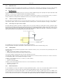
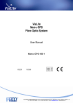
ViaLite HD Fibre Optic Link System User Manual HRK-HB-1 CR2724 08/03/2010 Pulse Power & Measurement Ltd, 65 Shrivenham Hundred Business Park, Watchfield, Swindon, Wiltshire SN68TY, UK Tel +44 (0)1793 784389 Fax +44 (0)1793 784391 Email [email protected] Web www.vialite.com PPM LTD 2010 2 PPM LTD 2010 Instrument Care and Safety Information Please read the whole of this section before using your ViaLiteHD product. It contains important safety information and will enable you to get the most from your Fibre Optic link. Electrical Safety The ViaLiteHD rack case provides the termination for power inputs and can be fitted with power supplies. The ViaLiteHD rack case is a Safety Class 1 product (having metal case directly connected to earth via the power supply cable). When operating the equipment note the following precautions: • • • • • Hazardous voltages exist within the equipment. There are no user serviceable parts inside; the covers should only be removed by a qualified technician. There are no user replaceable fuses in the rack case mounted equipment. Replacement should only be carried out by a PPM technician. The rack case earth stud SHOULD be connected to the safety earth. When using a 2 pin power supply cable the rack case earth stud MUST be connected to the safety earth. The ViaLiteHD Power Supply Modules do not have an isolating switch on the mains voltage inlet. For this reason, the ViaLiteHD Rack Case must be installed within easy reach of a clearly labelled dual pole mains isolation switch, which supplies the equipment. ESD Precautions The ViaLiteHD rack case is not equipped with any active electronics but it may be fitted with them. Precautions for handling electro-static sensitive devices should be observed when handling all ViaLiteHD modules. Technicians should ensure that they use effective personal grounding (i.e. ESD wrist strap etc.) when servicing the equipment. Any equipment or tools used should be grounded to prevent static charge build-up. Good practice should be observed at all times. For reference see relevant standards. EN 61340-5-1, “Protection of Electronic Devices from Electrostatic Phenomena – General Requirements” Optical Safety The ViaLiteHD rack case is not equipped with optical units but it may be fitted with them The ViaLiteHD RF Transmitter and Transceiver modules contain laser diode sources operating at nominal wavelengths of 1270nm to 1610nm. These devices are rated as EN60825-1:1994 CLASS 1 radiation emitting devices. A class 1 laser is safe under all conditions of normal use. When operating the equipment note the following precautions: • • • Never look into the end of an optical fibre directly or by reflection either with the naked eye or through an optical instrument. Never leave equipment with radiating bare fibres – always cap the connectors. Do not remove equipment external covers when operating. 3 PPM LTD 2010 TABLE OF CONTENTS 1 INITIAL INSPECTION............................................................................................................................................................................. 5 2 INTRODUCTION TO THE VIALITEHD RANGE ..................................................................................................................................... 5 3 VIALITEHD AND VIALITE CLASSIC COMPATIBILITY .......................................................................................................................... 5 4 VIALITEHD SYSTEM COMPONENTS ................................................................................................................................................... 6 4.1 ViaLiteHD 19” Rack Case................................................................................................................................................................... 6 4.2 Description ......................................................................................................................................................................................... 6 4.3 Power Interface Management............................................................................................................................................................. 6 4.4 Alarm Management ............................................................................................................................................................................ 7 4.5 Heat management.............................................................................................................................................................................. 8 4.6 Unused module positions ................................................................................................................................................................... 8 4.7 Minimum power supply load ............................................................................................................................................................... 8 4.8 Rack case Specification ..................................................................................................................................................................... 8 4.9 Rack connector pinouts...................................................................................................................................................................... 9 4.10 Fan replacement .............................................................................................................................................................................. 10 5 VIALITEHD POWER SUPPLIES .......................................................................................................................................................... 11 5.1 6HP Rack Case Power Supplies ...................................................................................................................................................... 11 5.2 19” Rack Case Power Requirements................................................................................................................................................ 12 5.3 Specification..................................................................................................................................................................................... 12 6 INSTALLATION GUIDE........................................................................................................................................................................ 13 6.1 Rack case Installation ...................................................................................................................................................................... 13 6.2 6HP Power Supply Module Installation (slots 15 and 16).................................................................................................................. 13 6.3 5HP Blindmate Plug-in Modules (slots 1-13) .................................................................................................................................... 13 6.4 5HP Standard Plug-in Modules (slots 1-13)...................................................................................................................................... 14 6.5 7HP Standard Plug-in Modules (slot 14 only) ................................................................................................................................... 15 7 MAINTENANCE AND FAULT-FINDING GUIDE ................................................................................................................................... 16 8 PRODUCT WARRANTY ...................................................................................................................................................................... 17 4 PPM LTD 2010 1 Initial Inspection Unpack and inspect the equipment as soon as possible. If there is any sign of damage or any parts missing, do not install the equipment before seeking advice from PPM or your local agent. The equipment received should match the delivery note that is shipped with the equipment. If there are any discrepancies, contact PPM or your local agent. 2 Introduction to the ViaLiteHD Range The ViaLiteHD range has been developed to provide a modular solution to the transmission of a wide range of analogue and digital data where traditional ‘copper wire’ systems cannot be used, for example, in electrically noisy environments or over long distances. The range is ideal for permanent and semi-permanent installation in Satellite communications, GPS, antenna remoting and other related applications. The variety of links available includes low frequency timing (2kHz) to wideband RF (4.2GHz), RF splitters, Oscillators, Amplifiers and Protection switches; they also include a full suite of supporting functions including RS232/422/485, Ethernet (to 1000 BT) and control systems to monitor and control the system with both Web and SNMP interfaces. All ViaLiteHD equipment operates over high quality glass fibre optic cable, which can be supplied in low-cost 3mm jacket, riser and outdoor specifications. The links can also be used with existing cable systems at customer premises. A ViaLiteHD system can be added to at any time, enabling the system to evolve with the needs of the user. 3 ViaLiteHD and ViaLite Classic compatibility The RF and optical interfaces of most ViaLiteHD and ViaLite Classic modules are compatible. However the physical size, mounting systems and control of the units are different, so it will not be possible to fit ViaLiteHD module in a ViaLite Classic rack case or housing and vice versa. However it is possible for units of different types to interwork and be used to expand existing systems. Listed below is a brief summary of inter family compatibility. • • • • • • • • • • • RF RF + digital RS232 RS422 RS485 Ethernet Protection Switch RF Splitters Amplifier Oscillator SNMP Compatible optical and RF interfaces Compatible optical and RF interfaces Compatible optical and digital interfaces Compatible optical and digital interfaces Compatible optical and digital interfaces Units of matching speed have compatible optical and digital interfaces Compatible RF interfaces may need interface cable (no optical interface) Compatible RF interfaces (no optical interface) Compatible RF interfaces (no optical interface) Compatible RF interfaces (no optical interface) Not compatible Contact PPM or your local agent for more details. 5 PPM LTD 2010 4 ViaLiteHD System Components 4.1 ViaLiteHD 19” Rack Case 4.2 Description The 19” rack case is suitable for 19” rack mounting. There are two versions, one for alternating current (AC) power and one for direct current (DC) power. The rack cases accommodate up to thirteen (5HP) plug-in RF/data modules, one (7HP) control module and two (6HP) plug-in power supplies. The hot-swappable, dual power supply capability provides full redundancy and maximum reliability to avoid traffic loss in the event of a power supply failure. The rack cases incorporate a backplane PCB for the distribution of DC power, status alarms and data. Note: Each power supply position requires a separate power source to provide fully redundant protection. The plug-in modules simply plug into the rack case, allowing the user to replace modules quickly and easily or to upgrade the system with additional modules at any time. For ease of upgrade and replacement, most modules are offered with the option of a Blindmate interface, where all interface cables are captive in the rack hardware and not the module. Each of the RF/data module positions has a dedicated D type connector that provides access to all the digital data for that module; this is fitted to the rack backplane. All of the module alarm outputs, both digital alarms and analogue monitors, are routed to a SCSI-3 connector on the rear panel of the rack case. This connector also has the interface for the summary alarm relay if a module has been fitted to provide this function. This permits the integration of the ViaLiteHD equipment into a Maintenance & Control system. All of the module external power connections (LNA feeds) and rack case backplane external power connections are routed to a second SCSI-3 connector on the rear panel of the rack case. Module slots 1-14 have a data bus that can be used for sending and receiving data between modules. 4.3 Power Interface Management External power can be provided to, or taken from the rack via the “Power Concentrator” connector J4, the current should be limited to 1A per pin for single pins or 0.8A per pin for shared pins. The power level must be within the capability of the rack case power supplies, see specification in section 5. 4.3.1 External backplane power If the rack case is powered externally with no PSUs fitted, the DC voltage measured at J4 should be 12Vdc +/- 0.5V. It is also possible to provide external power to rack cases fitted with PSUs, for this reason the current share bus (CSB) is available on “Power Concentrator” connector J4. If this option is used the rack case must be interfaced to PPM approved external power supplies, and the +12Vdc, GND and CSB lines for each power source should be connected in parallel. 6 PPM LTD 2010 4.3.2 Module bias feed It is possible to provide a bias voltage from the modules to connected devices. Dependent on module type, this can be either internally sourced from the module or provided via the “Power Concentrator” connector J4. The current limit is dependent on module type fitted. 4.4 Alarm Management The alarm strategy on the ViaLiteHD system caters for all levels of Alarm and Monitoring System complexity from simple module failure LED indication, to local and remote end alarm notification and redundancy switching. All modules provide an alarm output to the rack case backplane to indicate that the module is present and working correctly. The alarm is fail-safe in that when a working module is withdrawn from the rack case an alarm is registered for that module position. 4.4.1 “Alarm Concentrator” 50way Connector J1 All module alarms are provided for the user on the 50 way “Alarm Concentrator” connector on the rack case rear panel. These outputs are "open collector" outputs. There are also two analogue monitors per module position. Their function depends on the type of module fitted. 4.4.2 Connecting to an "open collector" output. The alarm output pin should be connected to a suitable current source (a positive voltage via a 10kohm pull-up resistor is adequate). When the module is in a working (non-alarm) state, the alarm output pin is short circuited to ground by the module. If the module enters an alarm state, the alarm pin is released to a high impedance state and current is no longer drawn from the constant current source. In the case of a positive voltage and pull-up resistor, the voltage on the alarm output pin will rise to indicate the alarm state. It follows that, if a module is removed from the rack case, the alarm will be raised for that module position. Internal to module External to module Vext Pull up Resistor Alarm Ground The capability of the open collector is dependent on the module that provides it. The typical capability of the Open Collector/Drain is 50mA maximum current sink and 15V maximum voltage (Vext) 4.4.3 Summary Alarm A summary alarm can be provided if an appropriate module is fitted in the 7HP slot (slot 14). This function can be provided by either of the following modules • SNMP control module (automatic sensing of module presence) • Summary alarm relay module (manual setting of module presence) If no module is fitted the summary alarm relay connections will all be open circuit. If an appropriate module is fitted there is a volt free 3-pin connection present on “Power Concentrator” Connector J4. The three connections are Normally Open (NO), Common (COM) and Normally Closed (NC). Condition 1 - Power applied to Rack Case, no alarms (i.e. normal condition) • Pin NO is open circuit • Pin NC is connected to COM Condition 2 - Power removed from Rack Case and/or one or more module alarms (i.e. Alarm condition) • Pin NO is connected to COM • Pin NC is open circuit 4.4.4 Module Alarm Defeat In some installations, the Rack Case might not be fully populated with modules. In this case, the module alarm output for the vacant positions would register a continuous alarm state and the Summary Alarm Output would also register an alarm condition. It is very important to ensure that the DIP switches on the Summary alarm relay module or software alarm mask of the SNMP control module for Rack Case positions where modules are “present” is set correctly. If a DIP switches/software mask is set incorrect for a “present” module, then if this module were to fail, NEITHER THE MODULE ALARM NOR THE SUMMARY ALARM WOULD DETECT THE 7 PPM LTD 2010 FAILURE. The front panel LEDs of the module will always register an alarm condition correctly regardless of the state of the DIP switches/software mask. 4.5 Heat management The rack is designed to meet it environmental specification, when operating in a typical configuration. A typical configuration is all modules populated (13*Transceiver, 1*SNMP, 2*PSU), rack power consumption 67 watts, no external DC power input or DC output and no obstruction to convection air path. Under normal operating conditions module slots 1-14 are cooled by convection, module slots 15 and 16 are force air cooled with exhaust at rear of the rack. The rack will continue to run without the forced cooling provided by the integrated fan but its operating temperature will be reduced. • Single PSU only fitted: maximum operating temperature reduced by -5°C • Airflow above blocked: maximum operating temperature reduced by -10°C • Airflow below blocked: maximum operating temperature reduced by -5°C • No forced air: maximum operating temperature reduced by -15°C 4.6 Unused module positions It is advised that all unused slots be fitted with blanking panels. Different widths of blanking panel are available these fit the 5HP general purpose (slots 1-13), 7HP controller card slots (slot 14), 6HP power supply (slots 15,16). They can be used with any ViaLiteHD 19inch rack case and will prevent accidental/unwanted access and the ingress of dust. 4.7 Minimum power supply load If the rack case power supplies are operating in dual redundant configuration, there should be a minimum load of 20 watts to ensure that both power supplies are active, below this level one power supply may be in idle mode (its LED will not be illuminated). If necessary a dummy load board can be supplied, to fit into any unused slots to meet this minimum power requirement. 4.8 Rack case Specification Description Max. No. of 5HP modules Max. No. of 7HP modules Max. No. of 6HP modules 19” Rack Mounting Desktop Mounting Width, internally Width, externally Height, internally Height, externally Depth, externally Weight (excl. modules) Cooling Operating Temperature Power Supply compatibility Rack power input Chassis earth Fan power Data Connector Alarm Concentrator Connector J1: SCSI-3 Power Concentrator Connector J4: SCSI-3 ViaLiteHD plug-in module compatibility HRK2 HRK2-DC 19” Rack Mounting Case 13 (in slots 1-13 only) 1 (in slots 14 only) 2 (in slots 15,16 only) Yes Not Suitable (use ViaLite Classic products) 84 HP 483 mm 3U 134 mm 265 mm 1.6 kg Convection (slots 1-14); Forced air (slots 15,16) exhaust at rear -10°C to +50°C HPS HPS-DC 2 x IEC 60320, 3 pins each 2 x screw terminal, 2 pins each Rear panel M4 stud IDC male, Dual row 6 pin • DC power to rear mounted fan cassette 9way Female D with screw-lock termination at the rear of each module position (1 per 5 HP slot). • Data input/output for individual modules. This concentrates the alarms from each module to a common point. • Open Drain alarm (1 per 5 & 7HP slot) • Power Good (2 per 6 HP slot) • Analogue Monitor (2 per 5 HP slot) • Ground Type: 50 way connector Har-mik® female [SCSI-3] This concentrates the power connections and summary alarms to a common point. • +12Vdc backplane power • Ground • Current sharing bus • Summary Alarm relay (optional) • External LNA bias (1 per 5 HP slot) Type: 50 way connector Har-mik® female [SCSI-3] All types 8 PPM LTD 2010 4.9 Rack connector pinouts Pin out – J1 “Alarm Concentrator” connector* Pin Rack J1* Pin Rack J1* 1 GND 14 Analogue_monitor_B_8 2 ALARM_2 15 Analogue_monitor_B_1 0 3 ALARM_4 16 Analogue_monitor_B_1 2 4 ALARM_6 17 GND 5 ALARM_8 18 GND 6 ALARM_10 19 Analogue_monitor_A_1 7 ALARM_12 20 Analogue_monitor_A_3 8 ALARM_14 21 Analogue_monitor_A_5 9 ALARM_P_2 22 Analogue_monitor_A_7 10 GND 23 Analogue_monitor_A_9 11 Analogue_monitor_B_ 24 Analogue_monitor_A_1 2 1 12 Analogue_monitor_B_ 25 Analogue_monitor_A_1 4 3 13 Analogue_monitor_B_ 26 ALARM_1 6 Pin out – J4 “Power Concentrator” connector* Pin Rack J4* Pin Rack J4* 1 CSB 14 GND 2 Relay_terminal_2 15 LNA_feed_2 3 GND 16 LNA_feed_4 4 GND 17 LNA_feed_6 5 GND 18 LNA_feed_8 6 +12Vdc 19 LNA_feed_10 7 +12Vdc 20 LNA_feed_12 8 +12Vdc 21 GND 9 +12Vdc 22 GND 10 +12Vdc 23 GND 11 +12Vdc 24 GND 12 +12Vdc 25 GND 13 +12Vdc 26 Relay_terminal_3 Note: The Chassis and power ground are common Pin 27 28 29 30 31 32 33 34 35 36 37 38 39 Rack J1* ALARM_3 ALARM_5 ALARM_7 ALARM_9 ALARM_11 ALARM_13 GND ALARM_P_1 Analogue_monitor_B_1 Analogue_monitor_B_3 Analogue_monitor_B_5 Analogue_monitor_B_7 Analogue_monitor_B_9 Pin 40 41 42 43 44 45 46 47 48 49 50 Pin 27 28 29 30 31 32 33 34 35 36 37 38 39 Rack J4* Relay_terminal_1 GND GND GND +12Vdc +12Vdc +12Vdc +12Vdc +12Vdc +12Vdc +12Vdc LNA_feed_1 GND Pin 40 41 42 43 44 45 46 47 48 49 50 Rack J1* Analogue_monitor_B_11 Analogue_monitor_B_13 GND GND Analogue_monitor_A_2 Analogue_monitor_A_4 Analogue_monitor_A_6 Analogue_monitor_A_8 Analogue_monitor_A_10 Analogue_monitor_A_12 GND Rack J4* LNA_feed_3 LNA_feed_5 LNA_feed_7 LNA_feed_9 LNA_feed_11 LNA_feed_13 GND GND GND GND GND Pin Out – J19 to J31 “Module Data” connectors Pin Module Pin Rack Summary Pin Rack Summary 1 GND 4 7 TX_232_IN RX_422_OUT2 5 GND 8 TX_422_IN+ RX_232_OUT 3 6 9 TX_422_INRX_422_OUT+ RST_485 Note: Data on the connector is only for the module fitted in that 5HP slot and is printed beneath (J19 = slot 1, J20 = slot 2 … J31 = Slot 13) Connections in Blue are optional and only available on some types of module Pin Out – J32 “Fan power” connector Pin Module 1 +12Vdc 2 +12Vdc Pin 3 4 Rack Summary +12Vdc GND Pin 5 6 Rack Summary GND GND No.1 contact Contact No 1 Contact No 1 Contact No 2 6 Contact No 25 1 Note: Colour indicates relevant connector drawing * An optional mating half cable is available for use in ViaLiteHD system No.6 contact No.9 contact Contact No 50 5 9 No.5 contact Contact No 26 Contact No 6 Contact No 6 Rack connector: 50 way SCSI-3 Har-mik® female Fan connector: 6 way IDC dual row male All connectors are viewed looking into connector from mating interface Each connector is shown in the correct orientation for normally mounted 3U rack case 9 2 x 4-40 UNC thread Module connector: 9 way D-Type connector female PPM LTD 2010 4.10 Fan replacement If the fan is not turning, the fan cartridge assembly should be replaced. This can be completed without disconnecting the unit from the mains supply. Withdraw Fan Cassette Insert Fan Cassette Remove screws Tighten screws Insert Fan power connector Remove Fan power connector Please ensure that when the fan is outside of its safety enclosure it is disconnected from its power connector The fan is removed by the following procedure. • Disconnect the fan power connector J32. • Using a magnetic screw driver remove the two screws fixing the fan cassette • Withdraw the fan cassette The fan is replaced by the following procedure. • Insert the fan cassette • Using a magnetic screw driver fix the cassette in place using the two screws provided • Connect the fan power connector J32. • Check that air is being exhausted 10 PPM LTD 2010 5 5.1 ViaLiteHD Power Supplies 6HP Rack Case Power Supplies The HPS series power supplies provide DC power to all plug-in modules in the 19” rack case. Two versions are offered, HPS with universal mains input and HPS-DC with wide range DC input. Either one or two HPS modules can be fitted. Two HPS modules will provide dual redundant operation. Separate supply inputs mean that they can be operated from different supplies for even higher levels of availability. During normal operation, the supplies current share to maximise reliability. In the event of a failure all the rack current will be provided by the remaining operational module. The front panel LED provides a visual indication of failure, and a power good alarm output is available for use at the “Alarm Concentrator” connector. The units are fan-cooled for maximum reliability and each PSU offers an MTBF of 270,000 hours at an ambient temperature of 40°C. The HPS power supply has a wide range alternating current (AC) input and can operate from 110V and 230V nominal mains supplies. Mains power is applied at the rear of the units via an earthed IEC60320 connector, and regulated direct current (DC) power is supplied to the Rack Backplane PCB for distribution to the plug-in modules through a rear-mounted connectors. This connector is also used for reporting PSU alarm status. For DC versions HPS-DC, power is applied at the rear of the units via a 2-pole screw terminal connector; it will operate from a wide range DC input 20-72Vdc. Both types of power supply are internally fused; this fuse is only expected to fail under fault conditions. The fuse is located internally underneath the earthed safety cover; this is not user serviceable and must be returned to PPM for replacement. On the front panel the module has a single LED indicator. This reports the status of the module. IF the LED is GREEN the unit is operating in its normal non-alarm state. If the LED is OFF, the power supply is not supplying 12V and has either failed or is in standby mode, see section 4.7. 11 PPM LTD 2010 5.2 19” Rack Case Power Requirements The exact power requirements of modules are given in the module handbooks, however the details below maybe used to approximate the power output requirements from the rack mounted PSUs. The input power requirements can be calculated by using the power supply efficiency given in section 5.3 Single Transmitter Single Receiver Dual Transmitter Dual Receiver Transceiver SNMP controller Dummy load LNA feed AC to DC efficiency DC to DC efficiency 5.3 2.0 W Typical per slot 1.3 W Typical per slot 4.0 W Typical per slot 2.6 W Typical per slot 3.3 W Typical per slot 5.0 W Typical per slot 12.0 W Typical per slot up to an additional 11 watts per slot, if used see section 5.3 see section 5.3 Specification Description Dimensions, internal (W x H) Dimensions, external (W x H x D) Weight Input Supply Power Fuse Efficiency Switch on current Output Voltage Output Ripple Maximum Output Power Minimum Load Power Inlet air Temperature Derating >+50°C Hot-swapping and Dual Redundant Output overload Output over voltage protection Status Indicators Rear Panel alarm outputs MTBF @40°C HPS HPS-DC Wide input range AC power supply Wide input range DC power supply 6HP * 3U 188 x 129 x 30 mm 1.5kg 110V or 230V nominal at 50/60Hz 20 – 72Vdc 88 - 264V absolute range Internally fused 4 A / 250 Vac Internally fused 10 A / 125 V 75% 84% <20A @ 230Vac <6.5A @ 20V input 12.0 +/ -0.5Vdc 50mV 100 W single PSU 180 W dual redundant PSUs 0 W single PSU 20 W dual redundant PSUs -10 to +50°C 1.5% / °C, absolute maximum 70°C 3% / °C, absolute maximum 70°C Yes Built in overload protection switches output OFF and automatically restarts at 110% nominal current 19Vdc Front panel GREEN power LED Power Good on J1 “Alarm Concentrator” connector 12V = Normal operation; 0V = Alarm 270 000 hours at 100% load 12 PPM LTD 2010 6 Installation Guide 6.1 Rack case Installation The ViaLiteHD Power Supply Modules do not have an isolating switch on the mains voltage inlet. For this reason, the ViaLiteHD Rack Case must be installed within easy reach of a clearly labelled dual pole mains isolation switch, which supplies the equipment. The ViaLiteHD 19” Rack Case is designed to fit 19” cabinets and occupies a height of 3U. The Rack Case is provided with flanges for mounting to the rack. The Rack Case backplane contains 9-way D-type data connectors for each module position. This provides user access to data connections from relevant modules (depends on module type). The pinouts of these connectors depend on the type of module in use in that rack position. There is also an “Alarm concentration” connector providing access to alarms and monitoring information from all modules and a “Power Concentration” connector that provides access to various power feeds and the summary alarm. 6.2 6HP Power Supply Module Installation (slots 15 and 16) The ViaLiteHD Power Supply Module powers the plug-in modules via the Rack Case backplane PCB. It occupies slots 15 and 16. To install a 6HP power supply module • Push the release button of the module handle down and simultaneously pull the top of the handle forwards. • Align the module upright and perpendicular to the front face of the rack so that the PCB slides into the “straight” card guides top and bottom. • Gently push the module down its guide, applying pressure via the handle; you may also apply pressure just above the LED. Avoid applying pressure on the ventilation grill. • As the module is fully mated the top of the handle should snap back and lock in position. • The pawls of the handle should be fully engaged in the matching slots. To remove a 6HP power supply module • Push the release button of the module handle down and simultaneously pull the top of the handle forwards. • Apply pressure via the handle and gently withdraw the module from the rack. 6.3 5HP Blindmate Plug-in Modules (slots 1-13) All ViaLiteHD plug-in modules are hot-swappable, so it is not necessary to power-down the Rack Case before inserting a module. All blind mate optical connectors are provided with spring loaded covers that will protect the optics of any inserted modules. As there is no cover on the opposite side, mating cables should not be installed until the slot modules are present. To install a blind mate module and matching interface plate • Firstly inspect the rear Blindmating plate, ensure that the connector barrels are fitted into all RF connectors and are centrally aligned. • Remove protective covers from the inside face of the optical connector if fitted • Ensure that the rear plate is free of any dust and contamination, if necessary clean with filtered compressed air. • Screw the Blindmating plate into the appropriate slot at the rear of the rack, using the supplied screws and a “Pozidriv Number 1” screwdriver • Push the release button of the module handle down and simultaneously pull the top of the handle forwards. • Remove the protective cover from the modules optical connectors and clean any optical connectors • Align the module upright and perpendicular to the front face of the rack so that the PCB slides into the “crow’s feet” card guides top and bottom. • Gently push the module down its guide, applying pressure via the handle, you may also apply pressure between the LED and test connector. • As the module is fully mated the top of the handle should snap back and lock in position. • The pawls of the handle should be fully engaged in the matching slots. • If power is applied to the rack the module power LED should light as soon as the module is fully inserted • Connect any interface cables to the blind mate plate 13 PPM LTD 2010 To remove a blind mate module • Push the release button of the module handle down and simultaneously pull the top of the handle forwards. • Apply pressure via the handle and gently withdraw the module from the rack. • Check that the RF mating barrel is retained by the rack Blindmating plate • All cables with be retained by the rack case. Note if modules are absent for an extended period there is chance of the optical fibres being contaminated as the optical mating interface is unprotected. If this happens it will be necessary to clean both the blind mating adaptor and fibre optic cable. 6.4 5HP Standard Plug-in Modules (slots 1-13) All ViaLiteHD plug-in modules are hot-swappable, so it is not necessary to power-down the rack before inserting a module. All standard optical connectors are retained by the module. So it will be necessary to either disconnect any cables or have a sufficiently long service loop. To install a 5HP Standard module and matching interface plate • The protective covers on the connectors may be left in place. • Push the release button of the module handle down and simultaneously pull the top of the handle forwards. • Align the module upright and perpendicular to the front face of the rack so that the PCB slides into the “crow’s feet” card guides top and bottom. • Gently push the module down its guide, applying pressure via the handle, you may also apply pressure between the LED and test connector. • As the module is fully mated the top of the handle should snap back and lock in position. • The pawls of the handle should be fully engaged in the matching slots. • If power is applied to the rack the module power LED should light as soon as the module is fully inserted • Remove protective covers and connect any interface cables To remove a 5HP Standard module • Disconnect any cables if necessary • Push the release button of the module handle down and simultaneously pull the top of the handle forwards. • Apply pressure via the handle and gently withdraw the module from the rack. 14 PPM LTD 2010 6.5 7HP Standard Plug-in Modules (slot 14 only) All ViaLiteHD plug-in modules are hot-swappable, so it is not necessary to power-down the rack before inserting a module. All standard optical connectors are retained by the module. So it will be necessary to either disconnect any cables or have a sufficiently long service loop. To install a 7HP Standard module • The protective covers on the connectors may be left in place. • Push the release button of the module handle down and simultaneously pull the top of the handle forwards. • Align the module upright and perpendicular to the front face of the rack so that the PCB slides into the “crow’s feet” card guides top and bottom. • Gently push the module down its guide, applying pressure via the handle, you may also apply pressure between the LED and test connector. • As the module is fully mated the top of the handle should snap back and lock in position. • The pawls of the handle should be fully engaged in the matching slots. • If power is applied to the rack the module power LED should light as soon as the module is fully inserted • Remove protective covers and connect any interface cables To remove a 7HP Standard module • Disconnect any cables if necessary • Push the release button of the module handle down and simultaneously pull the top of the handle forwards. • Apply pressure via the handle and gently withdraw the module from the rack. 15 PPM LTD 2010 7 Maintenance and Fault-Finding Guide Refer to the following table that gives a list of commonly encountered problems and suggested solutions. Fault Possible Causes Solution Power LED does not illuminate on the plug-in PSUs. Power is not connected to the PSU. Connect mains power to the rear of the PSU. Check fuses of power leads. PSU is in idle mode. Add additional dummy load board or plug in modules. Power LED does not light. Fuse has blown in PSU. Power supply is not connected. Return the unit to PPM or your local agent. Attach power source. Fan not turning. Fan power disconnected. Check fan power connector is inserted. Difficulty inserting module. Incorrect alignment. Check that the module is correctly fitted in the card guides. Incorrect module slot. Check that module is in correct slot Slots 1-13 for 5HP modules Slot 14 for 7 HP modules Slot 15-16 for 6 HP modules Check that the DIP switches on the Summary alarm relay module for all rack case positions are set correctly. Summary alarm triggered when no module failure is indicated. Open collector alarms for unused slots not masked. Check the software alarm mask of the SNMP control module for all rack case positions is set correctly. Failed Module. Return the unit to PPM or your local agent. In the event of any problems or queries about the equipment, contact PPM or your local agent. For module fault finding information see module handbooks 16 PPM LTD 2010 8 Product Warranty The Company guarantees its products, and will maintain them for a period of three years from the date of shipment and at no cost to the customer. Extended warranty options are available at the time of purchase. Please note that the customer is responsible for shipping costs to return the unit to PPM. The Company or its agents will maintain its products in full working order and make all necessary adjustments and parts replacements during the Company’s normal working hours provided that the Customer will pay at the rates currently charged by the Company for any replacements made necessary by accident, misuse, neglect, wilful act or default or any cause other than normal use. Claims must be made promptly, and during the warranty period. IMPORTANT:Please contact both your selling agent and PPM prior to returning any goods for Warranty or Non-Warranty repairs. Goods will not be accepted without a valid Goods Return Number (GRN). ViaLiteHD USER MANUAL (HRK-HB) ISSUE 1 CR2724 PULSE POWER & MEASUREMENT LTD 2010 NO PART OF THIS DOCUMENT MAY BE REPRODUCED OR TRANSMITTED IN ANY FORM WITHOUT PRIOR WRITTEN PERMISSION. PPM, 65 SHRIVENHAM HUNDRED BUSINESS PARK, SWINDON, SN6 8TY, UK. TEL: +44 1793 784389 FAX: +44 1793 784391 EMAIL : [email protected] W EBSITE : WWW .VIALITE.COM