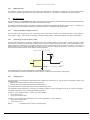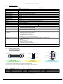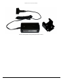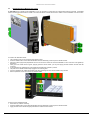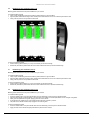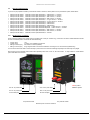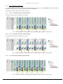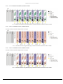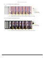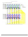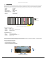
1
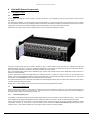
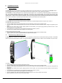
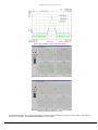
ViaLite HD Fibre Optic Link System 3U chassis User Manual HRK3-HB-5 CR3274 17/12/14 Pulse Power & Measurement Ltd, 65 Shrivenham Hundred Business Park, Watchfield, Swindon, Wiltshire SN68TY, UK Tel +44 (0)1793 784389 Fax +44 (0)1793 784391 Email [email protected] Web www.vialite.com HRK3-HB-5 VIALITEHD 3U CHASSIS HANDBOOK Instrument Care and Safety Information Please read the whole of this section before using your ViaLiteHD product. It contains important safety information and will enable you to get the most from your Fibre Optic link. Electrical Safety The ViaLiteHD chassis provides the termination for power inputs and can be fitted with power supplies. The ViaLiteHD chassis is a Safety Class 1 product (having metal chassis directly connected to earth via the power supply cable). When operating the equipment note the following precautions: Hazardous voltages exist within the equipment. There are no user serviceable parts inside; the covers MUST NOT be removed. There are no user replaceable fuses in the chassis mounted equipment. Replacement should only be carried out by a ViaLite Communications technician. The chassis earth stud SHOULD be connected to the safety earth. When using a 2 pin power supply cable the chassis earth stud MUST be connected to the safety earth. The ViaLiteHD Power Supply Modules do not have an isolating switch on the mains voltage inlet. For this reason, the ViaLiteHD chassis MUST be installed within easy reach of a clearly labelled dual pole mains isolation switch, which supplies the equipment. PSU modules are fused on the mains live feed only. A second fuse should be used for the neutral connection where the polarity of the connectors can be reversed; rating should match those given in section 5.1.1. ESD Precautions The ViaLiteHD chassis is not equipped with any active electronics but it may be fitted with them. Precautions for handling electro-static sensitive devices should be observed when handling all ViaLiteHD modules. Technicians should ensure that they use effective personal grounding (i.e. ESD wrist strap etc.) when servicing the equipment. Any equipment or tools used should be grounded to prevent static charge build-up. Good practice should be observed at all times. For reference see relevant standards. EN 61340-5-1, “Protection of Electronic Devices from Electrostatic Phenomena – General Requirements” Optical Safety The ViaLiteHD chassis is not equipped with optical units but it may be fitted with them The ViaLiteHD RF Transmitter and Transceiver modules contain laser diode sources operating at nominal wavelengths of 1270nm to 1610nm. These devices are rated as EN60825-1:2007 CLASS 1 radiation emitting devices. A class 1 laser is safe under all conditions of normal use. When operating the equipment note the following precautions: Never look into the end of an optical fibre directly or by reflection either with the naked eye or through an optical instrument. Never leave equipment with radiating bare fibres – always cap the connectors. Do not remove equipment external covers when operating. Hot surface The ViaLiteHD Redundancy load module may have hot surfaces when operating under fulll load. The hot surfaces are not accessible when fitted in an approved chassis installation. Suitable precaution should be taken when handling this device. Allow to cool for 10 minutes Do not touch metallic surfaces or printed circuit board when hot. When handling, hold front panel and handle only. 2 HRK3-HB-5 VIALITEHD 3U CHASSIS HANDBOOK TABLE OF CONTENTS 1 INITIAL INSPECTION ............................................................................................................................................................................ 5 2 INTRODUCTION TO THE VIALITEHD RANGE ..................................................................................................................................... 5 3 VIALITEHD AND VIALITE CLASSIC COMPATIBILITY .......................................................................................................................... 6 4 VIALITEHD SYSTEM COMPONENTS ................................................................................................................................................... 7 4.1 ViaLiteHD 19” chassis................................................................................................................................................................ 7 4.2 Description................................................................................................................................................................................. 7 4.3 Power Interface Management .................................................................................................................................................... 7 4.3.1 External backplane power ............................................................................................................................................. 7 4.3.2 Module bias feed ........................................................................................................................................................... 8 4.4 Alarm Management ................................................................................................................................................................... 8 4.4.1 “Alarm Concentrator” 50way Connector J1 .................................................................................................................... 8 4.4.2 Connecting to an "open collector" output. ...................................................................................................................... 8 4.4.3 Summary Alarm............................................................................................................................................................. 8 4.4.4 Module Alarm Defeat ..................................................................................................................................................... 9 4.4.5 Using open collector alarms with controller cards .......................................................................................................... 9 4.4.6 Using open collector alarms with RF switch and RF splitter cards ................................................................................. 9 4.5 Heat management ..................................................................................................................................................................... 9 4.6 Unused module positions ........................................................................................................................................................... 9 4.7 Minimum power supply load..................................................................................................................................................... 10 4.8 Chassis Specification ............................................................................................................................................................... 11 4.9 Chassis connector pinouts ....................................................................................................................................................... 11 4.9.1 Chassis connector pin out J4 & J19-31........................................................................................................................ 12 4.9.1.1 Chassis connector pin out J4 & J19-31 - serial numbers below and including SN1221901 .................................................. 12 4.9.1.2 Chassis connector pin out J4 & J19-31 - serial numbers above and including SN1221902 .................................................. 12 4.9.2 LNA feed and BUC feed pin assignment for different module types ............................................................................. 13 4.10 Fan replacement ...................................................................................................................................................................... 14 5 VIALITEHD POWER SUPPLIES .......................................................................................................................................................... 15 5.1 6HP Chassis Power Supplies .................................................................................................................................................. 15 5.1.1 Specification ................................................................................................................................................................ 16 5.2 19” Chassis Power Requirements ............................................................................................................................................ 16 5.3 Redundancy load module, HRL ............................................................................................................................................... 16 5.3.1 Redundancy load module, plug-in card........................................................................................................................ 17 5.3.2 Redundancy load module, front panel ......................................................................................................................... 17 5.3.3 Redundancy load module, DIP switches ...................................................................................................................... 17 5.3.4 Redundancy load module, setting the load DIP switches ............................................................................................. 18 5.3.5 Redundancy load module, using with SNMP and controller module............................................................................. 18 5.4 Power Supply HPS-CS-3 for use with OEM modules (HRx-xx-xM-xx)...................................................................................... 18 6 INSTALLATION GUIDE ....................................................................................................................................................................... 20 6.1 Chassis Installation .................................................................................................................................................................. 20 6.2 6HP Power Supply Module Installation (slots 15 and 16) ......................................................................................................... 20 6.3 5HP Standard Plug-in Modules (slots 1-13) ............................................................................................................................. 20 6.4 5HP Blindmate Plug-in Modules (slots 1-13) ............................................................................................................................ 21 6.5 7HP Standard Plug-in Modules (slot 14 only) ........................................................................................................................... 22 6.6 5HP blanking panel installation (slots 1-13).............................................................................................................................. 23 6.7 7HP blanking panel installation (slot 14) .................................................................................................................................. 23 6.8 6HP blanking panel installation (slots 15, 16) ........................................................................................................................... 23 6.9 Separate blindmate panels ...................................................................................................................................................... 24 6.10 Electrical power connection ..................................................................................................................................................... 24 6.11 Typical redundancy configurations ........................................................................................................................................... 25 6.11.1 Four 1:1 redundant transmitters, standard modules ..................................................................................................... 25 6.11.2 Four 1:1 redundant transmitters, blindmate modules ................................................................................................... 25 6.11.3 Six 1:1 redundant transmitters, standard modules ....................................................................................................... 25 6.11.4 Six 1:1 redundant transmitters, blindmate modules ..................................................................................................... 26 6.11.5 Four 1:1 redundant receivers, standard modules ......................................................................................................... 26 6.11.6 Four 1:1 redundant receivers, blindmate modules ....................................................................................................... 26 6.11.7 Six 1:1 redundant receivers, standard modules ........................................................................................................... 27 6.11.8 Six 1:1 redundant receivers, blindmate modules.......................................................................................................... 27 6.11.9 Four 1:1 redundant links, blindmate modules .............................................................................................................. 28 6.11.10 Six 1:1 redundant links, blindmate modules ................................................................................................................. 29 6.12 Shock and vibration ................................................................................................................................................................. 30 7 PART NUMBERING ............................................................................................................................................................................. 32 7.1 ViaLiteHD Chassis, part numbering ......................................................................................................................................... 32 7.2 ViaLiteHD Power supply, part numbering ................................................................................................................................. 32 8 MAINTENANCE AND FAULT-FINDING GUIDE ................................................................................................................................... 33 3 HRK3-HB-5 VIALITEHD 3U CHASSIS HANDBOOK 9 PRODUCT WARRANTY ...................................................................................................................................................................... 34 10 FCC APPROVAL ................................................................................................................................................................................. 34 4 HRK3-HB-5 VIALITEHD 3U CHASSIS HANDBOOK 1 Initial Inspection Unpack and inspect the equipment as soon as possible. If there is any sign of damage or any parts missing, do not install the equipment before seeking advice from ViaLite Communications or your local agent. The equipment received should match the delivery note that is shipped with the equipment. If there are any discrepancies, contact ViaLite Communications or your local agent. 2 Introduction to the ViaLiteHD Range The ViaLiteHD range has been developed to provide a modular solution to the transmission of a wide range of analogue and digital data where traditional ‘copper wire’ systems cannot be used, for example, in electrically noisy environments or over long distances. The range is ideal for permanent and semi-permanent installation in Satellite communications, GPS, antenna remoting and other related applications. The variety of links available includes low frequency timing (2kHz) to wideband RF (4.2GHz), RF splitters, amplifiers and switches; they also include a full suite of supporting functions including RS232/422/485, Ethernet and control systems to monitor and control the system with both Web and SNMP interfaces. All ViaLiteHD equipment operates over high quality glass fibre optic cable, which can be supplied in low-cost 3mm jacket, riser and outdoor specifications. The links can also be used with existing cable systems at customer premises. A ViaLiteHD system can be added to at any time, enabling the system to evolve with the needs of the user. ViaLiteHD is a product brand manufactured by Pulse Power and Measurement Ltd (PPM). ViaLite Communications is a division of Pulse Power and Measurement Ltd (PPM). 5 HRK3-HB-5 VIALITEHD 3U CHASSIS HANDBOOK 3 ViaLiteHD and ViaLite Classic compatibility The RF and optical interfaces of most ViaLiteHD and ViaLite Classic modules are compatible. However the physical size, mounting systems and control of the modules are different, so it will not be possible to fit ViaLiteHD module in a ViaLite Classic chassis or housing and vice versa. However it is possible for modules of different types to interwork and be used to expand existing systems. Listed below is a brief summary of inter family compatibility. RF RF + digital RS232 RS422 RS485 Ethernet Redundancy Switch RF Splitters Amplifier SNMP Compatible optical and RF interfaces Compatible optical and RF interfaces Compatible optical and digital interfaces Compatible optical and digital interfaces Compatible optical and digital interfaces Modules of matching speed have compatible optical and digital interfaces Compatible RF interfaces may need interface cable (no optical interface) Compatible RF interfaces (no optical interface) Compatible RF interfaces (no optical interface) Not compatible Contact ViaLite Communications or your local agent for more details. 6 HRK3-HB-5 VIALITEHD 3U CHASSIS HANDBOOK 4 ViaLiteHD System Components 4.1 ViaLiteHD 19” chassis 4.2 Description The 19” chassis is suitable for 19” rack mounting. There are two versions, one for alternating current (AC) power and one for direct current (DC) power. The chassis accommodates up to thirteen (5HP) plug-in RF/data modules, one (7HP) control module and two (6HP) plug-in power supplies. The hot-swappable, dual power supply capability provides full redundancy and maximum reliability to avoid traffic loss in the event of a power supply failure. The chassis incorporates a backplane PCB for the distribution of DC power, status alarms and data. Note: Each power supply position requires a separate power source to provide fully redundant protection. The plug-in modules simply plug into the chassis, allowing the user to replace modules quickly and easily or to upgrade the system with additional modules at any time. For ease of upgrade and replacement, most modules are offered with the option of a Blindmate interface, where all interface cables are connected to in the chassis hardware and not the module. Each of the RF/data module positions has a dedicated D type connector that provides access to all the digital data for that module; this is fitted to the chassis backplane. All of the module alarm outputs, both digital alarms and analogue monitors, are routed to a SCSI-3 connector on the rear panel of the chassis. This connector also has the interface for the summary alarm relay if a module has been fitted to provide this function. This permits the integration of the ViaLiteHD equipment into a Maintenance & Control system. All of the module external power connections (LNA feeds) and chassis backplane external power connections are routed to a second SCSI-3 connector on the rear panel of the chassis. Module slots 1-14 have a data bus that can be used for sending and receiving data between modules. 4.3 Power Interface Management External power can be provided to, or taken from the chassis via the “Power Concentrator” connector J4, the current should be limited to 1A per pin for single pins or 0.8A per pin for shared pins. The power level (sum of chassis and external power) must be within the capability of the chassis power supplies, see specification in section 5.2. 4.3.1 External backplane power If the chassis is powered externally the input DC voltage measured at the power concentrator connector should be 12Vdc +/- 0.5V. If chassis power supplies are also fitted we would advise that a low voltage drop diode (i.e. Schottky or similar) be used to OR the power feeds. It is also possible to provide external power to a chassis fitted with PSUs, for this reason the current share bus (CSB) is available on “Power Concentrator” connector J4. If this option is used the chassis must be interfaced to ViaLite Communications approved external power supplies, and the +12Vdc, GND and CSB lines for each power source should be connected in parallel. 7 HRK3-HB-5 VIALITEHD 3U CHASSIS HANDBOOK 4.3.2 Module bias feed It is possible to provide a bias voltage from the modules to connected devices. Dependent on module type, this can be either internally sourced from the module or provided via the “Power Concentrator” connector J4. The current limit is dependent on module type fitted. 4.4 Alarm Management The alarm strategy on the ViaLiteHD system caters for all levels of Alarm and Monitoring System complexity from simple module failure LED indication, to local and remote end alarm notification and redundancy switching. All modules provide an alarm output to the chassis backplane to indicate that the module is present and working correctly. The alarm is failsafe in that when a working module is withdrawn from the chassis an alarm is registered for that module position. 4.4.1 “Alarm Concentrator” 50way Connector J1 All module alarms are provided for the user on the 50 way “Alarm Concentrator” connector on the chassis rear panel. These outputs are "open collector" outputs. There are also two analogue monitors per module position. Their function depends on the type of module fitted. 4.4.2 Connecting to an "open collector" output. The alarm output pin should be connected to a suitable current source (a positive voltage via a 10kohm pull-up resistor is adequate). When the module is in a working (non-alarm) state, the alarm output pin is short circuited to ground by the module. If the module enters an alarm state, the alarm pin is released to a high impedance state and current is no longer drawn from the constant current source. In the case of a positive voltage and pull-up resistor, the voltage on the alarm output pin will rise to indicate the alarm state. It follows that, if a module is removed from the chassis, the alarm will be raised for that module position. Internal to module External to module Vext Pull up Resistor Alarm Ground The capability of the open collector is dependent on the module that provides it. The typical capability of the Open Collector/Drain is 50mA maximum current sink and 15V maximum voltage (Vext) 4.4.3 Summary Alarm A summary alarm can be provided if an appropriate module is fitted in the 7HP slot (slot 14). This function can be provided by either of the following modules SNMP control module (automatic sensing of module presence) Summary alarm relay module (manual setting of module presence) If no module is fitted the summary alarm relay connections will all be open circuit. If an appropriate module is fitted there is a volt free 3-pin connection present on “Power Concentrator” Connector J4. The three connections are Normally Open (NO), Common (COM) and Normally Closed (NC). Condition 1 - Power applied to chassis, no alarms (i.e. normal condition) Pin NO is open circuit Pin NC is connected to COM Condition 2 - Power removed from chassis and/or one or more module alarms (i.e. Alarm condition) Pin NO is connected to COM Pin NC is open circuit RELAY_x [1= normally closed, 2=common, 3=normally open] 8 HRK3-HB-5 VIALITEHD 3U CHASSIS HANDBOOK 4.4.4 Module Alarm Defeat In some installations, the chassis might not be fully populated with modules. In this case, the module alarm output for the vacant positions would register a continuous alarm state and the Summary Alarm Output would also register an alarm condition. It is very important to ensure that the DIP switches on the Summary alarm relay module or software alarm mask of the SNMP control module for chassis positions where modules are “present” is set correctly. If a DIP switches/software mask is set incorrectly for a “present” module, then if this module were to fail, NEITHER THE MODULE ALARM NOR THE SUMMARY ALARM WOULD DETECT THE FAILURE. The front panel LEDs of the module will always register an alarm condition correctly regardless of the state of the DIP switches/software mask. 4.4.5 Using open collector alarms with controller cards When a chassis is fitted with a controller card (i.e. SNMP and web controller or summary alarm card) all the alarm lines will be loaded and pulled up. The alarm lines are pulled up to as shown below. SNMP and web controller pulled up to 3.3V via 4.7k ohms* (see warning below) Summary Alarm pulled up to 5V via 100k ohm, with series diode * Applying external voltage to these pins may cause damage, contact ViaLite communications Note: the alarm line for slot 14 is always pulled up irrespective of the card status, these cards are all fitted with summary alarm relays. 4.4.6 Using open collector alarms with RF switch and RF splitter cards When a chassis is fitted with an RF switch or RF splitter card the alarm lines of the adjacent slots will be loaded and pulled up. The alarm lines are pulled up to as shown below. RF switch or RF splitter 4.5 pulled up to 5V via 10k ohm, with series diode Heat management The chassis is designed to meet its environmental specification, when operating in a typical configuration. A typical configuration is all modules populated (13*Transceiver, 1*SNMP, 2*PSU), chassis power consumption 67 watts, no external DC power input or DC output and no obstruction to convection air path. Under normal operating conditions module slots 1-14 are cooled by convection, module slots 15 and 16 are force air cooled with exhaust at rear of the chassis. The chassis will continue to run without the forced cooling provided by the integrated fan but its operating temperature will be reduced. Single PSU only fitted: Airflow above chassis blocked: Airflow below chassis blocked: No forced air: maximum operating temperature reduced by -5C maximum operating temperature reduced by -10C maximum operating temperature reduced by -5C maximum operating temperature reduced by -10C Also see section 5.2 that details the typical power consumption of most common types of modules. 4.6 Unused module positions We advised that all unused slots be fitted with blanking panels. Different widths of blanking panel are available these fit the 5HP general purpose (slots 1-13), 7HP controller card slots (slot 14), 6HP power supply slots (slots 15,16). They can be used with any ViaLiteHD 19inch chassis and will prevent accidental/unwanted access and the ingress of dust. Blanking panels available are. 85044 85050 HPS-0 85046 85049 ViaLiteHD Blank Panel, 5HP Reusable ViaLiteHD Blank Panel, 5HP ViaLiteHD Blank Panel, 6HP ViaLiteHD Blank Panel, 7HP Reusable ViaLiteHD Blank Panel, 7HP Slots 1-13 Slots 1-13 Slot 15, 16 Slot 14 Slot 14 Contact ViaLite Communications or your local agent for more details. There are two types of the 5 and 7 HP blanking panels. The standard blanking panels are fitted with snap in plastic barbs. These are designed to permanently hold the blanking panel in position. Please ensure that you have fully planned the configuration of your chassis, as the plastic barbs are a close tolerance fit and removal results in the barbs being broken; the panel should then be discarded. 9 HRK3-HB-5 VIALITEHD 3U CHASSIS HANDBOOK 85044 ViaLiteHD Blank Panel, 5HP 85046 ViaLiteHD Blank Panel, 7HP There are also reusable panels available (85049 and 85050) with handles to keep them in place. The 6 HP blanking panels are fitted with handles to secure them into either slot 15 or 16. These are design to permanently hold the blanking panel in position. HPS-0 ViaLiteHD Blank Panel, 6HP 4.7 Minimum power supply load If the chassis power supplies are operating in dual redundant configuration, there should be a minimum load of 12 watts to ensure that both power supplies are active, below this level one power supply may be in idle mode (its LED will not be illuminated). If necessary a redundancy load module can be supplied, to fit into any unused slots to meet this minimum power requirement, see section 5.3. 10 HRK3-HB-5 VIALITEHD 3U CHASSIS HANDBOOK Chassis Specification Description Max. No. of 5HP modules Max. No. of 7HP modules Max. No. of 6HP modules 19” Rack Mounting Desktop Mounting Width, internally Width, externally Height, internally Height, externally Depth, externally Maximum weight Cooling Operating Temperature Humidity Power Supply compatibility Chassis power input Chassis earth Fan power Data Connector Alarm Concentrator Connector J1: SCSI-3 Power Concentrator Connector J4: SCSI-3 ViaLiteHD plug-in module compatibility 4.9 HRK3 HRK3-DC 19” Rack Mounting Chassis 13 (in slots 1-13 only) 1 (in slots 14 only) 2 (in slots 15,16 only) Yes Not Suitable (use ViaLite Classic products) 84 HP 483 mm 3U 134 mm 265 mm 1.8 kg (chassis ONLY), 7.2 kg (chassis and slot modules) Convection (slots 1-14); Forced air (slots 15,16) exhaust at rear -10C to +50C 0-95%, Non-condensing HPS HPS-DC 2 x IEC 60320, 3 pins each 2 x screw terminal, 2 pins each Rear panel M4 stud IDC male, Dual row 6 pin DC power to rear mounted fan cassette 9way Female D with screw-lock termination at the rear of each module position (1 per 5 HP slot). Data input/output for individual modules. This concentrates the alarms from each module to a common point. Open Drain alarm (1 per 5 & 7HP slot) Power Good (2 per 6 HP slot) Analogue Monitor (2 per 5 HP slot) Ground Type: 50 way connector Har-mik® female [SCSI-3] This concentrates the power connections and summary alarms to a common point. +12Vdc backplane power Ground Current sharing bus Summary Alarm relay (optional) External LNA bias (1 per 5 HP slot) Type: 50 way connector Har-mik® female [SCSI-3] All types Chassis connector pinouts No.1 contact Contact No 1 Contact No 1 Contact No 2 6 Contact No 25 1 4.8 No.6 contact No.9 contact Contact No 50 5 9 No.5 contact Contact No 26 Chassis connector: 50 way SCSI-3 Har-mik® female 2 x 4-40 UNC thread Contact No 6 Contact No 6 Module connector: 9 way D-Type connector female Fan connector: 6 way IDC dual row male All connectors are viewed looking into connector from mating interface Each connector is shown in the correct orientation for normally mounted 3U chassis Pin Out – J32 “Fan power” connector Pin Chassis Fan Pin Chassis Fan 1 +12Vdc 3 +12Vdc 2 +12Vdc 4 GND Note: Colour indicates relevant connector drawing An optional mating half cable is available for use in ViaLiteHD system 11 Pin 5 6 Chassis Fan GND GND HRK3-HB-5 VIALITEHD 3U CHASSIS HANDBOOK Pin out – J1 “Alarm Concentrator” connector* Pin Chassis J1* Pin Chassis J1* Pin Chassis J1* 1 GND 14 Analogue_monitor_B_8 27 ALARM_3 2 ALARM_2 15 Analogue_monitor_B_10 28 ALARM_5 3 ALARM_4 16 Analogue_monitor_B_12 29 ALARM_7 4 ALARM_6 17 GND 30 ALARM_9 5 ALARM_8 18 GND 31 ALARM_11 6 ALARM_10 19 Analogue_monitor_A_1 32 ALARM_13 7 ALARM_12 20 Analogue_monitor_A_3 33 GND 8 ALARM_14 21 Analogue_monitor_A_5 34 ALARM_P_1 9 ALARM_P_2 22 Analogue_monitor_A_7 35 Analogue_monitor_B_1 10 GND 23 Analogue_monitor_A_9 36 Analogue_monitor_B_3 11 Analogue_monitor_B_2 24 Analogue_monitor_A_11 37 Analogue_monitor_B_5 12 Analogue_monitor_B_4 25 Analogue_monitor_A_13 38 Analogue_monitor_B_7 13 Analogue_monitor_B_6 26 ALARM_1 39 Analogue_monitor_B_9 Note: See your module handbooks for assignment and function of the “Analogue_monitor” pins 4.9.1 Pin 40 41 42 43 44 45 46 47 48 49 50 Chassis J1* Analogue_monitor_B_11 Analogue_monitor_B_13 GND GND Analogue_monitor_A_2 Analogue_monitor_A_4 Analogue_monitor_A_6 Analogue_monitor_A_8 Analogue_monitor_A_10 Analogue_monitor_A_12 GND Chassis connector pin out J4 & J19-31 The pin out of connectors J4 & J19-31 has been changed, to add additional functionality to the chassis. Check serial number to find correct pin out. See section 4.9.1.1 and 4.9.1.2 below. The approximate last shipment date of the early revision racks is July 2013, contact ViaLite Communications for more details. 4.9.1.1 Chassis connector pin out J4 & J19-31 - serial numbers below and including SN1221901 Below is the pin out of J4 and J19-J31 for all early production chassis with serial number below and including SN1221901. Pin Out – J19 to J31 “Module Data” connectors Pin Slot data Pin Slot data Pin Slot data 1 GND 4 TX_232_IN 7 RX_422_OUT2 TX_422_IN+ 5 GND 8 RX_232_OUT 3 TX_422_IN6 RX_422_OUT+ 9 RTS_485 Note: Data on the connector is only for the module fitted in that 5HP slot and is printed beneath (J19 = slot 1, J20 = slot 2 … J31 = Slot 13) Connections in Blue text are optional and only available on some types of module Pin out – J4 “Power Concentrator” connector* Pin Chassis J4* Pin Chassis J4* 1 CSB 14 GND 2 Relay_2 (COM) 15 LNA_feed_2 3 GND 16 LNA_feed_4 4 GND 17 LNA_feed_6 5 GND 18 LNA_feed_8 6 +12Vdc 19 LNA_feed_10 7 +12Vdc 20 LNA_feed_12 8 +12Vdc 21 GND 9 +12Vdc 22 GND 10 +12Vdc 23 GND 11 +12Vdc 24 GND 12 +12Vdc 25 GND 13 +12Vdc 26 Relay_3 (NO) Note: The Chassis and power ground are common 4.9.1.2 Pin 27 28 29 30 31 32 33 34 35 36 37 38 39 Chassis J4* Relay_1 (NC) GND GND GND +12Vdc +12Vdc +12Vdc +12Vdc +12Vdc +12Vdc +12Vdc LNA_feed_1 GND Pin 40 41 42 43 44 45 46 47 48 49 50 Chassis J4* LNA_feed_3 LNA_feed_5 LNA_feed_7 LNA_feed_9 LNA_feed_11 LNA_feed_13 GND GND GND GND GND Chassis connector pin out J4 & J19-31 - serial numbers above and including SN1221902 Below is the pin out of J4 and J19-J31 for all later production chassis with serial number above and including SN1221902. The backplane is marked ‘Issue C’ – this description can be found on the PCB between slot 13 and 14 when viewed from the front. Pin Out – J19 to J31 “Module Data” connectors Pin Chassis Summary Pin Chassis Summary Pin Chassis Summary 1 GND 4 TX_232_IN 7 RX_422_OUT2 TX_422_IN+ 5 RTS_485_2 8 RX_232_OUT 3 TX_422_IN6 RX_422_OUT+ 9 RTS_485_1 Note: Data on the connector is only for the module fitted in that 5HP slot and is printed beneath (J19 = slot 1, J20 = slot 2 … J31 = Slot 13) Connections in Blue are optional and only available on some types of module 12 HRK3-HB-5 VIALITEHD 3U CHASSIS HANDBOOK Pin out – J4 “Power Concentrator” connector* Pin Chassis J4* Pin Chassis J4* 1 CSB 14 GND 2 Relay_2 (COM) 15 LNA_feed_2 3 GND 16 LNA_feed_4 4 GND 17 LNA_feed_6 5 GND 18 LNA_feed_8 6 BUC_feed_2 19 LNA_feed_10 7 BUC_feed_4 20 LNA_feed_12 8 BUC_feed_6 21 GND 9 BUC_feed_8 22 GND 10 BUC_feed_10 23 GND 11 BUC_feed_12 24 GND 12 +12Vdc 25 GND 13 +12Vdc 26 Relay_3 (NO) Note: The Chassis and power ground are common 4.9.2 Pin 27 28 29 30 31 32 33 34 35 36 37 38 39 Chassis J4* Relay_1 (NC) GND GND BUC_feed_1 BUC_feed_3 BUC_feed_5 BUC_feed_7 BUC_feed_9 BUC_feed_11 BUC_feed_13 +12Vdc LNA_feed_1 GND Pin 40 41 42 43 44 45 46 47 48 49 50 Chassis J4* LNA_feed_3 LNA_feed_5 LNA_feed_7 LNA_feed_9 LNA_feed_11 LNA_feed_13 GND GND GND GND GND LNA feed and BUC feed pin assignment for different module types The function of J4 pins described as LNA_feed and BUC_feed can vary dependant on the module type. The table below shows pin assignment for all different module types. The “X” used on the pin assignment indicates the slot to which the LNA or BUC feed is connected (i.e. LNA_feed_8 is connected to slot 8). When an “A” or “B” suffix is shown this is used to indicated which channel of the dual module (i.e. “LNA_feed_A_X” or the LNA or BUC feed) is connected to, it will match with the connector letter on the rear panel. Channel “A” is the upper channel and channel “B” is the lower channel. Transceivers always have the receiver as the upper channel and the transmitter as the lower channel. The LNA and BUC feed will only be connected if the module in the slot has the appropriate functionality. J4 pin assignment for a transmitter, TX module Chassis J4, LNA_feed_X TX LNA_feed_X BUC_feed_X (J4) NC (Not Connected) J4 pin assignment for a receiver, RX module Chassis J4, LNA_feed_X RX NC (Not Connected) BUC_feed_X (J4) BUC_feed_X J4 pin assignment for a transceiver, TRX module Chassis J4, LNA_feed_X TRX LNA_feed_X BUC_feed_X (J4) BUC_feed_X J4 pin assignment for a dual transmitter, DTX module Chassis J4, LNA_feed_X DTX LNA_feed_A_X BUC_feed_X (J4) LNA_feed_B_X J4 pin assignment for a dual receiver, DRX module Chassis J4, LNA_feed_X DRX BUC_feed_A_X BUC_feed_X (J4) BUC_feed_B_X J4 pin assignment for a Switch, SW module Chassis J4, LNA_feed_X SW Switch_feed_X BUC_feed_X (J4) NC (Not Connected) J4 pin assignment for a Splitter, SP module Chassis J4, LNA_feed_X SP Splitter_feed_X BUC_feed_X (J4) NC (Not Connected) J4 pin assignment for a single Amplifier, AMP module Chassis J4, LNA_feed_X AMP Amplifier_feed_X BUC_feed_X (J4) NC (Not Connected) J4 pin assignment for a Dual Amplifier, AMP module Chassis J4, LNA_feed_X AMP Amplifier_feed_A_X BUC_feed_X (J4) Amplifier_feed_B_X 13 HRK3-HB-5 VIALITEHD 3U CHASSIS HANDBOOK 4.10 Fan replacement If the fan is not turning, the fan cartridge assembly should be replaced. This can be completed without disconnecting the chassis from the mains supply. Please ensure that when the fan is outside of its safety enclosure it is disconnected from its power connector The fan is removed by the following procedure. Disconnect the fan power connector J32. Using a magnetic screw driver, remove the two screws fixing the fan cassette Withdraw the fan cassette The fan is replaced by the following procedure. Insert the fan cassette. Using a magnetic screw driver fix the cassette in place using the two screws provided Connect the fan power connector J32, NOTE: The FAN connector is polarised, match the slot in the receptacle with the key of the plug. Check that air is being exhausted. Plug key Receptacle slot View of fan connector showing polarisation ViaLiteHD Power Supplies 14 HRK3-HB-5 VIALITEHD 3U CHASSIS HANDBOOK 5 5.1 ViaLiteHD power supplies 6HP Chassis Power Supplies The HPS series power supplies provide DC power to all plug-in modules in the 19” chassis. Two versions are offered, HPS with universal mains input and HPS-DC with wide range DC input. Either one or two HPS modules can be fitted. Two HPS modules will provide dual redundant operation. Separate supply inputs mean that they can be operated from different supplies for even higher levels of availability. During normal operation, the supplies current share to maximise reliability. In the event of a failure all the chassis current will be provided by the remaining operational module. The front panel LED provides a visual indication of failure, and a power good alarm output is available for use at the “Alarm Concentrator” connector. The modules are fan-cooled for maximum reliability and each PSU offers an MTBF of 270,000 hours at an ambient temperature of 40C. The HPS power supply has a wide range alternating current (AC) input and can operate from 110V and 230V nominal mains supplies. Mains power is applied at the rear of the chassis via an earthed IEC60320 connector, and regulated direct current (DC) power is supplied to the chassis backplane PCB for distribution to the plug-in modules. This connector is also used for reporting PSU alarm status. For DC versions HPS-DC, power is applied at the rear of the chassis via a 2-pole screw terminal connector; it will operate from a wide range DC input 20-72Vdc. Both types of power supply are internally fused; this fuse is only expected to fail under fault conditions. The fuse is located internally underneath the earthed safety cover; this is not user serviceable and must be returned to ViaLite Communications for replacement. On the front panel the module has a single LED indicator. This reports the status of the module. IF the LED is GREEN the module is operating in its normal non-alarm state. If the LED is OFF, the power supply is not supplying 12V and has either failed or is in standby mode, see section 4.7. 15 HRK3-HB-5 VIALITEHD 3U CHASSIS HANDBOOK 5.1.1 Specification Description Dimensions, internal (W x H) Dimensions, external (W x H x D) Weight Input Supply Power Fuse Efficiency Switch on current Output voltage Output ripple Maximum input current Maximum output power Minimum load power Inlet air temperature Derating >+50C Hot-swapping and Dual Redundant Output overload Output over voltage protection Status Indicators Rear Panel alarm outputs MTBF @40C 5.2 HPS-3 HPS-3-DC Wide input range AC power supply Wide input range DC power supply 6HP * 3U 188 x 129 x 30 mm 0.6kg 110V or 230V nominal at 50/60Hz 20 – 72Vdc 88 - 264V absolute range Internal, 4 A / 250 Vac Internal, 10 A / 125 V 75% 84% <20A @ 230Vac <6.5A @ 20V input 12.0 +/ -0.5Vdc 50mV 1.6A 6.5A 100 W single PSU 180 W dual PSUs 12 W -10 to +50C 1.5% / C, absolute maximum 70C 3% / C, absolute maximum 70C Yes Built in overload protection switches output OFF and automatically restarts at 110% nominal current 19Vdc Front panel GREEN power LED Power Good on J1 “Alarm Concentrator” connector 12V = Normal operation; 0V = Alarm 270 000 hours at 100% load 19” Chassis Power Requirements The exact power requirements of modules are given in the module handbooks, however the details below maybe used to approximate the power output requirements from the chassis mounted PSUs. The input power requirements can be calculated by using the power supply efficiency given in section 5.1.1 Single Transmitter Single DWDM Transmitter Single Receiver Dual Transmitter Dual Receiver Transceiver Amplifier Serial Digital Switch Splitter Ethernet SNMP controller Alarm and Load Redundancy load module LNA/LNB feed AC to DC efficiency DC to DC efficiency 5.3 2.0 W Typical per slot, excluding LNA/LNB power 3.2 W / 4.0W / 6.0 Typical per slot at 25/50/70°C, laser types “D”, “E” and “K”, excluding LNA/LNB power 1.5 W Typical per slot 4.0 W Typical per slot, excluding LNA/LNB power 2.6 W Typical per slot 3.3 W Typical per slot, excluding LNA/LNB power 2.4W Typical per slot 0.7W Typical per slot 0.4W Typical per slot 0.4W Typical per slot 1.9W Typical per slot 4.0 W Typical per slot 1 W Typical, plus 0/3/6/9/12 W load, per slot 1 W Typical, plus 0/3/6/9/12 W load, per slot up to an additional 14.6 W per slot, if used (efficiency 89% typically and 80% minimum). see section 5.1.1 see section 5.1.1 Redundancy load module, HRL The redundancy load module ensures that when redundant power supplies are used, there is enough current for both power supplies to be active. The module can provide a maximum load of 12 watts, this load can be switched in 3 watt steps. It can be fitted into a standard 5HP slot. The module can provide a maximum load of 12 watts, but this load can be switched in 3 watt steps Load Control Setting* 0 / 3 / 6 / 9/ 12 watts switched via switch selection, using four DIP switches 1 or 2 modules fitted all four switches ON 3 or 4 modules fitted three switches ON 5 or 6 modules fitted two switches ON 7 or 8 modules fitted one switch ON 9 or more modules fitted * These calculations assume the lowest possible power consumption to meet the minimum load specification; a more accurate calculation can be made by either using the modules datasheets or the estimates in section 5.2. 16 HRK3-HB-5 VIALITEHD 3U CHASSIS HANDBOOK 5.3.1 Redundancy load module, plug-in card The redundancy load module does not have a microprocessor, I2C bus or an alarm line. It will not be recognised by the ViaLiteHD SNMP and web controller or included in the GUI. The alarm line of the module is resistively pulled down. The ViaLiteHD Redundancy load module may have hot surfaces when operating under full load. Suitable precaution should be taken when handling this device, see safety instructions. 5.3.2 Redundancy load module, front panel The redundancy load plug-in module has two front panel LEDs for indication of the state of the module. The following table shows the operation LED1 Colour SNMP and Web controller GREEN Normal No light No power GREEN LOAD ON (Any load resistor active) No light LOAD OFF LED2 LED1 LED2 5.3.3 Redundancy load module, DIP switches The ViaLiteHD Redundancy load module has one four way DIP switch (SW5) that configures the load. The switch is on the rear side of the module and can be accessed with the module partially withdrawn. SW5 Name OFF ON Position 1 Load 1 Load resistor OFF Load resistor ON Position 2 Load 2 Load resistor OFF Load resistor ON Position 3 Load 3 Load resistor OFF Load resistor ON Position 4 Load 4 Load resistor OFF Load resistor ON DIP switch (SW5) 17 HRK3-HB-5 VIALITEHD 3U CHASSIS HANDBOOK 5.3.4 Redundancy load module, setting the load DIP switches Detail of the DIP switch positions are given in section 5.3.3. If you wish to activate any of the resistive loads follow the sequence below. 1. 2. 3. Calculate the additional load required, see section 5.1.1., 5.2 and 5.3 Round this load up to the nearest three watt step Switch the appropriate number of DIP switches of SW5 to the ON position Note. If sufficient load is not applied, it is possible for a PSU front panel power LED to be GREEN and the “power good” output to be LOW (alarm state), in this case the power supply will not be registered by the ViaLiteHD summary alarm and SNMP and web controller cards. 5.3.5 Redundancy load module, using with SNMP and controller module The redundancy load module is not fitted with a micro controller or I2C memory, so it is not visible on the ViaLiteHD controller GUI or accessible via SNMP. 5.4 Power Supply HPS-CS-3 for use with OEM modules (HRx-xx-xM-xx) The HPS-CS-3 is a Panel Mounting 12V DC output, mains input supply with a 15 way Molex connector for connection to ViaLiteHD OEM modules (HRx-xx-xM-xx). Description Dimensions, external (W x H x D) Lead length Weight Input Supply Power Efficiency Output voltage Output ripple Maximum output power Minimum load power Status Indicators Operating temperature Storage temperature Derating >+40C Input protection Output protection Insulation class Power input Power output HPS-CS-3 Wide input range AC power supply 90 * 45 * 32 mm, supplied with mounting bracket 1700mm typical 0.2kg 110V or 230V nominal at 50/60Hz 90 - 264V, 47-63Hz absolute range 83% 12.0 +/ -0.5Vdc 100mV pk-pk 16 W, 1.5A @ 12V 0W GREEN power LED -20 to +60C, derate above +40C -20 to +85C 2.4% / C above +40C, absolute maximum 60C Over voltage protection Short circuit protected (Polyswitch) Class 2 IEC-60320 2 pin input socket C8, supplied with matching power lead Molex, CGRID3, 15 way socket (female) Pin 4 = GND Pin 5=+12V Power connections match the requirements of ViaLiteHD OEM modules (HRx-xx-xM-xx) All other pins are unconnected Illustration of IEC-60320 2 pin input socket C8 configuration 18 HRK3-HB-5 VIALITEHD 3U CHASSIS HANDBOOK HPS-CS-3 with supplied mounting bracket (power lead not shown) 19 HRK3-HB-5 VIALITEHD 3U CHASSIS HANDBOOK 6 6.1 Installation Guide Chassis Installation The ViaLiteHD Power Supply Modules do not have an isolating switch on the mains voltage inlet. For this reason, the ViaLiteHD Chassis must be installed within easy reach of a clearly labelled dual pole mains isolation switch, which supplies the equipment. The ViaLiteHD 19” chassis is designed to fit 19” racks and occupies a height of 3U. The chassis is provided with flanges for mounting to the rack. The Chassis backplane contains 9-way D-type data connectors for each module position. This provides user access to data connections from relevant modules (depends on module type). The pin outs of these connectors depend on the type of module in use in that chassis position. There is also an “Alarm concentration” connector providing access to alarms and monitoring information from all modules and a “Power Concentration” connector that provides access to various power feeds and the summary alarm. 6.2 6HP Power Supply Module Installation (slots 15 and 16) The ViaLiteHD Power Supply Module powers the plug-in modules via the Chassis backplane PCB. It occupies slots 15 and 16. To install a 6HP power supply module Push the release button of the module handle down and simultaneously pull the top of the handle forwards. Align the module upright and perpendicular to the front face of the chassis so that the PCB slides into the “straight” card guides top and bottom. Gently push the module down its guide, applying pressure via the handle; you may also apply pressure just above the LED. Avoid applying pressure on the ventilation grill. As the module is fully mated the top of the handle should snap back and lock in position. The pawls of the handle should be fully engaged in the matching slots. To remove a 6HP power supply module Push the release button of the module handle down and simultaneously pull the top of the handle forwards. Apply pressure via the handle and gently withdraw the module from the chassis. 6.3 5HP Standard Plug-in Modules (slots 1-13) All ViaLiteHD plug-in modules are hot-swappable, so it is not necessary to power-down the chassis before inserting a module. All standard optical connectors are retained by the module. So it will be necessary to either disconnect any cables or have a sufficiently long service loop. To install a 5HP Standard module and matching interface plate The protective covers on the connectors may be left in place. Push the release button of the module handle down and simultaneously pull the top of the handle forwards. Align the module upright and perpendicular to the front face of the chassis so that the PCB slides into the “crow’s feet” card guides top and bottom. Gently push the module down its guide, applying pressure via the handle, you may also apply pressure between the LED and test connector. As the module is fully mated the top of the handle should snap back and lock in position. The pawls of the handle should be fully engaged in the matching slots. If power is applied to the chassis the module power LED should light as soon as the module is fully inserted Remove protective covers and connect any interface cables 20 HRK3-HB-5 VIALITEHD 3U CHASSIS HANDBOOK To remove a 5HP Standard module Disconnect any cables if necessary Push the release button of the module handle down and simultaneously pull the top of the handle forwards. Apply pressure via the handle and gently withdraw the module from the chassis. 6.4 5HP Blindmate Plug-in Modules (slots 1-13) All ViaLiteHD plug-in modules are hot-swappable, so it is not necessary to power-down the Chassis before inserting a module. All blind mate optical connectors are provided with spring loaded covers that will protect the optics of any inserted modules. As there is no cover on the opposite side, mating cables should not be installed until the slot modules are present. To install a blind mate module and matching interface plate Firstly inspect the rear Blindmating plate, ensure that the connector barrels are fitted into all RF connectors and are centrally aligned. Remove protective covers from the inside face of the optical connector if fitted Ensure that the rear plate is free of any dust and contamination, if necessary clean with filtered compressed air. Screw the Blindmating plate into the appropriate slot at the rear of the chassis, using the supplied screws and a “Pozidriv Number 1” screwdriver Push the release button of the module handle down and simultaneously pull the top of the handle forwards. Remove the protective cover from the modules optical connectors and clean any optical connectors Align the module upright and perpendicular to the front face of the chassis so that the PCB slides into the “crow’s feet” card guides top and bottom. Gently push the module down its guide, applying pressure via the handle, you may also apply pressure between the LED and test connector. As the module is fully mated the top of the handle should snap back and lock in position. The pawls of the handle should be fully engaged in the matching slots. If power is applied to the chassis the module power LED should light as soon as the module is fully inserted Connect any interface cables to the blind mate plate To remove a blind mate module Push the release button of the module handle down and simultaneously pull the top of the handle forwards. Apply pressure via the handle and gently withdraw the module from the chassis. Check that the RF mating barrel is retained by the chassis Blindmating plate All cables with be retained by the chassis. Note if modules are absent for an extended period there is chance of the optical fibres being contaminated as the optical mating interface is unprotected. If this happens it will be necessary to clean both the blind mating adaptor and fibre optic cable. 21 HRK3-HB-5 VIALITEHD 3U CHASSIS HANDBOOK 6.5 7HP Standard Plug-in Modules (slot 14 only) All ViaLiteHD plug-in modules are hot-swappable, so it is not necessary to power-down the chassis before inserting a module. All standard optical connectors are retained by the module. So it will be necessary to either disconnect any cables or have a sufficiently long service loop. To install a 7HP Standard module The protective covers on the connectors may be left in place. Push the release button of the module handle down and simultaneously pull the top of the handle forwards. Align the module upright and perpendicular to the front face of the chassis so that the PCB slides into the “crow’s feet” card guides top and bottom. Gently push the module down its guide, applying pressure via the handle, you may also apply pressure between the LED and test connector. As the module is fully mated the top of the handle should snap back and lock in position. The pawls of the handle should be fully engaged in the matching slots. If power is applied to the chassis the module power LED should light as soon as the module is fully inserted Remove protective covers and connect any interface cables To remove a 7HP Standard module Disconnect any cables if necessary Push the release button of the module handle down and simultaneously pull the top of the handle forwards. Apply pressure via the handle and gently withdraw the module from the chassis. 22 HRK3-HB-5 VIALITEHD 3U CHASSIS HANDBOOK 6.6 5HP blanking panel installation (slots 1-13) Blanking panels should be the last panel installed into your chassis To install the blanking panel Firstly inspect the blanking panel ensure that the plastic barbs are in good condition Align the plastic barbs with the larger holes centrally above and below the slot on the chassis top and bottom rails. Firmly push the panel in until you feel the barbs click To remove the blanking panel Pull the blanking panel towards you, it may be necessary to use extra leverage. Discard the panel as the plastic barbs will now be over stressed and will not provide a reliable fixing. 6.7 7HP blanking panel installation (slot 14) Blanking panels should be the last panel installed into your chassis To install the blanking panel Firstly inspect the blanking panel ensure that the plastic barbs are in good condition Align the plastic barbs with the larger holes centrally above and below the slot on the chassis top and bottom rails. Firmly push the panel in until you feel the barbs click To remove the blanking panel Pull the blanking panel towards you, it may be necessary to use extra leverage. Discard the panel as the plastic barbs will now be over stressed and will not provide a reliable fixing. 6.8 6HP blanking panel installation (slots 15, 16) Blanking panels should be the last panel installed into your chassis To install the blanking panel Push the release button of the panel handle down and simultaneously pull the top of the handle forwards. Align the panel upright and perpendicular to the front face of the chassis so that the plate slides into the “straight” card guides. Gently push the panel down its guide, applying pressure via the handle. As the panel is fully mated the top of the handle should snap back and lock in position. The pawls of the handle should be fully engaged in the matching slots. To remove the blanking panel Push the release button of the panel handle down and simultaneously pull the top of the handle forwards. Apply pressure via the handle and gently withdraw the panel from the chassis. 23 HRK3-HB-5 VIALITEHD 3U CHASSIS HANDBOOK 6.9 Separate blindmate panels If you wish to pre-populate and cable your blindmate chassis in advance, chassis plates can be purchased as spares, details below. PPM part number 85058 PPM part number 85059 PPM part number 85060 PPM part number 85061 PPM part number 85064 PPM part number 85065 PPM part number 85066 PPM part number 85067 PPM part number 85068 PPM part number 85069 PPM part number 85070 PPM part number 85071 PPM part number 85072 PPM part number 85073 6.10 ViaLiteHD, Chassis plate, Blindmate, 1 * SMA 50ohms, 1 * SC/APC ViaLiteHD, Chassis plate, Blindmate, 2 * SMA 50ohms, 2 * SC/APC ViaLiteHD, Chassis plate, Blindmate, 1 * BNC 75ohms, 1 * SC/APC ViaLiteHD, Chassis plate, Blindmate, 2 * BNC 75ohms, 2 * SC/APC ViaLiteHD, Chassis plate, Blindmate, 1 * F-Type 75ohms, 1 * SC/APC ViaLiteHD, Chassis plate, Blindmate, 2 * F-Type 75ohms, 2 * SC/APC ViaLiteHD, Chassis plate, Blindmate, 2 * SMA 50ohms ViaLiteHD, Chassis plate, Blindmate, 3 * SMA 50ohms ViaLiteHD, Chassis plate, Blindmate, 4 * SMA 50ohms ViaLiteHD, Chassis plate, Blindmate Duplexed, 1 * SMA 50ohms, 1 * SC/APC ViaLiteHD, Chassis plate, Blindmate Duplexed, 1 * BNC 75ohms, 1 * SC/APC ViaLiteHD, Chassis plate, Blindmate, 1 * BNC 50ohms, 1 * SC/APC ViaLiteHD, Chassis plate, Blindmate, 2 * BNC 50ohms, 2 * SC/APC. ViaLiteHD, Chassis plate, Blindmate, 2 * SC/APC Electrical power connection Power should be applied to the chassis with the supplied power cords (AC chassis only), if these are not used a suitable alternative should be used. A substitute power cord should be rated as following Current rating Voltage rating Mating connector (AC) Mating connector (DC) 10A To match your installation requirement IEC 60320 C13 socket (HRK3S) Plug, stripped cable or fork terminal suitable for mounting to 4mm screw terminal (HRK3S-DC)) You should ensure that all cable is routed carefully to protect them from mechanical damage especially those caused by sharp edges. Each chassis has two separate power feeds these separately feed, slots 15 and 16, as shown below. To fully isolate the chassis BOTH power feeds MUST be removed. Slot 16 AC power feed Slot 16 DC power feed Slot 15 AC power feed Slot 15 DC power feed Ground stud (M4) Ground stud (M4) AC powered chassis Red is positive Black is negative DC powered chassis Electrical power connection locations 24 HRK3-HB-5 VIALITEHD 3U CHASSIS HANDBOOK 6.11 Typical redundancy configurations The chassis configuration below can be used to provide redundant fibre optic links by the use of ViaLiteHD chassis, with transmitters, receivers, splitters and switches. Illustrated below are some popular configurations. For simplicity the chassis configuration is viewed from the rear. 6.11.1 Four 1:1 redundant transmitters, standard modules The blank slot can be used as a storage slot for a hot spare Four 1:1 redundant transmitters using standard plug in modules and splitters, viewed from rear of chassis 6.11.2 Four 1:1 redundant transmitters, blindmate modules The blank slot can be used as a storage slot for a hot spare Four 1:1 redundant transmitters using blindmate plug in modules and splitters, viewed from rear of chassis 6.11.3 Six 1:1 redundant transmitters, standard modules Six 1:1 redundant transmitters using standard plug in modules and splitters, viewed from rear of chassis 25 HRK3-HB-5 VIALITEHD 3U CHASSIS HANDBOOK 6.11.4 Six 1:1 redundant transmitters, blindmate modules Six 1:1 redundant transmitters using blindmate plug in modules and splitters, viewed from rear of chassis 6.11.5 Four 1:1 redundant receivers, standard modules The blank slot can be used as a storage slot for a hot spare Four 1:1 redundant receivers using standard plug in modules and switches, viewed from rear of chassis 6.11.6 Four 1:1 redundant receivers, blindmate modules The blank slot can be used as a storage slot for a hot spare Four 1:1 redundant receivers using blindmate plug in modules and switches, viewed from rear of chassis 26 HRK3-HB-5 VIALITEHD 3U CHASSIS HANDBOOK 6.11.7 Six 1:1 redundant receivers, standard modules Six 1:1 redundant receivers using standard plug in modules and switches, viewed from rear of chassis B P6 S5 RF5 P5 A B B RF4 A B B S3 RF3 P3 A B B RF2 Single FOL RX RF Port Fibre optic port RF cable Fibre optic cable RFx - RF output port, path x Px - Primary fibre optic cable Sx - Secondary fibre optic cable A A B A B C S2 1 A A B C P4 3 A 2 RF switch 4 A B C S4 5 A A B C C RF6 B B A B A S6 A 6 Dual FOL RX RF switch A B 7 A A A 8 RF switch Dual FOL RX 9 Dual FOL RX 10 RF switch 11 Dual FOL RX 12 RF switch 13 Dual FOL RX 14 RF switch PSU PSU SLOTS 16 15 Single FOL RX Six 1:1 redundant receivers, blindmate modules SNMP 6.11.8 A C P2 S1 RF1 P1 Six 1:1 redundant receivers using blindmate plug in modules and switches, viewed from rear of chassis 27 HRK3-HB-5 VIALITEHD 3U CHASSIS HANDBOOK 6.11.9 Four 1:1 redundant links, blindmate modules Four 1:1 redundant links using blindmate modules, splitters and switches, viewed from rear of chassis 28 HRK3-HB-5 VIALITEHD 3U CHASSIS HANDBOOK 6.11.10 Six 1:1 redundant links, blindmate modules Six 1:1 redundant links using blindmate modules, splitters and switches, viewed from rear of chassis 29 HRK3-HB-5 VIALITEHD 3U CHASSIS HANDBOOK 6.12 Shock and vibration ViaLiteHD modules have been designed and tested to operate under significant mechanical stress; the tests run far exceed normal ground fixed operational use. This has been done to assure the robustness and reliability of the designs. Below are detailed the tests undertaken. The system under test was a set of 3U chassis mounted modules, powered by chassis mounted AC PSUs. The system is detailed below: HRK3S 3U chassis HPS-3 AC PSU HPS-3 AC PSU HRC-1-09-8R-20 SNMP controller HRT-N1-6R-35-S1310 1GHz TX HRR-N1-6R-05 1GHz RX HRX-N1-8D-05-C1530 1GHz TRX blindmate F6R1/0.5 Optical test cable F8R1/0.5 Optical test cable Laptop (running SNMP web interface), not subject to vibration or shock 12 11 10 9 8 7 5 FOL TRX 6 4 3 2 1 Single FOL TX 13 Single FOL RX 14 SNMP PSU PSU SLOTS 16 15 RF Port Fibre optic port RF cable Fibre optic cable A A B A A B A A Rfout Rfin Vibration and shock test configuration, rear view Vibration applied to the system: Vibration (Sinusoidal) Planes 3 planes, X/Y/Z Severity 5G, 25 – 2000 Hz, 1 octaves per minute. Duration 1/2 hour in each axis Standard IEC68-2-6: 1982 Shock applied to the system: Shock (half sine); Axis: 6 axis, X+/X-/Y+/Y-/Z+/Z Severity 15g/ 11ms Shock (half sine) Duration 3 shocks each direction of each axes Standard IEC68-2-27:1987 A continuous wave RF test signal was applied to the TX FOL and monitored on the RX FOL via a spectrum analyser. The spectrum analyser used both maximum and minimum hold to capture performance extremes. The test pass requirement was as follows: Continuous RF operation to specification. No SNMP error events to be logged. No front panel LED errors to be shown. No visible mechanical damage or degradation. + Y axis - + Z axis + X axis - Orientation of shock and vibration 30 HRK3-HB-5 VIALITEHD 3U CHASSIS HANDBOOK Spectrum plot of 500MHz CW tone when under vibration Sample plot of vibration in Y axis Sample plot of Half Sine Shock in Y+ axis No measureable change in RF power level was detected. The system under test passed all the vibration and shock tests, detailed above. A full test report is available, contact ViaLite Communications for more details. 31 HRK3-HB-5 VIALITEHD 3U CHASSIS HANDBOOK 7 Part Numbering 7.1 ViaLiteHD Chassis, part numbering 7.2 ViaLiteHD Power supply, part numbering 32 HRK3-HB-5 VIALITEHD 3U CHASSIS HANDBOOK 8 Maintenance and Fault-Finding Guide Refer to the following table that gives a list of commonly encountered problems and suggested solutions. Fault Possible Causes Solution Power LED does not illuminate on the plug-in PSUs. Power is not connected to the PSU. Connect mains power to the rear of the PSU. Check fuses of power leads. PSU is in idle mode. Add additional dummy load board or plug in modules. Fuse has blown in PSU. Return the module to ViaLite Communications or your local agent. Power supply is not connected. Attach power source. Incorrect rack or power supply type Check that rack type (AC or DC) matches your power source. Power LED does not light. Fan not turning. Fan power disconnected. Difficulty inserting module. Incorrect alignment. Summary alarm triggered when no module failure is indicated. Check that power supply type matches your power source type (AC or DC) and voltage. Check fan power connector is inserted. Replace failed fan Check that the module is correctly fitted in the card guides. Incorrect module slot. Check that module is in correct slot Slots 1-13 for 5HP modules Slot 14 for 7 HP modules Slot 15-16 for 6 HP modules Summary alarm module: Open collector alarms for unused slots not masked. Check that the DIP switches on the Summary alarm relay module for all chassis positions are set correctly. SNMP and web controller module: Open collector alarms for unused slots not masked. Check the software alarm mask of the SNMP control module for all chassis positions is set correctly. Return the module to ViaLite Communications or your local agent. Failed Module. In the event of any problems or queries about the equipment, contact ViaLite Communications or your local agent. For module fault finding information see module handbooks 33 HRK3-HB-5 VIALITEHD 3U CHASSIS HANDBOOK 9 Product Warranty The Company guarantees its products, and will maintain them for a period of three years from the date of shipment and at no cost to the customer. Extended warranty options are available at the time of purchase. Please note that the customer is responsible for shipping costs to return the unit to ViaLite Communications. The Company or its agents will maintain its products in full working order and make all necessary adjustments and parts replacements during the Company’s normal working hours provided that the Customer will pay at the rates currently charged by the Company for any replacements made necessary by accident, misuse, neglect, wilful act or default or any cause other than normal use. Claims must be made promptly, and during the warranty period. IMPORTANT:Please contact both your selling agent and ViaLite Communications prior to returning any goods for Warranty or Non-Warranty repairs. Goods will not be accepted without a valid Goods Return Number (GRN). 10 FCC Approval Information to the user of ViaLiteHD products For a Class A digital device or peripheral, the following instructions are furnished to the user. This equipment has been tested and found to comply with the limits for a Class A digital device, pursuant to part 15 of the FCC Rules. These limits are designed to provide reasonable protection against harmful interference when the equipment is operated in a commercial environment. This equipment generates, uses, and can radiate radio frequency energy and, if not installed and used in accordance with the instruction manual, may cause harmful interference to radio communications. Operation of this equipment in a residential area is likely to cause harmful interference in which case the user will be required to correct the interference at his own expense. PULSE POWER & MEASUREMENT LTD 2014 NO PART OF THIS DOCUMENT MAY BE REPRODUCED OR TRANSMITTED IN ANY FORM WITHOUT PRIOR WRITTEN PERMISSION. PPM, 65 SHRIVENHAM HUNDRED BUSINESS PARK, SWINDON, SN6 8TY, UK. TEL: +44 1793 784389 FAX: +44 1793 784391 EMAIL : [email protected] WEBSITE : WWW.VIALITE.COM