1
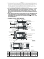
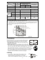
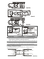
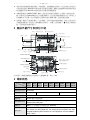
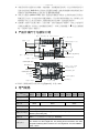
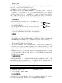
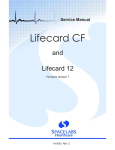
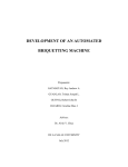
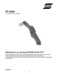
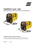
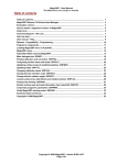
2009-06-15 5011668901-EH21 DVP-1070030-02 ΞΞΞΞΞΞΞΞΞΞΞΞΞΞΞΞΞΞΞΞΞΞΞΞΞ ENGLISH ΞΞΞΞΞΞΞΞΞΞΞΞΞΞΞΞΞΞΞΞΞΞΞΞΞ a This Instruction Sheet only provides descriptions for electrical specifications, general specifications, installation & wiring. Other detail infromation about programming and intructions, please see “DVP-PLC Application Manual: Programming”. For more information about the optional peripherals, please see individual product instuction sheet or “DVP-PLC Application Manual: Special I/O Modules”. a DVP-EH2 is an OPEN TYPE device and therefore should be installed in an enclosure free of airborne dust, humidity, electric shock and vibration. The enclosure should prevent non-maintenance staff from operating the device (e.g. key or specific tools are required for operating the enclosure) in case danger and damage on the device may occur. a Do NOT connect the AC main circuit power supply to any of the input/output terminals, or it may damage the PLC. Check all the wiring prior to power up. To prevent any electromagnetic noise, make sure the PLC is properly grounded . Do NOT touch terminals when power on. Product Profile & Dimension I/O term inal cover Input indicator I/O term inals Com munication port cover I/O m odule connection port cover DIN rail (35mm ) I/O term inal No. DIN rail clip Function card/ mem ory card cover Output indicator [ Figure 1 ] C OM 2 (R S-485) R un/Stop switch P OW ER /RU N/BAT.LOW/ E RR OR indicator VR0/VR 1 I/O m odule connection port C OM 1 (R S-232) Battery socket M ounting screw B attery D irect m ounting hole Function card m ounting hole Memory card port X2 90.0 80.0 4ˁ6 [ Figure 2 ] Unit: mm W1 W [ Figure 3 ] 82.2 Model name 16EH00 R2/T2 20EH00 32EH00 40EH00 R2/T2 R2/T2/M2 R2/T2 W 113 113 143.5 W1 103 103 133.5 48EH00 R2/T2 60EH00 T2 64EH00 R2/T2 80EH00 R2/T2 158.8 174 212 212 276 153.8 164 202 202 266 -1- Electrical Specifications Model Item 16EH 00 2 Power supply voltage 100 ~ 240VAC (-15% ~ 10%); 50/60Hz r 5% Fuse capacity 2A/250VAC Power consumption 20EH 00 2 32EH 00 2 32EH 00M2 50VA 40EH 00 2 48EH 00 2 60EH 00 2 60VA 64EH 00 2 80EH 00 2 80VA DC24V current output 500mA Power supply protection DC24V output short circuit protection Voltage withstand 1,500VAC (Primary-secondary), 1,500VAC (Primary-PE), 500VAC (Secondary-PE) Insulation resistance > 5Mȍ at 500VDC (between all I/O points and ground) ESD: 8KV Air Discharge EFT: Power Line: 2KV, Digital I/O: 1KV, Analog & Communication I/O: 250V Noise immunity Damped-Oscillatory Wave: Power Line: 1KV, Digital I/O: 1KV, RS: 26MHz ~ 1GHz, 10V/m Grounding The diameter of grounding wire shall not be less than that of L, N terminal of the power supply. (When many PLCs are in use at the same time, please make sure every PLC is properly grounded.) Operation/ storage Operation: 0°C~55°C (temperature), 50~95% (humidity), pollution degree 2 Storage: -25°C~70°C (temperature), 5~95% (humidity) Vibration/shock International standards: IEC61131-2, IEC 68-2-6 (TEST Fc)/ IEC61131-2 & resistance IEC 68-2-27 (TEST Ea) R: 500 R: 520 R: 652 T: 480 T: 500 T: 612 Weight (g) R: 710 R: 748 T: 675 T: 688 644 742 R: 836 R: 948 T: 756 T: 848 Input Point Spec. Items Two Differential inputs (200kHz) 24VDC single common port input 200kHz 20kHz Input wiring type Independent wiring Input indicator LED display; light on = ON, light off = OFF Input voltage (± 10%) Input point configuration Input impedance 10kHz Change wiring from S/S to SINK or SOURCE 5~24VDC 24VDC #1 #2 #3 #4 4.7K Ohm 4.7K Ohm 3.3K Ohm 4.7K Ohm Active Level Off ĺ On > 1mA (5V) > 4mA (16.5V) > 6mA (18.5V) > 4mA (16.5V) On ĺ Off < 0.4mA (2V) < 1.5mA (8V) < 2.2mA (8V) < 1.5mA (8V) Response time #5 Off ĺ On < 150ns < 150ns < 3.5ȝs < 8ȝs On ĺ Off < 3ȝs < 3ȝs < 20ȝs < 60ȝs #1: The frequency of differential input points X0, X1, X4, and X5 on DVP32EH00M2 is 200kHz. #2: The frequency of input points X0, X1, X4, and X5 is 200kHz. The frequency of input points X10, X11, X14 and X15 on DVP40/60EH2 is 200kHz. #3: The bandwidth of input points X10, X11, X14, and X15 is 20kHz (except for input points on DVP40/60EH2). #4: The bandwidth of the input points other than the high-speed input points listed above is 10kHz. #5: Input points X0 ~ X7and X10 ~ X17 can conduct 10 ~ 60ms digital filter adjustment. -2- Output Point Spec. Items Single common port transistor output Two differential outputs #1 Low speed 200kHz 10kHz Max. frequency Output indicator 200kHz Single common port relay output Load ON/OFF control LED display; light on = ON, light off = OFF 5VDC 5 ~ 30VDC 2mA/DC power l І250VAC, 30VDC Line Driver Photo coupler isolation Magnetic isolation Resistive < 25mA 0.5A/1 point (4A/COM) 2A/1 point (5A/COM) Inductive - 12W (24VDC) #3 Lamp - 2W(24VDC) 20WDC/100WAC Minimum load - Working voltage Insulation Maximum load High speed #2 Max. output response time OffOn: 20ȝs OnOff: 30ȝs 0.2ȝs 0.2ȝs Over-current protection 10ms N/A #1: DVP32EH00M2 support two differential outputs (Y0~Y3). #2: DVP20/32EH2 support high-speed output points (Y0, Y2); DVP40EH2 supports high-speed output points (Y0~ Y3, Y4, Y6); DVP60EH2 supports high-speed output points (Y0~Y3). Other DVP-EH2 models support only low-speed output. #3: Life curves 3000 120VAC Resistive 30VDC Inductive(t=7ms) 2000 240VAC Inductive(cosӿ= 0.4) Operation(X10 3 ) 1000 120VAC Inductive(cosӿ=0.4) 500 300 200 100 50 30 20 0.1 30VDC Inductive (t=40ms) 0.2 0.3 0.5 0.7 1 2 Contact Current(A) [ Figure 4 ] Installation Please install the PLC in an enclosure with sufficient space around it to allow heat dissipation, as shown in the figure. y Direct Mounting: Please use M4 screw according to the dimension of the product. y DIN Rail Mounting: When mounting the PLC to 35mm DIN rail, be sure to use the retaining clip to stop any side-to-side movement of the PLC and reduce the chance of wires being loose. The retaining clip is at the bottom of the PLC. To secure the PLC to DIN rail, pull down the clip, place it onto the rail and gently push it up. To remove the PLC, pull the retaining clip down with a flat screwdriver and gently remove the PLC from DIN rail, as shown in the figure. Wiring 1. Use O-type or Y-type terminal. See the figure in the right hand side for its specification. PLC terminal screws should be tightened to 9.50 kg-cm (8.25 in-Ibs) -3- Below 6.2 mm To suit M3.5 screw terminals Below 6.2 mm and please use only 60/75ºC copper conductor. 2. DO NOT wire empty terminal. DO NOT place the input signal cable and output power cable in the same wiring circuit. 3. DO NOT drop tiny metallic conductor into the PLC while screwing and wiring. Tear off the sticker on the heat dissipation hole for preventing alien substances from dropping in, to ensure normal heat dissipation of the PLC. Power Supply The power input type for DVP-EH2 series is AC input. When operating the PLC, please note the following points: 1. The input voltage should be current and its range should be 100 ~ 240VAC. The power should be connected to L and N terminals. Wiring AC110V or AC220V to +24V terminal or input terminal will result in serious damage on the PLC. 2. The AC power input for PLC MPU and I/O modules should be ON or OFF at the same time. 3. Use wires of 1.6mm (or longer) for the grounding of PLC MPU. The power shutdown of less than 10 ms will not affect the operation of the PLC. However, power shutdown time that is too long or the drop of power voltage will stop the operation of the PLC and all outputs will go OFF. When the power returns to normal status, the PLC will automatically resume operation. (Care should be taken on the latched auxiliary relays and registers inside the PLC when programming). 4. The +24V output is rated at 0.5A from MPU. DO NOT connect other external power supplies to this terminal. Every input terminal requires 6 ~ 7mA to be driven; e.g. the 16-point input will require approximately 100mA. Therefore, +24V terminal cannot give output to the external load that is more than 400mA. Safety Wiring In PLC control system, many devices are controlled at the same time and actions of any device could influence each other, i.e. breakdown of any device may cause the breakdown of the entire auto-control system and danger. Therefore, we suggest you wire a protection circuit at the power supply input terminal. See the figure below. 1 Ϥ AC power supply:100 ~ 240VAC, 50/60Hz 3 Ϥ Emergency stop: This button cuts off the system power supply when accidental emergency takes place. 4 Ϥ Power indicator 5 Ϥ AC power supply load 6 Ϥ Power supply circuit protection fuse (2A) 7 Ϥ DVP-PLC (main processing unit) 8 Ϥ DC power supply output: 24VDC, 500mA -4- 2 Ϥ Breaker Input Point Wiring There are 2 types of DC inputs, SINK and SOURCE. (See the example below. For detailed point configuration, please refer to the specification of each model.) y DC Signal IN – SINK mode Input point loop equivalent circuit +24V 24VDC 24G S/S X0 X1 [ Figure 6 ] y DC Signal IN – SOURCE mode Input point loop equivalent circuit +24V 24VDC 24G S/S X0 X1 [ Figure 7 ] Wiring of Differential Input X0 ~ X1 and X4 ~ X5 of DVP32EH00M2 are all high-speed input circuit and others are DC24V input. The working frequency of high-speed input circuit can reach up to 200kHz and is mainly for connecting to differential (double-wire) LINE DRIVER output circuit. y Wiring in a high-speed, high-noise environment DVP32EH00M2 high-speed input Encoder output A+ X0+ A A- X0- Twisted pair cable Differ ential output B+ X1+ B- X1- B [ Figure 8 ] In an environment with low noise and frequency less than 50kHz, use DC5V/DC24V single-ended SINK/SOURCE input. Wiring of DVP32EH00M2 DC5V/DC24V PNP SENSOR X0+ X0 - SINK *1 + 5V/24V X0+ *1 + 5V/24V SOURCE X0 - NPN SENSOR [ Figure 10 ] [ Figure 9 ] *1: The resistance is for 24V wiring only, 2K Ohm / 0.5W. -5- Output Point Wiring y Relay (R) output circuit wiring 1 Ϥ DC power supply 2 Ϥ 3 Ϥ Fuse: Uses 5 ~ 10A fuse at the shared terminal of output contacts to protect the output circuit 4 Ϥ Transient voltage suppressor: To extend the life span of contact. Emergency stop: Uses external switch 1. Diode suppression of DC load: Used when in smaller power (Figure 12) 2. Diode + Zener suppression of DC load: Used when in larger power and frequent On/Off (Figure 13) 5 Ϥ Incandescent light (resistive load) 6 Ϥ 7 Ϥ Manually exclusive output: For example, Y3 and Y4 control the forward running and reverse running of the motor, forming an interlock for the external circuit, together with the PLC internal program, to ensure safe protection in case of any unexpected errors. 8 Ϥ Neon indicator 9 Ϥ Absorber: To reduce the interference on AC load (Figure 14) y Transistor (T) output circuit wiring NPN type1: DVP16/20/32/48/64/80EH2 -6- AC power supply NPN type2: DVP40/60EH2 1 Ϥ 4 Ϥ 2 Ϥ DC power supply Emergency stop 3 Ϥ Circuit protection fuse The output of the transistor model is “open collector”. If Y0/Y1 is set to pulse output, the output current has to be bigger than 0.1A to ensure normal operation of the model. 1. Diode suppression: Used when in smaller power (Figure 19) 2. Diode + Zener suppression: Used when in larger power and frequent On/Off (Figure 20) 5 Ϥ Manually exclusive output: For example, Y10 and Y11 control the forward running and reverse running of the motor, forming an interlock for the external circuit, together with the PLC internal program, to ensure safe protection in case of any unexpected errors. Wiring of Differential Output y DVP32EH00M2 differential output with ASDA-A & A+, ASDA-A2 series driver DVP32EH00M2 differ ent ial output Dr iver Y0+ /P LS 43 Y0 Y0SG0 PLS 41 Cir cuit for Photocouple Twisted pair cable Y1+ /S IGN 36 Y1- SI GN 37 Y1 Circuit for Photocouple [ Figure 21 ] -7- y DVP32EH00M2 differential output with ASDA-B series driver DVP32EH00M2 differ ent ial output Dr iver Y0+ /P LS 21 Cir cuit for Photocouple Y0 Y0SG0 PLS 22 Twisted pair cable Y1+ /S IGN 19 Y1- SI GN 20 Circuit for Photocouple Y1 [ Figure 22 ] y DVP32EH00M2 differential output with ASDA-AB series driver DVP32EH00M2 differential output Dr iver Y0+ PLS 43 Y0- /P LS 41 Y0 SG0 Cir cuit for Photocouple Twisted pair cable Y1+ SI GN 36 Y1- /SIGN 37 Y1 Cir cuit for Photocouple [ Figure 23 ] BAT.LOW indicator BAT.LOW indicator will be on when the battery is in low voltage. When this happens, change the battery as soon as possible in case your program and data saved in the latched area will be lost. After the power is switched off, the data in the latched area are stored in SRAM memory and its power is supplied by the battery. Therefore, when the battery is in low voltage and the power-off has been lasted for more than 1 minute, the data in the latched area will be lost. If you need to permanently save the data in the latched area in the program and device D, refer to “Flash ROM permanently saved and recover mechanism” as stated below. Permanently saved mechanism You can use WPLSoft (Options -> PLC<=>Flash) to indicate whether to permanently store the data in the latched area in Flash ROM memory (new indicated data will replace all data previously saved in the memory). Recover mechanism If the battery is in low voltage (before the power is switched off when the BAT.LOW indicator is on) and the power is off for more than 1 minute, PLC will automatically restore the data in the latched area in the program and device D of Flash ROM into SRAM memory next time when it is re-powered. Battery Life Temperature (ºC) 0 25 50 70 Life (year) 9 8 6 5 Accuracy (month/second) of RTC Temperature (ºC/ºF) 0/32 25/77 55/131 Max. inaccuracy (second) -117 52 -132 -8- ΞΞΞΞΞΞΞΞΞΞΞΞΞΞΞΞΞΞΞΞΞΞΞΞΞ ᧯խ֮ ΞΞΞΞΞΞΞΞΞΞΞΞΞΞΞΞΞΞΞΞΞΞΞΞΞΞΞ a شࠌءᎅࣔႛ༼ࠎሽΕפ౨ΕڜᇘᒵຝٝᎅࣔΔࠡ،ᇡาհ࿓ڤૠ ֗ਐחᎅࣔᓮߠ DVP-PLC ᚨݾش֫םμ࿓ڤᒧν Δᙇհၜᢰᇘᆜᇡาᎅࣔᓮߠᇠ ขᙟᖲ֫ ࢨםDVP-PLC ᚨݾش֫םμᑓิᒧνΖ a ءᖲၲ࣋ী (OPEN TYPE) ᖲླྀΔءشࠌृشࠌڼڂᖲழΔؘႊലհڜᇘ࣍ࠠ ቺΕᑪ֗࣍܍ሽᚰ/ᓢᚰრ؆հ؆ླྀᒵᒣփΖؘႊࠠໂঅᥨൻਜΰڕΚհՠ ࠠࢨᨤೲթؚױၲαַॺፂᥨԳᖙࢨ܂რ؆ᓢᚰ᧯ءΔທٲګᙠ֗ჾᡏΖ a ٌੌᙁԵሽᄭլױຑ൷࣍ᙁԵЯॾנᇆጤΔܡঞױ౨ທګᣤૹჾᡏΔᓮڇՂሽհছ٦ ڻᒔᎁሽᄭᒵΖᓮ֎ڇՂሽழᤛٚ۶ጤΖ᧯ءՂհ൷چጤ ೭إؘᒔऱ൷ چΔ༼ױขݼᠧಛ౨ԺΖ !யݡγ៍͎̇ᄃొҜ̬! ᙁԵ Яᙁ נጤ ። ᙁԵ រਐ قᗉ ᙁԵ Яᙁ נጤ ຏಛ ՑՂ። I/O ᑓิ ຑ൷ ՑՂ። ࡐࡳʳD IN ૩ ᜊ (35m m) ᙁԵ Яᙁ נጤ ᒳᇆ D IN ૩ࡐ ࡳڬ פ౨ Яಖ ᖋ Ղ። ᙁ נរਐ قᗉ C OM 2 (R S-485) R un/Stop ၲ ᣂ ሽᄭ Εሎ۩ Εᙑ ᎄ ֗ ሽ ۃणኪ ਐق VR0/VR 1 I/O ᑓิ ຑ൷ Ց C OM 1 (R S-232) ሽ༺ ۃᑒ ᖲߪ ࡐࡳᝅ ሽۃ ऴ൷ ࡐࡳ֞ פ౨ ֞ ࡳࡐ ಖᖋ ༺ᑒ y ᇡา֡՚ቹ।ᓮᔹ֮ठᒘ 1 հ[Figure 3]ΔۯΚmmΖ !ঈఢॾ! ᖲጟ 16EH 20EH 32EH 32EH 40EH 48EH 60EH 64EH 80EH ႈؾ 00 2 00 2 00 2 00M2 00 2 00 2 00 2 00 2 00 2 ሽᄭሽᚘ 100 ~ 240VAC (-15% ~ 10%); 50/60Hz r 5% ሽᄭঅᙠ୲ၦ 2A/250VAC פ 50VA 60VA 80VA DC24V ሽੌᙁ נ500mA ሽᄭঅᥨ ડंሽᚘર࠹ၦ DC24V ᙁࠠנሁঅᥨ 1,500VAC (Primary-secondary), 1,500VAC (Primary-PE), 500VAC (Secondary-PE) ᒴॴݼ 5Mȍ אՂ (ࢬڶᙁנ/Եរኙچհၴ 500VDC) ᠧಛ܍Ժ ESD: 8KV Air Discharge EFT: Power Line: 2KV, Digital I/O: 1KV, Analog & Communication I/O: 250V Damped-Oscillatory Wave: Power Line: 1KV, Digital I/O: 1KV, RS: 26MHz ~ 1GHz, 10V/m -9- ᖲጟ 16EH 20EH 32EH 32EH 40EH 48EH 60EH 64EH 80EH ႈؾ 00 2 00 2 00 2 00M2 00 2 00 2 00 2 00 2 00 2 ൷چ ൷چᒵհᒵஉլ՛࣍ሽᄭጤ L, N հᒵஉΰ ڍPLC ٵழࠌشழΔᓮ೭ ؘរ൷چα ᖙ܂/ᚏژᛩቼ ᖙ܂Κ0°C ~55°C (ᄵ৫)Δ50 ~ 95% (ᛘ৫)Δۆ్ 2 ᚏژΚ-25°C ~70°C (ᄵ৫)Δ5 ~ 95% (ᛘ৫α ഏᎾᑑᄷᒤ IEC61131-2, IEC 68-2-6 (TEST Fc)/ IEC61131-2 & IEC 68-2-27 (TEST Ea) ર೯/ᓢᚰ R: 500 R: 520 R: 652 ૹၦ (g) T: 480 T: 500 T: 612 R: 710 R: 748 644 T: 675 R: 836 R: 948 742 T: 688 T: 756 T: 848 ᙁԵរ ႈؾ ᙁԵ൷ᒵীڤ ᠨጤ೯ᙁԵ (200kHz) طጤ S/S ᧢ང൷ᒵ SINK ࢨ SOURCE 5~24VDC 24VDC #2 #3 #4 4.7K Ohm 4.7K Ohm 3.3K Ohm 4.7K Ohm OffOn > 1mA (5V) > 4mA (16.5V) > 6mA (18.5V) > 4mA (16.5V) OnOff < 0.4mA (2V) < 1.5mA (8V) < 2.2mA (8V) < 1.5mA (8V) OffOn < 150ns < 150ns < 3.5ȝs < 8ȝs OnOff < 3ȝs < 3ȝs < 20ȝs < 60ȝs ᙁԵॴݼ ᠧಛࠫލ 10kHz #1 ᙁԵរᆜ #5 20kHz LED ᧩قΙᗉॽ।ق ONΔլॽ।ق OFF ᙁԵॾᇆሽᚘ(±10%) ֘ᚨழၴ 200kHz ᗑم൷ᒵ ᙁԵ೯܂ਐق ೯ۯ܂ 24VDC ጤ٥រᙁԵ #1ΚDVP32EH00M2 ᠨጤ೯ᙁԵរ X0, X1, X4, X5 ᙮ױ 200kHzΖ #2ΚᙁԵរ X0, X1, X4, X5 հ᙮ױ 200kHzΙDVP40/60EH2 ᙁԵរ X10, X11, X14, X15 հ᙮ױ 200kHzΖ #3ΚᙁԵរ X10, X11, X14, X15 հ᙮ᐈ 20kHz (DVP40/60EH2 ೈ؆) Ζ #4ΚೈՂ૪ᎅࣔຒᙁԵរհ؆Δࠡ塒ᙁԵ 10kHzΖ #5ΚᙁԵរ X0~X17 ܂ױ10~60ms ᑇۯៀंᓳᖞΖ ᙁנរ ႈؾ ٌ່ང(ՠ)܂᙮ ᠨጤ೯ᙁנ #1 200kHz ᙁנ೯܂ਐق ጤ٥រሽདྷ᧯ᙁנ ܅ຒ 10kHz ຒ #2 200kHz ጤ٥រᤉሽᕴᙁנ ሉ ON/OFF ൳ࠫࠌش LED ᧩ق, ᗉॽ।ق’ON’, լॽ।ق’OFF’ ່՛ሉ 2mA/DC ሽᄭ - ՠ܂ሽᚘ 5VDC 5 ~ 30VDC І250VAC, 30VDC ሶᠦֱڤ ᦀ೯్ሽᄭሶᠦ ٠ᓀٽሶᠦ ሽࢤሶᠦ ሽॴࢤ < 25mA 0.5A/1 រ (4A/COM) 2A/1 រ (5A/COM) ሽტࢤ - 12W (24VDC) #3 ᗉऐ - 2W(24VDC) 20WDC/100WAC ሽੌ ່Օᙁנ OffOn ᙈழၴ OnOff 0.2ȝs 20ȝs 0.2ȝs 10ms 30ȝs ᙁנመሽੌঅᥨ N/A #1ΚDVP32EH00M2 ֭གᠨጤ೯ᙁ(נY0~Y3)Ζ #2ΚDVP20/32EH2 ֭གຒᙁנរ(Y0,Y2)ΙDVP40EH2 ֭གຒᙁנរ(Y0~Y3,Y4,Y6)Ι DVP60EH2 ֭གຒᙁנរ(Y0~Y3)Ιࠡ הEH2 ᖲጟ֭ག܅ຒᙁנΖ #3Κࡎسၜཚڴᒵቹᓮᔹ֮ठ[Figure 4]Ζ - 10 - щ྅͞ё PLC ڜڇᇘழΔᓮᇘ࣍ຨڤհ൳ࠫᒣփΔࠡࡌᚨঅԫࡳհ़ၴΔאᒔঅ PLC ཋ ᑷפ౨إൄΔᓮᔹ֮ठᒘ 3 հᆜقრቹΖ y ऴ൷᠙ᢽֱڤΚᓮࠉข؆ী֡՚ࠀࠌ شM4 ᢽΖ y DIN ᔱ૩հڜᇘֱऄΚᔞ ࣍ش35mm հ DIN ᔱ૩ΖڇലᖲՂᔱ૩ழΔᓮ٣ലᖲ ΰࢨ I/O ᑓิαՀֱհࡐࡳႿᓄׂΔאԫݮڗದ༺Եןᑒࠀٻ؆ᐶၲࢮנΰᓮᔹ ֮ठᒘ 3 հቹقα Δ٦ലᖲΰࢨ I/O ᑓิαՂᔱ૩Δհ৵ലࡐࡳႿᓄׂᚘװڃڬ ױܛΖ࠷ՀᖲழΔٵᑌאԫݮڗದ٣ലࡐࡳႿᓄׂᐶၲΔ٦ലᖲא؆ٻՂऱ ֱױܛנ࠷ڤΖᇠࡐࡳᖲዌႿᓄׂঅীΔڼڂᐶၲ৵ঁլᄎᐘװڃΖ ੨ቢბ̄ 1. ᙁנ/Եᒵጤᓮࠌ شO ীࢨ Y ীጤΔጤࢬؐڕ قΖPLC ጤᢽށԺ 9.50 kg-cm (8.25 in-lbs)Ζ౨ ࠌ ش60/75°C ऱᎭᖄᒵΖ 2. ़ጤᓮ֎ᒵΖᙁԵរॾᇆᒵፖᙁנរ೯Ժᒵᓮ֎ᆜ ࣍ٵԫᒵᜊփΖ 6.2 mm אՀ M3.5 ࠌش 6.2 mm אՀ 3. ᠙ᢽ֗ᒵழᓮᝩ܍პ՛ऱ८᥆ᖄ᧯ൾԵ PLC փຝΔࠀڇᒵګݙ৵Δല ࣍ۯPLC Ղֱཋᑷ֞ۯᆜऱฆढൾԵհ၀ᐺװΔאঅཋᑷߜړΖ ბ DVP-EH2 ߓ٨ PLC ሽᄭᙁԵٌੌᙁԵΔشࠌڇՂᚨࣹრՀ٨ࠃႈΚ 1. ٌੌሽᄭᙁԵሽᚘΔᒤᐈᐖΰ100 ~ 240VACα Δሽᄭᓮ൷࣍ LΕN ࠟጤΔ࣠ڕല AC110V ࢨ AC220V ൷۟+24V ጤࢨᙁԵរጤΔലທ ګPLC ᣤૹჾᡏΔᓮࠌृشܑࣹრΖ 2. ᖲ֗ I/O ᑓิհٌੌሽᄭᙁԵᓮٵழ ܂On ࢨ Off ऱ೯܂Ζ 3. ᖲհ൷چጤࠌ ش1.6mm אՂհሽᒵ൷چΖ 4. ᅝೖሽழၴ ࣍܅10ms ழΔPLC լ࠹ᐙᤉᥛሎ᠏Δᅝೖሽழၴመ९ࢨሽᄭሽᚘՀ૾ ലࠌ PLC ೖַሎ᠏Δᙁנ٤ຝ OffΔᅝሽᄭ༚إൄழΔPLC ٍ۞೯ڃ༚ሎ᠏Ζ ΰPLC փຝࠠڶೖሽঅऱ᎖ܗᤉሽᕴ֗ᑉژᕴΔࠌ܂ڇृش࿓ڤૠቤழᚨܑࣹრࠌ شΖα 5. +24V ሽᄭࠎᚨᙁנጤΔ່Օ 0.5AΔᓮ֎ലࠡהऱ؆ຝሽᄭຑ൷۟ڼጤΖޢଡᙁ Եរᦀ೯ሽੌؘႊ 6 ~ 7mAΔૉ א16 រᙁԵૠጩΔՕપᏁ 100mAΔڼڂ+24V ᙁנ ؆ຝሉլױՕ࣍ 400mAΖ щБ੨ቢаྮ ࣍طPLC ൳ࠫڍᇘᆜΔٚԫᇘᆜऱ೯ױ܂౨ຟᄎᐙࠡ،ᇘᆜऱ೯܂Ζڼڂٚԫᇘᆜ ऱਚᎽຟױ౨ᄎທګᖞଡ۞೯൳ࠫߓอ؈൳Δ۟ທٲګᙠΖࢬڇאሽᄭጤᙁԵڃሁΔ৬ ᤜऱঅᥨڃሁᆜቹᓮᔹ֮ठᒘ 4 հ[Figure 5]ࢬقΚ 1 Ϥ ٌੌሽᄭࠎᚨΚ100 ~ 240VAC, 50/60Hz 2 Ϥ 3 Ϥ ጹ৺ೖַΚቃડ࿇णउ࿇سΔᆜጹ৺ೖַਊၨΔڇױणउ࿇سழΔ֊ឰߓอሽᄭΖ 4 Ϥ ሽᄭਐقᗉ 5 Ϥ ٌੌሽᄭሉ 6 Ϥ ሽᄭڃሁঅᥨشঅᙠΰ2Aα 7 Ϥ DVP PLC ᖲ᧯ء 8 Ϥ ऴੌሽᄭࠎᚨᙁנΚ24VDCΔ500mA ឰሁᕴ Ꮾˢᕇ̝੨ቢ ᙁԵរհԵԺॾᇆऴੌሽᄭ DC ᙁԵΔDC ীڤ٥ࠟڶጟ൷ऄΚSINK ֗ SOURCEΔࠡ ࡳᆠፖᙁԵរڃሁயሽሁᒵቹΔᓮᔹ֮ठᒘ 5 հ[Figure 6]֗[Figure7]Ζ - 11 - मજᏮˢ̝੨ቢ DVP32EH00M2 հ X0 ~ X1 ֗ X4 ~ X5 ݁ DC5~24V ຒᙁԵሽሁΰࠡ塒ঞ DC24V ᙁԵαΖڼຒᙁԵሽሁՠ܂᙮ױሒ 200kHzΔএאشຑ൷೯ΰᠨᒵڤαLINE DRIVER ᙁנሽሁشΖ y ೯ᙁԵհ൷ᒵቹΰຒΕᠧಛழࠌشα DVP32EH00M2 ຒᙁԵ ᒳᒘᕴᙁנ A+ X0+ A A- X0- ೯ᙁנ ᠨᒵ B+ X1+ B- X1- B ڇᠧಛለ܅᙮՛࣍ 50kHz հᛩቼՀΔࠌ شDC5V/ DC24V ጤհ SINK/SOURCE ᙁ ԵΔᇡา൷ᒵቹᓮᔹ֮ठᒘ 5 հ[Figure 9]֗[Figure 10]Ζ Ꮾᕇ̝੨ቢ y ᤉሽᕴᙁڃנሁᒵ 1 Ϥ ऴੌሽᄭࠎ 2 Ϥ 3 Ϥ অᙠΚࠌ ش5 ~ 10A ऱঅᙠ୲ၦ࣍ᙁנ൷រऱ٥شរΔঅᥨᙁנរڃሁ 4 Ϥ ડंگܮԲᄕ᧯Κױᏺף൷រኂࡎΖ ጹ৺ೖַΚࠌش؆ຝၲᣂ 1. DC ሉሽᄭհԲᄕ᧯ࠫލΚפለ՛ழࠌشΰᓮᔹ֮ठᒘ 6 հ[Figure 12]α 2. DC ሉሽᄭհԲᄕ᧯+Zener ࠫލΚՕפ On/Off ᙮ழࠌ شΰᓮᔹ֮ठᒘ 6 հ[Figure 13]α 5 Ϥ ػᗅᗉΰሽॴࢤሉα 6 Ϥ 7 Ϥ յ؞ᙁנΚࠏڕΔല Y3 ፖ Y4 אش൳ࠫኙᚨ್ሒऱإ᠏֗֘᠏Δࠌ؆ຝሽሁګݮյ᠙Δ ٽPLC փຝ࿓ڤΔᒔঅٚ۶ฆൄડ࿇णउ࿇سழΔ݁ڜڶ٤ऱঅᥨൻਜΖ 8 Ϥ ਐقᗉΚھᗉ 9 Ϥ ડंگܮᕴΚੌٌ֟྇ױሉՂऱᠧಛΰᓮᔹ֮ठᒘ 6 հ[Figure 14]α ٌੌሽᄭࠎ y ሽདྷ᧯ᙁڃנሁᒵ NPN ী ڤ1ΚDVP16/20/32/48/64/80EH2 ሉ LED ! ᤛ ࿇ ڃ ሁ Y0 < 0.3A C0 ሽདྷ᧯ᙁנ ᇡาᒵቹᓮᔹ֮ठᒘ 7 հ[Figure 16]Ζ - 12 - NPN ী ڤ2ΚDVP40/60EH2 24VDC UP0 ሉ LED ! Y0 ᤛ ࿇ ڃ ሁ < 0.3A ZP0 ሽདྷ᧯ᙁנ ᇡาᒵቹᓮᔹ֮ठᒘ 7 հ[Figure 18]Ζ 1 Ϥ 4 Ϥ 2 Ϥ ऴੌሽᄭࠎᚨ 3 Ϥ ጹ৺ೖַ ሽሁڃሁঅᥨشঅᙠ ڂሽདྷ᧯ᑓิᙁ݁נၲႃᄕᙁ( נOpen Collector)Δૉ Y0/Y1 ࡳ౧ंۭᙁנΔᒔ অሽདྷ᧯ᑓิ౨ജ೯إ܂ൄΔࠡᙁ֒༼נሽॴΔؘႊፂᙁנሽੌՕ࣍ 0.1AΖ 1. Բᄕ᧯ࠫލΚפለ՛ழࠌشΰᓮᔹ֮ठᒘ 7 հ[Figure 19]α 2. Բᄕ᧯+Zener ࠫލΚՕפ On/Off ᙮ழࠌشΰᓮᔹ֮ठᒘ 7 հ[Figure 20]α 5 Ϥ յ؞ᙁנΚࠏڕΔല Y10 ፖ Y11 אش൳ࠫኙᚨ್ሒऱإ᠏֗֘᠏Δࠌ؆ຝሽሁګݮյ᠙Δ ٽPLC փຝ࿓ڤΔᒔঅٚ۶ฆൄડ࿇णउ࿇سழΔ݁ڜڶ٤ऱঅᥨൻਜΖ मજᏮ̝੨ቢ y DVP32EH00M2 ೯ᙁנፖ ASDA-A & A+ΕASDA-A2 ߓ٨ᦀ೯ᕴ ᇡาᒵቹᓮᔹ֮ठᒘ 7 հ[Figure 21]Ζ y DVP32EH00M2 ೯ᙁנፖ ASDA-B ߓ٨ᦀ೯ᕴ ᇡาᒵቹᓮᔹ֮ठᒘ 8 հ[Figure 22]Ζ y DVP32EH00M2 ೯ᙁנፖ ASDA-AB ߓ٨ᦀ೯ᕴ ᇡาᒵቹᓮᔹ֮ठᒘ 8 հ[Figure 23]Ζ Ѱ BAT.LOW ϯ፶ ᅝሽۃሽᚘመ ࠌ܅BAT.LOW ਐقᗉॽದழΔᓮᕣຒޓངሽאۃᝩृشࠌ܍࿓֗ڤೖሽঅ ᇷற؈ΖڇሽᄭՀሽ৵Δೖሽঅऱᇷறઃ ࣍࣋ژSRAM ಖᖋ᧯խΔڼழطሽ ࠎ༼ۃፂ SRAM փᇷறऱሽᄭΔਚᅝሽۃሽԺլߩՀሽ৵ሒ 1 ։ᤪאՂழΔࠡ࿓ڤ ፖೖሽঅհᇷறലᄎ؈ΖڼڂΔૉ࿓ڤૠृᏁല࿓ڤፖ D ᇘᆜೖሽঅ ةՆঅژழΔᓮᅃՀ૪ Flash ROM ةՆঅፖڃ༚ᖲࠫΖ ةՆঅᖲࠫΚ ࿓ڤૠृ شࠌױWPLSoft ຌ᧯༼ࠎհࡳᙇႈΰ”ࡳ”--> “PLC<=>Flash”αࠐਐࡳ࿓ ڤ֗ D ᇘᆜೖሽঅऱᇷறਢةܡՆঅ۟ Flash ROM ಖᖋ᧯խΖڻޢਐࡳ৵հᇷ றലᄎ።ൾছ ࣍ژڻFlash ROM փऱࢬڶᇷறΖ ڃ༚ᖲࠫΚ ᅝሽۃሽԺլߩΰܛሽᄭՀሽছሽ܅ۃሽᚘᗉॽαΔሽᄭՀሽሒ 1 ։ᤪאՂழΔঞ PLC փຝᄎڇՀڻሽᄭՂሽழΔ۞೯ല Flash ROM փհ࿓ڤፖ D ᇘᆜೖሽঅऱᇷறΔ ٤ຝ ۟ژڃSRAM ಖᖋ᧯խΖ Ѱု ᄵ৫ (°C) 0 25 50 70 ኂࡎ ()ڣ 9 8 6 5 ༱ѐፌ۞ჟޘĞ͡Ɲࡋğ ᄵ৫ (°C/°F) 0/32 25/77 55/131 ່Օᎄΰઞα -117 52 -132 - 13 - ΞΞΞΞΞΞΞΞΞΞΞΞΞΞΞΞΞΞΞΞΞΞΞΞΞΞ ㅔԧЁ᭛ ΞΞΞΞΞΞΞΞΞΞΞΞΞΞΞΞΞΞΞΞΞΞΞΞΞ a شࠌء円ࣔ䢰㡖༼ࠎ䶣ᩥ億Εפ౨億Εڜ僞优ຝٝ円ࣔΔࠡ،典伟ऱ࿓ݧ児儳 ֗ਐח円ࣔ冉儁 DVP-PLC 䬗ݾش㢜֫㡸μ࿓ݧᒧνΔ㳪凢؆䨜僞ᆜ典伟円ࣔ冉儁具䣈 䃘֫㡸ࢨ DVP-PLC 䬗ݾش㢜֫㡸μᑓ㥌ᒧνΖ a ء䢠䬞࣋ী (OPEN TYPE) ẊΔءشࠌृشࠌڼڂ㦍Δؘ和㰒ऱڜ僞Պࠠ㣟Ε ᑪ֗܍Պ䶣䥄Я㢿䥄რ؆ऱ؆㨆优ᒣ㡕Ζؘ和ࠠ䩥অ䮍ൻਜΰڕΚऱՠࠠ ࢨ匫ೲթؚױ䬞αַॺ位䮍Գ䦱ᖙࢨ܂რ؆㢿䥄ءΔທٲګ呐֗䮦݅Ζ a ٌੌ剽Ե䶣ᄭլױ劖൷Պ剽ԵЯॾנ㢆ጤΔܡ䥉ױ౨ທګ䢘ૹ䮦݅Δ冉ڇՂ䶣ऱছ٦ ┛ڻ儶䶣ᄭ优Ζ冉֎ڇՂ䶣㦍⡣ٚ۶ጤΖءՂऱ൷چጤ 䥜┛إؘऱ൷ چΔ༼ױ䣈ݼե᭯౨ԺΖ !யݡγ៍͎̇ᄃొҜ̬! 䕧ܹˋ 䕧ߎッᄤⲪ 䕧ܹ⚍ ᣛ⼎♃ 䕧ܹˋ 䕧ߎッᄤ ຏಛ ՑՂ። I/O ഫ 䖲 ষ Ϟ Ⲫ ᅮ DIN 䔼 ㊳ (35m m) 䕧ܹˋ 䕧ߎッᄤ㓪 ো D IN 䔼 ᅮ ᠷ ࡳ㛑व ˋ䆄ᖚवϞ Ⲫ 䕧ߎ⚍ ᣛ⼎♃ C OM 2 (RS -485) R un/Stop ᓔ ݇ ⬉⑤ǃ 䖤㸠ǃ䫭䇃 ঞ⬉∴ ⢊ᗕᣛ⼎ V R0/VR1 I/O ഫ 䖲 ষ C OM 1 (R S-232) ⬉∴ᦦ ῑ ᴎ䑿 ᅮ㶎ϱ ⬉∴ Ⳉ ᅮᄨ ࡳ㛑व ᅮᄨ 䆄ᖚव ᦦῑ y 䆺㒚ሎᇌ䇋খ䯙㣅᭛⠜义ⷕ 1 П[Figure 3]ˈऩԡ˖mmDŽ !ঈఢॾ! ᴎ⾡ 16EH 20EH 32EH 32EH 40EH 48EH 60EH 64EH 80EH 乍Ⳃ 00 2 00 2 00 2 00M2 00 2 00 2 00 2 00 2 00 2 ⬉⑤⬉य़ 100 ~ 240VAC (-15% ~ 10%); 50/60Hz r 5% ⬉⑤ֱ䰽ϱᆍ䞣 2A/250VAC ⍜㗫ࡳ⥛ 50VA 60VA 80VA DC24V ⬉⌕䕧ߎ 500mA ⬉⑤ֱᡸ DC24V 䕧ߎⷁ䏃ֱᡸ さ⊶⬉य़ᡓফ䞣 1,500VAC (Primary-secondary), 1,500VAC (Primary-PE), 500VAC (Secondary-PE) 㒱㓬䰏ᡫ 5Mȍ ҹϞ (᠔᳝䕧ߎ/ܹ⚍ᇍഄП䯈 500VDC) ᑆᡄ⭿ܡ ESD: 8KV Air Discharge EFT: Power Line: 2KV, Digital I/O: 1KV, Analog & Communication I/O: 250V Damped-Oscillatory Wave: Power Line: 1KV, Digital I/O: 1KV, RS: 26MHz ~ 1GHz, 10V/m - 14 - ᴎ⾡ 16EH 20EH 32EH 32EH 40EH 48EH 60EH 64EH 80EH 乍Ⳃ 00 2 00 2 00 2 00M2 00 2 00 2 00 2 00 2 00 2 ഄ ഄ䜡㒓ⱘ㒓ᕘϡᕫᇣѢ⬉⑤ッ L, N ⱘ㒓ᕘ˄ৄ PLC ৠᯊՓ⫼ᯊˈ䇋ࡵ ᖙऩ⚍ഄ˅ ᪡/ټᄬ⦃๗ ᪡˖0°C ~55°C (⏽ᑺ)ˈ50 ~ 95% (ᑺ)ˈ∵ᶧㄝ㑻 2 ټᄬ˖-25°C ~70°C (⏽ᑺ)ˈ5 ~ 95% (ᑺ) 䰙ᷛޚ㾘㣗 IEC61131-2, IEC 68-2-6 (TEST Fc)/ IEC61131-2 & IEC 68-2-27 (TEST Ea) 㗤ᤃࡼ/ߏކ R: 500 R: 520 R: 652 䞡䞣 (g) T: 480 T: 500 T: 612 R: 710 R: 748 644 T: 675 R: 836 R: 948 742 T: 688 T: 756 T: 848 䕧ܹ⚍㾘Ḑ 㾘Ḑ 乍Ⳃ 䕧ܹ㒓ൟᓣ ঠッᏂࡼ䕧ܹ (200kHz) 24VDC ऩッ݅⚍䕧ܹ 200kHz ⣀ゟ㒓 䕧ܹࡼᣛ⼎ 20kHz 10kHz ⬅ッᄤ S/S বᤶ㒓Ўⓣൟ⑤ൟ LED ᰒ⼎˗♃҂㸼⼎Ў ONˈϡ҂㸼⼎Ў OFF 䕧ֵܹো⬉य़(±10%) 䕧ܹ⚍䜡㕂 䕧ܹ䰏ᡫ 5~24VDC 24VDC #1 #2 #3 #4 4.7K Ohm 4.7K Ohm 3.3K Ohm 4.7K Ohm ࡼ OffOn > 1mA (5V) > 4mA (16.5V) > 6mA (18.5V) > 4mA (16.5V) Ј⬠⚍ OnOff < 0.4mA (2V) < 1.5mA (8V) < 2.2mA (8V) < 1.5mA (8V) OffOn < 150ns < 150ns < 3.5ȝs < 8ȝs OnOff < 3ȝs < 3ȝs < 20ȝs < 60ȝs ডᑨᯊ䯈 ᑆᡄᡥࠊ #5 #1˖DVP32EH00M2 ঠッᏂࡼ䕧ܹ⚍ X0, X1, X4, X5 乥⥛ৃЎ 200kHzDŽ #2˖䕧ܹ⚍ X0, X1, X4, X5 ⱘ乥⥛ৃЎ 200kHz˗DVP40/60EH2 䕧ܹ⚍ X10, X11, X14, X15 ⱘ乥⥛ৃЎ 200kHzDŽ #3˖䕧ܹ⚍ X10, X11, X14, X15 ⱘ乥ᆑЎ 20kHz (DVP40/60EH2 䰸) DŽ #4˖䰸Ϟ䗄䇈ᯢ催䗳䕧ܹ⚍Пˈ݊ԭ䕧ܹЎ 10kHzDŽ #5˖䕧ܹ⚍ X0~X17 ৃ 10~60ms ᭄ᄫⒸ⊶䇗ᭈDŽ 䕧ߎ⚍㾘Ḑ 㾘Ḑ 乍Ⳃ ᳔催Ѹᤶ(Ꮉ)乥⥛ ঠッᏂࡼ䕧ߎ #1 200kHz 䕧ߎࡼᣛ⼎ ऩッ݅⚍ԧㅵ䕧ߎ Ԣ䗳 10kHz 催䗳 #2 200kHz ऩッ݅⚍㒻⬉఼䕧ߎ 䋳䕑 ON/OFF ࠊՓ⫼ LED ᰒ⼎, ♃҂㸼⼎Ў’ON’, ϡ҂㸼⼎Ў’OFF’ ᳔ᇣ䋳䕑 2mA/DC ⬉⑤ - Ꮉ⬉य़ 5VDC 5 ~ 30VDC ˘250VAC, 30VDC 䱨⾏ᮍᓣ 偅ࡼ㑻⬉⑤䱨⾏ ܝ㗺ড়䱨⾏ ⬉⺕ᗻ䱨⾏ ⬉䰏ᗻ < 25mA 0.5A/1 ⚍ (4A/COM) 2A/1 ⚍ (5A/COM) ⬉ᛳᗻ - 12W (24VDC) #3 ♃⊵ - 2W(24VDC) 20WDC/100WAC ⬉⌕㾘Ḑ ᳔䕧ߎ OffOn ᓊ䖳ᯊ䯈 OnOff 0.2ȝs 20ȝs 0.2ȝs 10ms 30ȝs 䕧ߎ䖛⬉⌕ֱᡸ N/A #1˖DVP32EH00M2 ᬃᣕঠッᏂࡼ䕧ߎ(Y0~Y3)DŽ #2˖DVP20/32EH2 ᬃᣕ催䗳䕧ߎ⚍(Y0,Y2)˗DVP40EH2 ᬃᣕ催䗳䕧ߎ⚍(Y0~Y3,Y4,Y6)˗ DVP60EH2 ᬃᣕ催䗳䕧ߎ⚍(Y0~Y3)˗݊ᅗ EH2 ᴎ⾡াᬃᣕԢ䗳䕧ߎDŽ #3˖⫳ੑ਼ᳳ᳆㒓䇋খ䯙㣅᭛⠜[Figure 4]DŽ - 15 - !щ྅͞ё! PLC ᅝ㺙ᯊˈ䇋㺙䜡Ѣᇕ䯁ᓣⱘࠊㆅ਼݊ˈݙೈᑨֱᣕϔᅮⱘぎ䯈ˈҹ⹂ֱ PLC ᬷ ⛁ࡳ㛑ℷᐌΔ䇋খ䯙㣅᭛⠜义ⷕ 3 ⱘ䜡㕂⼎ᛣDŽ y Ⳉ䫕䬭ϱᮍᓣ˖䇋ձѻકൟሎᇌᑊՓ⫼ M4 䬭ϱDŽ y DIN 䪱䔼ⱘᅝ㺙ᮍ⊩˖䗖⫼Ѣ 35mm ⱘ DIN 䪱䔼DŽᇚЏᴎᣖϞ䪱䔼ᯊˈ䇋ܜᇚЏᴎ ˄ I/O ഫ˅ϟᮍⱘᅮล᭭⠛ˈҹϔᄫᔶ䍋ᄤᦦܹߍῑᑊᩥᓔᢝߎ˄䇋খ䯙㣅 ᭛⠜义ⷕ 3 ⱘ˅ق ˈݡᇚЏᴎ˄ I/O ഫ˅ᣖϞ䪱䔼ˈПৢᇚᅮล᭭⠛य़ᠷಲএ ेৃDŽ℆পϟЏᴎᯊˈৠḋҹϔᄫᔶ䍋ᄤܜᇚᅮล᭭⠛ᩥᓔˈݡᇚЏᴎҹᕔϞⱘ ᮍᓣপߎेৃDŽ䆹ᅮᴎᵘล᭭⠛Ўֱᣕൟˈℸᩥᓔৢ֓ϡӮᔍಲএDŽ ! !੨ቢბ̄! 1. 䕧ߎ/ܹ䜡㒓ッ䇋Փ⫼ O ൟ Y ൟッᄤˈッᄤ㾘ḐབᎺ᠔ ⼎DŽPLC ッᄤ䬭ϱᡁЎ 9.50 kg-cm (8.25 in-lbs)DŽা㛑 Փ⫼ 60/75°C ⱘ䪰ᇐ㒓DŽ 2. ぎッᄤ䇋࣓䜡㒓DŽ䕧ܹ⚍ֵো㒓Ϣ䕧ߎ⚍ㄝࡼ㒓䇋࣓㕂 Ѣৠϔ㒓㊳ݙDŽ 6.2 mm ҹϟ M3.5 Փ⫼ 6.2 mm ҹϟ 3. 䫕䬭ϱঞ䜡㒓ᯊ䇋䙓ܡᖂᇣⱘ䞥ሲᇐԧᥝܹ PLC ݙ䚼ˈᑊ䜡㒓ᅠ៤ৢˈᇚԡѢ PLC Ϟᮍᬷ⛁ᄨԡ㕂ⱘ䰆ᓖ⠽ᥝܹⱘ䌈㒌ᩩএˈҹֱᣕᬷ⛁㡃དDŽ ბ DVP-EH2 ㋏߫ PLC ⬉⑤䕧ܹЎѸ⌕䕧ܹˈՓ⫼Ϟᑨ⊼ᛣϟ߫џ乍˖ 1. Ѹ⌕⬉⑤䕧ܹ⬉य़ˈ㣗ೈᇣ˄100 ~ 240VAC˅ˈ⬉⑤䇋Ѣ LǃN ϸッˈབᵰᇚ AC110V AC220V 㟇+24V ッ䕧ܹ⚍ッˈᇚ䗴៤ PLC Ϲ䞡ᤳണˈ䇋Փ⫼㗙⡍߿⊼ᛣDŽ 2. Џᴎঞ I/O ഫⱘѸ⌕⬉⑤䕧ܹ䇋ৠᯊ On Off ⱘࡼDŽ 3. ЏᴎⱘഄッՓ⫼ 1.6mm ҹϞⱘ⬉㒓ഄDŽ 4. ᔧ⬉ذᯊ䯈ԢѢ 10ms ᯊˈPLC ϡফᕅડ㒻㓁䖤䕀ˈᔧ⬉ذᯊ䯈䖛䭓⬉⑤⬉य़ϟ䰡 ᇚՓ PLC ذℶ䖤䕀ˈ䕧ߎܼ䚼 Offˈᔧ⬉⑤ᘶℷᐌᯊˈPLC Ѻ㞾ࡼಲ䖤䕀DŽ ˄PLC ݙ䚼ֱ᳝⬉ذᣕⱘ䕙ࡽ㒻⬉఼ঞ㓧ᄬ఼ˈՓ⫼㗙ᑣ䆒䅵㾘ߦᯊᑨ⡍߿⊼ᛣՓ ⫼DŽ˅ 5. +24V ⬉⑤կᑨ䕧ߎッˈ᳔Ў 0.5Aˈ䇋࣓ᇚ݊ᅗⱘ䚼⬉⑤䖲㟇ℸッᄤDŽ↣Ͼ䕧 ܹ⚍偅ࡼ⬉⌕ᖙ乏 5 ~ 7mAˈ㢹ҹ 16 ⚍䕧ܹ䅵ㅫˈ㑺䳔 100mAˈℸ+24V 䕧ߎ㒭 䚼䋳䕑ϡৃѢ 400mADŽ щБ੨ቢаྮ! ⬅Ѣ PLC ࠊ䆌㺙㕂ˈӏϔ㺙㕂ⱘࡼৃ㛑䛑Ӯᕅડ݊ᅗ㺙㕂ⱘࡼDŽℸӏϔ㺙㕂 ⱘᬙ䱰䛑ৃ㛑Ӯ䗴៤ᭈϾ㞾ࡼࠊ㋏㒳༅ˈ⫮㟇䗴៤ॅ䰽DŽ᠔ҹ⬉⑤ッ䕧ܹಲ䏃ˈᓎ 䆂ⱘֱᡸಲ䏃䜡㕂䇋খ䯙㣅᭛⠜义ⷕ 4 ⱘ[Figure 5]᠔⼎˖ 1 Ϥ 3 Ϥ 4 Ϥ 6 Ϥ 8 Ϥ 2 Ϥ Ѹ⌕կᑨ⬉⑤˖100 ~ 240VAC, 50/60Hz ᮁ䏃఼ ㋻ᗹذℶ˖Ў乘䰆さথ⢊މথ⫳ˈ䆒㕂㋻ᗹذℶᣝ䪂ˈৃ⢊މথ⫳ᯊˈߛᮁ㋏㒳⬉⑤DŽ 5 Ϥ 7 Ϥ ⬉⑤ᣛ⼎♃ ⬉⑤ಲ䏃ֱᡸ⫼ֱ䰽ϱ˄2A˅ Ѹ⌕⬉⑤䋳䕑 DVP PLC Џᴎᴀԧ Ⳉ⌕կᑨ⬉⑤䕧ߎ˖24VDCˈ500mA Ꮾˢᕇ۞੨ቢ! 䕧ܹ⚍ⱘֵܹোЎⳈ⌕⬉⑤ DC 䕧ܹˈDC ൟᓣ᳝݅ϸ⾡⊩˖ⓣൟঞ⑤ൟˈ݊ᅮНϢ 䕧ܹ⚍ಲ䏃ㄝᬜ⬉䏃䜡㒓ˈ䇋খ䯙㣅᭛⠜义ⷕ 5 ⱘ[Figure 6]ঞ[Figure7]DŽ - 16 - मજᏮˢ۞੨ቢ! DVP32EH00M2 ⱘ X0 ~ X1 ঞ X4 ~ X5 ഛЎ DC5~24V 催䗳䕧ܹ⬉䏃˄݊ԭ߭Ў DC24V 䕧ܹ˅DŽℸ催䗳䕧ܹ⬉䏃Ꮉ乥⥛ৃ䖒 200kHzˈЏ㽕㋏⫼ҹ䖲Ꮒࡼ˄ঠ㒓ᓣ˅LINE DRIVER 䕧ߎ⬉䏃⫼DŽ y Ꮒࡼ䕧ܹП㒓˄催䗳ǃ催ᑆᡄᯊՓ⫼˅ 㓪ⷕ఼䕧ߎ DVP32EH00M2 催䗳䕧ܹ A+ X0+ A- X0- A Ꮒࡼ䕧ߎ ঠ㒲 㒓 B+ X1+ B- X1- B ᑆᡄ䕗ԢϨ乥⥛ᇣѢ 50kHz ⱘ⦃๗ϟˈՓ⫼ DC5V/DC24V ऩッⱘⓣൟ/⑤ൟ䕧ܹDŽ䆺 㒚㒓䇋খ䯙㣅᭛⠜义ⷕ 5 ⱘ[Figure 9]ঞ[Figure 10]DŽ Ꮾᕇ۞੨ቢ! y 㒻⬉఼䕧ߎಲ䏃䜡㒓 1 Ϥ Ⳉ⌕⬉⑤կ㒭 2 Ϥ 3 Ϥ ֱ䰽ϱ˖Ѣ䕧ߎ⚍ⱘֆ݅ጤՓ⫼ᆍ䞣 5 ~ 10A ⱘֱ䰽ϱˈֱᡸ䕧ߎ⚍ಲ䏃 4 Ϥ さ⊶ᬊѠᵕㅵ˖ৃࡴ⚍ᇓੑDŽ ㋻ᗹذℶ˖Փ⫼䚼ᓔ݇ 1. DC 䋳䕑⬉⑤ⱘѠᵕㅵᡥࠊ˖ࡳ⥛䕗ᇣᯊՓ⫼˄䇋খ䯙㣅᭛⠜义ⷕ 6 ⱘ[Figure 12]˅ 2. DC 䋳䕑⬉⑤ⱘѠᵕㅵ+Zener ᡥࠊ˖ࡳ⥛ঞ On/Off 乥㐕ᯊՓ⫼˄䇋খ䯙㣅᭛⠜义ⷕ 6 ⱘ[Figure 13]˅ 5 Ϥ ⱑ⚑♃˄⬉䰏ᗻ䋳䕑˅ 6 Ϥ 7 Ϥ Ѧ᭹䕧ߎ˖՟བˈᇚ Y3 Ϣ Y4 ⫼Ѣࠊᇍᑨ偀䖒ⱘℷ䕀ঞড䕀ˈՓ䚼⬉䏃ᔶ៤Ѧ䫕ˈ䜡 ড় PLC ݙ䚼ᑣˈ⹂ֱӏԩᓖᐌさথ⢊މথ⫳ᯊˈഛ᳝ᅝܼⱘֱᡸᮑDŽ 8 Ϥ ᣛ⼎♃˖⇪♃ 9 Ϥ さ⊶ᬊ఼˖ৃޣᇥѸ⌕䋳䕑Ϟⱘᑆᡄ˄䇋খ䯙㣅᭛⠜义ⷕ 6 ⱘ[Figure 14]˅ Ѹ⌕⬉⑤կ㒭 y ԧㅵ䕧ߎಲ䏃䜡㒓 NPN ൟᓣ 1˖DVP16/20/32/48/64/80EH2 䋳䕑 LED ! 㾺 থ ಲ 䏃 Y0 < 0.3A C0 ԧ ㅵ䕧 ߎ 䆺㒚䜡㒓䇋খ䯙㣅᭛⠜义ⷕ 7 П[Figure 16]DŽ - 17 - NPN ൟᓣ 2˖DVP40/60EH2 24VDC UP0 䋳䕑 LED ! 㾺 থ ಲ 䏃 Y0 < 0.3A ZP0 ԧ ㅵ䕧 ߎ 䆺㒚䜡㒓䇋খ䯙㣅᭛⠜义ⷕ 7 П[Figure 18]DŽ 1 Ϥ 4 Ϥ 2 Ϥ Ⳉ⌕կᑨ⬉⑤ 3 Ϥ ㋻ᗹذℶ ⬉䏃ಲ䏃ֱᡸ⫼ֱ䰽ϱ ԧㅵഫ䕧ߎഛЎᓔ䲚ᵕ䕧ߎ (Open Collector)ˈ㢹 Y0/Y1 䆒ᅮЎ㛝ކᓣ䕧ߎˈЎ⹂ ֱԧㅵഫ㛑ࡼℷᐌˈ݊䕧ߎ䋳䕑⬉䰏ˈᖙ乏㓈ᣕ䕧ߎ⬉⌕Ѣ 0.1ADŽ 1. Ѡᵕㅵᡥࠊ˖ࡳ⥛䕗ᇣᯊՓ⫼˄䇋খ䯙㣅᭛⠜义ⷕ 7 ⱘ[Figure 19]˅ 2. Ѡᵕㅵ+Zener ᡥࠊ˖ࡳ⥛ঞ On/Off 乥㐕ᯊՓ⫼˄䇋খ䯙㣅᭛⠜义ⷕ 7 ⱘ[Figure 20]˅ 5 Ϥ Ѧ᭹䕧ߎ˖՟བˈᇚ Y10 Ϣ Y11 ⫼Ѣࠊᇍᑨ偀䖒ⱘℷ䕀ঞড䕀ˈՓ䚼⬉䏃ᔶ៤Ѧ䫕ˈ 䜡ড় PLC ݙ䚼ᑣˈ⹂ֱӏԩᓖᐌさথ⢊މথ⫳ᯊˈഛ᳝ᅝܼⱘֱᡸᮑDŽ मજᏮ̝੨ቢ! y DVP32EH00M2 Ꮒࡼ䕧ߎϢ ASDA-A & A+ǃASDA-A2 ㋏߫偅ࡼ఼ 䆺㒚䜡㒓䇋খ䯙㣅᭛⠜义ⷕ 7 ⱘ[Figure 21]DŽ y DVP32EH00M2 Ꮒࡼ䕧ߎϢ ASDA-B ㋏߫偅ࡼ఼ 䆺㒚䜡㒓䇋খ䯙㣅᭛⠜义ⷕ 8 ⱘ[Figure 22]DŽ y DVP32EH00M2 Ꮒࡼ䕧ߎϢ ASDA-AB ㋏߫偅ࡼ఼ 䆺㒚䜡㒓䇋খ䯙㣅᭛⠜义ⷕ 8 ⱘ[Figure 23]DŽ Ѱ BAT.LOW ϯ፶ ᔧ⬉∴⬉य़䖛ԢՓ BAT.LOW ᣛ⼎♃ᇚ҂䍋ᯊˈ䇋ሑ䗳ᤶ⬉∴ҹܡՓ⫼㗙ᑣঞֱ⬉ذ ᣕ᭄⍜༅DŽ⬉⑤ϟ⬉ৢˈֱ⬉ذᣕऎඳⱘ᭄ⱚᄬᬒѢ SRAM ݙᄬЁˈℸᯊ⬅⬉∴ ᦤկ㓈ᣕ SRAM ݙ䌘᭭ⱘ⬉⑤ˈᬙᔧ⬉∴⬉ϡ䎇Ϩϟ⬉ৢ䖒 1 ߚ䩳ҹϞᯊˈ݊ᑣऎ Ϣֱ⬉ذᣕऎⱘ᭄ᇚӮ⍜༅DŽℸˈ㢹ᑣ䆒䅵㗙䳔ᇚᑣऎϢ D 㺙㕂ֱ⬉ذᣕऎ∌خ Йֱᄬᯊˈ䇋খ✻ϟ䗄 Flash ROM ∌ЙֱᣕϢಲᴎࠊDŽ ∌Йֱᣕᴎࠊ˖ ᑣ䆒䅵㗙ৃՓ⫼ WPLSoft 䕃ӊᦤկⱘ䆒ᅮ䗝乍˄”䆒ᅮ”--> “PLC<=>Flash”˅ᴹᣛᅮ ᑣऎঞ D 㺙㕂ֱ⬉ذᣕऎⱘ᭄ᰃ৺∌Йֱᣕ㟇 Flash ROM ݙᄬЁDŽ↣ᣛᅮৢⱘ᭄ ᇚӮ㽚ⲪᥝࠡᄬѢ Flash ROM ⱘݙ᠔᭄᳝DŽ ಲᴎࠊ˖ ᔧ⬉∴⬉ϡ䎇˄े⬉⑤ϟ⬉ࠡ⬉∴Ԣ⬉य़♃҂˅ ˈϨ⬉⑤ϟ⬉䖒 1 ߚ䩳ҹϞᯊˈ߭ PLC ݙ䚼Ӯϟ⬉⑤Ϟ⬉ᯊˈ㞾ࡼᇚ Flash ROM ⱘݙᑣऎϢ D 㺙㕂ֱ⬉ذᣕऎⱘ᭄ˈ ܼ䚼ಲᄬ㟇 SRAM ݙᄬЁDŽ Ѱု ⏽ᑺ (°C) 0 25 50 70 ᇓੑ (ᑈ) 9 8 6 5 ༱ѐፌ۞ჟޘĞ͡Ɲࡋğ ⏽ᑺ (°C/°F) 0/32 25/77 55/131 ᳔䇃Ꮒ˄⾦˅ -117 52 -132 - 18 -