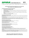
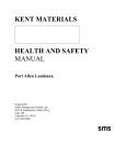
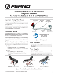
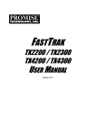
1
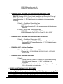
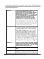
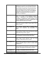
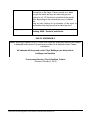
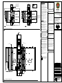
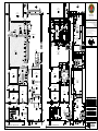
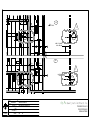
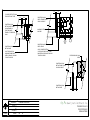
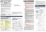
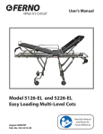
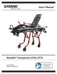
Richard Pajor CSCMP/C.P.P.
Procurement Specialist
City of Hamilton
Corporate Services Department
Procurement Section
Phone: (905) 546-2424, ext.: 4740
Fax:
(905) 546-2327
E-Mail: [email protected]
Date Issued: Friday, September 13, 2013
City of Hamilton
REQUEST FOR TENDERS
Contract Number: C13-55-13
Contract Title: Renovations and Reconfiguration of the
Hamilton Paramedic Services Station 30
ADDENDUM 5
The following queries and responses, issued by the Procurement Section shall form part of the
Request for Tenders documents for the above, and the revisions and additions noted herein
and any attachments shall read in conjunction with all other documents. This Addendum shall,
however, take precedence over all previously issued Request for Tenders documents where
differences occur.
Included in this Addendum: 7 pages for Addendum 5
1 page for Drawing A002.2
1 page for Drawing A004
1 page for Supplemental Drawing SDA-001
1 page for Supplemental Drawing SDA-002
1 page for Supplemental Drawing SDA-003
14 pages for Backboard Washer User’s Manual
26 pages in total
___________________________________________________________________________
1. DRAWINGS
1. DRAWING A002.2– Overall Plan
DELETE Drawing A002.2– Overall Plan, and
REPLACE with Drawing A002.2– Overall Plan issued September 11, 2013,
attached to this Addendum to incorporate the following:
.1 Detail 1 – Ground Floor Overall Plan
.1 ADD North Garage and South Garage labels
.2 Block Types
.1 ADD block type B6.
.3 Demolition Legend
.1 ADD General Demolition Note No.8.
C13-55-13 Addendum 5
Renovations and Reconfiguration of the Hamilton Paramedic Services Station 30
Page 1 of 7
.
2 REVISE demolition note D5.
.3 REMOVE demolition note D9.
2. DRAWING A004 – Ground Level Demolition and Renovation Plan
DELETE Drawing A004 – Ground Level Demolition and Renovation Plan and
REPLACE with Drawing A004 – Ground Level Demolition and Renovation Plan
issued September 11, 2013, attached to this Addendum to incorporate the
following:
.1 Detail 2 – Work Area 1 Demolition Plan
.1 REMOVE demolition note D9.
.2 ADD demolition note D5 to the current oxygen cylinder storage
millwork
.2 Detail 1 – Work Area 1 Renovation Plan
.1 REVISE section tag 5/A007 to 5/A008
.1
.2 REVISE elevation tag 3/A007 in Room 122-A to 4/A007
.2
.3
3. DRAWING A005 – Ground Level Demolition Plan and New RCP
.1 Detail 1 – Work Area 1 Renovation RCP
.1 Revise section tag 5/A007 to 5/A008 as per Supplemental
Drawing SDA-001 issued September 11, 2013 and attached to
this Addendum.
4. DRAWING A007 – Interior Elevations
.1 Detail 4 – Work Area 1 Renovation RCP
.1 Revise title to “STORAGE AND VENDING SPACE - INTERIOR
ELEVATIONS”
5. DRAWING A008 – Sections and Details
.1 Detail 5
.1 Revise detail tag Z/A008 to 1/A008 as per Supplemental Drawing
SDA-002 issued September 11, 2013, and attached to this
Addendum.
.2 ADD Detail 10 – Door Frame Profiles as per Supplemental Drawing
SDA -003 attached to this Addendum.
2. BIDDER QUESTIONS AND CITY RESPONSES
In responding to the following questions, the City of Hamilton has made every effort
to refer the Bidders to the most applicable section(s) of the Request for Tender,
where appropriate. However, in doing so, this does not relieve the Bidders of their
responsibility to read the entire Request for Tender and to satisfy themselves as to
C13-55-13 Addendum 5
Renovations and Reconfiguration of the Hamilton Paramedic Services Station 30
Page 2 of 7
whether there may also be other provisions in the Request for Tenders that are
responsive to their questions.
Question #1
Could you provide some information on the height of the
existing partitions (especially with respect to the
partitions we remove). Detail 5/A008 shows that at the
New Staff Room 115 is a 2 storey situation, is this
consistent for existing rooms 118, 115, 114,114A, 114B
and 102 (the rooms we work in on the west side of the
building) and do the existing partitions go to the
underside of the 2nd floor? At the New Ambulance
Storage Room 123 it is a single storey going the full
height of the 2 storeys, is this consistent for the existing
rooms 123, 110A,110B, 110, Vending Machine Storage
Closet and 110C,(the rooms we work in on the east side
of the building) and do the existing partitions go to the
u/s of the metal deck roof? Due to the varying heights, it
is important that we have this information.
City Response #1
1. Room 115 is not a 2-storey situation. Detail 5/A008
is a section showing the new corridor’s relationship
to existing conditions, which is further detailed in
Detail 1/A008. Existing rooms 118, 115, 114, 114A,
114B and 102 are all single storey. What might be
confused as a second storey is a false ceiling, as
called out in Detail 1/A008.Partitions were not
checked to see if they went to the underside of the
second floor. Existing Room 123 is a partitioned off
area of the vehicle storage garage; meaning, it has
no ceiling cap. This condition applies to Room 110
and 122-A. Rooms 110-A, 110-B, and 110-C have a
second storey above them. Please refer to Drawing
A005 which shows all existing and new ceilings.
Question #2
In room 118 – Existing Women’s Washroom – there are
existing ceramic wall tiles on the North, East and South
Partitions. Can you please clarify if the tiles on the
partitions that remain are to be removed?
City Response #2
Refer to Item 1.1 Drawing A002.2- Overall Plan
above.
Question #3
If they are to be removed, can you please provide some
clarification on what we include for the removals on the
North partition. I ask this because as you see from the
C13-55-13 Addendum 5
Renovations and Reconfiguration of the Hamilton Paramedic Services Station 30
Page 3 of 7
attached picture (pic 30137) you can tell they start at the
end of the lockers (the lockers go from the edge of the
door into room 117 Existing Exercise Room and
continue to just before the BF Washroom toilet partition)
but you can’t tell if they are also behind the lockers and
if so how far they go. I tried to determine this at the site
meeting but you could not tell.
City Response #3
All tiles are to be removed. We cannot confirm
whether they extend behind the lockers, but if they
do, they will have to be removed as well. Refer to
Item 1.1 Drawing - Overall Plan above.
Question #4
In room 123 – Existing Ambulance Storage – in the East
/ South corner, on the East wall there is an closet type
item with 2 sets of double doors (see attached picture
(pic 30088).There is a dotted line on the drawing but no
demolition note. Please clarify what we are doing with
this item.
City Response #4
Refer to Item 1.1 Drawing A002.2 - Overall Plan and
Item 1.2 Drawing A004 – Ground Level Demolition
and Renovation Plan above.
Question #5
The Demolition note D9 – ‘Existing bollard to be
removed…’ is indicated at the 2 bollards at the OH
Doors being removed on the north and south elevations
for a total of 4.However, on detail 1/A004 Renovation
Plan – there are still bollards indicated in all 4 of these
locations. Please clarify if we are to remove these
bollards?
City Response #5
Refer to Item 1.1 Drawing A002.2 - Overall Plan and
Item 1.2 Drawing A004 – Ground Level Demolition
and Renovation Plan above.
Question #6
In room 110-C at the east partition (which at present is a
block partition that only goes to approx. 8’ high – see
attached picture 30044) we enlarge the door opening
and infill with a B6 partition. There is no B6 partition
indicated on A002.2, please clarify what this partition is.
City Response #6
Refer to Item 1.1 Drawing A002.2 - Overall Plan
above.
Question #7
In room 123 – New Ambulance Storage – There is an
item against the east partition with the notation ‘Existing
C13-55-13 Addendum 5
Renovations and Reconfiguration of the Hamilton Paramedic Services Station 30
Page 4 of 7
backboard washer to be moved from north garage,
installed and connected to new plumbing? During the
site meeting we did not go into any other areas and so
were not able to view this item. Could a picture of this
item be included and some information on what it is
such as size, weight etc. Also, is the north garage the
building titled ‘Existing Metal Building’ on the A002.1
drawing? If not please provide some information on
where the north garage is.
City Response #7
Refer to Item 1.1 Drawing A002.2 - Overall Plan
above. A cut sheet of the backboard washer is
included inincluded in this Addendum. General
Contractor to confirm the current location of the
piece of equipment at the time of construction and
notify the Architect prior to relocation.
Question #8
There are 2 locations for the section detail 5/A007. I
believe this should be 5/A008. Please clarify if this is
correct.?.correct?
City Response #8
That is correct. Refer to Item 1.2 Drawing A004 –
Ground Level Demolition and Renovation Plan
above.
Question #9
In room 122-A – Storage and Vending Space there is an
elevation reference 3/A007.I believe this should be 4/A007.
Please clarify if this is correct.?.correct?
City Response #9
That is correct. Refer to 1.2 Drawing A004 – Ground
Level Demolition and Renovation Plan above.
Question #10
These elevations reference east and west elevations. I
believe these should reference north and south
elevations. Please clarify if this is correct?
City Response #10
This reference is based on the true east and west.
Refer to elevation tags on plans if unsure which
elevation it is.
Question #11
These details all indicate a stainless steel finish on them.
Please provide some information on the stainless steel,
what type, what gauge and what finish you require.
City Response #11
16 Gauge 304 Brushed Stainless Steel Sheet.
Question #12
You indicate a pier and footing below the Gate Control
C13-55-13 Addendum 5
Renovations and Reconfiguration of the Hamilton Paramedic Services Station 30
Page 5 of 7
Cabinet and it tells us to refer to the structural drawing. I
do not see any information on the structural drawings
with regards to these piers and footings. Please provide
a detail on these.
City Response #12
Refer to Details 1 and 2 on Drawing S1.1.
Question #13
At the Partial Plan at the new Coiling Door you indicate
HHS columns at the jambs of the new door opening and
a ‘C200 at the head. On the A008 drawing, detail 6 – it
indicates a ‘C’ Channel at the door jamb. Please clarify if
we are to include for HHS Columns or ‘C’ Channels at
the new door jambs?
City Response #13
Drawing A008 Detail 2 and Drawing A008 Detail 6,
which show jamb details, state that you should refer
to structural drawings for the O.H. Door metal frame.
Refer to Drawing S-1A for all structure on the jambs.
Question #14
The one question there still seems to be some confusion
about which I haven’t asked already is at the east
corridor wall in the area of the new office. Above and
below this area we are creating a false ceiling as per
detail 5/A007 and it has a 2 hour fire rating. In this one
small section however, it tells us to ‘extend the existing
drywall partition, type P1(P1 (which is only 1 hour fire
rated) to u/s of existing concrete slab)’. So there are a
couple of issues that we are confused about–If the
sections of this partition to the north and south are a 2
hour fire rated partition, why is this area only a 1 hour
fire rated partition? Detail 5/A007 seems to show that
the concrete slab creating the second floor stops at the
west side of this corridor so how do we extend the wall
on the east side of the corridor to the u/s of the concrete
slab? Wouldn’t the partition in this area need to be
extended to the u/s of the steel deck (approximately 22
ft AFF) and if so why wouldn’t we just put the same false
ceiling at this location as we do to the north and south of
it??
City Response #14
Refer to Drawing A003 for fire ratings. Detail 5 of
Drawing A008 is a section cut through the corridor
at that particular portion where there is no second
storey above, and the corridor needs a rated
horizontal separation above it. The floor slab of the
second floor is existing above existing rooms 110,
110-A, and 110-B.
C13-55-13 Addendum 5
Renovations and Reconfiguration of the Hamilton Paramedic Services Station 30
Page 6 of 7
Question #15
The hollow metal contractors would like some additional
information on the frame. There currently is no detail
through the frame and they are assuming you are
looking for a 5 1/2” throat but I would think that would
differ depending on the material the door is installed
into.
They are also looking for an elevation of the doors or
confirmation that they are all just a slab style door?
City Response #15
They are all just slab style doors. Refer to Item 1.5
Drawing A008 – Sections and Details.
END OF ADDENDUM 5.
Bidders providing a signed Form of Tender have made any necessary inquiries with respect
to addenda issued by the City and have provided for all addenda in their Tender
submission.
All addenda will be posted on the City’s Biddingo.com bid portal at:
biddingo.com/hamilton
Procurement Section, City of Hamilton, Ontario
(Revised: February 5, 2013)
C13-55-13 Addendum 5
Renovations and Reconfiguration of the Hamilton Paramedic Services Station 30
Page 7 of 7
DEMOLITION LEGEND
BLOCK TYPES:
GENERAL DEMOLITION NOTES:
1.
PHASING LEGEND:
WORK IN THIS AREA TO BE COMPLETED
IN A TIMELY MANNER WITH MINIMAL
DISTURBANCE TO THE TENANT.
MAINTAIN ACCESS TO EXIT AT ALL
TIMES. IF EXITING HAS TO BE BLOCKED,
NOTIFY THE CITY'S INSPECTOR AND
PROCEED UPON APPROVAL.
HOARDING LINE
2.
B1
90mm CONCRETE BLOCK
PATCH AND REPAIR ALL ADJACENT SURFACES TO AREAS OF
DEMOLITION AS REQUIRED TO MATCH EXISTING OR READY
FOR NEW FINISH.
B2
140mm CONCRETE BLOCK
CLEAN, PATCH, AND REPAIR ALL SURFACES TO REMAIN AS
REQUIRED FOR NEW FINISHES.
B3
190mm CONCRETE BLOCK
B4
240mm CONCRETE BLOCK
B5
290mm CONCRETE BLOCK
B6
MATCH EXISTING ADJACENT CONCRETE BLOCK
AREA OF WORK
3.
4.
5.
6.
WORK IN THIS AREA TO BE COMPLETED
IN A TIMELY MANNER WITH MINIMAL
DISTURBANCE TO THE TENANT.
MAINTAIN ACCESS TO EXIT AT ALL
TIMES. IF EXITING HAS TO BE BLOCKED,
NOTIFY THE CITY'S INSPECTOR AND
PROCEED UPON APPROVAL.
GC TO COORDINATE EXTENT OF DEMOLITION WITH
MECHANICAL, ELECTRICAL, AND STRUCTURAL DRAWINGS.
ANY AREA NOT SHOWN ARCHITECTURAL WHICH REQUIRES
INSTALLATION OF NEW SERVICES IS TO BE RETURNED TO
ORIGINAL STATE TO MATCH EXISTING.
REVIEW HARDWARE SCHEDULE FOR ALL EXISTING DOORS
TO REMAIN, DEMOLISH ANY AND ALL HARDWARE AS
REQUIRED FOR INSTALLATION OF NEW DOOR HARDWARE.
PROVIDE TEMPORARY SUPPORT FOR ADJACENT CEILING,
LIGHT FIXTURES, DIFFUSERS, CEILING MOUNTED DEVICES,
ETC., AS REQUIRED FOR AREAS WHERE CEILINGS ARE
REQUIRED TO BE REMOVED TO INSTALL NEW OR MODIFY
EXISTING SERVICES. ALL CEILINGS TO BE RESTORE BACK
TO ORIGINAL STATE.
ALL EXISTING FURNITURE IN THE LUNCH ROOM TO BE
REMOVED AND REUSED. GC TO STORE AND PROTECT
DURING CONSTRUCTION UNTIL READY FOR
RE-INSTALLATION.
F1
16mm GYPSUM WALLBOARD ON 13mm RESILIENT
CHANNELS
F2
16mm GYPSUM WALL BOARD ON 22mm FURRING
CHANNELS
ALL OTHER EXISTING FURNITURE TO BE SALVAGED AND
TURNED OVER TO OWNER.
F3
16mm GYPSUM WALL BOARD ON 41mm STEEL STUD
FRAMING
8.
ALL EXISTING WALL FINISHES TO BE REMOVED WHERE NEW
FINISHES ARE TO BE APPLIED. ALL SURFACES TO BE
PREPARED FOR NEW FINISHES.
F4
16mm GYPSUM WALLBOARD ON 64mm STEEL STUD
FRAMING
F5
16mm GYPSUM WALL BOARD ON 92mm STEEL STUD
FRAMING
F6
16mm GYPSUM WALL BOARD ON 152mm STEEL STUD
FRAMING
DEMOLITION NOTES:
D2
PHASE 1
PHASE 2
D3
1
-
CONSTRUCTION PHASING PLANS
D4
SCALE: 1:300
WORK AREA 1
REFER TO DRAWINGS A004, A005
PARTITION TYPES:
EXISTING APPLIANCE TO BE REMOVED AND REUSED. GC
TO STORE AND PROTECT DURING CONSTRUCTION UNTIL
READY FOR RE-INSTALLATION. REFER TO AND
COORDINATE WITH FLOOR PLANS.
EXISTING SINK TO BE REMOVED. PATCH AND REPAIR
ADJACENT SURFACES AS REQUIRED TO MATCH EXISTING
AND MAKE READY FOR NEW FINISH. REFER TO AND
COORDINATE WITH FLOOR PLANS.
EXSTING WATER CLOSET/SHOWER TO BE REMOVED.
SERVICES TO BE REMOVED BACK TO SOURCE AND
CAPPED AS REQUIRED. PATCH AND REPAIR ADJACENT
SURFACES AS REQUIRED TO MATCH EXISTING.
D5
EXISTING MILLWORK TO BE DEMOLISHED. PATCH AND
REPAIR ADJACENT SURFACES AS REQUIRED FOR NEW
CONSTRUCTION.
D6
EXISTING LOCKERS TO BE REMOVED AND TURNED OVER
TO OWNER.
D7
EXISTING NARCOTICS CABINET TO BE REMOVED AND
REUSED. GC TO STORE AND PROTECT DURING
CONSTRUCTION UNTIL READY FOR RE-INSTALLATION.
D8
EXISTING DOOR/METAL SIDING & INSULATION TO BE
REMOVED. REFER TO AND COORDINATE WITH
DEMOLITION FLOOR PLAN.
D9
WORK AREA 2
REFER TO NOTES ON A002
REMOVE EXISTING WALL INCLUDING ALL SERVICES AS
INDICATED. SERVICES TO BE REMOVED BACK TO SOURCE
AND CAPPED AS REQUIRED. PATCH AND REPAIR
ADJACENT SURFACES AS REQUIRED TO MATCH EXISTING
OR MAKE READY FOR NEW FINISHES.
P1
16mm GYPSUM WALLBOARD ON ON 92mm STEEL STUD
FRAMING. SITE VERIFY AND MATCH EXISTING ADJACENT
WALL TYPE.
P2
REFER TO ULC. DESIGN NO.453 FOR 2-HR FIRE RATING
ASSEMBLY. 2 LAYERS OF 16mm GYPSUM WALL BOARD ON
64 mm STEEL STUD FRAMING WITH BATT INSULATION.
P3
REFER TO ULC. DESIGN NO.452 SYSTEM-E FOR 2-HR
NONBEARING ASSEMBLY RATING. INCLUDE BATT
INSULATION.
P4
16mm GYPSUM WALL BOARD ON 152mm STEEL STUD
FRAMING WITH ACOUSTIC INSULATION BLANKETS IN STUD
CAVITIES.
Contractor must verify all dimensions on the job and report any
discrepancy to architects before proceeding with the work.
All drawings and specifications are the property of the architect and must
be returned at the completion of the work.
This drawing is not to be used for construction until
countersigned.
Date:
Seals
NEW EXTERIOR WALL TO MATCH EXISTING. METAL SIDING
W1 TO MATCH EXISTING WITH 4" VINYL FACED FIBREGLASS,
METAL BUILDING INSULATION INSTALLED BETWEEN NEW
METAL GIRTS CONNCTED TO AND MATCHING EXISTING.
PAINT NEW GIRTS AND NEW INTERIOR LINER WITH
ELECTROSTATIC COATING.
GENERAL NOTES:
NOT IN USE
1.
NOT ALL BLOCK & FURRING TYPES SHOWN MAY BE USED,
REFER TO FLOOR PLANS FOR TYPES IN THE PROJECT.
EXISTING EXIT SIGN TO BE REMOVED AND REUSED.
REFER TO AND COORDINATE WITH ELECTRICAL
DRAWINGS.
2.
ALL BLOCK PARTITIONS TO EXTEND TO U/S OF STRUCTURE
UNLESS OTHERWISE NOTED. PROVIDED LATERAL BRACING
AS REQUIRED.
D11
EXISTING CEILING TO BE REMOVED. SERVICES TO BE
REMOVED BACK TO SOURCE AND CAPPED AS REQUIRED
AND MAKE READY FOR NEW CEILING.
3.
GC TO SITE VERIFY BLOCK TYPES DENOTED WITH A ' * ' AND
MATCH TO EXISTING.
4.
USE 75% SOLID OR GREATER OR LIGHT WEIGHT CONCRETE
BLOCKS AS REQUIRED TO ACHIEVE FIRE SEPARATIONS
NOTED, COORDINATE W/ FIRE & LIFE SAFETY DRAWINGS.
ENSURE FIRE SEPARATIONS ARE SEALED AT ALL
PENETRATIONS AND TO STRUCTURE W/ FIRE STOP.
5.
FURRING TO EXTEND TO 150mm ABOVE FINISHED CEILING
OR TO U/S OF STRUCTURE WHERE NO CEILING EXIST
(REFER TO REFLECTED CEILING PLANS) UNLESS
OTHERWISE NOTED.
D13
Drawings are not to be scaled.
WALL TYPES:
D10
D12
489 VICTORIA AVE NORTH,
HAMILTON, ON, L8L 5H1, CANADA
FURRING TYPES:
7.
D1
FIRE STATION 30
RENOVATIONS
REMOVE EXISTING WALL BETWEEN TWO ROOMS UP TO A
HEIGHT THAT MATCHES THE EXISTING LOWER ACT LEVEL.
REMOVE ALL SERVICES AS INDICATED. SERVICES TO BE
REMOVED BACK TO SOURCE AND CAPPED AS REQUIRED.
PATCH AND REPAIR ADJACENT SURFACES AS REQUIRED
TO MATCH EXISTING OR MAKE READY FOR NEW FINISHES.
PROTECT EXISTING ACT AND REPAIR IF DAMAGED.
REMOVE EXISTING GYPSUM BOARD ON BOTH ENDS OF
THE STUD. KEEP THE STUD IN PLACE FOR INSTALLATION
OF NEW GYPSUM BOARD FOR FIRE RATING. REFER TO
PLAN FOR NEW PARTITION TYPE.
D14
EXISTING ACT CONTINUES ABOVE DEMOLISHED
PARTITION. REPAIR OR REPLACE EXISTING ACT TILE IF
DAMAGED.
D15
EXISTING CATCH BASIN TO BE REMOVED. REFER TO
MECH. DRAWINGS.
WORK AREA 2
GENERAL NOTES:
D16
EXISTING MILLWORK TO BE REMOVED AND REUSED. GC
TO STORE AND PROTECT DURING CONSTRUCTION UNTIL
READY FOR RE-INSTALLATION.
1.
2.
3.
PAINT ALL SIDING SURFACES TO MATCH EXISTING.
REFER TO MECHANICAL DRAWING FOR SCOPE OF
MECHANICAL WORK.
REFER TO ELECTRICAL DRAWINGS FOR SCOPE OF
ELECTRICAL WORK.
LEGEND:
DENOTES EXTENT OF EXISTING FLOOR FINISH TO
TO BE REMOVED. EXISTING SLAB TO BE PATCHED
AND REPAIRED AS REQUIRED AND MADE READY
FOR NEW FINISH. PATCH AND REPAIR ADJACENT
SURFACES AS REQUIRED TO MATCH EXISTING.
SOUTH GARAGE
NORTH GARAGE
04
FOR ADDENDUM NO. 4
2013-09-11
FOR ADDENDUM NO. 3
2013-09-05
03
ISSUED FOR TENDER
2013-05-07
02
ISSUED FOR CLIENT REVIEW 2013-02-14
01
ISSUED FOR PRICING
No.
Issues/Revisions
2012-10-19
Date
Drawing Title:
OVERALL PLAN
Issue Date:
Drawn by:
Project No.:
2013-09-11
PM
Checked by:
11103-07
Scale:
AS SHOWN
-
GROUND FLOOR OVERALL PLAN
SCALE: 1:150
E
TRU TH
R
NO
PROJECT
NORTH
Drawing No.:
1
DP
A002.2
3
1
A006
A006
STAIR#2
120
EXISTING
EXERCISE ROOM
STAIR#2
D8
285
117
D8
120
1630
6/A008
7/A008
EXISTING
EXERCISE ROOM
2050
1570
P3
FIRE STATION 30
RENOVATIONS
W1
P3
360
EX
489 VICTORIA AVE NORTH,
HAMILTON, ON, L8L 5H1, CANADA
2510
2685
W1
2/A008
8285
1500
8/A008
3/A008
117
4/A008
460
123-02
RELOCATED WASHING
MACHINES
D2
A007
B
A007
900
118
B3
2695
3
A007
920
B3
B3
D3
PCT
D2
PCT3
This drawing is not to be used for construction until
countersigned.
Date:
RELOCATED SINK
& EYEWASH STATION
PCT3
P2
B4
VCT
118-01
D6
All drawings and specifications are the property of the architect and must
be returned at the completion of the work.
Seals
EXISTING BACKBOARD
WASHER TO BE MOVED
FROM NORTH GARAGE,
INSTALLED, & CONNECTED
TO NEW PLUMBING
123-01
MW-02
EX
MW-01
B2
EX
ALIGN
F2
A
D2
EX
D
5
A007
EXISTING RELOCATED
KITCHEN APPLIANCES
5
A008
B
EX
123-03
5
2740
123
Contractor must verify all dimensions on the job and report any
discrepancy to architects before proceeding with the work.
B
NEW WOMEN'S WRM
& CHANGING RMS
1525
D2
A008
EX
D15
C
D2
4330
EXISTING
STAFF ROOM
B3
C
D3
D5
Drawings are not to be scaled.
A
ALIGN
EXISTING
AMBULANCE STORAGE
D1
2730
H
B6
D4
A007
G
123
9235
D3
D1
D1
6
D
6
I
F
4410
D3
1195
D5
D3
A
ALIGN
A007
6
1000
E
NEW AMBULANCE
STORAGE
B4
ALIGN
6
118
B4
MW-03
B3
ALIGN
EXISTING
WOMEN'S WRM
B3
1500
ALIGN
D2
1/A008
700
PCT
D3
EX
B3
MW-05
NEW STAFF ROOM
115
115
D2
MW-06
P2
STORAGE AND
VENDING SPACE
A
D1
EQ.
D1
D5
EQ.
1395
D16
EX
VCT
D9
ALIGN
MW-EX
800
D1
D7
110-A
115-A
113
D1
ALL WORK STATIONS
& OFFICE CHAIRS (N.I.C.)
EXISTING
RELAXING ROOM
EXISTING
RELAXING ROOM
114-A
114-B
610
D7
SITE VERIFY
SITE VERIFY
D7
610
610
D1
D12
EXISTING
STORAGE AND OFFICE
EXISTING
ELECTRICAL ROOM
110-B
EXISTING
STORAGE
112
EXISTING
ELECTRICAL ROOM
ALIGN
D1
P2
NEW WORK AREA
EXISTING
OFFICE
EXISTING DRYWALL TO BE EXTENDED
WITH PARTITION TYPE P1 TO U.S. OF
EXISTING CONCRETE SLAB AND SEALED
D7
113
B
122A-02
C
EXISTING
STORAGE AND OFFICE
EXISTING
OFFICE
2
A007
RELOCATED
NARCOTICS CABINETS
C
EX
ALIGN
D
114
SITE VERIFY
SITE VERIFY
D1
EX
122A-01
115-01
A
MW-04
EXISTING
VESTIBULE
B
A007
P4
800
ALIGN
P4
122-A
4
EX
3200
D1
P1
NEW OFFICE
110-A
P1
112
110
EX
EXISTING
OFFICE
EXISTING
OFFICE
D2
109
VCT
110A-01
109
D13
111
EXISTING
OFFICE
NEW CORRIDOR
111
122
05
ALIGN
D1
P2
D2
D2
D1
EXISTING
HALL
D1
106
EX
110
110-02
A
EX
1
106
102
110-C
D1
04
FOR ADDENDUM NO. 1
2013-08-28
03
ISSUED FOR TENDER
2013-05-07
02
ISSUED FOR CLIENT REVIEW 2013-02-14
01
ISSUED FOR PRICING
No.
Issues/Revisions
B6
D12
STAIR#1
ENTRANCE
5
A008
A008
105
101
SIM.
5
W1
SIM.
8/A008
Issue Date:
Drawn by:
-
WORK AREA 1 DEMOLITION PLAN
SCALE: 1:50
1
-
WORK AREA 1 RENOVATION PLAN
SCALE: 1:50
4
8/A008
Project No.:
PM
Checked by:
11103-07
Scale:
Drawing No.:
A006
E
TRU TH
R
NO
PROJECT
NORTH
A006
3/A008
7/A008
D8
2013-09-11
DP
SIM.
SIM.
2
Date
GROUND LEVEL
DEMOLITION AND
RENOVATION PLAN
3000
SIM.
2
2012-10-19
Drawing Title:
1/A008
101
105
2013-09-03
P2
NEW
ENTARNCE LOBBY
STAIR#1
FOR ADDENDUM NO. 2
B
A007
2540
EXISTING
FOYER
EXISTING
STORAGE
2013-09-11
NEW STORAGE
P2
110-01
EXISTING
HALL
FOR ADDENDUM NO. 4
640
EXISTING
OFFICE
A004
1:50
EQ.
EQ.
EQ.
123
EQ.
3660
EQ.
EX.
EX.STRUC.
E
5
A008
A008
LINE OF LOWER
WALL BELOW
EQ.
EQ.
5
110
102
EQ.
EQ.
EQ.
LINE OF LOWER
WALL BELOW
9/A008
SIM.
EQ.
5
A008
EQ.
A008
SIM.
5
101
Sheet No:
SDA-001
Title:
Issued for:
Add. No. 4
WORK AREA 1
RENOVATION RCP
Scale:
PROJECT
NORTH
TRUE H
NORT
1:50
Date:
2013-09-11
No.:
11103-07
Ref:
By:
1/A005
Chk:
PM
DP
TENDER C13-55-13
FIRE STATION 30
RENOVATIONS
EXISTING
OFFICE
NEW AMBULANCE
STORAGE
NEW STAFF ROOM
NEW CORRIDOR
115
122
Sheet No:
SDA-002
Title:
123
3200
1/A008
VARIES
113
SECTION
Issued for:
Add. No. 4
TENDER C13-55-13
FIRE STATION 30
RENOVATIONS
Scale:
PROJECT
NORTH
TRUE H
NORT
1:50
Date:
2013-09-11
No.:
11103-07
Ref:
By:
5/A008
Chk:
PM
DP
16
P1 OR P2. REFER TO PLAN
FOR PARTITION TYPES
16
50
PAINTED HOLLOW
METAL DOOR FRAME,
ALIGN FRAME W/
EXISTING DOOR
FRAME AT CORRIDOR
WALL
51
PAINTED HOLLOW
METAL FRAME FILLED
SOLID W/ GROUT
MASONRY STRAP
ANCHOR
F2
B2
PAINTED HOLLOW
METAL DOOR
PAINTED HOLLOW
METAL DOOR
CONT. GWB EDGE TRIM
W/ SEALANT AND CONT. FOAM
BACKER ROD, SEALANT COLOUR
TO MATCH DOOR
CONT. SEALANT ALL
AROUND FRAME BOTH
SIDES, SEALANT COLOUR
TO MATCH DOOR
EXISTING BLOCK WALL
OR B6
PAINTED HOLLOW
METAL FRAME FILLED
SOLID W/ GROUT
PAINTED HOLLOW
METAL DOOR
Sheet No:
SDA-003
Title:
16
50
FRAME PROFILES
Issued for:
Add. No. 4
TENDER C13-55-13
FIRE STATION 30
RENOVATIONS
Scale:
PROJECT
NORTH
TRUE H
NORT
1:5
Date:
2013-09-13
No.:
11103-07
Ref:
By:
10/A008
Chk:
PM
DP
Users' Manual
Bio-Board Technologies by Ferno
Backboard Washer
April 2003 GLO
Pub. No. 234-3243-00
Disclaimer
This manual contains general instructions for the use, operation
and care of this product. The instructions are not all-inclusive.
Safe and proper use of this product is solely at the discretion of
the user. Safety information is included as a service to the user. All
other safety measures taken by the user should be within and under
consideration of applicable regulations. It is recommended that
training on the proper use of this product be provided before using
this product in an actual situation.
Retain this manual for future reference. Include it with the product in
the event of transfer to new users. Additional free copies are available
upon request from Customer Relations.
Proprietary Notice
The information disclosed in this manual is the property of FemoWashington, Inc., Wilmington, Ohio, USA. Ferno-Washington, Inc.
reserves all patent rights, proprietary design rights, manufacturing
rights, reproduction use rights, and sales use rights thereto, and to any
article disclosed therein except to the extent those rights are expressly
granted to others or where not applicable to vendor proprietary parts.
© Copyright Ferno-Washington, Inc. All Rights Reserved.
Ferno-Washington, Inc.
70 Weil Way
Wilmington, OH 45177-9371
U.S.A.
Telephone (U.S.A. and Canada). 1.800.733.3766
Telephone (Worldwide) .................. + 1.937.382.1451
Fax (United States) ............................ 1.937.382.1191
Fax (Outside U.S.A.) ..................... + 1.937.382.6569
Internet ............................................ www.ferno.com
2
.......
:
.......
-. -ÿ -
....................
-
.......
© Ferno-Washington, Inc. 234-3243-00 April 2003
TABLE OF CONTENTS
Section
Page
Section
Page
1 - Safety Information ...................................................... 4
4.3 Disinfectant Flowmeter .................................... 8
1.1 Danger ................................................................. 4
4.4 Disinfectant Reservoir ...................................... 9
1.2 Warning ............................................................... 4
5 - Using the Backboard Washer ........................... 10, 11
1.3 Important ............................................................. 4
5.1 Before Placing the Backboard Washer in
1.4 Safety and Instruction Labels ............................. 4
• 1.5 Bloodborne Disease Notice ................................ 4
Service ............................................................ 10
5.2 General Guidelines forUse ............................. l0
2 -About the Backboard Washer ................................ 5, 6
5.3 Operating the Backboard Washer .................. 11
2.1 Backboard Washer Description .......................... 5
6 - Maintaining the Backboard Washer ...................... 12
2.2 General Specifications ......................................... 5
6.1 Maintenance Schedule ................................... 12
2.3 Components ........................................................ 6
6.2 Cleaning the Backboard Washer .................... 12
3 - Installing the Backboard Washer .............................. 7
6.3 Polishing the BackboarclWasher .................. 12
3.1 Site Setup ............................................................ 7
3.2 Attaching the Adjustable Feet ............................ 7
4- Using the Features .................................................... 8, 9
4.1 Control Panel ....................................................... 8
6.4 Inspecting the Backboard Washer ................. 12
7 -Limited Warranty .................................................... 13
8 - Ferno Customer Relations ...................................... 13
Training Record ............................................................ 14
4.2 Emergency Stop Button .................... : ................. 8
Illustrations
Components ................................................................................. 6
Figure 1- Control Panel ............................................................ 8
Figure 2 - Emergency Stop Button ........................................... 8
Figure 5 - Pushing a Backboard into
the Entrance Portal .......................................... 11
Figure 6 - Pulling a Backboard from the Exit
Figure 3 - DisinfectantFlowmeter. ............................................ 8
Portal .................................................................... 11
Figure 4- Disinfectant Reservoir. ........................................... 9
Maintenance Table ................................................................ 12
Serial Number Location ......................................................... 13
© Ferno-Washington, Inc. 234-3243-00 April 2003 ..... . ........................................... ....................... .............. : ,
3
1 - SAFETY INFORMATION
1.1 Danger
1.3 Important
The following danger alert appears in this manual.
Boxes like the one below emphasize important
information.
Important
Electric shock can cause death or serious
injury. Install, use, operate, and maintain
the backboard washer only as described
in this manual.
If the yellow Disinfectant Low light is lit, the
disinfectant reservoir is empty and the
backboard washer will not operate. Refill the
reservoir before restarting the backboard
washer.
1.2 Warning
The following warnings appear in this manual.
1.4 Safety and Instruction Labels
Safety and instruction labels place important information
on the backboard washer.
Improper use of the backboard washer can
cause injury. Use the backboard washer
only for the purpose described in this
manual.
Improper operation can cause injury.
Operate the backboard washer only as
described in this manual.
Reaching into the entrance or exit portals
can cause injury. Keep hands outside the
backboard washer.
Read and follow label instructions. Replace worn or
damaged labels immediately. New labels are available
from Customer Relations or from your Ferno distributor
(page 13).
1.5 Bioodborne Disease Notice
To reduce the risk of exposure to bloodbome diseases
such as HIV-I and Hepatitis, wear disposable
examination gloves when operating the backboard
washer.
Improper maintenance can cause injury.
Maintain the backboard washer only as
described in this manual.
Modifying the backboard washer can cause
injury and damage. Use the backboard
washer only as designed by Ferno.
Improper parts and service can cause injury.
Use only Ferno parts and Ferno-approved
service on the backboard washer.
4 ........................................... - ......... -= ............... © Ferno-Washington, Inc. 234-3243-00 April 2003
2 - ABOUT THE BACKBOARD WASHER
2.1 Backboard Washer Description
The Bio-Board Technologies by Ferno Backboard
Washer (referred to in this manual as the backboard
washer) is designed to quickly disinfect and clean
backboards. It can accommodate all standard
backboards, as well as Ferno's EXL Scoop. The
backboard washer is for professional use only.
Improper use of the backboard washer can
cause injury. Use the backboard washer
only for the purpose described in this
manual.
The backboard washer is a stationary, sealed stainless
steel unit with internal jets that dispense disinfectant
and a constant stream of hot water. Rotating internal
brushes clean backboards as they are fed through the
backboard washer one at a time.
The backboard washer can be installed indoors, or
outdoors inside an appropriate shelter.
The backboard washer is for use with backboards at
least 60 inches in length and a maximum of 20 inches
wide.
2.2 General Specifications
Overall Height .................................. 47 in (119 cm)
From floor to bottom of backboard washer. ....... 22 in (56 cm)
Length ................................................ 50 in (127 cm)
Width .................................................. 37 in (94 cm)
Weight ............................................. 401 lb (182 kg)
Entrance/Exit Portals ................ 3-1/4 in x 20-3/8 in
(8.3 x 51.8 cm)
Disinfectant Capacity .............................. 9 gal (34 ltr)
Drain Size ........................................... :,..2 in (5 cm)
Volts ....................................................... 120 V AC
Amps .................................................................. 20
Hz ...................................................................... 60
Backboard minimum length ............... 60 in (152 cm)
Backboard maximum width ................. 20 in (51 cm)
Backboard maximum depth .................. 3 in (8 cm)
General specifications are rounded to the nearest whole
number. Metric conversions are calculated before rounding
the English measurements. For more information, contact
Femo Customer Relations (page 13) or your Femo distributor.
Ferno reserves the right to change specifications without
notice.
© Ferno-Washington, Inc, 234-3243-00 April 2003
: ............... " ........ = ........ ,, ÿ ÿ',-- ....... ÿ-=ÿÿ--- - .......... ÿ ........ ÿ-,=
5
2.3 Components
Emergency Stop
Button
Disinfectant Fill Cap
Start
Button
Stop
Button
Disinfectant
Flowmeter
Disinfectant
Low Light
Entrance Portal
USERS' MANUAL
Not Shown:
Exit Portal, Side Vents
For additional free
Users' Manuals, you
can contact Ferno
Customer Relations at
1.800.733.3766, or
www.ferno.com.
6 ............ -,, ................ - ÿ- ...... -----,- .... -: . .- ........................ - ...... © Ferno-Washington, Inc. 234-3243-00 April 2003
3 - INSTALLING THE BACKBOARD WASHER
3.1 Site Setup
The backboard washer can be installed indoors or
outdoors. If it is installed outdoors, it must be installed
inside a shelter where it is not exposed to harsh elements
or freezing temperatures.
Both sides of the backboard washer must be positioned
at least two feet away from the walls of the room or
shelter in which it is installed.The backboard washer
can be bolted to the floor (hardware not supplied) or
fitted with four adjustable feet that are shipped with the
unit. Whether installed indoors or outdoors, the backboard
washer must be kept level to operate properly.
Electric shock can cause death or serious
injury. Install, use, operate, and maintain
the backboard washer only as described
in this manual.
Prepare the installation site to local code. The backboard
washer must be hardwired by a qualified electrician to
a 120 V AC junction box with disconnect capability so
the power can be turned off if the machine requires
service. Refer to the wiring schematic shipped with the
backboard washer.
All plumbing must meet the National Plumbing Code, at
minimum. Check with your local government for
additional local codes affecting your area.
Have a qualified plumber install a 3/4-inch diameter hard
or flex hot water line hookup from the water supply to
the backboard washer. A 3/4-inch diameter NPT
(National Pipe Thread) female fitting is factory-installed.
If a backflow preventer is required by code, contact
Ferno Customer Relations, page 13.
The factory-installed drain hookup must be connected
to a 2-inch schedule 40 PVC drain pipe. Refer to the
plumbing schematic shipped with the backboard washer.
3.2 Attaching the Adjustable Feet
The backboard washer is shipped with four adjustable
feet that can be attached to keep it level. The backboard
washer must be level to operate properly.
To install the adjustable feet, unpack them and screw
them into the threaded holes in the base of the legs.
Use an adjustable wrench to adjust each foot until the
backboard washer is level.
© Ferno-Washington, Inc. 234-3243-00 April 2003
"-+ ................ = ..................... - ............ -:- ..................... ÿ
7
4 - USING THE FEATURES
4.1 Control Panel
erating Instructions
The control panel (Figure 1) is on the entrance end
of the backboard washer. It contains a green START
button, a red STOP button and a yellow
DISINFECTANT LOW light.
Stop Button
For instructions on using the STOP and START buttons,
see Operating the Backbocird Washer, page 11.
Disinfectant Low
Light
The DISINFECTANT LOW light comes on when
the disinfectant reservoir is empty. The backboard
washer will not start if the DISINFECTANT LOW
Electrical Hazard
Label
light is on.
Figure 1 - Control Panel
4.2 Emergency Stop Button
The EMERGENCY STOP button is located on top of
the backboard washer near the exit end (Figure 2).
Note: The STOP button on the entrance end of
the backboard washer also can be used as an
emergency stop.
To restart after stopping the backboard washer with
either the EMERGENCY STOP or STOP button:
1. Twist the EMERGENCY STOP or STOP button
to the right until it pops out.
2. Push the START button at the entrance end of
the machine.
4.3 Disinfectant Flowmeter
Figure 2 - Emergency Stop Button
The disinfectant flowmeter (Figure 3) increases or
decreases the number of ounces of disinfectant per
gallon of water mixed and sprayed on a backboard.
Follow the disinfectant manufacturer's directions for
use. The flowmeter should be set by authorized
personnel to produce the disinfectant manufacturer's
recommended mixture of disinfectant and water.
Turn the flowmeter knob clockwise to reduce the
flow of disinfectant. Turn the knob counterclockwise
to increase the flow.
Figure 3 - Disinfectant Flowmeter
8
.....................
.........
-
...................
© Ferno-Washington, Inc. 234-3243-00 April 2003
4.4 Disinfectant Reservoir
The disinfectant reservoir holds nine gallons of
disinfectant, which is sprayed on the backboard as it
passes through the backboard washer.
If the yellow DISINFECTANT LOW light (Figure 1,
page 8) is lit, the disinfectant reservoir is empty. This
will cause the backboard washer to stop. It cannot be
restarted until the reservoir is filled.
To fill the reservoir:
1. Unscrew the disinfectant fill cap on top of the
backboard washer.
2. Fill the reservoir with a disinfectant approved by
your local city, county, or state government for
disposal in sanitary drains (Figure 4).
3. Replace the cap.
Figure 4 - Filling the Disinfectant Reservoir
Important
If the yellow Disinfectant Low light is lit, the
disinfectant reservoir is empty and the
backboard washer will not operate. Refill the
reservoir before restarting the backboard
washer.
© Ferno-Washington, Inc. 234-3243-00 April 2003 .......... -:ÿ-- ............ --=: --= ........ ÿ .:ÿ-::-ÿ--ÿ-ÿ-ÿ--- .......... - .............. 9
5 - USING THE BACKBOARD WASHER
5.1 Before Placing the Backboard
Washer in Service
[] Personnel who will work with the backboard
washer need to read this manual.
[]
Install the backboard washer, following
instructions in Installing the Backboard Washer,
Electric shock can cause death or serious
injury. Install, use, operate, and maintain
the backboard washer only as described
in this manual.
page 7.
Follow the instructions in Inspecting the
Backboard Washer, page 12, to confirm that the
backboard washer operates properly.
5.2 General Guidelines for Use
Improper operation can cause injury.
Operate the backboard washer only as
described in this manual.
• The backboard washer is for professional use
only.
• Using the backboard washer requires one
operator.
• Use and operate the backboard washer as
described in this manual.
• Use the backboard washer only when it is in
proper working order.
• Do not leave the backboard washer unattended
while it is running.
10
..............
© Ferno-Washington, Inc. 234-3243-00 April 2003
5.3 Operating the Backboard
Important
Washer
If the yellow Disinfectant Low light is lit, the
disinfectant reservoir is empty and the |
The backboard washer is designed for the operator to push
the backboard through the entrance portal and pull it out
from the exit portal. The backboard washer cleans one
backboard at a time.
backboard washer will not operate. Refill the
reservoir before restarting the backboard
washer.
1. Wear disposable examination gloves to help protect
yourself from contaminants while handling the
backboard.
.
Important
the disinfectant reservoir is empty and the backboard
washer will not start until you refill the reservoir
(see page 9).
Remove all straps, head immobilizers and any other
items from the backboard.
,
Twist the STOP or EMERGENCY STOP button to
i
If water does not flow, turn off the backboard
washer immediately to prevent damage to the
Check the DISINFECTANT LOW light. If it is lit,
,
I
.
m
the right until it pops out. (You must use the button
that was last used to stop the backboard washer.)
5. Push the START button.
Note: If the water doesn 't J7ow, turn off the
backboard washer immediately to prevent damage
to the pump.
6. Grasp the sides of the backboard with both hands
and slowly push it into the entrance portal (Figure
5).
Figure 5 - Pushing a Backboard into the
Note: If a backboard is extremely soiled, you can
move it back and forth through the interior
brushes a few times before you push it completely
ttvvugh the backboard washer:
.
Entrance Portal
f
Push the backboard through the backboard washer
until it protrudes from the exit portal, then move to
the exit end and pull the backboard out of the portal.
(Figure 6).
8. Push the STOP button on the entrance end of the
backboard washer.
Reaching into the entrance or exit
portals can cause injury. Keep hands
outside the backboard washer.
Figure 6 - Pulling a Backboard from the
Exit Portal
© Ferno-Washington, Inc. 234-3243-00 April 2003 ........... - ................. - .... -.
=- - .......... " ........ --
11
6 - MAINTAINING THE BACKBOARD WASHER
6.1 Maintenance Schedule
o
The backboard washer requires regular maintenance.
Maintenance Schedule
Set up and follow a maintenance schedule. The table at
rt,.)
tÿ
q)
llJ
right represents minimum maintenance.
When using maintenance products, follow the
Cleaning (this page)
manufacturers' directions and read the manufacturers'
Polishing (this page)
material safety data sheets.
ID
Z
,ÿ
rO
C0
w
Inspecting (this page)
In the U.S.A., contact Ferno Customer Relations to
order Ferne disinfectants and cleaners (page 13).
6.2 Cleaning the Backboard
Washer
Clean exterior surfaces of the backboard washer with
Improper maintenance can cause injury.
Maintain the backboard washer only as
described in this manual.
a nonabrasive cleanser. Follow the manufacturer's
directions for use. Wipe dry after cleaning.
6.3 Polishing the Backboard
Washer
Clean the backboard washer before polishing it. Apply
a stainless steel polish to the exterior surfaces of the
Modifying the backboard washer can cause
injury and damage. Use the backboard
washer only as designed by Ferno.
backboard washer once a month.
Important
6.4 Inspecting the Backboard
Washer
-ÿ
Water under high pressure can penetrate the
air vents and damage the motor. Do not use a
high-pressure washer, or steam, to clean the
Have your equipment maintenance personnel follow the
instructions in Using the Backboard Washet; pages 10
and 11, and check the following:
Important
O Are all exterior components present?
[] Are all visible screws, nuts, and bolts securely
in place?
Cleaners containing bleach, phenolics, or
iodines can cause damage. Disinfect and clean
only with products that do not contain these
[] Do the START, STOP and EMERGENCY
chemicals.
STOP buttons operate properly?
[] Does the DISINFECTANT LOW light come
Important
on when the disinfectant reservoir is empty?
O Is there any evidence of water leakage?
If inspection shows damage or leakage, remove the
backboard washer from service until repair is made
(see Ferno Customer Relations, page 13).
Using abrasive cleaning compounds or applicators
on the backboard washer can cause damage.
Do not use abrasive materials to clean the
= ..... ,-.,.ÿ -= .......... ÿ' .................. -= ÿ...= ........... , .......... -..
© Ferno-Washington, Inc. 234-3243-00 April 2003
7 - LIMITED WARRANTY
Limited Warranty Summary
Ferno-Washington, Inc. (Femo), warrants the products we manufacture to be free from defects in material and
workmanship for one year except as follows:
(A) External finishes (gelcoat, decals, paint, etc.) are warranted for 90 days.
(B) Repairs and services are warranted for 90 days or until the end of the time period(s) above,
whichever comes last.
This limited warranty applies when you use and care for the product properly. If the product is not used and cared for
properly, the warranty is void. The warranty period begins the day the product is shipped from Femo or the day you
receive it if you have proof of the delivery date. Shipping charges are not covered by the limited warranty. We are
not liable for shipping damages or damages sustained through using the product.
Limited Warranty Obligation
If a product or part is proven to be defective, Ferno will repair or replace it. At our option, we will refund the
product's purchase price. The purchaser accepts these terms in lieu of all damages.
This is a summary of the limited warranty. The actual terms and conditions of the limited warranty, and
the limitations of liability and disclaimers, are available upon request by calling 1.800. 733.3766 or
1.937.382.1451.
8 - FERNO CUSTOMER RELATIONS
Customer service and product support are important
aspects of each Ferno product.
In the U.S.A. and Canada, for assistance with the
ISerial Number
ÿ_
backboard washer please contact Ferno Customer
Relations, below:
Telephone ........................................ 1.800.733.3766
Telephone ......................................... 1.937.382.1451
Fax ................................................... 1.937.382.1191
Outside the U.S.A. and Canada, for assistance with
the backboard washer please contact your Ferno
distributor, or Femo Customer Relations as listed below:
Telephone (Worldwide) ................... + 1.937.382.1451
Fax (Outside U.S.A.) ..................... + 1.937.382.6569
Internet ........................................... www.ferno.com
Improper parts and service can cause
injury. Use only Ferno parts and Fernoapproved service on the backboard
Please have the serial number of your backboard
washer available when calling Ferno Customer
Relations, and include it in all written communications.
washer.
© Ferno-Washington, Inc. 234-3243-00 April 2003 .... - ....... - = - ...... ÿ =- ..... - .......................................... 13
TRAINING RECORD
Date
Name
I
Training Method
!4 ........................... - ...................... - -: ÿ'ÿ::: .......... " ........................ © Ferno-Washington, Inc. 234-3243-00 April 2003