1
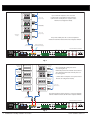
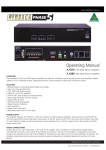
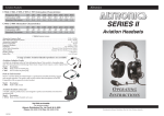
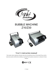
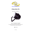
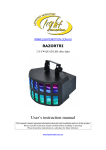
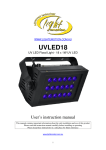
www.altronics.com.au
Operating Manual
A 4581 Alert/Evac/Chime/Cancel Remote Plate
Overview
The A 4581 wall plate allows remote triggering of the Alert, Evacuation and Chime tones and the cancel function of the
A 4575A Alert/Evacuation Controller. The switches are momentary operation and must be pressed for up to 3 seconds to
activate. The Alert and Evac switches have protective “flip up” covers to prevent accidental operation.
Connections
There are two RJ45 ports on the rear of the A 4581 wall plate, either of which can be used to connect to the A 4575A via
standard Cat5e cabling as shown in Fig 2. If the A 4581 has a connection problem with the A 4575A main unit the LED on
the wall plate will flash.
Remote triggering is only available when the A 4575A is in “Auto” mode which is selected by the key switch on the front
of the A 4575A. If the Alert, Evac and Chime switches on the A 4581 plate are pressed when the A 4575A main unit is in
“Manual” or “Isolate” mode, nothing will happen. The LED on the wall plate will illuminate when the A 4575A main unit
is in “Manual” or “Isolate” mode to alert the user that the wall plate is inactive.
If the Alert and Evac switches are pressed on the A 4575A while the unit is in “Manual” mode the corresponding Alert,
Evac and Chime switches on the A 4581 wall plate will illuminate.
ID
1
2
3
4
5
6
7
8
9
10
11
12
13
14
15
1
ON
OFF
ON
OFF
ON
OFF
ON
OFF
ON
OFF
ON
OFF
ON
OFF
ON
16
17
18
19
20
21
22
23
24
25
26
27
28
29
30
31
32
OFF
ON
OFF
ON
OFF
ON
OFF
ON
OFF
ON
OFF
ON
OFF
ON
OFF
ON
OFF
DIP Switch Settings
2
3
4
OFF OFF OFF
ON OFF OFF
ON OFF OFF
OFF ON OFF
OFF ON OFF
ON ON OFF
ON ON OFF
OFF OFF ON
OFF OFF ON
ON OFF ON
ON OFF ON
OFF ON ON
OFF ON ON
ON ON ON
ON ON ON
OFF
OFF
ON
ON
OFF
OFF
ON
ON
OFF
OFF
ON
ON
OFF
OFF
ON
ON
OFF
OFF
OFF
OFF
OFF
ON
ON
ON
ON
OFF
OFF
OFF
OFF
ON
ON
ON
ON
OFF
OFF
OFF
OFF
OFF
OFF
OFF
OFF
OFF
ON
ON
ON
ON
ON
ON
ON
ON
OFF
DIP Switch Settings
2
3
4
5
OFF
OFF
OFF
OFF
OFF
OFF
OFF
OFF
OFF
OFF
OFF
OFF
OFF
OFF
OFF
6
OFF
OFF
OFF
OFF
OFF
OFF
OFF
OFF
OFF
OFF
OFF
OFF
OFF
OFF
OFF
ID
33
34
35
36
37
38
39
40
41
42
43
44
45
46
47
ON
OFF
ON
OFF
ON
OFF
ON
OFF
ON
OFF
ON
OFF
ON
OFF
ON
OFF
ON
ON
OFF
OFF
ON
ON
OFF
OFF
ON
ON
OFF
OFF
ON
ON
OFF
OFF
OFF
ON
ON
ON
ON
OFF
OFF
OFF
OFF
ON
ON
ON
ON
OFF
OFF
OFF
OFF
OFF
OFF
OFF
ON
ON
ON
ON
ON
ON
ON
ON
5
OFF
OFF
OFF
OFF
OFF
OFF
OFF
OFF
OFF
OFF
OFF
OFF
OFF
OFF
OFF
6
ON
ON
ON
ON
ON
ON
ON
ON
ON
ON
ON
ON
ON
ON
ON
ON
ON
ON
ON
ON
ON
ON
ON
ON
ON
ON
ON
ON
ON
ON
ON
OFF
OFF
OFF
OFF
OFF
OFF
OFF
OFF
OFF
OFF
OFF
OFF
OFF
OFF
OFF
OFF
OFF
ON
48
49
50
51
52
53
54
55
56
57
58
59
60
61
62
63
OFF
ON
OFF
ON
OFF
ON
OFF
ON
OFF
ON
OFF
ON
OFF
ON
OFF
ON
OFF
OFF
ON
ON
OFF
OFF
ON
ON
OFF
OFF
ON
ON
OFF
OFF
ON
ON
OFF
OFF
OFF
OFF
ON
ON
ON
ON
OFF
OFF
OFF
OFF
ON
ON
ON
ON
OFF
OFF
OFF
OFF
OFF
OFF
OFF
OFF
ON
ON
ON
ON
ON
ON
ON
ON
ON
ON
ON
ON
ON
ON
ON
ON
ON
ON
ON
ON
ON
ON
ON
ON
ON
ON
ON
ON
ON
ON
ON
ON
ON
ON
ON
ON
ON
ON
ON
ON
1
Cascading the A 4581 plates
If more than one remote wall plate is required then the A 4581
wall plates can be cascaded together with only one connection
back to the A 4575A required as shown in Fig 2.
A Maximum of 16 plates is recommended, (If more than 16 wall
plates are required contact Altronics for configuration details).
There are two RJ45 ports on the rear of the A 4575A, either of
which can be used for connection to the wall plates.
The A 4575A also supports connection of the A 4578 wall plate
which is the same as the A 4581 but without the “Chime”
button. Both the A 4578 and A 4581 plates can be
connected to the A 4575A at the same time and in any
combination. Figure 3 illustrates one example.
Every wall plate must have a unique ID which is set by the DIP
switches which are accessed on the rear of the plate. A
maximum of 63 ID’s are available. Remove power before
changing DIP switch settings. The new settings will take effect
when power is returned.
Fig 1 Illustrates the DIP switch ID settings.
DIP Switches 7-8 are not used.
Fig 1
Redback® Proudly Made In Australia
User manual revision number: 1.0 11/11/2014
To next wall plate
Master unit
in manual
mode.
(Plate
Inactive)
Alert
Evac
Chime
Cancel
Master unit
in manual
mode.
(Plate
Inactive)
Alert
Evac
Chime
Cancel
Up to 16 A 4581 wall plates can be cascaded
together from a single RJ45 port of the A 4575A .
* (If more than 16 wall plates are required contact
Altronics for configuration details).
CAT5e cable
(Max 300 Metres)
CAT5e cable
(Max 300 Metres)
Master unit
in manual
mode.
(Plate
Inactive)
Alert
Evac
Chime
Cancel
CAT5e cable
(Max 300 Metres)
A 4581 Remote
Wall Plate
Master unit
in manual
mode.
(Plate
Inactive)
Alert
Evac
Chime
Cancel
If any of the A 4581 plates has a connection problem
with the A 4575A main unit the LED on the wall plate will flash.
Either of the RJ45 ports
of the A 4575A can be used.
CAT5e cable
(Max 300 Metres)
DIP Switches
1
(1A M205)
+ _
Interface 1
Interface 2
2
3
4
5
1 2 3 4
6
7
Tones
N/C
N/C
Alert
24V Out
N/O
N/C
Evac
24V Out
N/O
N/C
Volume
Chime
Bell
24V Out
N/O
Cancel
Evac
Alert
Bell
Contacts Contacts Contacts Contacts
DC FUSE 24V DC
IN
N/O
240V AC Fuse M205 500mA
A 4575A ALERT/EVAC CONTROLLER
Switched
24V Out
BGM
8
5 6 7 8
Fig 2
A 4578 Remote
Wall Plate
Alert
Evac
A 4581 Remote
Wall Plate
Cancel
Master unit
in manual
mode.
(Plate
Inactive)
Alert
Evac
Chime
Cancel
Alert
Evac
Chime
Cancel
Up to a maximum 16 wall plates can be
cascaded together. (*)
Both RJ45 ports from the A 4575A can be utilised.
Any combination of A 4578 or A 4581 plates can
be used together.
Master unit in manual mode (Plate Inactive)
A 4578 Remote
Wall Plate
Alert
Evac
A 4581 Remote
Wall Plate
Cancel
Master unit
in manual
mode.
(Plate
Inactive)
Master unit in manual mode (Plate Inactive)
A 4578 Remote
Wall Plate
Alert
Evac
Cancel
Alert
Master unit in manual mode (Plate Inactive)
A 4578 Remote
Wall Plate
Alert
Evac
Evac
Cancel
* (If more than 16 wall plates are required contact
Altronics for configuration details).
A 4578 Remote
Wall Plate
Master unit in manual mode (Plate Inactive)
Cancel
Alert
Master unit in manual mode (Plate Inactive)
Evac
Cancel
A 4578 Remote
Wall Plate
CAT5e cable
(Max 300 Metres)
Master unit in manual mode (Plate Inactive)
If any of the A 4578 or A 4581 plates has a connection problem
with the A 4575A main unit the LED on the wall plate will flash.
CAT5e cable
(Max 300 Metres)
DIP Switches
1
(1A M205)
+ _
Interface 1
Interface 2
2
3
4
1 2 3 4
5
6
7
Tones
N/C
N/C
Alert
24V Out
N/O
N/C
Evac
24V Out
N/O
Bell
24V Out
N/O
Volume
Chime
N/C
Cancel
Evac
Alert
Bell
Contacts Contacts Contacts Contacts
DC FUSE 24V DC
IN
N/O
240V AC Fuse M205 500mA
A 4575A ALERT/EVAC CONTROLLER
Switched
24V Out
BGM
8
5 6 7 8
Fig 3
2 Redback® Proudly Made In Australia
www.altronics.com.au