1
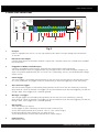
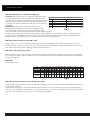
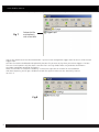
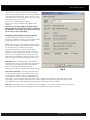
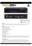
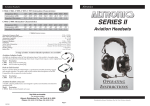
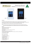
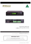
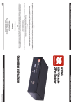
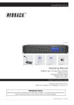
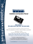
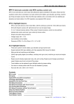
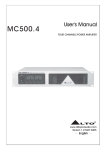
www.altronics.com.au
Operating Manual
A 1741 Message Player
The A 1741 is an MP3 based message player and tone generator designed for public address, security, customer direction
or emergency evacuation announcements.
1.0 Installation
Power requirements: The A 1741 needs a minimum of 12VDC at 300mA to work correctly. Maximum working voltage is
30VDC, do not exceed 30VDC as it will cause permanent damage to the unit. A good working voltage is between 12 and
24VDC. The power is connected via the 2.1mm (tip positive) DC socket on the rear of the unit (see fig 1).
Output: Output is via the stereo RCA connectors on the rear. Output level is nominal 500mV but is related to the recorded
level of the MP3.
Input triggers: The input triggers are activated by closing contacts on the rear of the unit whether by a normally open
switch or a timer or controller. (Note: These triggers have a common ground).
Trigger Switches: The messages can also be activated by pressing the switches on the front of the unit. Note: The Alert
and Evac buttons must be held down for 3 seconds before they activate. This reduces the chance of accidental triggering.
Switched output: The switched output terminal is triggered when any zone is activated. The voltage is the same as the
power supplied to the unit. ie if the A 1741 is powered by 12V, the switched output voltage will be 12V.
2.0 Play modes
Alternate: When the A 1741 is in Alternate mode (DIP1 switch1 OFF) (see Fig 3) the closing contact must be held for the
duration of the MP3 play time, if it is released before the MP3 ends the MP3 will stop playing immediately. If the contact is
held closed continually the MP3 will continue to loop over and over until the contact is released.
Momentary: In Momentary mode (DIP1 switch1 ON) (see Fig 3) a momentary closing contact or pulse on the trigger pins
will activate the MP3. The A 1741 will continue to play the MP3 till it finishes and will stop playing and wait for another
trigger activation.
To stop an MP3 playing when in Momentary mode the Cancel trigger or Cancel switch is used. A momentary closing
contact on the Cancel trigger or closure of the Cancel switch will stop the MP3 playing (it is recommended that the Cancel
contact or switch be held up to 2 seconds to ensure the MP3 stops playing)
User manual revision number 1.3 26/05/2015
www.altronics.com.au
3.0 FRONT PANEL CONNECTIONS
A 1741
Timer
Message Player
Switches
Disabled
1
2
3
4
Message Active
5
6
7
8
Alert
Evac
Cancel
On
Fault
SD CARD
16GB Maximum
1
Power
Hold down the Alert or Evac button for 3 seconds to activate
2
3
4
5 6
7
Fig 1
2
1
Switches Disabled Indicator
This LED illuminates when the front switches are set to be disabled via the DIP switches on the rear of the unit. (See Fig 2 for DIP Switch location).
2
SD card slot
The SD card which has the messages (in MP3 format) to be played is inserted here. The SD card can be a maximum of 16GB.
3
Message Active Switches and Indicators
These switches are used to trigger the messages 1-8. The LED’s inside the switches indicate when the
associated message is playing. The messages can also be activated by using the triggers on the rear of the unit. (See Fig 2 for details.) NOTE : If DIP switch 3 on the rear of the unit is set to “OFF” the front switches will not operate and the “Switches Disabled” LED will illuminate.
4
Alert and Evac Switches and Indicators
These switches are used to trigger the Alert and Evacuation tones (which conform to AS1670.4). The LED’s inside the switches indicate when the associated message is playing. The tones can also be activated by using the Alert and Evac triggers on the rear of the unit. (See Fig 2 for details.) NOTE : If DIP switch 3 on the rear of the unit is set to “OFF” the front Alert and Evac switches will not operate and the “Switches Disabled” LED willilluminate. The Alert and Evac tones can also be disabled from the rear triggers by setting DIP switch 2 to the “OFF” position. (See Fig 2 for details.)
5
Cancel Switch
Use this switch to cancel any MP3 which is playing. (This may need to be held down for 2 seconds to cancel).
The Cancel option can also be activated by using the Cancel trigger on the rear of the unit. (See Fig 2 for
details.) NOTE : If DIP switch 3 on the rear of the unit is set to “OFF” the front Cancel switch will not operate and the “Switches Disabled” LED will illuminate.
6
Status Led
This LED indicates whether the unit is ON or has a Fault condition. If the LED is “steady blue” the unit is receiving power. If the LED is “flashing red” then a fault has occured with the unit.
7
Power Switch
Used to turn the unit On or OFF.
Redback® Proudly Made In Australia
www.altronics.com.au
Triggers
-
+
1
Line Out
2
+
R
3
–
Cancel Evac Alert
8
7
6
4
3
2
1
1
0
1
0
0
1
1
1
0
1
1
1
Close
Contacts
to
Trigger
0
1
1
1
1
1
1
1
Expansion
Port
450
0
1
0
1
360
1
0
0
1
420
0
0
0
1
390
1
1
1
0
330
0
1
1
0
300
1
0
1
0
270
90
5
0
0
1
0
240
1
1
0
0
210
0
1
0
0
180
1
0
0
0
150
0
0
0
0
60
AUTO ALERT TO EVAC SWITCHOVER TIMER SETTINGS. 0 = OFF. 1 = ON.
120
L
DIP Switch Settings
SW
TRIGGER OPERATION & ALERT/EVAC SETTINGS
5
SW
ON
OFF
6
Triggers alternate
1 Triggers momentary
7
2
Alert/Evac OFF
Alert/Evac ON
8
Front switches active Front switches de-activated
3
Delay
(Sec.)
4
Not Used
30
12-30V DC
Switched
Out
OFF
12-30V DC
IN
DIP Switches
1
2
3
4
5
6
7
Manufactured in Australia By
Altronic Distributors Pty. Ltd.
www.altronics.com.au
4.0 REAR PANEL CONNECTIONS
8
1 2 3 4 5 6 7 8
4 5
6
7
8
Fig 2
1
DC Input
Power is supplied to the unit via a 2.1mm (tip to positive) DC socket. The input voltage must be between
12-30V DC.
2
RCA Stereo Line Output
Connect these outputs to the output amplifier. Output level is nominal 500mV but is related to the recorded level of the MP3.
3
Pluggable 12-30VDC switched output
Connects via Euroblock screw terminals. Please observe correct polarity when connecting.
The switched output terminal is triggered when any message or tone is activated. The output voltage is the same as the power supplied to the unit. ie if the A 1741 is powered by 12V DC, the switched output voltage will be 12V DC.
4
Cancel Trigger
The cancel trigger is activated by closing contacts on the rear of the unit whether by a normally open switch or a timer or controller. The trigger can be set to Momentary or Alternate triggering. See DIP SW settings.
5
Alert and Evac Triggers
The Alert and Evac triggers are activated by closing contacts on the rear of the unit whether by a normally open switch or a timer or controller. The triggers can be set to Momentary or Alternate triggering. See DIP SW settings. (Note: These triggers have a common ground).
6
Message 1-8 Triggers
The message triggers are activated by closing contacts on the rear of the unit whether by a normally open switch or a timer or controller. The triggers can be set to Momentary or Alternate triggering. See DIP SW settings. (Note: These triggers have a common ground).
7
DIP Switches
These DIP switches are used to:
Set the triggers as either momentary or alternate action. (Refer to Fig 3)
Set the Alert and Evacuation tones to either “ON” or “OFF”. (Refer to Fig 3)
Disable or Enable the front switches for use. (Refer to Fig 3)
Set the delay between the Alert and Evacuation tones. (Refer to Fig 4)
8
Expansion Port
Not currently used.
Redback® Proudly Made In Australia
3
www.altronics.com.au
5.0 DIP Switch Settings
(DIP SW 1) Momentary or Alternate triggering
Alternate: When the A 1741 is in Alternate mode (DIP switch1
TRIGGER OPERATION & ALERT/EVAC SETTINGS
OFF) the closing contact must be held for the duration of the
SW
ON
OFF
MP3 play time, if it is released before the MP3 ends the MP3 will
Triggers
momentary
Triggers
alternate
1
stop playing immediately. If the contact is held closed continual2
Alert/Evac OFF
Alert/Evac ON
ly the MP3 will continue to loop over and over until the contact
Front switches active Front switches de-activated
3
is released.
4
Not Used
Momentary: In Momentary mode (DIP switch1 ON) a
momentary closing contact or pulse on the trigger pins will
Fig 3
activate the MP3. The A 1741 will continue to play the MP3
till it finishes and will stop playing and wait for another trigger activation.
To stop an MP3 playing when in Momentary mode the Cancel trigger or Cancel switch is used. A momentary closing
contact on the Cancel trigger or closure of the Cancel switch will stop the MP3 playing (it is recommended that the
Cancel contact or switch be held up to 2 seconds to ensure the MP3 stops playing).
(DIP SW 2) Alert/Evacuation Tones ON or OFF
When switch 2 is set to “OFF” the Alert and Evac tones cannot be triggered either by the front switches or the rear
terminal contacts. If switch 2 is set to “ON” the Alert and Evac tones can always be triggered via the rear terminal contacts. However the front switch triggering is dictated by DIP Switch 3.
(DIP SW 3) Front Switch Activation
When switch 3 is set to “OFF” the front switches become de-activated from use. When these switches are de-activated
the “Switches Disabled” LED on the front of the unit will illuminate. This function disables all the switches including the
cancel, alert and evac.
(DIP SW 4)
Not currently used
0
0
1
1
1
0
1
1
0
1
1
1
1
1
1
1
450
1
1
0
1
420
0
1
0
1
390
1
0
0
1
360
0
0
0
1
330
1
1
1
0
300
0
1
1
0
270
1
0
1
0
240
90
0
0
1
0
210
1
1
0
0
180
0
1
0
0
150
1
0
0
0
120
0
0
0
0
60
AUTO ALERT TO EVAC SWITCHOVER TIMER SETTINGS. 0 = OFF. 1 = ON.
30
5
6
7
8
Delay
(Sec.)
OFF
SW
Fig 4
(DIP SW 5-8) Alert/Evacuation Tones change over option
The Alert and evacuation tones conform to Australian Standards AS1670.4 and are used to notify building occupants of
an emergency situation.
The Alert tone comes with a change over option which forces the A 1741 to switch from the Alert to the Evacuation
tone after a prescribed time. DIP switches 5-8 set these change over times from 30 seconds to 450 seconds in 30 second
intervals. If all DIP switches are set to “OFF” the changeover is disabled.
4
Redback® Proudly Made In Australia
www.altronics.com.au
6.0 Putting MP3’s on to the Player
You will first need to remove power from the A 1741 then remove the SD card from the front of the unit.
To remove the SD card push the card in and it will eject itself.
The SD card will then need to be connected to a PC. You will need a PC equipped with a SD card reader to do this (not
supplied).
Step by step guide to put a MP3 into Trigger1 with a Windows installed PC
Step 1: Make sure the PC is on and card reader connected and correctly installed. Then insert the SD card into the reader.
Step 2: Go to “My Computer” (figure 2) and open the SD card which is usually marked “Removable disk”.
In this case it is named “Removable disk (G:)”
Fig 5
Open
Removable Disk
You Should get a window that looks like figure 6.
Fig 6
Trigger 1 Folder
Redback® Proudly Made In Australia
5
www.altronics.com.au
Step 3: Open folder named “trig1” and you should get a window that looks like figure 7.
Fig 7
Delete this file
and replace it
with a new MP3
Step 4: You should see an MP3 file XXXXXX.MP3 if you have never changed the trigger1 MP3 file then it will be named
Trigger1.MP3.
This MP3 file needs to be deleted and replaced by the MP3 file you want to play when you activate trigger1. The MP3
file name is not important only that there is one MP3 file in the trig1 folder. Make sure you delete the old MP3!
The folder should look something like figure 8.
NOTE the new MP3 file cannot be “Read only” to check this right click on the MP3 file and scroll down
and select Properties, you will get a window that looks like figure 9. Make sure the “Read Only” box has
no tick in it.
Fig 8
6
Redback® Proudly Made In Australia
www.altronics.com.au
The new MP3 is now installed on the card and the
card can be removed from the PC following windows
safe card removal procedures. Make sure the A 1741
is OFF and insert the SD card into the slot in the front;
it will click when fully inserted.
The A 1741 is ready to go on Trigger1.
Repeat these steps for Trigger2 to Trigger8 if you
need to.
Please note: that the ALERT and EVAC folders
and the MP3 files inside these folders should not
be deleted or renamed in anyway this will cause
the A 1741 to stop responding.
Emergency tones (Alert and Evacuation)
The Alert and evacuation tones conform to
Australian Standards AS1670.4 and are used to notify
building occupants of an emergency situation.
Alert: The Alert tone is activated by a closing contact
on the ALERT trigger or by pressing the Alert button
on the front of the unit and can be used in
Alternate or Momentary setup as mentioned in
section 2.0 and the Dip Switch settings. The Alert
tone comes with a change over option which forces
the A 1741 to switch from Alert to the Evacuation
tone after a prescribed time. Use DIP switches 5-8 to
adjust this time or switch off completely (see Fig 4).
Evacuation: The Evacuation tone is activated by a
closing contact on the Evac trigger or by pressing the
Evac button on the front of the unit and and can
be used in Alternate or Momentary setup as
mentioned in section 2.0 and the Dip Switch settings.
Fig 9
Evacuation message: A message (repeated twice)
can be inserted every three evacuation cycles as per
the Australian Standards. Voice message could be
something like “please evacuate the building by the
closest exit”. To install a Evacuation message on the A 1740 follow the Step by step guide to put a MP3
into Trigger1 with a Windows installed PC but replace Trigger1 with Voice i.e. put the message into the
Voice folder on the SD card and delete any other MP3 file located in the voice folder.
Priority: The Emergency tones have priority over other triggers (1 to 8) and if activated will stop any other
MP3 and activate the selected emergency tone. Evacuation also has priority over Alert.
Redback® Proudly Made In Australia
7
www.altronics.com.au
7.0 Troubleshooting
NO Power (Power LED does not illuminate):
Check power supply DC jack is 2.1mm and not 2.5mm size.
Power supply voltage is 12-30VDC.
Power supply is a DC output, not AC.
Message active 10 LED flashs all the time:
This is an indicator that the SD card is not inserted correctly or is not formatted. Make sure all folders
on the SD card are as per figure 6.
Emergency tones do not work:
Switch DIP switch 2 ON to activate emergency tones.
8.0 Specifications
Power supply: .................. 12VDC to 30VDC 300mA (idle/maximum current draw 150mA) tip positive
Output: .................................................................................................. Stereo RCA 500mV nominal
MP3 sample rate: ...................................................................................................................... 44kHz
SD card size: .............................................................................................................. 256MB to 16GB
Trigger activation: ......................................................................................................Closing contact
Switched output: ............................................................... 12-30VDC out (supply voltage dependant)
MP3 info:
Length/size: ................................ Limited by card size (800mins @ 128kbps, 44kHz on supplied 8GB)
Bit rate: .................................................................. All standard MP3 rates (128kbps recommended)
Sample rate: ............................................................... All standard MP3 rates (44kHz recommended)
Channels: .................................................................................................................. Stereo or mono
* Specifications subject to change without notice.
Distributed by Altronic Distributors Pty. Ltd. Perth. Western Australia.
Phone: 1300 780 999 Fax: 1300 790 999 Internet: www.altronics.com.au
8
Redback® Proudly Made In Australia