1
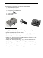
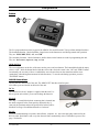
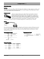
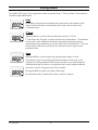
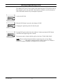
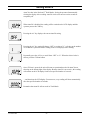
UET Series Torque Analyzer
Operations Manual
PO Box 16460, Portland, OR 97292-0460 z 800-852-1368 z Fax 800-582-9015
Quick Start Guide
When unpacking the UET Series tester, ensure that you have all six components.
1. UET Series Instrument (as pictured)
2. Rundown Fixture (joint simulator)
3. Power bit to engage bolt in Rundown fixture
4. Security Key
5. AC Power & Battery Charger
6. Operations Manual
Please read manual prior to using
1. Insert key into center I/O (as pictured).
2. If using a power tool, insert rundown fixture into female square of transducer; if using a manual
torque tool, insert bit adapter directly into transducer female square.
3. Push the “On” button (the white circle with a white dot).
4. The unit will default and only be active in the first direction used (CW or CCW); to use in the other
direction, simply press the “On” button to re-zero the instrument and re-initialize zero.
5. Using the “PGM” button, select L.O. to “OFF” (press enter after selection).
6. Using the “PGM” button, select Filt (for Pulse tools & Click wrenches, at least 1000; for all other
tools, 500 is sufficient; press enter after selection).
7. Using the “MDE” button, select torque mode (Pk, 1st Pk or Track); -Pk is for Power tools, Dial
wrenches, and Preset torque limiting tools; 1st Pk is for Click type tools
8. Using the “ENG” button, select the desired engineering unit (IN LB, IN OZ, Kgf m, KgfCm, gfCm,
cNm, Nm and FTLB).
9. Using the “A/C” button, select time for AutoClr or turn off (this automatically clears the display after
selected time; press enter after selection).
10. If not using AutoClr, press the “CLR” button to clear display.
Table of Contents
Page
Number
1. Introduction
y
Features
- Clockwise and Counterclockwise Operation
2. Components
y
Buttons
- Off & On/Zero
y
Unit IO Connections
- DC In
- Keylock
- RS-232
y
Other Components
- Batteries
- Rundown Fixtures
- RS-232
3. Setting Modes
y
Peak
st
1
1
1
2
2
2
2
2
2
2
3
3
3
3
4
4
y
1 Peak
4
y
Track
4
4. Setting Engineering Units
5
5. Setting AutoClr
6
6. Programming
7
y
Set Filter
7
y
Sleep Mode
7
y
Lock-Out Mode
8
7. Calibration
8
Introduction
Thank you for purchasing the UET Series torque testers from AIMCO. We sincerely appreciate your business.
The UET Series instruments demonstrate AIMCO’s ongoing pursuit of product excellence and total customer
satisfaction.
The AIMCO Universal Electronic Tester is designed specifically for the requirements of today’s production
facilities. Small, portable, accurate, durable, and most importantly, this tester is very easy to use.
Please read through this manual prior to using your tester and if you have any questions, please call us at:
(800) 852-1368 for Customer Service.
Features
•
Keylock security
•
RS-232 data output
•
Simple, one-button operation
•
Dedicated, integrated transducer in horizontal or vertical configurations
Clockwise and Counterclockwise Operation
The AIMCO Universal Electronic Tester is capable of operating in both the clockwise and counterclockwise
directions. Please Note: If a unit is not calibrated in the counterclockwise direction, it will not function in the
counterclockwise direction and the “OVERLOAD” flag will appear.
Please Note: When working in Peak or First Peak modes, the default direction (CW/CCW) is set by the first
torque measurement. To change direction, the unit must be zeroed (press the On/Zero key) before taking a
measurement in the opposite direction.
To ensure accuracy, you should always remove hysteresis when changing the direction of torquing. [By loading
the transducer to 90% FSD in the direction of intended use several times (3 to 5)].
November 2006
-1-
Components
Buttons
Off
On/Zero
The five program buttons on the keypad of the AIMCO Universal Electronic Tester perform multiple functions.
The dominant function - labeled in bolder, larger letters on the buttons are used during normal unit operation.
They are: PGM, MDE, ENG, A/C, and CLR.
The secondary functions - labeled in thinner, smaller letters on the buttons are used for programming the unit.
They are: down arrow, up arrow, step, and ent.
Off & On/Zero
The two oval buttons on the face of the tester are the power and zero buttons. The button labeled with the empty
circle is “OFF” while the button labeled with the circle with a dot in the center is the “ON” and “ZERO” button.
Occasionally, the user may wish to re-establish the zero reference between the transducer and the tester
(particularly when taking measurements in both directions). To zero the unit during operation, press the
“ON/ZERO” button.
Unit IO Connections
The IO ports are on the back of the unit. The AIMCO UET has three interface ports.
All of these ports are labeled on the back of the unit.
DC In
The interface for the AC Adapter is supplied with the unit. Use
this to operate unit with AC power and recharge the batteries.
Keylock
The “key” is a small, black plastic connector that is inserted into
the small receptacle in the center position. When this key is
removed, the functions and modes specified for lockout will be
disabled. See Page 8 for additional details on “lockouts”.
RS-232
If you are communicating to a printer, data collector, computer, etc., this is the mini-plug connector for the
RS-232 cable. Serial data is sent every time the unit clears automatically or the CLR button is pressed. See
page 3 for details.
November 2006
-2-
Components (cont.)
Other Components
Batteries
The AIMCO UET testers employ a dedicated charging circuit. With the AC adapter plugged in, the battery will
fully charge in approximately 3 hours; the system can be used while charging. Fully charged batteries should
provide approximately 16 hours of continuous use.
Rundown Fixtures
Each unit is shipped complete with a rundown fixture (joint simulator). The above
illustration demonstrates the Rundown Fixture. The washer stack is comprised of
belleville washers, designed to compress as the bolt tightens. By varying the arrangement of these washers, various joint rates can be simulated. To test power tools, it is
necessary to use joint simulators. The joint simulator has a male square drive which is
inserted into the female square of the transducer. This Rundown Fixture can be
configured from a hard to a soft joint. The standard configuration is a medium joint up to 1,000 in-lb.
RS-232
Ground
Transmit
Every time the unit clears a reading, whether through the AutoClr function or when the CLR button is pressed,
the value is transmitted through the RS-232 port. This value is transmitted as serial data and can be read by a
printer, computer, or data collector. RS-232 cable sets are not included with the system but may be ordered
separately as an accessory.
RS232 Transfer Protocol
Protocol
RS32 Datastream Format
sdddddbuuuuucl, where:
s
Sign (space or -)
Value
Cable
9 pin to mini-plug
Baud
9600
d
Data with Decimal Point
None
u
Units
Parity
Bits
8
S Bit
1
Handshake
Xon, Xoff
RS232 Cable Pinouts
Pin #
Description
Pin #
Description
1
Unused
6
Unused
2
Transmit
7
Unused
3
Receive
8
Unused
4
Unused
9
Unused
5
Ground
November 2006
-3-
c
Carriage Return
l
Line Feed
Setting Modes
The AIMCO UET Series Testers support three modes of operation: Peak, 1st Peak, and Track. These modes are
selectable with the MDE button.
Peak
Peak displays and retains the maximum torque experienced by the transducer. Peak
mode is used for dial torque wrench testing, preset torque tools, and power tool
verification/testing.
1st Peak
When the MDE key is pressed, the operating mode switches to 1st Peak.
1st Peak detects the “first peak” of torque experienced by the transducer. 1st Peak mode is
used for click wrench calibration and testing; capturing the initial peak torque by
monitoring the torque signal drop as it occurs when a click wrench actuates. 1st Peak can
reduce operator influences to provide the user with more accurate torque wrench
performance data.
Track
When the MDE key is pressed again, the operating mode switches to Track.
Track displays torque as it is being applied to the transducer. Track mode is used
primarily for verifying calibration of the unit and can also be used when testing and
calibrating dial torque wrenches or in conjunction with a torque loading mechanism.
Notice that “AutoClr” disappears when Track is enabled.
Pressing the MDE key again cycles back to Peak mode.
Now that the mode has switched back to Peak, “AutoClr” reappears.
November 2006
-4-
Setting Engineering Units
The AIMCO UET Series Testers support eight engineering units: FT LB, IN LB, IN OZ,
Kgf m, KgfCm, gfCm, Nm, and cNm. These units are selectable on the fly through use
of the ENG button which will cycle through all eight units.
A unit set for IN LBs.
When the ENG button is pressed, units change to IN OZ.
Changing the engineering units will clear the peak.
Pressing ENG again switches the units to Kgf m. Continue pressing the ENG button
until the desired engineering unit is reached.
The selection order is: Kgf m, KgfCm, gfCm, cNm, Nm, FT LB, IN LB, IN OZ.
NOTE: When scrolling through the different engineering units, an Over-Range
designator “_ _ _ _” may appear, signifying an out-of-range selection. For example, a
1,000 ft. lb. system would show over-range if In Oz was selected.
November 2006
-5-
Setting AutoClr
AutoClr works in the Peak and 1st Peak Modes, freeing the operator from manually
clearing the display after a reading. AutoClr can be set from one to nine seconds or
completely off.
When AutoClr is disabled, the reading will be retained on the LCD display until the
operator presses the CLR key.
Pressing the A/C key displays the current AutoClr setting.
Pressing the A/C key again will change “OFF” to a value of “1”, referring to the number
of seconds the system will hold a reading on the LCD display before clearing.
Repeatedly press the A/C key to scroll from “OFF” to “9”. When the desired value is
shown, press the CLR/ent button.
Once CLR/ent is pressed, the unit will return to operational mode with AutoClr now
showing on the bottom-right of the display. Because AutoClr is now active, this reading
will remain on the LCD display for the user-specified number of seconds…
…and then clear the LCD display. From now on, every reading will clear automatically
after the specified number of seconds.
Remember that AutoClr will not work in Track Mode.
November 2006
-6-
Programming
The Program Key (PGM) is located on the front panel. Pressing the Program Key
repeatedly will cycle through the following Program Functions (please see the associated
sections for details about each function). To deactivate the program button and lockout
selected features, remove the tamper-key on the left side of the unit.
Set Filter
The filter is used to set the Hz speed at which the unit will capture peak. Press the PGM
key one time to access the Set Filter Function. This example shows a unit set at 500 Hz.
Pressing the Up Arrow key will increase the value by 500 to 1000 Hz.
Pressing the Up Arrow key again will increase the value by 500 to 1500 Hz.
Pressing the Up Arrow key again will increase the value by 500 to 2000 Hz.
Press the Up Arrow key again and the value will cycle back to 500 Hz.
You can also use the down arrow key to cycle through the Hz settings but in decreasing
order.
When finished, press the CLR/ent key to accept the value and return to operational
mode, or press the PGM key to accept the value and continue to the next Program
Function.
Sleep Mode
To conserve battery life, these testers are equipped with a “sleep” mode, which sets the
unit to standby after a user-selectable of time has passed without activity. To access the
sleep mode, press the PGM key four times. This example shows sleep turned off.
Press the Up Arrow key to increase the number of minutes the unit will wait for input, or
press the Down Arrow key to decrease the number. This example shows a value of four
minutes.
The highest possible sleep setting is 20 minutes. Press CLR/ent to accept the value and
return to operational mode, or press the PGM key to accept the value and continue to the
next function.
November 2006
-7-
Programming (cont.)
Lock-Out Mode
For security reasons, it may be desirable to limit the modes and functions available to the
personnel using this equipment. The Lock-Out Mode enables the user to specify the
modes and functions unavailable to others and ensure security by removing the Program
Key located on the back side of the unit.
Use the Up Arrow or Down Arrow keys to cycle through all the possible lockout
choices. This example indicates that after the program key is removed, the operator will
not be able to change the unit’s operation mode.
This example indicates that after the program key is removed, the operator will not be
able to change the status of AutoClr.
This example indicates that after the program key is removed, the operator will not be
able to change the unit’s operation mode or change the status of AutoClr.
This example indicates that after the program key is removed, the operator will not be
able to change the unit’s operation mode or engineering units.
x
The possible lockout options are: Mode, AutoClr, Mode & AutoClr, Engineering
Units, Mode & Engineering Units, AutoClr & Engineering Units, Mode, AutoClr,
& Engineering Units, and None (OFF).
Calibration
We strongly urge against customer use of the calibration function. This is used by AIMCO or AIMCO-approved
Service Centers for the calibration of transducers to displays.
November 2006
-8-
Corporate Headquarters
1204 E Maple Road
Troy, MI 48083
248-583-1180
248-583-7115 (Fax)
10000 SE Pine Street
Portland, OR 97216
800-852-1368
800-582-9015 (Fax)
www.aimco-global.com
Ave. Morones Prieto 2110 Pte.
Col. Loma Larga, Monterrey, NL CP 64710
Mexico
011-52-81-1001-1600
011-52-81-1001-1630 (Fax)
LIT-MAN252
© 2006 AIMCO