1
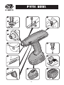
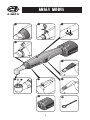
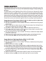
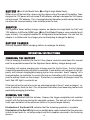
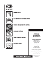
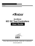
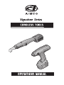
C O R D L ES S T O O L S
O P E R AT I O N S M A N U A L
P I ST O L M O D EL
D
3
C
2
B
1
a
4
E
F
5
11
L
G
6
K
10
H
7
I
8
J
9
2
b
A N G L E M O D EL
B
1
E
4
D
3
a b
2C
F
5
I
8
H
7
G
6
J
9
K
10
c
3
Thank you for your purchase of a Signature Series Precision Clutch Cordless Tool from
AIMCO. The Signature Series follows the concept of PERQ™ adding to your company’s
Productivity, Reliability, Ergonomics and Quality demands as part of the most comprehensive line of assembly tools available from a single source worldwide.
TA B L E O F C O N T E N T S
Pistol Model Diagram .....................................................................................2
Angle Model Diagram .....................................................................................3
General Safety Guide......................................................................................4
Signature Series Tool Components
LED Display ......................................................................................5
Torque Adjustment.............................................................................6
Quick Change Chuck / Anvil ...............................................................7
Workpiece Lights...............................................................................7
Trigger..............................................................................................7
Rotation Selection Switch ..................................................................7
Battery..............................................................................................8
Adapter ............................................................................................8
Battery Charger.................................................................................8
Operating Instructions
Charging the Battery..........................................................................8
Running the Tool ...............................................................................8
Maintenance & Repair ....................................................................................9
Accessories....................................................................................................9
Warranty......................................................................................................10
Declaration of Conformity .............................................................................11
1G E N E R A L
S A F ET Y G U I D E
Do not use this tool before you have completely read and understood this Operations
Manual, the Operations Manual for the associated Battery Charger, and any Signature Series Accessories Manuals intended for use with this tool.
Please observe all relevant local safety practices including the use of eye and ear protection.
This manual should be kept in an accessible location for later use and passed along to
any new users.
Secure the workpiece firmly. A workpiece that is gripped tightly by a holding device or
immobilized is more secure than if held by hand.
Hold tool securely in the hand prior to activating the trigger. It is possible that an inertial
reaction may occur on some applications.
Do not screw, rivet, or engrave nameplates or signs onto tool housing. Should the tool
4
housing become damaged, its insulating properties could become adversely effected,
causing a potential for shock. The use of labels for identification purposes is recommended.
Ventilation slots in tool housing should be kept clean. Accumulation of metallic dust can
cause an electrical hazard and reduce the performance of the tool.
Always remove the battery from the tool before commencing any work on the tool itself
or transporting it. This will eliminate the possibility of the tool starting unintentionally.
DO NOT OPEN THE BATTERY. The battery is nonuser serviceable and should be recycled
in accordance with local regulations. Contact your AIMCO Signature Series dealer for
assistance in locating recycling programs in your area.
Do not throw the battery into a fire or expose it to high temperatures. As with any battery,
this can lead to an explosive condition.
Never look directly into the LED lights of the power tool or shine it into other’s eyes as
this could be harmful to someone with light sensitivity.
S I G N AT U R E S E R I E S T O O L C O M P O N E N T S
L E D D I S P L AY
G R EE N L I G H T (Ba on Pistol Model, Ea on Right Angle Model)
■ Illumination after cycle completion indicates a torque has been delivered and the
clutch has successfully shut off the tool
■ Flashing Green in combination with Red indicates counter clockwise (CCW) rotation
is activated
R E D L I G H T (Bb on Pistol Model, Eb on Right Angle Model)
■ Illumination without an audible beep indicates that the trigger was activated while
the battery was being installed onto the tool. The tool will not activate until the light
has gone out. Should the light remain lit, this is an indication that the trigger switch
requires service
■ Illumination of the light accompanied by an audible beep indicates that the tool
has stopped running without torque delivery and successful clutch shut off. The tool
may be restarted immediately to either retry the same application or to proceed on
to a new one.
■ Flashing once per second indicates that the battery is too low to accomplish tightening functions and needs to be re-charged.
■ Flashing twice per second indicates that the tool has overheated and the protection
circuit is engaged. After cooling, the tool will once again be ready for operation.
Should the overtemperature circuit be activated repeatedly in a short time, the tool
should be examined by an authorized AIMCO Signature Series repair center. As with
any electric tool, overheating may be caused by use in excess of its duty cycle.
20 - 25 fastenings per minute is a good guide for electric tool duty cycles. This is only
a guide, as the specific application will determine the actual working load of the tool.
5
T O R Q U E A D J U ST M E N T
Each Signature Series tool is built with a precision clutch and is adjusted by use of the
supplied adjustment tool. This insures that unauthorized changes in torque settings do
not occur.
The adjustment on each Signature Series clutch will increase or decrease the torque
output of the tool in a relative manner. To insure that the precise torque delivery features of the tool are optimized, it is recommended to use an Auditor® Series desktop
torque tester to verify the setting of the tool once an adjustment has been made. This
will insure that the amount of torque being output by the tool is known prior to putting
the tool into service and checked at regular intervals according to plant procedures.
Torque Adjustment: Pistol Models (SPC-P-2, SPC-P-4, SPC-P-6, SPC-P-9, SPC-P-9H)
■ Requires use of supplied Adjustment Tool (L)
■ Run tool on Torque Tester, such as Auditor® UET Series, to determine existing torque
output of tool.
■ Open sliding door by depressing rear end of the door (away from driving bit) and
sliding door towards the rear of the tool. (C)
■ Once door is open, rotate bit until tab is visible for adjustment tool to fit in.
■ Rotate adjustment tool clockwise (CW) to increase torque output, or counter clockwise (CCW) to decrease torque output. (D)
■ Run tool on Torque Tester, such as Auditor® UET Series, to determine torque output
of tool after adjustment.
■ Repeat procedure until desired torque output has been set into the tool clutch.
■ Close sliding door (C) and return adjustment tool to secure location.
Torque Adjustment: Right Angle Models (SPC-R-16, SPC-R-25)
■ Requires use of supplied Adjustment Tool (K)
■ Run tool on Torque Tester, such as Auditor® UET Series, to determine existing torque
output of tool.
■ Remove adjustment window cap (C)
■ Once window is open, rotate collar until tab is visible for adjustment tool to fit in.
■ Rotate adjustment tool clockwise (CW) around the tool axis to increase torque output
or counter clockwise (CCW) around the tool axis to decrease torque output. (D)
■ Run tool on Torque Tester, such as Auditor® UET Series, to determine torque output
of tool after adjustment.
■ Repeat procedure until desired torque output has been set into the tool clutch.
■ Replace window cap (C) and return adjustment tool to secure location.
6
QU I C K C H AN G E C HU C K / A NVI L
Each Signature Series tool performs to its optimal level when used in combination with
industrial quality bits/sockets from AIMCO.
Pistol Models (SPC-P-2, SPC-P-4, SPC-P-6, SPC-P-9, SPC-P-9H)
■ Each Pistol Model Tool contains a ¼” Quick Release type chuck (E) accepts standard
¼” Power Drive style driving bits
Right Angle Models (SPC-R-16, SPC-R-25)
■ Each Right Angle Model Tool contains a 3/8” Square Drive anvil (I) for use with
industrial grade sockets. The tool anvil has a spring loaded locking pin for socket
retention. To install or remove the driving socket from the tool, depress the locking
pin slightly with a pick or other device to enable the socket to go onto or come off of
the tool.
W O R K P I EC E L I G H T S
Each Signature Series tool contains built-in LED lights that illuminate the workpiece to
assist the operator.
■ Pistol Model Tools contain lights (F) that activate when trigger is depressed halfway.
These lights remain illuminated throughout the fastening cycle.
■ Right Angle Model Tools contain lights (H) that illuminate when depressing the trigger
halfway to maximize battery life. Once the tool begins the tightening cycle, these
lights shut off automatically.
TR IG G E R
To start the fastening cycle, depress the trigger completely (H on Pistol Model Tools,
F on Right Angle Model Tools)
To activate the LED lights only, depress the trigger halfway (H on Pistol Model Tools,
F on Right Angle Model Tools)
R O TAT I O N S EL EC T I O N SW I T C H
(G)
To change the direction of rotation, simply depress the rotation direction switch. This will
cause the tool to switch from clockwise (CW) to counter clockwise (CCW) rotation for one
activation of the trigger. Once the trigger is released, the tool will automatically return to
clockwise (CW) rotation insuring that the tool is ready to be productive at all times.
Pistol Models (SPC-P-2, SPC-P-4, SPC-P-6, SPC-P-9, SPC-P-9H)
■ Rotation Selection Switch is located in front of trigger and is built as a pair to accommodate right or left handed operators (G)
Right Angle Models (SPC-R-16, SPC-R-25)
■ Rotation Selection Switch is located in a recess in front of trigger. Button is recessed
to avoid accidental activation (G)
7
B AT T E RY
(I on Pistol Model Tools, J on Right Angle Model Tools)
Slides on or off the tool after depressing the release clip at the rear of the battery. Tools
designed for 12V power will not accept 9.6V batteries and tools designed for 9.6V power
will not accept 12V batteries. This is accomplished by the battery mount design that does
not allow the incorrect battery to be installed onto the tool.
A D A PT E R
The Signature Series battery charger requires an adapter to accept both the 9.6V and
12V batteries in NiCad or NiMH types (J on Pistol Model Diagram, same adapter for all
types of tools). The supplied adapter fits all Signature Series batteries. Be sure that the
adapter is installed onto the charger prior to attempting to charge the battery.
B AT T E RY C H A R G E R
Use only Signature Series charging stations to recharge the battery.
O P E R AT I N G I N ST R U C T I O N S
C H A R G I N G T H E B AT T E RY
Prior to charging the battery for the first time, please read and understand this manual
and the associated manual for the Signature Series battery charger being used.
The battery will require charging prior to being used for the first time. The first charge
should take approximately one hour to complete. A new battery will not reach its full capacity until several charging/discharging cycles have occurred. Avoid “topping” off a
charged battery to maximize its service life and use the battery until it has discharged,
prior to putting it back on the charger. The battery is completely discharged when the
tool’s Red LED light is constantly on.
If the tool will not be put into use for an extended period of time (1 week or longer), remove the battery from the tool. This will prevent the battery from becoming too low and
potentially damaging the battery.
RU N NI N G TH E T OO L
Engage the bit/socket onto the fastener. Depress the trigger completely and maintain
contact with the fastener during the complete rundown. The tool will shut off automatically upon activation of the precision clutch at its preset torque delivery.
Illumination of the Green LED indicates that the fastening operation is complete.
Illumination of the Red LED light and an audible beep sound indicate that the precision
clutch did not reach its set torque output and that a problem occurred in the fastening
process.
8
Failure of the tool to run is an indication that the battery does not contain a sufficient
charge or is incorrectly installed onto the tool. A solid Red LED light indicates a low battery while no LED lights indicate a poorly connected battery.
M A I N T E N A N C E A N D R E PA I R
Signature Series tools contain few user serviceable parts and are designed to be low
maintenance. The following are recommended maintenance procedures to be performed
once per week or more often in high usage applications:
■ Visually check to be sure that battery contacts are clean. Should cleaning be required,
the use of a non-residue, electrical contact cleaner is recommended.
■ Visually inspect the tool housing to insure that no cracks or degradation of the material is evident. Should cracking or deep abrasion be noted, please send the tool to
an authorized AIMCO Signature Series service center for estimate and repair.
■ Lubrication of the gearbox is recommended after the installation of 250,000 fasteners
with the tool.
● Lubrication should only be performed after reading and understanding the tool
parts list and assembly diagram. (Separate document)
● Remove Phillips screws (part #9) from the tool handle and carefully separate the
housing to expose clutch and gear assemblies. Remove each assembly (clutch
and gear set) from handle assembly.
● Add light coating of black moly type grease (Shell Alvonia #2, Mobil Plex 2, MobilPlex 47 or Chevron Moly Grease #2) to Planetary Gear Set. Be sure to lightly
coat gear surfaces and not overlubricate as a reduction in tool performance will
occur.
● Add light coating of grease to ball bearings in clutch assembly at Cam Ring
(part #50).
● Be certain to replace any worn or damaged parts discovered with the assistance
of a local AIMCO Signature Series Service Center
● Reassemble tool in reverse order of above and test.
All other items on the tool are nonuser serviceable. Any repairs should be directed to
an authorized AIMCO Signature Series repair center for estimate and repair.
A C C ES S O R I ES
Use only authorized AIMCO Signature Series Accessories.
9
WA R R A N T Y
NEW TOOL AND ACCESSORY WARRANTY
Any new tool or accessory branded with the AIMCO, Uryu, AcraDyne or Eagle Industries name,
and purchased from AIMCO, or through one of its authorized distributors or agents, is warranted to the original buyer against defects in materials and workmanship for a period of one
(1) year* from date of delivery. Under the terms of this warranty, AIMCO agrees without charge
to repair or replace, at its option and F.O.B. its authorized service centers, any product or accessory warranted hereunder proving to AIMCO's satisfaction to be defective as a result of
defective workman-ship or material. In order to qualify for this warranty, written notice to
AIMCO must be given immediately upon discovery of such defect, at which time AIMCO will
issue an authorization to return the tool. The defective item must be promptly returned to an
authorized AIMCO service center with all freight charges prepaid.
REPAIRED TOOL WARRANTY
Once a tool is beyond the new product warranty period as detailed above, AIMCO will provide
repair subject to the following warranty periods: pneumatic tools: 90 days*; electric tools and
Acra-Feed: 90 days; battery tools: 30 days*; DC Electric tools: 90 days*
EXCLUSION FROM WARRANTY
This warranty is valid only on products purchased from AIMCO, or thru its authorized distributors or agents. AIMCO shall have no obligation pursuant to the AIMCO Warranty with respect
to any tools or accessories which in AIMCO's sole judgment have been altered damaged, misused, abused, badly worn, lost or improperly maintained.This Warranty is null and void if the
customer, or any other person other than an authorized representative of AIMCO, has made
any attempt to service or modify the tool or accessory prior to its return to AIMCO under this
Warranty.
The warranty provision with respect to each such product may be amended by AIMCO from
time to time in its sole discretion.The liability of AIMCO hereunder shall be limited to replacing
or repairing, at its option, any defective products which are returned F.O.B. to AIMCO or, at
AIMCO's option, refunding the purchase price of such products.
AIMCO reserves the right to make periodic changes in construction or tool design at any
time. AIMCO specifically reserves the right to make these changes without incurring any obligation or incorporating such changes or updates in tools or parts previously distributed.
THE AIMCO WARRANTY IS IN LIEU OF ALL OTHER WARRANTIES, EXPRESSED OR IMPLIED,
AND AIMCO EXPRESSLY DISCLAIMS ANY WARRANTY OF MERCHANTABILITY OR FITNESS
FOR A PARTICULAR PURPOSE.THIS WARRANTY SETS FORTH THE SOLE AND EXCLUSIVE REMEDY
IN CONTRACT, TORT, STRICT LIABILITY, OR OTHERWISE.
THIS WARRANTY IS THE ONLY WARRANTY MADE BY AIMCO WITH RESPECT TO THE GOODS
DELIVERED HEREUNDER, AND MAY BE MODIFIED OR AMENDED ONLY BY A WRITTEN INSTRUMENT SIGNED BY A DULY AUTHORIZED OFFICER OF AIMCO.
10
LIMITATION OF LIABILITY
AIMCO'S LIABILITY PURSUANT TO WARRANTY OF THE PRODUCTS COVERED HEREUNDER IS
LIMITED TO REFUND OF THE PURCHASE PRICE. IN NO EVENT SHALL AIMCO BE LIABLE FOR
COSTS OF PROCUREMENT OF SUBSTITUTE GOODS BY THE BUYER. IN NO EVENT SHALL AIMCO
BE LIABLE FOR ANY SPECIAL, CONSEQUENTIAL, INCIDENTAL OR OTHER DAMAGES (INCLUDING
WITHOUT LIMITATION, LOSS OF PROFIT) WHETHER OR NOT AIMCO HAS BEEN ADVISED OF THE
POSSIBILITY OF SUCH LOSS, HOWEVER CAUSED, WHETHER FOR BREACH OR REPUDIATION OF
CONTRACT, BREACH OF WARRANTY, NEGLIGENCE OR OTHERWISE. THIS EXCLUSION ALSO INCLUDES ANY LIABILITY WHICH MAY ARISE OUT OF THIRD PARTY CLAIMS AGAINST BUYER. THE
ESSENTIAL PURPOSE OF THIS PROVISION IS TO LIMIT THE POTENTIAL LIABILITY OF AIMCO ARISING OUT OF THIS AGREEMENT AND/OR SALE.
Note: The AIMCO Warranty confers specific legal rights, however some states or jurisdictions
may not allow certain exclusions or limitations within this warranty.
* Note: All warranty periods addressed herein are determined using a standard shift, eight-hour
work day.
D EC L A R AT I O N O F C O N F O R M I T Y
AIMCO, with its manufacturing partner, declares that the product conforms to the relevant provisions of the standard as outlined by the following:
EN 60745, EN 55014, 98/37/EG, 89/336/EWG
11
POWER TOOLS
D C C O N T R O L L E D FA S T E N I N G T O O L S
T O R Q U E M E A S U R EM E N T S Y S T EM S
A S S E M B LY S Y S T E M S
T O O L S U P P O R T SY ST EM S
FA S T E N E R T O O L S
CORPORATE HEADQUARTERS
10000 S.E. Pine St.
Portland, OR 97216
(800) 852-1368
FAX (800) 582-9015
1204 E. Maple Rd.
Troy, MI 48083
(800) 852-1368
FAX (800) 582-9015
Ave. Morones Prieto 2110 Pte.
Col. Loma Larga
Monterrey, NL CP 64710, Mexico
52-81 1001-1600
FAX 52-81 1001-1630
w ww . a i mc o - gl o b a l . co m
LIT-MAN250, Rev.12/06
Printed in USA
©2006 AIMCO