1
ST10 FAMILY
PROGRAMMING
MANUAL
®
1/197
Rev 8
September 2013
PROGRAMMING MANUAL
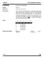
Table of Contents
1
Standard Instruction Set - - - - - - - - - - - - - - - - - - - 5
1.1
Addressing modes - - - - - - - - - - - - - - - - - - - - - - - 5
1.1.1
1.1.2
1.1.3
1.1.4
1.1.5
1.1.6
Short adressing modes - - - - Long addressing mode - - - - DPP override mechanism - - - Indirect addressing modes - - Constants - - - - - - - - - - Branch target addressing modes
-
-
-
-
-
-
-
-
-
-
-
-
-
-
-
-
-
-
-
-5
-6
-8
-9
10
11
1.2
Instruction execution times - - - - - - - - - - - - - - - - - - 12
1.2.1
1.2.2
1.2.3
Definition of measurement units - - - - - - - - - - - - - - - - - - - - 12
Minimum state times - - - - - - - - - - - - - - - - - - - - - - - - - 14
Additional state times - - - - - - - - - - - - - - - - - - - - - - - - - 15
1.3
Instruction set summary - - - - - - - - - - - - - - - - - - - 17
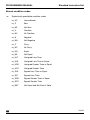
1.4
Instruction set ordered by functional group - - - - - - - - - - 21
1.5
Instruction set ordered by opcodes - - - - - - - - - - - - - - 37
1.6
Instruction conventions - - - - - - - - - - - - - - - - - - - - 45
1.6.1
1.6.2
1.6.3
1.6.4
1.6.5
1.6.6
1.6.7
1.6.8
Instruction name Syntax - - - - - Operation - - - Data types - - - Description - - - Condition code - Flags - - - - - - Addressing modes
1.7
ATOMIC and EXTended instructions - - - - - - - - - - - - - 53
1.8
Instruction descriptions - - - - - - - - - - - - - - - - - - - - 54
2
MAC Instruction set - - - - - - - - - - - - - - - - - - - - - 139
2.1
Addressing modes - - - - - - - - - - - - - - - - - - - - - - 139
2.2
MAC instruction execution time - - - - - - - - - - - - - - - - 140
2.3
MAC instruction set summary - - - - - - - - - - - - - - - - - 141
2.4
MAC instruction conventions - - - - - - - - - - - - - - - - - 144
2.4.1
2.4.2
2.4.3
Operands - - - - - - - - - - - - - - - - - - - - - - - - - - - - - 144
Operations - - - - - - - - - - - - - - - - - - - - - - - - - - - - - 144
Abbreviations - - - - - - - - - - - - - - - - - - - - - - - - - - - - 145
2/197
-
-
-
-
-
-
-
-
-
-
-
-
-
-
-
-
-
-
-
-
-
-
-
-
-
-
46
46
46
48
48
48
50
51
PROGRAMMING MANUAL
2.4.4
2.4.5
2.4.6
2.4.7
2.4.8
Data addressing modes - Instruction format - - - - - Flag states - - - - - - - - Repeated instruction syntax
Shift value - - - - - - - - -
-
-
-
-
-
-
-
-
-
-
-
-
-
-
-
-
-
-
-
-
145
145
146
146
147
2.5
MAC instruction descriptions - - - - - - - - - - - - - - - - - 147
3
Revision History
- - - - - - - - - - - - - - - - - - - - - - 195
3/197
PROGRAMMING MANUAL
Introduction
This programming manual details the instruction set for the ST10 family of products. The
manual is arranged in two sections. Section 1 details the standard instruction set and
includes all of the basic instructions. Section 2 details the extension to the instruction set
provided by the MAC. The MAC instructions are only available to devices containing the
MAC, refer to the datasheet for device-specific information.
In the standard instruction set, addressing modes, instruction execution times, minimum
state times and the causes of additional state times are defined. Cross reference tables of
instruction mnemonics, hexadecimal opcode, address modes and number of bytes, are
provided for the optimization of instruction sequences. Instruction set tables ordered by
functional group, can be used to identify the best instruction for a given application.
Instruction set tables ordered by hexadecimal opcode can be used to identify specific
instructions when reading executable code i.e. during the de-bugging phase. Finally, each
instruction is described individually on a page of standard format, using the conventions
defined in this manual. For ease of use, the instructions are listed alphabetically.
The MAC instruction set is divided into its 5 functional groups: Multiply and
Multiply-Accumulate, 32-Bit Arithmetic, Shift, Compare and Transfer Instructions. Two new
addressing modes supply the MAC with up to 2 new operands per instruction. Cross
reference tables of MAC instruction mnemonics by address mode, and MAC instruction
mnemonic by functional code can be used for quick reference. As for the standard instruction
set, each instruction has been described individually in a standard format according to
defined conventions. For convenience, the instructions are described in alphabetical order.
4/197
PROGRAMMING MANUAL
Standard Instruction Set
1
Standard Instruction Set
1.1
Addressing modes
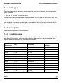
1.1.1 Short adressing modes
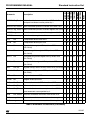
The ST10 family of devices use several powerful addressing modes for access to word, byte
and bit data. This section describes short, long and indirect address modes, constants and
branch target addressing modes.
Short addressing modes use an implicit base offset address to specify the 24-bit physical
address.
Short addressing modes give access to the GPR, SFR or bit-addressable memory space
PhysicalAddress = BaseAddress + ShortAddress
Note:
= 1 for byte GPRs, = 2 for word GPRs.
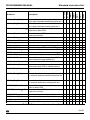
Mnemo Physical Address
Short Address Range Scope of Access
Rw
(CP)
+ 2*Rw
Rw
= 0...15
GPRs
(Word) 16 values
Rb
(CP)
+ 1*Rb
Rb
= 0...15
GPRs
(Byte) 16 values
reg
00’FE00h + 2*reg
reg
= 00h...EFh
SFRs
(Word, Low byte)
00’F000h
+ 2*reg
reg
= 00h...EFh
ESFRs
(Word, Low byte)
(CP)
+ 2*(reg^0Fh)
reg
= F0h...FFh
GPRs
(Word) 16 values
(CP)
+ 1*(reg^0Fh)
reg
= F0h...FFh
GPRs
(Bytes) 16 values
bitoff
= 00h...7Fh
RAM
Bit word offset 128 values
00’FF00h + 2*(bitoff^FFh) bitoff
= 80h...EFh
SFR
Bit word offset 128 values
(CP)
= F0h...FFh
GPR
Bit word offset 16 values
Any single bit
bitoff
bitaddr
00’FD00h + 2*bitoff
+ 2*(bitoff^0Fh) bitoff
Word offset as with bitoff.
bitoff
= 00h...FFh
Immediate bit position.
bitpos
= 0...15
Table 1 Short addressing mode summary
5/197
Standard Instruction Set
PROGRAMMING MANUAL
Rw, Rb:
Specifies direct access to any GPR in the currently active context (register bank). Both
'Rw' and 'Rb' require four bits in the instruction format. The base address of the current
register bank is determined by the content of register CP. 'Rw' specifies a 4-bit word GPR
address relative to the base address (CP), while 'Rb' specifies a 4 bit byte GPR address
relative to the base address (CP).
reg:
Specifies direct access to any (E)SFR or GPR in the currently active context (register
bank). 'reg' requires eight bits in the instruction format. Short 'reg' addresses from 00h to
EFh always specify (E)SFRs. In this case, the factor '' equals 2 and the base address is
00’F000h for the standard SFR area, or 00’FE00h for the extended ESFR area. ‘reg’
accesses to the ESFR area require a preceding EXT*R instruction to switch the base
address. Depending on the opcode of an instruction, either the total word (for word operations), or the low byte (for byte operations) of an SFR can be addressed via 'reg'. Note that
the high byte of an SFR cannot be accessed by the 'reg' addressing mode. Short 'reg'
addresses from F0h to FFh always specify GPRs. In this case, only the lower four bits of
'reg' are significant for physical address generation, therefore it can be regarded as identical to the address generation described for the 'Rb' and 'Rw' addressing modes.
bitoff:
Specifies direct access to any word in the bit-addressable memory space. 'bitoff' requires
eight bits in the instruction format. Depending on the specified 'bitoff' range, different base
addresses are used to generate physical addresses: Short 'bitoff' addresses from 00h to
7Fh use 00’FD00h as a base address, therefore they specify the 128 highest internal RAM
word locations (00’FD00h to 00’FDFEh). Short 'bitoff' addresses from 80h to EFh use
00’FF00h as a base address to specify the highest internal SFR word locations (00’FF00h
to 00’FFDEh) or use 00’F100h as a base address to specify the highest internal ESFR
word locations (00’F100h to 00’F1DEh). ‘bitoff’ accesses to the ESFR area require a preceding EXT*R instruction to switch the base address. For short 'bitoff' addresses from F0h
to FFh, only the lowest four bits and the contents of the CP register are used to generate
the physical address of the selected word GPR.
bitaddr:
Any bit address is specified by a word address within the bit-addressable memory space
(see 'bitoff'), and by a bit position ('bitpos') within that word. Thus, 'bitaddr' requires twelve
bits in the instruction format.
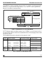
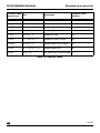
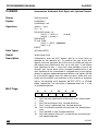
1.1.2 Long addressing mode
Long addressing mode uses one of the four DPP registers to specify a physical 18-bit or
24-bit address. Any word or byte data within the entire address space can be accessed in
this mode. All devices support an override mechanism for the DPP addressing scheme (see
section 1.1.3).
Note
6/197
Word accesses on odd byte addresses are not executed, but rather trigger a
hardware trap. After reset, the DPP registers are initialized so that all long
addresses are directly mapped onto the identical physical addresses, within
segment 0.
PROGRAMMING MANUAL
Standard Instruction Set
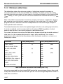
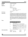
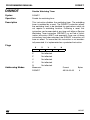
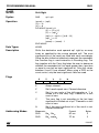
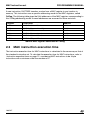
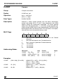
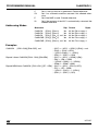
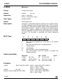
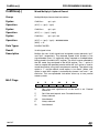
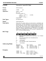
Long addresses (16-bit) are treated in two parts. Bits 13...0 specify a 14-bit data page offset,
and bits 15...14 specify the Data Page Pointer (1 of 4). The DPP is used to generate the
physical 24-bit address (see figure below).
16-bit Long Address
15
selects Data Page Pointer
9
DPP0
DPP1
DPP2
DPP3
23
14 13
0
0
14-bit page offset
0
14 13
24-bit Physical Address
Figure 1 Interpretation of a 16-bit long address
All ST10 devices support an address space of up to 16 MByte, so only the lower ten bits of
the selected DPP register content are concatenated with the 14-bit data page offset to build
the physical address.
The long addressing mode is referred to by the mnemonic “mem”.
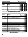
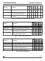
Mnemo
Physical Address
Long Address Range
Scope of Access
mem
(DPP0)
|| mem^3FFFh
0000h...3FFFh
Any Word or Byte
(DPP1)
|| mem^3FFFh
4000h...7FFFh
(DPP2)
|| mem^3FFFh
8000h...BFFFh
(DPP3)
|| mem^3FFFh
C000h...FFFFh
mem
pag
|| mem^3FFFh
0000h...FFFFh (14-bit)
Any Word or Byte
mem
seg
|| mem
0000h...FFFFh (16-bit)
Any Word or Byte
Table 2 Summary of long address modes
7/197
Standard Instruction Set
PROGRAMMING MANUAL
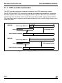
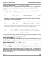
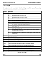
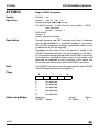
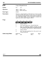
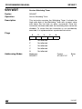
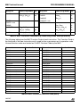
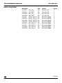
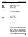
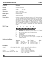
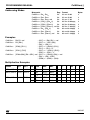
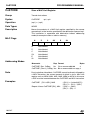
1.1.3 DPP override mechanism
The DPP override mechanism temporarily bypasses the DPP addressing scheme.
The EXTP(R) and EXTS(R) instructions override this addressing mechanism. Instruction
EXTP(R) replaces the content of the respective DPP register, while instruction EXTS(R)
concatenates the complete 16-bit long address with the specified segment base address.
The overriding page or segment may be specified directly as a constant (#pag, #seg) or by a
word GPR (Rw).
15 14 13
EXTP(R):
0
16-bit Long Address
#pag
14-bit page offset
24-bit Physical Address
15
EXTS(R):
0
16-bit Long Address
#seg
16-bit segment offset
24-bit Physical Address
Figure 2 Overriding the DPP mechanism
8/197
PROGRAMMING MANUAL
Standard Instruction Set
1.1.4 Indirect addressing modes
Indirect addressing modes can be considered as a combination of short and long
addressing modes. In this mode, long 16-bit addresses are specified indirectly by the
contents of a word GPR, which is specified directly by a short 4-bit address ('Rw'=0 to 15).
Some indirect addressing modes add a constant value to the GPR contents before the long
16-bit address is calculated. Other indirect addressing modes allow decrementing or
incrementing of the indirect address pointers (GPR content) by 2 or 1 (referring to words or
bytes).
In each case, one of the four DPP registers is used to specify the physical 18-bit or 24-bit
addresses. Any word or byte data within the entire memory space can be addressed
indirectly. Note that EXTP(R) and EXTS(R) instructions override the DPP mechanism.
Instructions using the lowest four word GPRs (R3...R0) as indirect address pointers are
specified by short 2-bit addresses.
Word accesses on odd byte addresses are not executed, but rather trigger a hardware trap.
After reset, the DPP registers are initialized in a way that all indirect long addresses are
directly mapped onto the identical physical addresses.
Physical addresses are generated from indirect address pointers by the following algorithm:
1
Calculate the physical address of the word GPR which is used as indirect address
pointer, by using the specified short address ('Rw') and the current register bank base
address (CP).
GPRAddress = CP + 2 ShortAddress – ; optionalstep!
2
Pre-decremented indirect address pointers (‘-Rw’) are decremented by a
data-type-dependent value ( = 1 for byte operations, = 2 for word operations),
before the long 16-bit address is generated:
GPRAddress = GPRAddress – ; optionalstep!
3
Calculate the long 16-bit address by adding a constant value (if selected) to the content
of the indirect address pointer:
Long Address = (GPR Pointer) + Constant
4
Calculate the physical 18-bit or 24-bit address using the resulting long address and the
corresponding DPP register content (see long 'mem' addressing modes).
Physical Address = (DPPi) + Page offset
5
Post-Incremented indirect address pointers (‘Rw+’) are incremented by a
data-type-dependent value ( = 1 for byte operations, = 2 for word operations):
GPRPointer = GPRPointer + ; optionalstep!
9/197
Standard Instruction Set
PROGRAMMING MANUAL
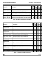
The following indirect addressing modes are provided:
Mnemonic
Notes
[Rw]
Most instructions accept any GPR (R15...R0) as indirect address pointer.
Some instructions, however, only accept the lower four GPRs (R3...R0).
[Rw+]
The specified indirect address pointer is automatically incremented by 2 or 1 (for
word or byte data operations) after the access.
[-Rw]
The specified indirect address pointer is automatically decremented by 2 or 1 (for
word or byte data operations) before the access.
[Rw+#data16]
A 16-bit constant and the contents of the indirect address pointer are added
before the long 16-bit address is calculated.
Table 3 Table of indirect address modes
1.1.5 Constants
The ST10 Family instruction set supports the use of wordwide or bytewide immediate
constants. For optimum utilization of the available code storage, these constants are
represented in the instruction formats by either 3, 4, 8 or 16 bits. Therefore, short constants
are always zero-extended, while long constants can be truncated to match the data format
required for the operation (see table below):
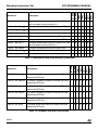
Mnemonic
Word operation
Byte operation
#data3
0000h + data3
00h + data3
#data4
0000h + data4
00h + data4
#data8
0000h + data8
data8
#data16
data16
data16 ^ FFh
#mask
0000h + mask
mask
Table 4 Table of constants
Note
10/197
Immediate constants are always signified by a leading number sign “#”.
PROGRAMMING MANUAL
Standard Instruction Set
1.1.6 Branch target addressing modes
Jump and Call instructions use different addressing modes to specify the target address and
segment. Relative, absolute and indirect modes can be used to update the Instruction
Pointer register (IP), while the Code Segment Pointer register (CSP) can only be updated
with an absolute value. A special mode is provided to address the interrupt and trap jump
vector table situated in the lowest portion of code segment 0.
Mnemo
Target Address
Target Segment
Valid Address Range
caddr
(IP)
= caddr
-
caddr
= 0000h...FFFEh
rel
(IP)
= (IP) + 2*rel
-
rel
= 00h...7Fh
(IP)
= (IP) + 2*(~rel+1)
-
rel
= 80h...FFh
[Rw]
(IP)
= ((CP) + 2*Rw)
-
Rw
= 0...15
seg
-
(CSP) = seg
seg
= 0...255
#trap7
(IP)
(CSP) = 0000h
trap7
= 00h...7Fh
= 0000h + 4*trap7
Table 5 Branch target address summary
caddr:
Specifies an absolute 16-bit code address within the current segment. Branches MAY
NOT be taken to odd code addresses. Therefore, the least significant bit of 'caddr' must
always contain a '0', otherwise a hardware trap would occur.
rel:
Represents an 8-bit signed word offset address relative to the current Instruction Pointer
contents which points to the instruction after the branch instruction. Depending on the offset address range, either forward ('rel'= 00h to 7Fh) or backward ('rel'= 80h to FFh)
branches are possible. The branch instruction itself is repeatedly executed, when 'rel' = '-1'
(FFh) for a word-sized branch instruction, or 'rel' = '-2' (FEh) for a double-word-sized
branch instruction.
[Rw]:
The 16-bit branch target instruction address is determined indirectly by the content of a
word GPR. In contrast to indirect data addresses, indirectly specified code addresses are
NOT calculated by additional pointer registers (e.g. DPP registers). Branches MAY NOT
be taken to odd code addresses. Therefore, to prevent a hardware trap, the least significant bit of the address pointer GPR must always contain a '0.
seg:
Specifies an absolute code segment number. All devices support 256 different code segments, so only the eight lower bits of the 'seg' operand value are used for updating the
CSP register.
#trap7:
Specifies a particular interrupt or trap number for branching to the corresponding interrupt
or trap service routine by a jump vector table. Trap numbers from 00h to 7Fh can be specified, which allows access to any double word code location within the address range
00’0000h...00’01FCh in code segment 0 (i.e. the interrupt jump vector table). For further
information on the relation between trap numbers and interrupt or trap sources, refer to the
device user manual section on “Interrupt and Trap Functions”.
11/197
Standard Instruction Set
1.2
PROGRAMMING MANUAL
Instruction execution times
The instruction execution time depends on where the instruction is fetched from, and where
the operands are read from or written to. The fastest processing mode is to execute a
program fetched from the internal ROM. In this case most of the instructions can be
processed in just one machine cycle.
All external memory accesses are performed by the on-chip External Bus Controller (EBC)
which works in parallel with the CPU. Instructions from external memory cannot be
processed as fast as instructions from the internal ROM, because it is necessary to perform
data transfers sequentially via the external interface. In contrast to internal ROM program
execution, the time required to process an external program additionally depends on the
length of the instructions and operands, on the selected bus mode, and on the duration of an
external memory cycle.
Processing a program from the internal RAM space is not as fast as execution from the
internal ROM area, but it is flexible (i.e. for loading temporary programs into the internal RAM
via the chip's serial interface, or end-of-line programming via the bootstrap loader).
The following description evaluates the minimum and maximum program execution times.
which is sufficient for most requirements. For an exact determination of the instructions'
state times, the facilities provided by simulators or emulators should be used.
This section defines measurement units, summarizes the minimum (standard) state times of
the 16-bit microcontroller instructions, and describes the exceptions from the standard
timing.
1.2.1 Definition of measurement units
The following measurement units are used to define instruction processing times:
[fCPU]:
CPU operating frequency (may vary from 1 MHz to 50 MHz).
[State]:
One state time is specified by one CPU clock period. Therefore, one State is used as the
basic time unit, because it represents the shortest period of time which has to be considered
for instruction timing evaluations.
1 [State]
12/197
= 1/fCPU[s]
; for fCPU = variable
= 50[ns]
; for fCPU = 20 MHz
PROGRAMMING MANUAL
Standard Instruction Set
[fCPU]:
CPU operating frequency (may vary from 1 MHz to 50 MHz).
[ACT]:
ALE (Address Latch Enable) Cycle Time specifies the time required to perform one external
memory access. One ALE Cycle Time consists of either two (for demultiplexed external bus
modes) or three (for multiplexed external bus modes) state times plus a number of state
times, which is determined by the number of waitstates programmed in the MCTC (Memory
Cycle Time Control) and MTTC (Memory Tristate Time Control) bit fields of the SYSCON/
BUSCONx registers.
For demultiplexed external bus modes:
1*ACT
= (2 + (15 – MCTC) + (1 – MTTC)) * States
= 100 n... 900 ns ; for fCPU = 20 MHz
For multiplexed external bus modes:
1*ACT
= (3 + (15 – MCTC) + (1 – MTTC)) * States
= 150 ns ... 950 ns ; for fCPU = 20 MHz
Ttot
The total time (Ttot) taken to process a particular part of a program can be calculated by the
sum of the single instruction processing times (TIn) of the considered instructions plus an
offset value of 6 state times which takes into account the solitary filling of the pipeline:
Ttot
TIn
=TI1 + TI2 + ... + TIn + 6 * States
The time (TIn) taken to process a single instruction, consists of a minimum number (TImin)
plus an additional number (TIadd) of instruction state times and/or ALE Cycle Times:
TIn
=TImin + TIadd
13/197
Standard Instruction Set
PROGRAMMING MANUAL
1.2.2 Minimum state times
The table below shows the minimum number of state times required to process an
instruction fetched from the internal ROM (TImin (ROM)). This table can also be used to
calculate the minimum number of state times for instructions fetched from the internal RAM
(TImin (RAM)), or ALE Cycle Times for instructions fetched from the external memory (TImin
(ext)).
Most of the 16-bit microcontroller instructions (except some branch, multiplication, division
and a special move instructions) require a minimum of two state times. For internal ROM
program execution, execution time has no dependence on instruction length, except for
some special branch situations.
To evaluate the execution time for the injected target instruction of a cache jump instruction,
it can be considered as if it was executed from the internal ROM, regardless of which
memory area the rest of the current program is really fetched from.
For some of the branch instructions the table below represents both the standard number of
state times (i.e. the corresponding branch is taken) and an additional TImin value in
parentheses, which refers to the case where, either the branch condition is not met, or a
cache jump is taken.
Instruction
TImin (ROM) [States]
TImin (ROM) (20MHz CPU clk)
CALLI, CALLA
4
200
CALLS, CALLR, PCALL
4
JB, JBC, JNB, JNBS
4
JMPS
4
JMPA, JMPI, JMPR
4
MUL, MULU
10
500
DIV, DIVL, DIVU, DIVLU
20
1000
MOV[B] Rn, [Rm + #data16]
4
200
RET, RETI, RETP, RETS
4
200
TRAP
4
200
All other instructions
2
100
(2)
(100)
200
(2)
200
(100)
200
(2)
200
(100)
Table 6 Minimum instruction state times [Unit = ns]
Instructions executed from the internal RAM require the same minimum time as they would
if they were fetched from the internal ROM, plus an instruction-length dependent number of
state times, as follows:
14/197
PROGRAMMING MANUAL
Standard Instruction Set
•
For 2-byte instructions: TImin(RAM) = TImin(ROM) + 4 * States
•
For 4-byte instructions: TImin(RAM) = TImin(ROM) + 6 * States
Unlike internal ROM program execution, the minimum time TImin(ext) to process an external
instruction also depends on instruction length. TImin(ext) is either 1 ALE Cycle Time for most
of the 2-byte instructions, or 2 ALE Cycle Times for most of the 4-byte instructions. The
following formula represents the minimum execution time of instructions fetched from an
external memory via a 16-bit wide data bus:
•
For 2-byte instructions: TImin(ext) = 1*ACT + (TImin(ROM) - 2) * States
•
For 4-byte instructions: TImin(ext) = 2*ACTs + (TImin(ROM) - 2) * States
Note
For instructions fetched from an external memory via an 8-bit wide data bus, the
minimum number of required ALE Cycle Times is twice the number for those of a
16-bit wide bus.
1.2.3 Additional state times
Some operand accesses can extend the execution time of an instruction TIn. Since the
additional time TIadd is generally caused by internal instruction pipelining, it may be possible
to minimize the effect by rearranging the instruction sequences. Simulators and emulators
offer a high level of programmer support for program optimization.
The following operands require additional state times:
Internal ROM operand reads:TIadd = 2 * States
Both byte and word operand reads always require 2 additional state times.
Internal RAM operand reads via indirect addressing modes: TIadd = 0 or 1 * State
Reading a GPR or any other directly addressed operand within the internal RAM space does
NOT cause additional state times. However, reading an indirectly addressed internal RAM
operand will extend the processing time by 1 state time, if the preceding instruction
auto-increments or auto-decrements a GPR, as shown in the following example:
In
: MOV R1, [R0+]
; auto-increment R0
In+1
: MOV [R3], [R2]
; if R2 points into the internal RAM space:
; TIadd = 1 * State
In this case, the additional time can be avoided by putting another suitable instruction before
the instruction In+1 indirectly reading the internal RAM.
15/197
Standard Instruction Set
PROGRAMMING MANUAL
Internal SFR operand reads: TIadd = 0, 1 * State or 2 * States
SFR read accesses do NOT usually require additional processing time. In some rare cases,
however, either one or two additional state times will be caused by particular SFR
operations:
•
•
•
Reading an SFR immediately after an instruction, which writes to the internal SFR
space, as shown in the following example:
In
: MOV
T0, #1000h
; write to Timer 0
In+1
: ADD
R3, T1
; read from Timer 1: TIadd = 1
*
State
Reading the PSW register immediately after an instruction which implicitly updates the
flags as shown in the following example:
In
: ADD
In+1
: BAND
R0, #1000h
C, Z
; implicit modification of PSW flags
; read from PSW: TIadd = 2
*
States
Implicitly incrementing or decrementing the SP register immediately after an instruction
which explicitly writes to the SP register, as shown in the following example:
In
: MOV
SP, #0FB00h ; explicit update of the stack pointer
In+1
: SCXT R1, #1000h
; implicit decrement of the stack pointer:
; TIadd = 2
*
States
In each of these above cases, the extra state times can be avoided by putting other suitable
instructions before the instruction In+1 reading the SFR.
External operand reads: TIadd = 1 * ACT
Any external operand reading via a 16-bit wide data bus requires one additional ALE Cycle
Time. Reading word operands via an 8-bit wide data bus takes twice as much time (2 ALE
Cycle Times) as the reading of byte operands.
External operand writes: TIadd = 0 * State ... 1 * ACT
Writing an external operand via a 16-bit wide data bus takes one additional ALE Cycle Time.
For timing calculations of external program parts, this extra time must always be considered.
The value of TIadd which must be considered for timing evaluations of internal program
parts, may fluctuate between 0 state times and 1 ALE Cycle Time. This is because external
writes are normally performed in parallel to other CPU operations. Thus, TIadd could already
have been considered in the standard processing time of another instruction. Writing a word
operand via an 8-bit wide data bus requires twice as much time (2 ALE Cycle Times) as the
writing of a byte operand.
16/197
PROGRAMMING MANUAL
Standard Instruction Set
Jumps into the internal ROM space: TIadd = 0 or 2 * States
The minimum time of 4 state times for standard jumps into the internal ROM space will be
extended by 2 additional state times, if the branch target instruction is a double word
instruction at a non-aligned double word location (xxx2h, xxx6h, xxxAh, xxxEh), as shown in
the following example:
label
: ....
; any non-aligned double word instruction
....
: ....
In+1
: JMPA cc_UC, label
; (e.g. at location 0FFEh)
; if a standard branch is taken:
; TIadd = 2
*
States (TIn = 6
*
States)
A cache jump, which normally requires just 2 state times, will be extended by 2 additional
state times, if both the cached jump target instruction and the following instruction are
non-aligned double word instructions, as shown in the following example:
label
: ....
; any non-aligned double word instruction
; (e.g. at location 12FAh)
In+1
....
:
; any non-aligned double word instruction
In+1
: JMPR cc_UC, label
; (e.g. at location 12FEh)
; provided that a cache jump is taken:
; TIadd = 2
*
States (TIn = 4
*
States)
If necessary, these extra state times can be avoided by allocating double word jump target
instructions to aligned double word addresses (xxx0h, xxx4h, xxx8h, xxxCh).
Testing Branch Conditions: TIadd = 0 or 1 * States
NO extra time is usually required for a conditional branch instructions to decide whether a
branch condition is met or not. However, an additional state time is required if the preceding
instruction writes to the PSW register, as shown in the following example:
In
: BSET USR0
; implicit modification of PSW flags
In+1
: JMPR cc_Z, label ; test condition flag in PSW: TIadd= 1
*
State
In this case, the extra state time can be intercepted by putting another suitable instruction
before the conditional branch instruction.
1.3
Instruction set summary
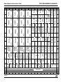
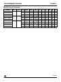
The following table lists the instruction mnemonic by hex-code with operand.
Table 7 Instruction mnemonic by hex-code with operand
17/197
ROL
Lo 0x
Hi
18/197
1x
SUBB
BCMP
2x
3x
4x
5x
BITadd, BITadd
BXOR
Rwn
DIVLU
Rwn
SHR
Rwn, #d4
6x
7x
8x
JBC
9x
Ax
Bx
Cx
Dx
Ex
Fx
SEG, CADDR
-
x8
-
[Rwn], [Rwm+]
-
MOV
x6
MEM, REG
MOVB
MOVBS
MOV
REG,MEM
x5
REG, Data#16
MOV MOVB
MEM,REG
MOVB
[Rwm+#d16],Rwn
CoMOV
MOV
REG,CADDR
PCALL
MOVBS
MOV
MOV
MOVBS
Rwn, Rwm
Rwn, #data4
MOVB
Rwn, #data4
MOVB
ATOMIC
/EXTR
#data2
-
MOVBZ
REG, MEM
CMPD2
CPLB
CMPD2
MOVBZ
Rwn, #d4
Rwn
Rwn, MEM
REG, MEM
MOVB
-
[IDXi],[Rwm]
Rwn,[Rwm+#d16]
MOVB
[Rwm+#d16],Rwn
MOV
CoSTORE
[Rwn],CoREG
Rwn,[Rwm+#d16]
MOV
[Rwm+#d16],Rwn
Rwn,CoREG
CoSTORE
Fx
xA
RETI
JMPS
CC, CADDR
REG
MOVB
SCXT
REG,#d16
MOVBZ
MOVB
[Rwn],MEM
Ex
xB
POP
REG
JMPA
SEG, CADDR
RETP
MOV EXTP(R)/
EXTS(R)
[Rwn+], [Rwm] #pag,#data2
MOVB
[Rwn], [Rwm]
SCXT
CMPD2
EINIT
CMPI2
CMPD1
CPL
NEGB
CMPI2
Rwn, #d4
Rwn
CMPD1
Rwn, MEM
Dx
PUSH
CALLS
-
MOV
[Rwm], Rwn
MOVB
Rwn,#d16
Rwn,Rwm
CoXXX
CoXXX
[IDXi],[Rwm]
OR
CMPI1
Cx
Rwm, #d2
RETS
EXTP(R)/
EXTS(R)
SRST
MOV
Rwn, [Rwm]
MOVB
MOVB
MEM,[Rwn]
MOV
Rwn,[Rwm]
NEG
OR ORB
CMPI
Bx
CC, CADDR
JNBS
CALLA
REL
RET
NOP
BITadd, REL
Rwn, #d4
CALLR
CMPI2
CMPD1 DISWDT
-
[Rwn],MEM
CoXXX
OR ORB
Ax
ASHR
SRVWDT
MOV
Rwn,#d16
MOV
9x
Rwn, Rwm cc, [Rw ]
n
Rwn, [Rwm+]
MOVB
JNB
#trap
CALLI
ASHR
PWRDN
MOV
cc, [Rwn]
MOVB
[-Rwm], Rwn
-
OR ORB
CMPI1
Rwn, Rwm
8x
BITadd, REL
IDLE
OR ORB
MOV
TRAP
MOVB
JMPI
JB
BITadd, BITadd ORB
REG, MEM
AND
AND ANDB
AND ANDB
7x
-
MEM, REG
XOR
XOR XORB
XOR XORB
6x
-
REG, #data16
AND ANDB
XOR XORB
MEM, REG
CMP
Rwn, Rwm
SUBC
CMP CMPB
Rwn, Rwm
SUBC SUBCB
REG, MEM
- CMPB
SUBC SUBCB
REG, MEM
5x
Rwn,[Rwi]
Rwn,[Rwi+]
Rwn, #data3
AND ANDB
Rwn, Rwm
XOR XORB
DIVL
SHR
CMP -
SUBC SUBCB
REG, #data16
ANDB
BAND
Rwn
CMP CMPB
Rwn,[Rwi]
Rwn,[Rwi+]
Rwn, #data3
CMPB
BITadd, BITadd XORB
DIVU
BOR
BITadd, BITadd
SHL
Rwn
BMOV
BITadd, BITadd SUBCB SUBC SUBCB
MEM, REG
SUB
SUB SUBB
REG, #data16
ADDC
ADDC ADDCB
SUB SUBB
ADD
ADDC ADDCB
Rwn, Rwm
x0
4x
Rwn, #d4
Rwn, Rwm
DIV
BMOVN
x1
ADD ADDB
SUB SUBB
REG, MEM
x2
3x
SHL
Rwn, #d4
-
x3
ADD ADDB
ADDC ADDCB
MEM, REG
x4
2x
ROR
Rwn,[Rwi]
Rwn,[Rwi+]
Rwn, #data3
SUB SUBB
ADDCB ADDC ADDCB
BFLDH
MULU
PRIOR
x5
ADD ADDB
1x
Rwn, Rwm Rwn, Rwm BITadd, BITadd
x6
REG, #data16
ROR
BITOFF,
MASK, #data3
Rwn, Rwm
x7
ADD ADDB
x8
Rwn,[Rwi]
Rwn,[Rwi+]
Rwn, #data3
ADDB
x9
Rwn, #d4
BFLDL
xA
MUL
xB
Hi 0x
Lo
ROL
Rwn, Rwm
xF xE xD xC
Standard Instruction Set
PROGRAMMING MANUAL
Hi
Lo
x0
x1
x2
x3
x4
x7
x9
xC
JMPR
cc, rel
xD
BCLR
BITaddrQ.q
xE
BSET
BITaddrQ.q
xF
Lo
Hi
PROGRAMMING MANUAL
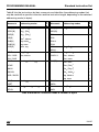
Standard Instruction Set
Addressing modes
ADD[B]
Rwn1, Rwm 1
ADDC[B]
Rwn1, [Rwi]
AND[B]
Mnemonic
Addressing modes
Bytes
Mnemonic
Bytes
Table 8 lists the instructions by their mnemonic and identifies the addressing modes that
may be used with a specific instruction and the instruction length, depending on the selected
addressing mode (in bytes).
2
CPL[B]
Rwn1
2
2
NEG[B]
Rwn
2
Rwn, Rwm
2
Rwn
1,
[Rwi+]
2
DIV
OR[B]
Rwn
1,
#data3
2
DIVL
SUB[B]
reg, #data16
4
DIVLU
SUBC[B]
reg, mem
4
DIVU
XOR[B]
mem, reg
4
MUL
MULU
ASHR
Rwn, Rwm
2
CMPD1/2
Rwn, #data4
2
ROL / ROR
Rwn, #data4
2
CMPI1/2
Rwn, #data16
4
Rwn, mem
4
bitaddrZ.z, bitaddrQ.q
4
CMP[B]
SHL / SHR
BAND
Rwn, Rwm
1
BCMP
Rwn, [Rwi] 1
2
BMOV
Rwn, [Rwi+]1
2
1
2
BMOVN
Rwn, #data3
BOR / BXOR
reg, #data16
4
reg, mem
4
cc, caddr
4
cc, [Rwn]
2
BCLR
bitaddrQ.q,
2
BSET
BFLDH
BFLDL
CALLA
JMPA
bitoffQ, #mask8, #data8
4
CALLI
JMPI
Table 8 Mnemonic vs address mode & number of bytes
19/197
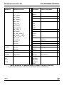
Mnemonic
Addressing modes
Bytes
PROGRAMMING MANUAL
Bytes
Standard Instruction Set
2
CALLS
seg, caddr
4
Rwn1, #data4
2
JMPS
Rwn1, [Rwm]
2
CALLR
rel
2
Rwn1, [Rwm+]
2
JMPR
cc, rel
2
[Rwm], Rwn1
2
JB
bitaddrQ.q, rel
4
[-Rwm], Rwn 1
2
JBC
[Rwn], [Rwm]
2
JNB
[Rwn+], [Rwm]
2
JNBS
[Rwn], [Rwm+]
2
PCALL
reg, caddr
4
reg, #data16
4
POP
reg
2
Rwn, [Rwm+#data16]1
4
PUSH
[Rwm+#data16], Rwn 1
4
RETP
[Rwn], mem
4
SCXT
reg, #data16
4
mem, [Rwn]
4
reg, mem
4
reg, mem
4
PRIOR
Rwn, Rwm
2
mem, reg
4
MOVBS
Rwn, Rbm
2
TRAP
#trap7
2
MOVBZ
reg, mem
4
ATOMIC
#data2
2
mem, reg
4
EXTR
EXTS
Rwm, #data2
2
EXTP
Rwm, #data2
2
EXTSR
#seg, #data2
4
EXTPR
#pag, #data2
4
NOP
-
2
SRST/IDLE
-
4
Mnemonic
Addressing modes
MOV[B]
Rwn1, Rwm1
RET
PWRDN
RETI
SRVWDT
RETS
DISWDT
EINIT
Table 8 Mnemonic vs address mode & number of bytes (Continued)
1. Byte oriented instructions (suffix ‘B’) use Rb instead of Rw (not with [Rwi]!).
20/197
PROGRAMMING MANUAL
1.4
Standard Instruction Set
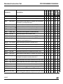
Instruction set ordered by functional group
The minimum number of state times required for instruction execution are given for the
following configurations: internal ROM, internal RAM, external memory with a 16-bit
demultiplexed and multiplexed bus or an 8-bit demultiplexed and multiplexed bus. These
state time figures do not take into account possible wait states on external busses or
possible additional state times induced by operand fetches. The following notes apply to this
summary:
Data addressing modes
Rw:
Word GPR (R0, R1, … , R15)
Rb:
Byte GPR (RL0, RH0, …, RL7, RH7)
reg:
SFR or GPR (in case of a byte operation on an SFR, only the low byte can be
accessed via ‘reg’)
mem:
Direct word or byte memory location
[…]:
Indirect word or byte memory location. (Any word GPR can be used as indirect
address pointer, except for the arithmetic, logical and compare instructions,
where only R0 to R3 are allowed)
bitaddr:
Direct bit in the bit-addressable memory area
bitoff:
Direct word in the bit-addressable memory area
#datax:
Immediate constant (the number of significant bits that can be user-specified is
given by the appendix “x”).
#mask8:
Immediate 8-bit mask used for bit-field modifications
Multiply and divide operations
The MDL and MDH registers are implicit source and/or destination operands of the multiply
and divide instructions.
21/197
Standard Instruction Set
PROGRAMMING MANUAL
Branch target addressing modes
caddr:
Direct 16-bit jump target address (Updates the Instruction Pointer)
seg:
Direct 8-bit segment address (Updates the Code Segment Pointer)
rel:
Signed 8-bit jump target word offset address relative to the Instruction Pointer of
the following instruction
#trap7:
Immediate 7-bit trap or interrupt number.
Extension operations
The EXT* instructions override the standard DPP addressing scheme:
#pag:
Immediate 10-bit page address.
#seg:
Immediate 8-bit segment address.
22/197
PROGRAMMING MANUAL
Standard Instruction Set
Branch condition codes
cc:
Symbolically specifiable condition codes
cc_UC
Unconditional
cc_Z
Zero
cc_NZ
Not Zero
cc_V
Overflow
cc_NV
No Overflow
cc_N
Negative
cc_NN
Not Negative
cc_C
Carry
cc_NC
No Carry
cc_EQ
Equal
cc_NE
Not Equal
cc_ULT
Unsigned Less Than
cc_ULE
Unsigned Less Than or Equal
cc_UGE
Unsigned Greater Than or Equal
cc_UGT
Unsigned Greater Than
cc_SLE
Signed Less Than or Equal
cc_SLT
Signed Less Than
cc_SGE
Signed Greater Than or Equal
cc_SGT
Signed Greater Than
cc_NET
Not Equal and Not End-of-Table
23/197
Standard Instruction Set
PROGRAMMING MANUAL
Mnemonic
Description
Int.ROM
Int.RAM
16-bit Non
16-bit Mux
8-bitNon
8-bit Mux
Bytes
I
ADD
Rw, Rw
Add direct word GPR to direct GPR
2
6
2
3
4
6
2
ADD
Rw, [Rw]
Add indirect word memory to direct GPR
2
6
2
3
4
6
2
ADD
Rw, [Rw+]
Add indirect word memory to direct GPR and postincrement source pointer by 2
2
6
2
3
4
6
2
ADD
Rw, #data3
Add immediate word data to direct GPR
2
6
2
3
4
6
2
ADD
reg, #data16 Add immediate word data to direct register
2
8
4
6
8
12
4
ADD
reg, mem
Add direct word memory to direct register
2
8
4
6
8
12
4
ADD
mem, reg
Add direct word register to direct memory
2
8
4
6
8
12
4
ADDB
Rb, Rb
Add direct byte GPR to direct GPR
2
6
2
3
4
6
2
ADDB
Rb, [Rw]
Add indirect byte memory to direct GPR
2
6
2
3
4
6
2
ADDB
Rb, [Rw+]
Add indirect byte memory to direct GPR and post-in- 2
crement source pointer by 1
6
2
3
4
6
2
ADDB
Rb, #data3
Add immediate byte data to direct GPR
2
6
2
3
4
6
2
ADDB
reg, #data16 Add immediate byte data to direct register
2
8
4
6
8
12
4
ADDB
reg, mem
Add direct byte memory to direct register
2
8
4
6
8
12
4
ADDB
mem, reg
Add direct byte register to direct memory
2
8
4
6
8
12
4
ADDC
Rw, Rw
Add direct word GPR to direct GPR with Carry
2
6
2
3
4
6
2
ADDC
Rw, [Rw]
Add indirect word memory to direct GPR with Carry
2
6
2
3
4
6
2
ADDC
Rw, [Rw+]
Add indirect word memory to direct GPR with Carry
and post-increment source pointer by 2
2
6
2
3
4
6
2
ADDC
Rw, #data3
Add immediate word data to direct GPR with Carry
2
6
2
3
4
6
2
ADDC
reg, #data16 Add immediate word data to direct register with Carry 2
8
4
6
8
12
4
ADDC
reg, mem
Add direct word memory to direct register with Carry 2
8
4
6
8
12
4
ADDC
mem, reg
Add direct word register to direct memory with Carry 2
8
4
6
8
12
4
ADDCB Rb, Rb
Add direct byte GPR to direct GPR with Carry
2
6
2
3
4
6
2
ADDCB Rb, [Rw]
Add indirect byte memory to direct GPR with Carry
2
6
2
3
4
6
2
Table 9 Arithmetic instructions
24/197
Mnemonic
Description
Int.RAM
16-bit Non
16-bit Mux
8-bitNon
8-bit Mux
Bytes
Standard Instruction Set
Int.ROM
PROGRAMMING MANUAL
ADDCB Rb, [Rw+]
Add indirect byte memory to direct GPR with Carry
and post-increment source pointer by 1
2
6
2
3
4
6
2
ADDCB Rb, #data3
Add immediate byte data to direct GPR with Carry
2
6
2
3
4
6
2
ADDCB reg, #data16 Add immediate byte data to direct register with Carry 2
8
4
6
8
12
4
ADDCB reg, mem
Add direct byte memory to direct register with Carry 2
8
4
6
8
12
4
ADDCB mem, reg
Add direct byte register to direct memory with Carry 2
8
4
6
8
12
4
CPL
Rw
Complement direct word GPR
2
6
2
3
4
6
2
CPLB
Rb
Complement direct byte GPR
2
6
2
3
4
6
2
DIV
Rw
Signed divide register MDL by direct GPR
(16-/16-bit)
20 24 20 21 22 24
2
DIVL
Rw
Signed long divide register MD by direct GPR
(32-/16-bit)
20 24 20 21 22 24
2
DIVLU
Rw
Unsigned long divide register MD by direct GPR
(32-/16-bit)
20 24 20 21 22 24
2
DIVU
Rw
Unsigned divide register MDL by direct GPR
(16-/16-bit)
20 24 20 21 22 24
2
MUL
Rw, Rw
Signed multiply direct GPR by direct GPR (16-16-bit) 10 14 10 11 12 14
2
MULU
Rw, Rw
Unsigned multiply direct GPR by direct GPR
(16-16-bit)
10 14 10 11 12 14
2
NEG
Rw
Negate direct word GPR
2
6
2
3
4
6
2
NEGB
Rb
Negate direct byte GPR
2
6
2
3
4
6
2
SUB
Rw, Rw
Subtract direct word GPR from direct GPR
2
6
2
3
4
6
2
SUB
Rw, [Rw]
Subtract indirect word memory from direct GPR
2
6
2
3
4
6
2
SUB
Rw, [Rw+]
Subtract indirect word memory from direct GPR &
post-increment source pointer by 2
2
6
2
3
4
6
2
SUB
Rw, #data3
Subtract immediate word data from direct GPR
2
6
2
3
4
6
2
SUB
reg, #data16 Subtract immediate word data from direct register
2
8
4
6
8
12
4
SUB
reg, mem
2
8
4
6
8
12
4
Subtract direct word memory from direct register
Table 9 Arithmetic instructions (Continued)
25/197
Mnemonic
Description
Int.RAM
16-bit Non
16-bit Mux
8-bitNon
8-bit Mux
Bytes
PROGRAMMING MANUAL
Int.ROM
Standard Instruction Set
SUB
mem, reg
Subtract direct word register from direct memory
2
8
4
6
8
12
4
SUBB
Rb, Rb
Subtract direct byte GPR from direct GPR
2
6
2
3
4
6
2
SUBB
Rb, [Rw]
Subtract indirect byte memory from direct GPR
2
6
2
3
4
6
2
SUBB
Rb, [Rw+]
Subtract indirect byte memory from direct GPR &
post-increment source pointer by 1
2
6
2
3
4
6
2
SUBB
Rb, #data3
Subtract immediate byte data from direct GPR
2
6
2
3
4
6
2
SUBB
reg, #data16 Subtract immediate byte data from direct register
2
8
4
6
8
12
4
SUBB
reg, mem
Subtract direct byte memory from direct register
2
8
4
6
8
12
4
SUBB
mem, reg
Subtract direct byte register from direct memory
2
8
4
6
8
12
4
SUBC
Rw, Rw
Subtract direct word GPR from direct GPR with Carry 2
6
2
3
4
6
2
SUBC
Rw, [Rw]
Subtract indirect word memory from direct GPR with 2
Carry
6
2
3
4
6
2
SUBC
Rw, [Rw+]
Subtract indirect word memory from direct GPR with 2
Carry and post-increment source pointer by 2
6
2
3
4
6
2
SUBC
Rw, #data3
Subtract immediate word data from direct GPR with 2
Carry
6
2
3
4
6
2
SUBC
reg, #data16 Subtract immediate word data from direct register
with Carry
2
8
4
6
8
12
4
SUBC
reg, mem
Subtract direct word memory from direct register with 2
Carry
8
4
6
8
12
4
SUBC
mem, reg
Subtract direct word register from direct memory with 2
Carry
8
4
6
8
12
4
SUBCB Rb, Rb
Subtract direct byte GPR from direct GPR with Carry 2
6
2
3
4
6
2
SUBCB Rb, [Rw]
Subtract indirect byte memory from direct GPR with 2
Carry
6
2
3
4
6
2
SUBCB Rb, [Rw+]
Subtract indirect byte memory from direct GPR with 2
Carry and post-increment source pointer by 1
6
2
3
4
6
2
SUBCB Rb, #data3
Subtract immediate byte data from direct GPR with
Carry
6
2
3
4
6
2
2
Table 9 Arithmetic instructions (Continued)
26/197
Int.RAM
16-bit Non
16-bit Mux
8-bitNon
8-bit Mux
Bytes
Standard Instruction Set
Int.ROM
PROGRAMMING MANUAL
2
8
4
6
8
12
4
SUBCB reg, mem
Subtract direct byte memory from direct register with 2
Carry
8
4
6
8
12
4
SUBCB mem, reg
Subtract direct byte register from direct memory with 2
Carry
8
4
6
8
12
4
Mnemonic
Description
SUBCB reg, #data16 Subtract immediate byte data from direct register
with Carry
Mnemonic
Description
Int ROM
Int. RAM
16-bit
16-bit
8-bit
8-bit
Bytes
Table 9 Arithmetic instructions (Continued)
AND
Rw, Rw
Bitwise AND direct word GPR with direct GPR
2
6
2
3
4
6
2
AND
Rw, [Rw]
Bitwise AND indirect word memory with direct GPR
2
6
2
3
4
6
2
AND
Rw, [Rw+]
Bitwise AND indirect word memory with direct GPR
and post-increment source pointer by 2
2
6
2
3
4
6
2
AND
Rw, #data3
Bitwise AND immediate word data with direct GPR
2
6
2
3
4
6
2
AND
reg, #data16 Bitwise AND immediate word data with direct register
2
8
4
6
8 12 4
AND
reg, mem
Bitwise AND direct word memory with direct register 2
8
4
6
8 12 4
AND
mem, reg
Bitwise AND direct word register with direct memory 2
8
4
6
8 12 4
ANDB
Rb, Rb
Bitwise AND direct byte GPR with direct GPR
2
6
2
3
4
6
2
ANDB
Rb, [Rw]
Bitwise AND indirect byte memory with direct GPR
2
6
2
3
4
6
2
ANDB
Rb, [Rw+]
Bitwise AND indirect byte memory with direct GPR
and post-increment source pointer by 1
2
6
2
3
4
6
2
ANDB
Rb, #data3
Bitwise AND immediate byte data with direct GPR
2
6
2
3
4
6
2
ANDB
reg, #data16 Bitwise AND immediate byte data with direct register 2
8
4
6
8 12 4
ANDB
reg, mem
Bitwise AND direct byte memory with direct register
2
8
4
6
8 12 4
ANDB
mem, reg
Bitwise AND direct byte register with direct memory
2
8
4
6
8 12 4
Table 10 Logical instructions
27/197
Mnemonic
Description
Int. RAM
16-bit
16-bit
8-bit
8-bit
Bytes
PROGRAMMING MANUAL
Int ROM
Standard Instruction Set
OR
Rw, Rw
Bitwise OR direct word GPR with direct GPR
2
6
2
3
4
6
2
OR
Rw, [Rw]
Bitwise OR indirect word memory with direct GPR
2
6
2
3
4
6
2
OR
Rw, [Rw+]
Bitwise OR indirect word memory with direct GPR
and post-increment source pointer by 2
2
6
2
3
4
6
2
OR
Rw, #data3
Bitwise OR immediate word data with direct GPR
2
6
2
3
4
6
2
OR
reg, #data16 Bitwise OR immediate word data with direct register 2
8
4
6
8 12 4
OR
reg, mem
Bitwise OR direct word memory with direct register
2
8
4
6
8 12 4
OR
mem, reg
Bitwise OR direct word register with direct memory
2
8
4
6
8 12 4
ORB
Rb, Rb
Bitwise OR direct byte GPR with direct GPR
2
6
2
3
4
6
2
ORB
Rb, [Rw]
Bitwise OR indirect byte memory with direct GPR
2
6
2
3
4
6
2
ORB
Rb, [Rw+]
Bitwise OR indirect byte memory with direct GPR
andpost-increment source pointer by 1
2
6
2
3
4
6
2
ORB
Rb, #data3
Bitwise OR immediate byte data with direct GPR
2
6
2
3
4
6
2
ORB
reg, #data16 Bitwise OR immediate byte data with direct register
2
8
4
6
8 12 4
ORB
reg, mem
Bitwise OR direct byte memory with direct register
2
8
4
6
8 12 4
ORB
mem, reg
Bitwise OR direct byte register with direct memory
2
8
4
6
8 12 4
XOR
Rw, Rw
Bitwise XOR direct word GPR with direct GPR
2
6
2
3
4
6
2
XOR
Rw, [Rw]
Bitwise XOR indirect word memory with direct GPR
2
6
2
3
4
6
2
XOR
Rw, [Rw+]
Bitwise XOR indirect word memory with direct GPR
and post-increment source pointer by 2
2
6
2
3
4
6
2
XOR
Rw, #data3
Bitwise XOR immediate word data with direct GPR
2
6
2
3
4
6
2
XOR
reg, #data16 Bitwise XOR immediate word data with direct register
2
8
4
6
8 12 4
XOR
reg, mem
Bitwise XOR direct word memory with direct register 2
8
4
6
8 12 4
XOR
mem, reg
Bitwise XOR direct word register with direct memory 2
8
4
6
8 12 4
XORB
Rb, Rb
Bitwise XOR direct byte GPR with direct GPR
2
6
2
3
4
6
2
XORB
Rb, [Rw]
Bitwise XOR indirect byte memory with direct GPR
2
6
2
3
4
6
2
Table 10 Logical instructions (Continued)
28/197
Mnemonic
Description
Int. RAM
16-bit
16-bit
8-bit
8-bit
Bytes
Standard Instruction Set
Int ROM
PROGRAMMING MANUAL
XORB
Rb, [Rw+]
Bitwise XOR indirect byte memory with direct GPR
and post-increment source pointer by 1
2
6
2
3
4
6
2
XORB
Rb, #data3
Bitwise XOR immediate byte data with direct GPR
2
6
2
3
4
6
2
XORB
reg, #data16 Bitwise XOR immediate byte data with direct register 2
8
4
6
8 12 4
XORB
reg, mem
Bitwise XOR direct byte memory with direct register
2
8
4
6
8 12 4
XORB
mem, reg
Bitwise XOR direct byte register with direct memory
2
8
4
6
8 12 4
Int. RAM
16-bit
16-bit
8-bit
BAND
bitaddr, bitaddr
AND direct bit with direct bit
2
8
4
6
8 12 4
BCLR
Clear direct bit
2
6
2
3
4
BCMP
bitaddr, bitaddr
Compare direct bit to direct bit
2
8
4
6
8 12 4
BFLDH
bitoff, #mask8,#data8
Bitwise modify masked high byte of bit-addressable 2
direct word memory with immediate data
8
4
6
8 12 4
BFLDL
bitoff, #mask8, #data8
Bitwise modify masked low byte of bit-addressable
direct word memory with immediate data
2
8
4
6
8 12 4
BMOV
bitaddr, bitaddr
Move direct bit to direct bit
2
8
4
6
8 12 4
BMOVN
bitaddr, bitaddr
Move negated direct bit to direct bit
2
8
4
6
8 12 4
BOR
bitaddr, bitaddr
OR direct bit with direct bit
2
8
4
6
8 12 4
BSET
Set direct bit
2
6
2
3
4
BXOR
bitaddr, bitaddr
XOR direct bit with direct bit
2
8
4
6
8 12 4
CMP
Rw, Rw
Compare direct word GPR to direct GPR
2
6
2
3
4
6
2
CMP
Rw, [Rw]
Compare indirect word memory to direct GPR
2
6
2
3
4
6
2
bitaddr
bitaddr
6
6
Bytes
Description
8-bit
Mnemonic
Int. ROM
Table 10 Logical instructions (Continued)
2
2
Table 11 Boolean bit map instructions
29/197
Mnemonic
Description
Int. RAM
16-bit
16-bit
8-bit
8-bit
Bytes
PROGRAMMING MANUAL
Int. ROM
Standard Instruction Set
CMP
Rw, [Rw+]
Compare indirect word memory to direct GPR and
post-increment source pointer by 2
2
6
2
3
4
6
2
CMP
Rw, #data3
Compare immediate word data to direct GPR
2
6
2
3
4
6
2
CMP
reg, #data16
Compare immediate word data to direct register
2
8
4
6
8 12 4
CMP
reg, mem
Compare direct word memory to direct register
2
8
4
6
8 12 4
CMPB
Rb, Rb
Compare direct byte GPR to direct GPR
2
6
2
3
4
6
2
CMPB
Rb, [Rw]
Compare indirect byte memory to direct GPR
2
6
2
3
4
6
2
CMPB
Rb, [Rw+]
Compare indirect byte memory to direct GPR and
post-increment source pointer by 1
2
6
2
3
4
6
2
CMPB
Rb, #data3
Compare immediate byte data to direct GPR
2
6
2
3
4
6
2
CMPB
reg, #data16
Compare immediate byte data to direct register
2
8
4
6
8 12 4
CMPB
reg, mem
Compare direct byte memory to direct register
2
8
4
6
8 12 4
Mnemonic
Description
Int. ROM
Int. RAM
16-bit
16-bit
8-bit
8-bit
Bytes
Table 11 Boolean bit map instructions (Continued)
CMPD1 Rw, #data4
Compare immediate word data to direct GPR and
decrement GPR by 1
2
6
2
3
4
6
2
CMPD1 Rw, #data16
Compare immediate word data to direct GPR and
decrement GPR by 1
2
8
4
6
8 12 4
CMPD1 Rw, mem
Compare direct word memory to direct GPR and
decrement GPR by 1
2
8
4
6
8 12 4
CMPD2 Rw, #data4
Compare immediate word data to direct GPR and
decrement GPR by 2
2
6
2
3
4
CMPD2 Rw, #data16
Compare immediate word data to direct GPR and
decrement GPR by 2
2
8
4
6
8 12 4
CMPD2 Rw, mem
Compare direct word memory to direct GPR and
decrement GPR by 2
2
8
4
6
8 12 4
Table 12 Compare and loop instructions
30/197
6
2
Mnemonic
Description
Int. RAM
16-bit
16-bit
8-bit
8-bit
Bytes
Standard Instruction Set
Int. ROM
PROGRAMMING MANUAL
CMPI1 Rw, #data4
Compare immediate word data to direct GPR and
increment GPR by 1
2
6
2
3
4
6
2
CMPI1 Rw, #data16
Compare immediate word data to direct GPR and
increment GPR by 1
2
8
4
6
8 12 4
CMPI1 Rw, mem
Compare direct word memory to direct GPR and
increment GPR by 1
2
8
4
6
8 12 4
CMPI2 Rw, #data4
Compare immediate word data to direct GPR and
increment GPR by 2
2
6
2
3
4
CMPI2 Rw, #data16
Compare immediate word data to direct GPR and
increment GPR by 2
2
8
4
6
8 12 4
CMPI2 Rw, mem
Compare direct word memory to direct GPR and
increment GPR by 2
2
8
4
6
8 12 4
6
2
8-bit
8-bit
Bytes
Determine number of shift cycles to normalize direct
word GPR and store result in direct word GPR
16-bit
PRIOR Rw, Rw
16-bit
Description
Int. RAM
Mnemonic
Int. ROM
Table 12 Compare and loop instructions (Continued)
2
6
2
3
4
6
2
Mnemonic
Description
Int. ROM
Int. RAM
16-bit
16-bit
8-bit
8-bit
Bytes
Table 13 Prioritize instructions
ASHR
Rw, Rw
Arithmetic (sign bit) shift right direct word GPR;
number of shift cycles specified by direct GPR
2
6
2
3
4
6
2
ASHR
Rw, #data4
Arithmetic (sign bit) shift right direct word GPR;
number of shift cycles specified by immediate data
2
6
2
3
4
6
2
Table 14 Shift and rotate instructions
31/197
Mnemonic
Description
Int. RAM
16-bit
16-bit
8-bit
8-bit
Bytes
PROGRAMMING MANUAL
Int. ROM
Standard Instruction Set
ROL
Rw, Rw
Rotate left direct word GPR; number of shift cycles
specified by direct GPR
2
6
2
3
4
6
2
ROL
Rw, #data4
Rotate left direct word GPR; number of shift cycles
specified by immediate data
2
6
2
3
4
6
2
ROR
Rw, Rw
Rotate right direct word GPR; number of shift cycles
specified by direct GPR
2
6
2
3
4
6
2
ROR
Rw, #data4
Rotate right direct word GPR; number of shift cycles
specified by immediate data
2
6
2
3
4
6
2
SHL
Rw, Rw
Shift left direct word GPR; number of shift cycles
specified by direct GPR
2
6
2
3
4
6
2
SHL
Rw, #data4
Shift left direct word GPR; number of shift cycles
specified by immediate data
2
6
2
3
4
6
2
SHR
Rw, Rw
Shift right direct word GPR; number of shift cycles
specified by direct GPR
2
6
2
3
4
6
2
SHR
Rw, #data4
Shift right direct word GPR; number of shift cycles
specified by immediate data
2
6
2
3
4
6
2
Mnemonic
Description
Int. ROM
Int. RAM
16-bit
16-bit
8-bit
8-bit
Bytes
Table 14 Shift and rotate instructions (Continued)
MOV
Rw, Rw
Move direct word GPR to direct GPR
2
6
2
3
4
6
2
MOV
Rw, #data4
Move immediate word data to direct GPR
2
6
2
3
4
6
2
MOV
reg, #data16
Move immediate word data to direct register
2
8
4
6
8
12
4
MOV
Rw, [Rw]
Move indirect word memory to direct GPR
2
6
2
3
4
6
2
MOV
Rw, [Rw+]
Move indirect word memory to direct GPR
and post-increment source pointer by 2
2
6
2
3
4
6
2
MOV
[Rw], Rw
Move direct word GPR to indirect memory
2
6
2
3
4
6
2
MOV
[-Rw], Rw
Pre-decrement destination pointer by 2 and
move direct word GPR to indirect memory
2
6
2
3
4
6
2
MOV
[Rw], [Rw]
Move indirect word memory to indirect mem- 2
ory
6
2
3
4
6
2
Table 15 Data movement instructions
32/197
Mnemonic
Description
Int. RAM
16-bit
16-bit
8-bit
8-bit
Bytes
Standard Instruction Set
Int. ROM
PROGRAMMING MANUAL
MOV
[Rw+], [Rw]
Move indirect word memory to indirect mem- 2
ory & post-increment destination pointer by 2
6
2
3
4
6
2
MOV
[Rw], [Rw+]
Move indirect word memory to indirect mem- 2
ory & post-increment source pointer by 2
6
2
3
4
6
2
MOV
Rw, [Rw+ #data16] Move indirect word memory by base plus
constant to direct GPR
4
10
6
8
10 14
4
MOV
[Rw+ #data16], Rw Move direct word GPR to indirect memory by 2
base plus constant
8
4
6
8
12
4
MOV
[Rw], mem
Move direct word memory to indirect memory 2
8
4
6
8
12
4
MOV
mem, [Rw]
Move indirect word memory to direct memory 2
8
4
6
8
12
4
MOV
reg, mem
Move direct word memory to direct register
2
8
4
6
8
12
4
MOV
mem, reg
Move direct word register to direct memory
2
8
4
6
8
12
4
MOVB
Rb, Rb
Move direct byte GPR to direct GPR
2
6
2
3
4
6
2
MOVB
Rb, #data4
Move immediate byte data to direct GPR
2
6
2
3
4
6
2
MOVB
reg, #data16
Move immediate byte data to direct register
2
8
4
6
8
12
4
MOVB
Rb, [Rw]
Move indirect byte memory to direct GPR
2
6
2
3
4
6
2
MOVB
Rb, [Rw+]
Move indirect byte memory to direct GPR and 2
post-increment source pointer by 1
6
2
3
4
6
2
MOVB
[Rw], Rb
Move direct byte GPR to indirect memory
2
6
2
3
4
6
2
MOVB
[-Rw], Rb
Pre-decrement destination pointer by 1 and
move direct byte GPR to indirect memory
2
6
2
3
4
6
2
MOVB
[Rw], [Rw]
Move indirect byte memory to indirect memo- 2
ry
6
2
3
4
6
2
MOVB
[Rw+], [Rw]
Move indirect byte memory to indirect memo- 2
ry and post-increment destination pointer by
1
6
2
3
4
6
2
MOVB
[Rw], [Rw+]
Move indirect byte memory to indirect memo- 2
ry and post-increment source pointer by 1
6
2
3
4
6
2
MOVB Rb, [Rw+ #data16]
Move indirect byte memory by base plus con- 4
stant to direct GPR
10
6
8
10 14
4
MOVB [Rw+ #data16], Rb
Move direct byte GPR to indirect memory by
base plus constant
2
8
4
6
8
12
4
MOVB
[Rw], mem
Move direct byte memory to indirect memory 2
8
4
6
8
12
4
MOVB
mem, [Rw]
Move indirect byte memory to direct memory 2
8
4
6
8
12
4
MOVB
reg, mem
Move direct byte memory to direct register
2
8
4
6
8
12
4
MOVB
mem, reg
Move direct byte register to direct memory
2
8
4
6
8
12
4
Table 15 Data movement instructions (Continued)
33/197
Mnemonic
Description
Int. RAM
16-bit
16-bit
8-bit
8-bit
Bytes
PROGRAMMING MANUAL
Int. ROM
Standard Instruction Set
MOVBS Rw, Rb
Move direct byte GPR with sign extension to
direct word GPR
2
6
2
3
4
6
2
MOVBS reg, mem
Move direct byte memory with sign extension 2
to direct word register
8
4
6
8
12
4
MOVBS mem, reg
Move direct byte register with sign extension
to direct word memory
2
8
4
6
8
12
4
MOVBZ Rw, Rb
Move direct byte GPR with zero extension to
direct word GPR
2
6
2
3
4
6
2
MOVBZ reg, mem
Move direct byte memory with zero extension 2
to direct word register
8
4
6
8
12
4
MOVBZ mem, reg
Move direct byte register with zero extension
to direct word memory
8
4
6
8
12
4
2
Description
Bytes
CALLA cc, caddr
Call absolute subroutine if condition is met 4/2 10/8 6/4
8/6 10/8 14/12
4
CALLI
Call indirect subroutine if condition is met
cc, [Rw]
8-bit
Mnemonic
8-bit
Mux
16-bit
16-bit
Int. RAM
Int. ROM
Table 15 Data movement instructions (Continued)
4/2
8/6
4/2
5/3
6/4
8/6
2
4
8
4
5
6
8
2
CALLS seg, caddr Call absolute subroutine in any code segment
4
10
6
8
10
14
4
JB
bitaddr, rel Jump relative if direct bit is set
4
10
6
8
10
14
4
JBC
bitaddr, rel Jump relative and clear bit if direct bit is set
4
10
6
8
10
14
4
JMPA
cc, caddr
Jump absolute if condition is met
4/2 10/8 6/4
8/6 10/8 14/12
4
JMPI
cc, [Rw]
Jump indirect if condition is met
4/2
8/6
4/2
5/3
6/4
8/6
2
JMPR
cc, rel
Jump relative if condition is met
4/2
8/6
4/2
5/3
6/4
8/6
2
JMPS
seg, caddr Jump absolute to a code segment
4
10
6
8
10
14
4
JNB
bitaddr, rel Jump relative if direct bit is not set
4
10
6
8
10
14
4
CALLR rel
Call relative subroutine
Table 16 Jump and Call Instructions
34/197
Int. RAM
16-bit
16-bit
8-bit
8-bit
Mux
Bytes
Standard Instruction Set
Int. ROM
PROGRAMMING MANUAL
4
10
6
8
10
14
4
PCALL reg, caddr Push direct word register onto system
stack and call absolute subroutine
4
10
6
8
10
14
4
TRAP
4
8
4
5
6
8
2
Mnemonic
JNBS
Description
bitaddr, rel Jump relative and set bit if direct bit is not
set
#trap7
Call interrupt service routine via immediate
trap number
Mnemonic
Description
Int. ROM
Int. RAM
16-bit
16-bit
8-bit
8-bit
Bytes
Table 16 Jump and Call Instructions (Continued)
POP
reg
Pop direct word register from system stack
2
6
2
3
4
6
2
PUSH
reg
Push direct word register onto system stack
2
6
2
3
4
6
2
SCXT
reg, #data16
Push direct word register onto system stack and
update register with immediate data
2
8
4
6
8 12 4
SCXT
reg, mem
Push direct word register onto system stack and
update register with direct memory
2
8
4
6
8 12 4
Mnemonic
Description
Int. ROM
Int. RAM
16-bit
16-bit
8-bit
8-bit
Bytes
Table 17 System Stack Instructions
RET
Return from intra-segment subroutine
4
8
4
5
6
8
2
RETI
Return from interrupt service subroutine
4
8
4
5
6
8
2
Return from intra-segment subroutine and pop direct word register from system stack
4
8
4
5
6
8
2
Return from inter-segment subroutine
4
8
4
5
6
8
2
RETP
RETS
reg
Table 18 Return Instructions
35/197
Standard Instruction Set
PROGRAMMING MANUAL
Mnemonic
Description
Int. ROM
Int. RAM
16-bit
16-bit
8-bit
8-bit
Bytes
*
ATOMIC#data2
Begin ATOMIC sequence *)
2
6
2
3
4
6
2
DISWDT
Disable Watchdog Timer
2
8
4
6
8 12 4
EINIT
Signify End-of-Initialization on RSTOUT-pin
2
8
4
6
8 12 4
2
6
2
3
4
6
2
2
6
2
3
4
6
2
EXTR
EXTP
EXTP
#data2
Rw, #data2
#pag, #data2
EXTPR Rw, #data2
EXTPR #pag, #data2
EXTS
EXTS
Rw, #data2
#seg, #data2
EXTSR Rw, #data2
Begin EXTended Register sequence
Begin EXTended Page
*)
sequence*)
Begin EXTended Page sequence
*)
2
8
4
6
8 12 4
Begin EXTended Page and Register sequence
*)
2
6
2
3
4
Begin EXTended Page and Register sequence
*)
2
2
8
4
6
8 12 4
*)
2
6
2
3
4
sequence*)
Begin EXTended Segment sequence
Begin EXTended Segment
6
6
2
2
8
4
6
8 12 4
Begin EXTended Segment and Register sequence *)
2
6
2
3
4
*)
2
8
4
6
8 12 4
6
2
EXTSR #seg, #data2
Begin EXTended Segment and Register sequence
IDLE
Enter Idle Mode
2
8
4
6
8 12 4
PWRDN
Enter Power Down Mode (supposes NMI-pin is low) 2
8
4
6
8 12 4
SRST
Software Reset
2
8
4
6
8 12 4
SRVWDT
Service Watchdog Timer
2
8
4
6
8 12 4
Mnemonic
Description
Int. ROM
Int. RAM
16-bit
16-bit
8-bit
8-bit
Bytes
Table 19 System Control Instructions
NOP
Null operation
2
6
2
3
4
6
2
Table 20 Miscellaneous instructions
36/197
PROGRAMMING MANUAL
1.5
Standard Instruction Set
Instruction set ordered by opcodes
The following pages list the instruction set ordered by their hexadecimal opcodes. This is
used to identify specific instructions when reading executable code, i.e. during the
debugging phase.
Notes for Opcode Lists
1
These instructions are encoded by means of additional bits in the operand field of the
instruction
x0h – x7h:
Rw, #data3
or
Rb, #data3
x8h – xBh:
Rw, [Rw]
or
Rb, [Rw]
xCh – xFh
Rw, [Rw+]
or
Rb, [Rw+]
For these instructions only the lowest four GPRs, R0 to R3, can be used as indirect
address pointers.
2
These instructions are encoded by means of additional bits in the operand field of the
instruction
00xx.xxxx:
EXTS
01xx.xxxx:
EXTP
10xx.xxxx:
EXTSR
11xx.xxxx:
EXTPR
or
ATOMIC
or
EXTR
Notes on the JMPR instructions
The condition code to be tested for the JMPR instructions is specified by the opcode. Two
mnemonic representation alternatives exist for some of the condition codes.
Notes on the BCLR and BSET instructions
The position of the bit to be set or to be cleared is specified by the opcode. The operand
“bitaddrQ.q” (where q=0 to 15) refers to a particular bit within a bit-addressable word.
37/197
Standard Instruction Set
PROGRAMMING MANUAL
Notes on the undefined opcodes
A hardware trap occurs when one of the undefined opcodes signified by ‘----’ is decoded by
the CPU.
Hexcode
Number of Bytes
Mnemonic
Operand
00
2
ADD
Rwn, Rwm
01
2
ADDB
Rbn, Rbm
02
4
ADD
reg, mem
03
4
ADDB
reg, mem
04
4
ADD
mem, reg
05
4
ADDB
mem, reg
06
4
ADD
reg, #data16
07
4
ADDB
reg, #data16
08
2
ADD
Rwn, [Rwi+] or Rwn, [Rwi] or Rwn, #data3
09
2
ADDB
Rbn, [Rwi+] or Rbn, [Rwi] or Rbn, #data3
0A
4
BFLDL
bitoffQ, #mask8, #data8
0B
2
MUL
Rwn, Rwm
0C
2
ROL
Rwn, Rwm
0D
2
JMPR
cc_UC, rel
0E
2
BCLR
bitaddrQ.0
0F
2
BSET
bitaddrQ.0
10
2
ADDC
Rwn, Rwm
11
2
ADDCB
Rbn, Rbm
12
4
ADDC
reg, mem
13
4
ADDCB
reg, mem
14
4
ADDC
mem, reg
15
4
ADDCB
mem, reg
16
4
ADDC
reg, #data16
17
4
ADDCB
reg, #data16
18
2
ADDC
Rwn, [Rwi+] or Rwn, [Rwi] or Rwn, #data3
19
2
ADDCB
Rbn, [Rwi+] or Rbn, [Rwi] or Rbn, #data3
1A
4
BFLDH
bitoffQ, #mask8, #data8
1B
2
MULU
Rwn, Rwm
1C
2
ROL
Rwn, #data4
1D
2
JMPR
cc_NET, rel
Table 21 Instruction set ordered by Hex code
38/197
PROGRAMMING MANUAL
Standard Instruction Set
Hexcode
Number of Bytes
Mnemonic
Operand
1E
2
BCLR
bitaddrQ.1
1F
2
BSET
bitaddrQ.1
20
2
SUB
Rwn, Rwm
21
2
SUBB
Rbn, Rbm
22
4
SUB
reg, mem
23
4
SUBB
reg, mem
24
4
SUB
mem, reg
25
4
SUBB
mem, reg
26
4
SUB
reg, #data16
27
4
SUBB
reg, #data16
28
2
SUB
Rwn, [Rwi+] or Rwn, [Rwi] or Rwn, #data3
29
2
SUBB
Rbn, [Rwi+] or Rbn, [Rwi] or Rbn, #data3
2A
4
BCMP
bitaddrZ.z, bitaddrQ.q
2B
2
PRIOR
Rwn, Rwm
2C
2
ROR
Rwn, Rwm
2D
2
JMPR
cc_EQ, rel or cc_Z, rel
2E
2
BCLR
bitaddrQ.2
2F
2
BSET
bitaddrQ.2
30
2
SUBC
Rwn, Rwm
31
2
SUBCB
Rbn, Rbm
32
4
SUBC
reg, mem
33
4
SUBCB
reg, mem
34
4
SUBC
mem, reg
35
4
SUBCB
mem, reg
36
4
SUBC
reg, #data16
37
4
SUBCB
reg, #data16
38
2
SUBC
Rwn, [Rwi+] or Rwn, [Rwi] or Rwn, #data3
39
2
SUBCB
Rbn, [Rwi+] or Rbn, [Rwi] or Rbn, #data3
3A
4
BMOVN
bitaddrZ.z, bitaddrQ.q
3B
-
-
-
3C
2
ROR
Rwn, #data4
3D
2
JMPR
cc_NE, rel or cc_NZ, rel
3E
2
BCLR
bitaddrQ.3
Table 21 Instruction set ordered by Hex code (Continued)
39/197
Standard Instruction Set
PROGRAMMING MANUAL
Hexcode
Number of Bytes
Mnemonic
Operand
3F
2
BSET
bitaddrQ.3
40
2
CMP
Rwn, Rwm
41
2
CMPB
Rbn, Rbm
42
4
CMP
reg, mem
43
4
CMPB
reg, mem
44
-
-
-
45
-
-
-
46
4
CMP
reg, #data16
47
4
CMPB
reg, #data16
48
2
CMP
Rwn, [Rwi+] or Rwn, [Rwi] or Rwn, #data3
49
2
CMPB
Rbn, [Rwi+] or Rbn, [Rwi] or Rbn, #data3
4A
4
BMOV
bitaddrZ.z, bitaddrQ.q
4B
2
DIV
Rwn
4C
2
SHL
Rwn, Rwm
4D
2
JMPR
cc_V, rel
4E
2
BCLR
bitaddrQ.4
4F
2
BSET
bitaddrQ.4
50
2
XOR
Rwn, Rwm
51
2
XORB
Rbn, Rbm
52
4
XOR
reg, mem
53
4
XORB
reg, mem
54
4
XOR
mem, reg
55
4
XORB
mem, reg
56
4
XOR
reg, #data16
57
4
XORB
reg, #data16
58
2
XOR
Rwn, [Rwi+] or Rwn, [Rwi] or Rwn, #data3
59
2
XORB
Rbn, [Rwi+] or Rbn, [Rwi] or Rbn, #data3
5A
4
BOR
bitaddrZ.z, bitaddrQ.q
5B
2
DIVU
Rwn
5C
2
SHL
Rwn, #data4
5D
2
JMPR
cc_NV, rel
5E
2
BCLR
bitaddrQ.5
5F
2
BSET
bitaddrQ.5
Table 21 Instruction set ordered by Hex code (Continued)
40/197
PROGRAMMING MANUAL
Standard Instruction Set
Hexcode
Number of Bytes
Mnemonic
Operand
60
2
AND
Rwn, Rwm
61
2
ANDB
Rbn, Rbm
62
4
AND
reg, mem
63
4
ANDB
reg, mem
64
4
AND
mem, reg
65
4
ANDB
mem, reg
66
4
AND
reg, #data16
67
4
ANDB
reg, #data16
68
2
AND
Rwn, [Rwi+] or Rwn, [Rwi] or Rwn, #data3
69
2
ANDB
Rbn, [Rwi+] or Rbn, [Rwi] or Rbn, #data3
6A
4
BAND
bitaddrZ.z, bitaddrQ.q
6B
2
DIVL
Rwn
6C
2
SHR
Rwn, Rwm
6D
2
JMPR
cc_N, rel
6E
2
BCLR
bitaddrQ.6
6F
2
BSET
bitaddrQ.6
70
2
OR
Rwn, Rwm
71
2
ORB
Rbn, Rbm
72
4
OR
reg, mem
73
4
ORB
reg, mem
74
4
OR
mem, reg
75
4
ORB
mem, reg
76
4
OR
reg, #data16
77
4
ORB
reg, #data16
78
2
OR
Rwn, [Rwi+] or Rwn, [Rwi] or Rwn, #data3
79
2
ORB
Rbn, [Rwi+] or Rbn, [Rwi] or Rbn, #data3
7A
4
BXOR
bitaddrZ.z, bitaddrQ.q
7B
2
DIVLU
Rwn
7C
2
SHR
Rwn, #data4
7D
2
JMPR
cc_NN, rel
7E
2
BCLR
bitaddrQ.7
7F
2
BSET
bitaddrQ.7
80
2
CMPI1
Rwn, #data4
Table 21 Instruction set ordered by Hex code (Continued)
41/197
Standard Instruction Set
PROGRAMMING MANUAL
Hexcode
Number of Bytes
Mnemonic
Operand
81
2
NEG
Rwn
82
4
CMPI1
83
4
CoXXX
Rwn, [Rwm
84
4
MOV
[Rwn], mem
85
-
-
-
86
4
CMPI1
Rwn, #data16
87
4
IDLE
88
2
MOV
[-Rwm], Rwn
89
2
MOVB
[-Rwm], Rbn
8A
4
JB
bitaddrQ.q, rel
8B
-
-
-
8C
-
-
-
8D
2
JMPR
cc_C, rel or cc_ULT, rel
8E
2
BCLR
bitaddrQ.8
8F
2
BSET
bitaddrQ.8
90
2
CMPI2
Rwn, #data4
91
2
CPL
Rwn
92
4
CMPI2
Rwn, mem
93
4
CoXXX1
[IDXi], [Rwn]
94
4
MOV
mem, [Rwn]
95
-
-
-
96
4
CMPI2
Rwn, #data16
97
4
PWRDN
98
2
MOV
Rwn, [Rwm+]
99
2
MOVB
Rbn, [Rwm+]
9A
4
JNB
bitaddrQ.q, rel
9B
2
TRAP
#trap7
9C
2
JMPI
cc, [Rwn]
9D
2
JMPR
cc_NC, rel or cc_UGE, rel
9E
2
BCLR
bitaddrQ.9
9F
2
BSET
bitaddrQ.9
A0
2
CMPD1
Rwn, #data4
A1
2
NEGB
Rbn
Rwn, mem
1
Table 21 Instruction set ordered by Hex code (Continued)
42/197
PROGRAMMING MANUAL
Standard Instruction Set
Hexcode
Number of Bytes
Mnemonic
Operand
A2
4
CMPD1
Rwn, mem
A3
4
CoXXX1
Rwn, Rwm
A4
4
MOVB
[Rwn], mem
A5
4
DISWDT
A6
4
CMPD1
A7
4
SRVWDT
A8
2
MOV
Rwn, [Rwm]
A9
2
MOVB
Rbn, [Rwm]
AA
4
JBC
bitaddrQ.q, rel
AB
2
CALLI
cc, [Rwn]
AC
2
ASHR
Rwn, Rwm
AD
2
JMPR
cc_SGT, rel
AE
2
BCLR
bitaddrQ.10
AF
2
BSET
bitaddrQ.10
B0
2
CMPD2
Rwn, #data4
B1
2
CPLB
Rbn
B2
4
CMPD2
B3
4
CoSTORE
B4
4
MOVB
B5
4
EINIT
B6
4
CMPD2
B7
4
SRST
B8
2
MOV
[Rwm], Rwn
B9
2
MOVB
[Rwm], Rbn
BA
4
JNBS
bitaddrQ.q, rel
BB
2
CALLR
rel
BC
2
ASHR
Rwn, #data4
BD
2
JMPR
cc_SLE, rel
BE
2
BCLR
bitaddrQ.11
BF
2
BSET
bitaddrQ.11
C0
2
MOVBZ
Rbn, Rbm
C1
-
-
-
C2
4
MOVBZ
reg, mem
Rwn, #data16
Rwn, mem
1
[Rwn], CoReg
mem, [Rwn]
Rwn, #data16
Table 21 Instruction set ordered by Hex code (Continued)
43/197
Standard Instruction Set
PROGRAMMING MANUAL
Hexcode
Number of Bytes
Mnemonic
Operand
C3
4
CoSTORE1
Rwn, CoReg
C4
4
MOV
[Rwm+#data16], Rwn
C5
4
MOVBZ
mem, reg
C6
4
SCXT
reg, #data16
C7
-
-
-
C8
2
MOV
[Rwn], [Rwm]
C9
2
MOVB
[Rwn], [Rwm]
CA
4
CALLA
cc, caddr
CB
2
RET
CC
2
NOP
CD
2
JMPR
cc_SLT, rel
CE
2
BCLR
bitaddrQ.12
CF
2
BSET
bitaddrQ.12
D0
2
MOVBS
Rbn, Rbm
D1
2
ATOMIC/EXTR
#data2
D2
4
MOVBS
reg, mem
D3
4
CoMOV1
[IDXi], [Rwn]
D4
4
MOV
Rwn, [Rwm+#data16]
D5
4
MOVBS
mem, reg
D6
4
SCXT
reg, mem
D7
4
EXTP(R)/EXTS(R)
#pag, #data2
D8
2
MOV
[Rwn+], [Rwm]
D9
2
MOVB
[Rwn+], [Rwm]
DA
4
CALLS
seg, caddr
DB
2
RETS
DC
2
EXTP(R)/EXTS(R)
Rwm, #data2
DD
2
JMPR
cc_SGE, rel
DE
2
BCLR
bitaddrQ.13
DF
2
BSET
bitaddrQ.13
E0
2
MOV
Rwn, #data4
E1
2
MOVB
Rbn, #data4
E2
4
PCALL
reg, caddr
E3
-
-
-
E4
4
MOVB
[Rwm+#data16], Rbn
Table 21 Instruction set ordered by Hex code (Continued)
44/197
PROGRAMMING MANUAL
Standard Instruction Set
Hexcode
Number of Bytes
Mnemonic
Operand
E5
-
-
-
E6
4
MOV
reg, #data16
E7
4
MOVB
reg, #data16
E8
2
MOV
[Rwn], [Rwm+]
E9
2
MOVB
[Rwn], [Rwm+]
EA
4
JMPA
cc, caddr
EB
2
RETP
reg
EC
2
PUSH
reg
ED
2
JMPR
cc_UGT, rel
EE
2
BCLR
bitaddrQ.14
EF
2
BSET
bitaddrQ.14
F0
2
MOV
Rwn, Rwm
F1
2
MOVB
Rbn, Rbm
F2
4
MOV
reg, mem
F3
4
MOVB
reg, mem
F4
4
MOVB
Rbn, [Rwm+#data16]
F5
-
-
-
F6
4
MOV
mem, reg
F7
4
MOVB
mem, reg
F8
-
-
-
F9
-
-
-
FA
4
JMPS
seg, caddr
FB
2
RETI
FC
2
POP
reg
FD
2
JMPR
cc_ULE, rel
FE
2
BCLR
bitaddrQ.15
FF
2
BSET
bitaddrQ.15
Table 21 Instruction set ordered by Hex code (Continued)
1. This instruction only applies to products including the MAC.
1.6
Instruction conventions
This section details the conventions used in the individual instruction descriptions. Each
individual instruction description is described in a standard format in separate sections
under the following headings:
45/197
Standard Instruction Set
PROGRAMMING MANUAL
1.6.1 Instruction name
Specifies the mnemonic opcode of the instruction.
1.6.2 Syntax
Specifies the mnemonic opcode and the required formal operands of the instruction.
Instructions can have either none, one, two or three operands which are separated from
each other by commas:
MNEMONIC
{op1 {,op2 {,op3 } } }
The operand syntax depends on the addressing mode. All of the available addressing
modes are summarized at the end of each single instruction description.
1.6.3 Operation
The following symbols are used to represent data movement, arithmetic or logical operators.
operator (opY)
Diadic operations
Monadic
operations
(opx) <-- (opy)
(opY)
is
MOVED into (opX)
(opx) + (opy)
(opX)
is
ADDED to (opY)
(opx) - (opy)
(opY)
is
SUBTRACTED from (opX)
(opx) * (opy)
(opX)
is
MULTIPLIED by (opY)
(opx) / (opy)
(opX)
is
DIVIDED by (opY)
(opx) ^ (opy)
(opX)
is
logically ANDed with (opY)
(opx) v (opy)
(opX)
is
logically ORed with (opY)
(opx) (opy)
(opX)
is
logically EXCLUSIVELY ORed with
(opY)
(opx) <--> (opy)
(opX)
is
COMPARED against (opY)
(opx) mod (opy)
(opX)
is
divided MODULO (opY)
operator (opX)
(opx) ¬
(opX)
is
logically COMPLEMENTED
Table 22 Instruction operation symbols
46/197
PROGRAMMING MANUAL
Standard Instruction Set
Missing or existing parentheses signifies that the operand specifies an immediate constant
value, an address, or a pointer to an address as follows:
opX
Specifies the immediate constant value of opX.
(opX)
Specifies the contents of opX.
(opXn)
Specifies the contents of bit n of opX.
((opX))
Specifies the contents of the contents of opX (i.e. opX is used as pointer to the
actual operand).
The following abbreviations are used to describe operands:
Abbreviation
Description
CP
Context Pointer register.
CSP
Code Segment Pointer register.
IP
Instruction Pointer.
MD
Multiply/Divide register (32 bits wide, consists of MDH and MDL).
MDL, MDH
Multiply/Divide Low and High registers (each 16 bit wide).
PSW
Program Status Word register.
SP
System Stack Pointer register.
SYSCON
System Configuration register.
C
Carry flag in the PSW register.
V
Overflow flag in the PSW register.
SGTDIS
Segmentation Disable bit in the SYSCON register.
count
Temporary variable for an intermediate storage of the number of shift or rotate
cycles which remain to complete the shift or rotate operation.
tmp
Temporary variable for an intermediate result.
0, 1, 2,...
Constant values due to the data format of the specified operation.
Table 23 Operand abbreviations
47/197
Standard Instruction Set
PROGRAMMING MANUAL
1.6.4 Data types
Specifies the particular data type according to the instruction. Basically, the following data
types are used:
•
BIT, BYTE, WORD, DOUBLEWORD
Except for those instructions which extend byte data to word data, all instructions have only
one particular data type. Note that the data types mentioned here do not take into account
accesses to indirect address pointers or to the system stack which are always performed
with word data. Moreover, no data type is specified for System Control Instructions and for
those of the branch instructions which do not access any explicitly addressed data.
1.6.5 Description
Describes the operation of the instruction.
1.6.6 Condition code
The following table summarizes the 16 possible condition codes that can be used within Call
and Branch instructions and shows the mnemonic abbreviations, the test executed for a
specific condition and the 4-bit condition code number.
Condition Code
Test
Mnemonic cc
Description
Condition Code
Number c
cc_UC
1=1
Unconditional
0h
cc_Z
Z=1
Zero
2h
cc_NZ
Z=0
Not zero
3h
cc_V
V=1
Overflow
4h
cc_NV
V=0
No overflow
5h
cc_N
N=1
Negative
6h
cc_NN
N=0
Not negative
7h
cc_C
C=1
Carry
8h
cc_NC
C=0
No carry
9h
cc_EQ
Z=1
Equal
2h
cc_NE
Z=0
Not equal
3h
Table 24 Condition codes
48/197
PROGRAMMING MANUAL
Standard Instruction Set
Condition Code
Test
Mnemonic cc
Description
Condition Code
Number c
cc_ULT
C=1
Unsigned less than
8h
cc_ULE
(Z v C) = 1
Unsigned less than or equal
Fh
cc_UGE
C=0
Unsigned greater than or equal 9h
cc_UGT
(Z v C) = 0
Unsigned greater than
Eh
cc_SLT
N V = 1
Signed less than
Ch
cc_SLE
Z N V = 1
Signed less than or equal
Bh
cc_SGE
N V = 0
Signed greater than or equal
Dh
cc_SGT
Z N V = 0
Signed greater than
Ah
cc_NET
(Z v E) = 0
Not equal AND not end of table 1h
Table 24 Condition codes
49/197
Standard Instruction Set
PROGRAMMING MANUAL
1.6.7 Flags
This section shows the state of the N, C, V, Z and E flags in the PSW register. The resulting
state of the flags is represented by the following symbols
Symbol
Description
*
The flag is set according to the following standard rules
N=1:
Most significant bit of the result is set
N=0:
Most significant bit of the result is not set
C=1:
Carry occurred during operation
C=0:
No Carry occurred during operation
V=1:
Arithmetic Overflow occurred during operation
V=0:
No Arithmetic Overflow occurred during operation
Z=1:
Result equals zero
Z=0:
Result does not equal zero
E=1:
Source operand represents the lowest negative number, either 8000h for
word data or 80h for byte data.
E=0:
Source operand does not represent the lowest negative number for the specified data type
“S”
The flag is set according to non-standard rules. Individual instruction pages or the ALU
status flags description.
“-”
The flag is not affected by the operation
“0”
The flag is cleared by the operation.
“NOR”
The flag contains the logical NORing of the two specified bit operands.
“AND”
The flag contains the logical ANDing of the two specified bit operands.
“'OR”
The flag contains the logical ORing of the two specified bit operands.
“XOR”
The flag contains the logical XORing of the two specified bit operands.
“B”
The flag contains the original value of the specified bit operand.
“B”
The flag contains the complemented value of the specified bit operand
Table 25 List of flags
50/197
PROGRAMMING MANUAL
Standard Instruction Set
If the PSW register is specified as the destination operand of an instruction, the flags can not
be interpreted as described. This is because the PSW register is modified according to the
data format of the instruction:
•
For word operations, the PSW register is overwritten with the word result.
•
For byte operations, the non-addressed byte is cleared and the addressed byte is
overwritten.
•
For bit or bit-field operations on the PSW register, only the specified bits are
modified.
If the flags are not selected as destination bits, they stay unchanged i.e. they maintain the
state existing after the previous instruction.
In all cases, if the PSW is the destination operand of an instruction, the PSW flags do NOT
represent the flags of this instruction, in the normal way.
1.6.8 Addressing modes
Specifies available combinations of addressing modes. The selected addressing mode
combination is generally specified by the opcode of the corresponding instruction. However,
there are some arithmetic and logical instructions where the addressing mode combination
is not specified by the (identical) opcodes but by particular bits within the operand field.
In the individual instruction description, the addressing mode is described in terms of
mnemonic, format and number of bytes.
•
Mnemonic gives an example of which operands the instruction will accept.
•
Format specifies the format of the instruction as used in the assembler listing. Figure 3
shows the reference between the instruction format representation of the assembler and
the corresponding internal organization of the instruction format (N = nibble = 4 bits).
The following symbols are used to describe the instruction formats:
51/197
Standard Instruction Set
PROGRAMMING MANUAL
00h through FFh
Instruction Opcodes
0, 1
Constant Values
:....
Each of the 4 characters immediately following a colon represents a single bit
:..ii
2-bit short GPR address (Rwi)
ss
8-bit code segment number (seg).
:..##
2-bit immediate constant (#data2)
:.###
3-bit immediate constant (#data3)
c
4-bit condition code specification (cc)
n
4-bit short GPR address (Rwn or Rbn)
m
4-bit short GPR address (Rwm or Rbm)
q
4-bit position of the source bit within the word specified by QQ
z
4-bit position of the destination bit within the word specified by ZZ
#
4-bit immediate constant (#data4)
QQ
8-bit word address of the source bit (bitoff)
rr
8-bit relative target address word offset (rel)
RR
8-bit word address reg
ZZ
8-bit word address of the destination bit (bitoff)
##
8-bit immediate constant (#data8)
@@
8-bit immediate constant (#mask8)
pp 0:00pp
10-bit page address (#pag10)
MM MM
16-bit address (mem or caddr; low byte, high byte)
## ##
16-bit immediate constant (#data16; low byte, high byte)
Table 26 Instruction format symbols
52/197
PROGRAMMING MANUAL
Standard Instruction Set
Number of bytes Specifies the size of an instruction in bytes. All ST10 instructions are
either 2 or 4 bytes.Instructions are classified as either single word or double word
instructions.
Representation in the
Assembler Listing:
N2N
1
N4N
3
N6N
5
N8N
7
High Byte 2nd word
Low Byte 2nd word
High Byte 1st word
Low Byte 1st word
Internal Organization:
MSB
N8
Bits in ascending order LSB
N7
N6
N5
N4
N3
N2
N1
Figure 3 Instruction format representation
1.7
ATOMIC and EXTended instructions
ATOMIC, EXTR, EXTP, EXTS, EXTPR, EXTSR instructions disable standard and PEC interrupts and class A traps during a sequence of the following 1...4 instructions. The length of
the sequence is determined by an operand (op1 or op2, depending on the instruction). The
EXTended instructions also change the addressing mechanism during this sequence (see
detailed instruction description).
The ATOMIC and EXTended instructions become active immediately, so no additional NOPs
are required. All instructions requiring multiple cycles or hold states to be executed are
regarded as one instruction in this sense. Any instruction type can be used with the ATOMIC
and EXTended instructions.
CAUTION: When a Class B trap interrupts an ATOMIC or EXTended sequence, this
sequence is terminated, the interrupt lock is removed and the standard condition is restored,
before the trap routine is executed! The remaining instructions of the terminated sequence
that are executed after returning from the trap routine, will run under standard conditions!
CAUTION: When using the ATOMIC and EXTended instructions with other system control or
branch instructions.
CAUTION: When using nested ATOMIC and EXTended instructions. There is ONE counter
to control the length of this sort of sequence, i.e. issuing an ATOMIC or EXTended instruction
within a sequence will reload the counter with value of the new instruction.
53/197
Standard Instruction Set
1.8
PROGRAMMING MANUAL
Instruction descriptions
This section contains a detailed description of each instruction, listed in alphabetical order.
54/197
PROGRAMMING MANUAL
ADD
ADD
Integer Addition
Syntax
ADD
Operation
(op1) <-- (op1) + (op2)
Data Types
WORD
Description
Performs a 2's complement binary addition of the source
operand specified by op2 and the destination operand
specified by op1. The sum is then stored in op1.
op1, op2
Flags
Addressing Modes
E
Z
V
C
N
*
*
*
*
*
E
Set if the value of op2 represents the lowest
possible negative number. Cleared otherwise.
Used to signal the end of a table.
Z
Set if result equals zero. Cleared otherwise.
V
Set if an arithmetic overflow occurred, i.e. the
result cannot be represented in the specified data
type. Cleared otherwise.
C
Set if a carry is generated from the most significant bit of the specified data type. Cleared otherwise.
N
Set if the most significant bit of the result is set.
Cleared otherwise.
Mnemonic
ADD
ADD
ADD
ADD
ADD
ADD
ADD
Rwn, Rwm
Rwn, [Rwi]
Rwn, [Rwi+]
Rwn, #data3
reg, #data16
reg, mem
mem, reg
Format
Bytes
00 nm
08 n:10ii
08 n:11ii
08 n:0###
06 RR ## ##
02 RR MM MM
04 RR MM MM
2
2
2
2
4
4
4
55/197
1
ADDB
PROGRAMMING MANUAL
ADDB
Integer Addition
Syntax
ADDB
Operation
(op1) <-- (op1) + (op2)
Data Types
BYTE
Description
Performs a 2's complement binary addition of the source
operand specified by op2 and the destination operand
specified by op1. The sum is then stored in op1.
op1, op2
Flags
Addressing Modes
56/197
1
E
Z
V
C
N
*
*
*
*
*
E
Set if the value of op2 represents the lowest
possible negative number. Cleared otherwise.
Used to signal the end of a table.
Z
Set if result equals zero. Cleared otherwise.
V
Set if an arithmetic overflow occurred, i.e. the
result cannot be represented in the specified data
type. Cleared otherwise.
C
Set if a carry is generated from the most significant bit of the specified data type. Cleared otherwise.
N
Set if the most significant bit of the result is set.
Cleared otherwise.
Mnemonic
ADDB
Rbn, Rbm
ADDB
Rbn, [Rwi]
ADDB
Rbn, [Rwi+]
ADDB
Rbn, #data3
ADDB
reg, #data16
ADDB
reg, mem
ADDB
mem, reg
Format
01 nm
09 n:10ii
09 n:11ii
09 n:0###
07 RR ## ##
03 RR MM MM
05 RR MM MM
Bytes
2
2
2
2
4
4
4
PROGRAMMING MANUAL
ADDC
ADDC
Integer Addition with Carry
Syntax
ADDC
Operation
(op1) <-- (op1) + (op2) + (C)
Data Types
WORD
Description
Performs a 2's complement binary addition of the source
operand specified by op2, the destination operand specified
by op1 and the previously generated carry bit. The sum is
then stored in op1. This instruction can be used to perform
multiple precision arithmetic.
op1, op2
Flags
Addressing Modes
E
Z
V
C
N
*
S
*
*
*
E
Set if the value of op2 represents the lowest
possible negative number. Cleared otherwise.
Used to signal the end of a table.
Z
Set if result equals zero and previous Z flag was
set. Cleared otherwise.
V
Set if an arithmetic overflow occurred, i.e. the
result cannot be represented in the specified data
type. Cleared otherwise.
C
Set if a carry is generated from the most significant bit of the specified data type. Cleared otherwise.
N
Set if the most significant bit of the result is set.
Cleared otherwise.
Mnemonic
ADDC
Rwn, Rwm
ADDC
Rwn, [Rwi]
ADDC
Rwn, [Rwi+]
ADDC
Rwn, #data3
ADDC
reg, #data16
ADDC
reg, mem
ADDC
mem, reg
Format
10 nm
18 n:10ii
18 n:11ii
18 n:0###
16 RR ## ##
12 RR MM MM
14 RR MM MM
Bytes
2
2
2
2
4
4
4
57/197
1
ADDCB
PROGRAMMING MANUAL
ADDCB
Integer Addition with Carry
Syntax
ADDCB
Operation
(op1) <-- (op1) + (op2) + (C)
Data Types
BYTE
Description
Performs a 2's complement binary addition of the source
operand specified by op2, the destination operand specified
by op1 and the previously generated carry bit. The sum is
then stored in op1. This instruction can be used to perform
multiple precision arithmetic.
op1, op2
Flags
Addressing Modes
58/197
1
E
Z
V
C
N
*
S
*
*
*
E
Set if the value of op2 represents the lowest
possible negative number. Cleared otherwise.
Used to signal the end of a table.
Z
Set if result equals zero and previous Z flag was
set. Cleared otherwise.
V
Set if an arithmetic overflow occurred, i.e. the
result cannot be represented in the specified data
type. Cleared otherwise.
C
Set if a carry is generated from the most significant bit of the specified data type. Cleared otherwise.
N
Set if the most significant bit of the result is set.
Cleared otherwise.
Mnemonic
ADDCB Rbn, Rbm
ADDCB Rbn, [Rwi]
ADDCB Rbn, [Rwi+]
ADDCB Rbn, #data3
ADDCB reg, #data16
ADDCB reg, mem
ADDCB mem, reg
Format
11 nm
19 n:10ii
19 n:11ii
19 n:0###
17 RR ## ##
13 RR MM MM
15 RR MM MM
Bytes
2
2
2
2
4
4
4
PROGRAMMING MANUAL
AND
AND
Logical AND
Syntax
AND
Operation
(op1) <-- (op1) ^ (op2)
Data Types
WORD
Description
Performs a bitwise logical AND of the source operand
specified by op2 and the destination operand specified by
op1. The result is then stored in op1.
op1, op2
Flags
Addressing Modes
E
Z
V
C
N
*
*
0
0
*
E
Set if the value of op2 represents the lowest
possible negative number. Cleared otherwise.
Used to signal the end of a table.
Z
Set if result equals zero. Cleared otherwise.
V
Always cleared.
C
Always cleared.
N
Set if the most significant bit of the result is set.
Cleared otherwise.
Mnemonic
AND
Rwn, Rwm
AND
Rwn, [Rwi]
AND
Rwn, [Rwi+]
AND
Rwn, #data3
AND
reg, #data16
AND
reg, mem
AND
mem, reg
Format
60 nm
68 n:10ii
68 n:11ii
68 n:0###
66 RR ## ##
62 RR MM MM
64 RR MM MM
Bytes
2
2
2
2
4
4
4
59/197
1
ANDB
PROGRAMMING MANUAL
ANDB
Logical AND
Syntax
ANDB
Operation
(op1) <-- (op1) ^ (op2)
Data Types
BYTE
Description
Performs a bitwise logical AND of the source operand
specified by op2 and the destination operand specified by
op1. The result is then stored in op1.
op1, op2
Flags
Addressing Modes
60/197
1
E
Z
V
C
N
*
*
0
0
*
E
Set if the value of op2 represents the lowest
possible negative number. Cleared otherwise.
Used to signal the end of a table.
Z
Set if result equals zero. Cleared otherwise.
V
Always cleared.
C
Always cleared.
N
Set if the most significant bit of the result is set.
Cleared otherwise.
Mnemonic
ANDB
Rbn, Rbm
ANDB
Rbn, [Rwi]
ANDB
Rbn, [Rwi+]
ANDB
Rbn, #data3
ANDB
reg, #data16
ANDB
reg, mem
ANDB
mem, reg
Format
61 nm
69 n:10ii
69 n:11ii
69 n:0###
67 RR ## ##
63 RR MM MM
65 RR MM MM
Bytes
2
2
2
2
4
4
4
PROGRAMMING MANUAL
ASHR
ASHR
Arithmetic Shift Right
Syntax
ASHR
Operation
(count) <-- (op2)
(V) <-- 0
(C) <-- 0
DO WHILE (count) 0
(V) <-- (C) v (V)
(C) <-- (op10)
(op1n) <-- (op1n+1) [n=0...14]
(count) <-- (count) - 1
END WHILE
Data Types
WORD
Description
Arithmetically shifts the destination word operand op1 right
by as many times as specified in the source operand op2. To
preserve the sign of the original operand op1, the most significant bits of the result are filled with zeros if the original most
significant bit was a 0 or with ones if the original most significant bit was a 1. The Overflow flag is used as a Rounding
flag. The least significant bit is shifted into the Carry. Only
shift values between 0 and 15 are allowed. When using a
GPR as the count control, only the least significant 4 bits are
used.
op1, op2
Flags
Addressing Modes
E
Z
V
C
N
0
*
S
S
*
E
Always cleared.
Z
Set if result equals zero. Cleared otherwise.
V
Set if in any cycle of the shift operation a 1 is
shifted out of the carry flag. Cleared for a shift
count of zero.
C
The carry flag is set according to the last least
significant bit shifted out of op1. Cleared for a shift
count of zero.
N
Set if the most significant bit of the result is set.
Cleared otherwise.
Mnemonic
ASHR
Rwn, Rwm
ASHR
Rwn, #data4
Format
AC nm
BC #n
Bytes
2
2
61/197
1
ATOMIC
PROGRAMMING MANUAL
ATOMIC
Begin ATOMIC Sequence
Syntax
ATOMIC
Operation
(count) <-- (op1) [1 < op1 < 4]
Disable interrupts and Class A traps
DO WHILE ((count) 0 AND Class_B_trap_condition TRUE)
Next Instruction
(count) <-- (count) - 1
END WHILE
(count) = 0
Enable interrupts and traps
Description
Causes standard and PEC interrupts and class A hardware
traps to be disabled for a specified number of instructions.
The ATOMIC instruction becomes immediately active so that
no additional NOPs are required.
Depending on the value of op1, the period of validity of the
ATOMIC sequence extends over the sequence of the next 1
to 4 instructions being executed after the ATOMIC instruction.
All instructions requiring multiple cycles or hold states to be
executed are regarded as one instruction in this sense. Any
instruction type can be used with the ATOMIC instruction.
Note
The ATOMIC instruction must be used carefully (see ATOMIC
and EXTended instructions on page 53 ).
op1
Flags
Addressing Modes
62/197
1
E
Z
V
C
N
-
-
-
-
-
E
Not affected.
Z
Not affected.
V
Not affected.
C
Not affected.
N
Not affected.
Mnemonic
ATOMIC #data2
Format
D1 00##:0
Bytes
2
PROGRAMMING MANUAL
BAND
BAND
Bit Logical AND
Syntax
BAND
Operation
(op1) <-- (op1) ^ (op2)
Data Types
BIT
Description
Performs a single bit logical AND of the source bit specified
by op2 and the destination bit specified by op1. The result is
then stored in op1.
op1, op2
Flags
Addressing Modes
E
Z
V
C
N
0
NOR
OR
AND
XOR
E
Always cleared.
Z
Contains the logical NOR of the two specified bits.
V
Contains the logical OR of the two specified bits.
C
Contains the logical AND of the two specified bits.
N
Contains the logical XOR of the two specified bits.
Mnemonic
BAND bitaddrZ.z, bitaddrQ.q
Format
6A QQ ZZ qz
Bytes
4
63/197
1
BCLR
PROGRAMMING MANUAL
BCLR
Bit Clear
Syntax
BCLR
Operation
(op1) <-- 0
Data Types
BIT
Description
Clears the bit specified by op1. This instruction is primarily
used for peripheral and system control.
op1
Flags
Addressing Modes
64/197
1
E
Z
V
C
N
0
B
0
0
B
E
Always cleared.
Z
Contains the logical negation of the previous state
of the specified bit.
V
Always cleared.
C
Always cleared.
N
Contains the previous state of the specified bit.
Mnemonic
BCLR
bitaddrQ.q
Format
qE QQ
Bytes
2
PROGRAMMING MANUAL
BCMP
BCMP
Bit to Bit Compare
Syntax
BCMP
Operation
(op1) <--> (op2)
Data Types
BIT
Description
Performs a single bit comparison of the source bit specified
by operand op1 to the source bit specified by operand op2.
No result is written by this instruction. Only the flags are
updated.
op1, op2
Flags
Addressing Modes
E
Z
V
C
N
0
NOR
OR
AND
XOR
E
Always cleared.
Z
Contains the logical NOR of the two specified bits.
V
Contains the logical OR of the two specified bits.
C
Contains the logical AND of the two specified bits.
N
Contains the logical XOR of the two specified bits.
Mnemonic
BCMP
bitaddrZ.z, bitaddrQ.q
Format
2A QQ ZZ qz
Bytes
4
65/197
1
BFLDH
PROGRAMMING MANUAL
BFLDH
Bit Field High Byte
Syntax
BFLDH
Operation
(tmp) <-- (op1)
(high byte (tmp)) <-- ((high byte (tmp) ^ ¬op2) v op3)
(op1) <-- (tmp)
Data Types
WORD
Description
Replaces those bits in the high byte of the destination word
operand op1 which are selected by an '1' in the AND mask op2
with the bits at the corresponding positions in the OR mask
specified by op3.
Note
Bits which are masked off by a '0' in the AND mask op2 may
be unintentionally altered if the corresponding bit in the OR
mask op3 contains a '1'.
op1, op2, op3
Flags
Addressing Modes
66/197
1
E
Z
V
C
N
0
*
0
0
*
E
Always cleared.
Z
Set if the word result equals zero. Cleared otherwise.
V
Always cleared.
C
Always cleared.
N
Set if the most significant bit of the word result is
set. Cleared otherwise.
Mnemonic
BFLDH bitoffQ, #mask8, #data8
Format
Bytes
1A QQ ## @@ 4
PROGRAMMING MANUAL
BFLDL
BFLDL
Bit Field Low Byte
Syntax
BFLDL
Operation
(tmp) <-- (op1)
(low byte (tmp)) <-- ((low byte (tmp) ^ ¬op2) v op3)
(op1) <-- (tmp)
Data Types
WORD
Description
Replaces those bits in the low byte of the destination word
operand op1 which are selected by an '1' in the AND mask
op2 with the bits at the corresponding positions in the OR
mask specified by op3.
Note
Bits which are masked off by a '0' in the AND mask op2 may
be unintentionally altered if the corresponding bit in the OR
mask op3 contains a '1'.
op1, op2, op3
Flags
Addressing Modes
E
Z
V
C
N
0
*
0
0
*
E
Always cleared.
Z
Set if the word result equals zero. Cleared otherwise.
V
Always cleared.
C
Always cleared.
N
Set if the most significant bit of the word result is
set. Cleared otherwise.
Mnemonic
BFLDL bitoffQ, #mask8, #data8
Format
Bytes
0A QQ @@## 4
67/197
1
BMOV
PROGRAMMING MANUAL
BMOV
Bit to Bit Move
Syntax
BMOV
Operation
(op1) <-- (op2)
Data Types
BIT
Description
Moves a single bit from the source operand specified by op2
into the destination operand specified by op1. The source bit
is examined and the flags are updated accordingly.
op1, op2
Flags
Addressing Modes
68/197
1
E
Z
V
C
N
0
B
0
0
B
E
Always cleared.
Z
Contains the logical negation of the previous state
of the source bit.
V
Always cleared.
C
Always cleared.
N
Contains the previous state of the source bit.
Mnemonic
BMOV bitaddrZ.z, bitaddrQ.q
Format
4A QQ ZZ qz
Bytes
4
PROGRAMMING MANUAL
BMOVN
BMOVN
Bit to Bit Move & Negate
Syntax
BMOVN
Operation
(op1) <-- ¬(op2)
Data Types
BIT
Description
Moves the complement of a single bit from the source
operand specified by op2 into the destination operand
specified by op1. The source bit is examined and the flags
are updated accordingly.
op1, op2
Flags
Addressing Modes
E
Z
V
C
N
0
B
0
0
B
E
Always cleared.
Z
Contains the logical negation of the previous state
of the source bit.
V
Always cleared.
C
Always cleared.
N
Contains the previous state of the source bit.
Mnemonic
BMOVN bitaddrZ.z, bitaddrQ.q
Format
3A QQ ZZ qz
Bytes
4
69/197
1
BOR
PROGRAMMING MANUAL
BOR
Bit Logical OR
Syntax
BOR
Operation
(op1) <-- (op1) v (op2)
Data Types
BIT
Description
Performs a single bit logical OR of the source bit specified by
operand op2 with the destination bit specified by operand
op1. The ORed result is then stored in op1.
op1, op2
Flags
Addressing Modes
70/197
1
E
Z
V
C
N
0
NOR
OR
AND
XOR
E
Always cleared.
Z
Contains the logical NOR of the two specified bits.
V
Contains the logical OR of the two specified bits.
C
Contains the logical AND of the two specified bits.
N
Contains the logical XOR of the two specified bits.
Mnemonic
BOR bitaddrZ.z, bitaddrQ.q
Format
5A QQ ZZ qz
Bytes
4
PROGRAMMING MANUAL
BSET
BSET
Bit Set
Syntax
BSET
Operation
(op1) <-- 1
Data Types
BIT
Description
Sets the bit specified by op1. This instruction is primarily
used for peripheral and system control.
op1
Flags
Addressing Modes
E
Z
V
C
N
0
B
0
0
B
E
Always cleared.
Z
Contains the logical negation of the previous state
of the specified bit.
V
Always cleared.
C
Always cleared.
N
Contains the previous state of the specified bit.
Mnemonic
BSET
bitaddrQ.q
Format
qF QQ
Bytes
2
71/197
1
BXOR
PROGRAMMING MANUAL
BXOR
Bit Logical XOR
Syntax
BXOR
Operation
(op1) <-- (op1) (op2)
Data Types
BIT
Description
Performs a single bit logical EXCLUSIVE OR of the source bit
specified by operand op2 with the destination bit specified by
operand op1. The XORed result is then stored in op1.
op1, op2
Flags
Addressing Modes
72/197
1
E
Z
V
C
N
0
NOR
OR
AND
XOR
E
Always cleared.
Z
Contains the logical NOR of the two specified bits.
V
Contains the logical OR of the two specified bits.
C
Contains the logical AND of the two specified bits.
N
Contains the logical XOR of the two specified bits.
Mnemonic
BXOR bitaddrZ.z, bitaddrQ.q
Format
7A QQ ZZ qz
Bytes
4
PROGRAMMING MANUAL
CALLA
CALLA
Call Subroutine Absolute
Syntax
CALLA
Operation
IF (op1) THEN
(SP) <-- (SP) - 2
((SP)) <-- (IP)
(IP) <-- op2
ELSE
next instruction
END IF
Description
If the condition specified by op1 is met, a branch to the
absolute memory location specified by the second operand
op2 is taken. The value of the instruction pointer, IP, is placed
onto the system stack. Because the IP always points to the
instruction following the branch instruction, the value stored
on the system stack represents the return address of the
calling routine. If the condition is not met, no action is taken
and the next instruction is executed normally.
Condition Codes
See condition code Table 24 on page 48.
op1, op2
Flags
Addressing Modes
E
Z
V
C
N
-
-
-
-
-
E
Not affected.
Z
Not affected.
V
Not affected.
C
Not affected.
N
Not affected.
Mnemonic
CALLA
cc, caddr
Format
CA c0 MM MM
Bytes
4
73/197
1
CALLI
PROGRAMMING MANUAL
CALLI
Call Subroutine Indirect
Syntax
CALLI
Operation
IF (op1) THEN
(SP) <-- (SP) - 2
((SP)) <-- (IP)
(IP) <-- (op2)
ELSE
next instruction
END IF
Description
If the condition specified by op1 is met, a branch to the
location specified indirectly by the second operand op2 is
taken. The value of the instruction pointer, IP, is placed onto
the system stack. Because the IP always points to the
instruction following the branch instruction, the value stored
on the system stack represents the return address of the
calling routine. If the condition is not met, no action is taken
and the next instruction is executed normally.
Condition Codes
See condition code Table 24 on page 48.
op1, op2
Flags
Addressing Modes
74/197
1
E
Z
V
C
N
-
-
-
-
-
E
Not affected.
Z
Not affected.
V
Not affected.
C
Not affected.
N
Not affected.
Mnemonic
CALLI
cc, [Rwn]
Format
AB cn
Bytes
2
PROGRAMMING MANUAL
CALLR
CALLR
Call Subroutine Relative
Syntax
CALLR
Operation
(SP) <-- (SP) - 2
((SP)) <-- (IP)
(IP) <-- (IP) + sign_extend (op1)
Description
A branch is taken to the location specified by the instruction
pointer, IP, plus the relative displacement, op1. The displacement is a two's complement number which is sign extended
and counts the relative distance in words. The value of the
instruction pointer (IP) is placed onto the system stack.
Because the IP always points to the instruction following the
branch instruction, the value stored on the system stack
represents the return address of the calling routine. The
value of the IP used in the target address calculation is the
address of the instruction following the CALLR instruction.
Condition Codes
See condition code Table 24 on page 48.
op1
Flags
Addressing Modes
E
Z
V
C
N
-
-
-
-
-
E
Not affected.
Z
Not affected.
V
Not affected.
C
Not affected.
N
Not affected.
Mnemonic
CALLR
rel
Format
BB rr
Bytes
2
75/197
1
CALLS
PROGRAMMING MANUAL
CALLS
Call Inter-Segment Subroutine
Syntax
CALLS
Operation
(SP) <-- (SP) - 2
((SP)) <-- (CSP)
(SP) <-- (SP) - 2
((SP)) <-- (IP)
(CSP) <-- op1
(IP) <-- op2
Description
A branch is taken to the absolute location specified by op2
within the segment specified by op1. The value of the instruction pointer (IP) is placed onto the system stack. Because the
IP always points to the instruction following the branch
instruction, the value stored on the system stack represents
the return address to the calling routine. The previous value
of the CSP is also placed on the system stack to insure
correct return to the calling segment.
Condition Codes
See condition code Table 24 on page 48.
op1, op2
Flags
Addressing Modes
76/197
1
E
Z
V
C
N
-
-
-
-
-
E
Not affected.
Z
Not affected.
V
Not affected.
C
Not affected.
N
Not affected.
Mnemonic
CALLS
seg, caddr
Format
DA ss MM MM
Bytes
4
PROGRAMMING MANUAL
CMP
CMP
Integer Compare
Syntax
CMP
Operation
(op1) <--> (op2)
Data Types
WORD
Description
The source operand specified by op1 is compared to the
source operand specified by op2 by performing a 2's complement binary subtraction of op2 from op1. The flags are set
according to the rules of subtraction. The operands remain
unchanged.
op1, op2
Flags
Addressing Modes
E
Z
V
C
N
*
*
*
S
*
E
Set if the value of op2 represents the lowest
possible negative number. Cleared otherwise.
Used to signal the end of a table.
Z
Set if result equals zero. Cleared otherwise.
V
Set if an arithmetic underflow occurred, i.e. the
result cannot be represented in the specified data
type. Cleared otherwise.
C
Set if a borrow is generated. Cleared otherwise.
N
Set if the most significant bit of the result is set.
Cleared otherwise.
Mnemonic
CMP
Rwn, Rwm
CMP
Rwn, [Rwi]
CMP
Rwn, [Rwi+]
CMP
Rwn, #data3
CMP
reg, #data16
CMP
reg, mem
Format
40 nm
48 n:10ii
48 n:11ii
48 n:0###
46 RR ## ##
42 RR MM MM
Bytes
2
2
2
2
4
4
77/197
1
CMPB
PROGRAMMING MANUAL
CMPB
Integer Compare
Syntax
CMPB
Operation
(op1) <--> (op2)
Data Types
BYTE
Description
The source operand specified by op1 is compared to the
source operand specified by op2 by performing a 2's complement binary subtraction of op2 from op1. The flags are set
according to the rules of subtraction. The operands remain
unchanged
op1, op2
Flags
Addressing Modes
78/197
1
E
Z
V
C
N
*
*
*
S
*
E
Set if the value of op2 represents the lowest
possible negative number. Cleared otherwise.
Used to signal the end of a table.
Z
Set if result equals zero. Cleared otherwise.
V
Set if an arithmetic underflow occurred, i.e. the
result cannot be represented in the specified data
type. Cleared otherwise.
C
Set if a borrow is generated. Cleared otherwise.
N
Set if the most significant bit of the result is set.
Cleared otherwise.
Mnemonic
CMPB
Rbn, Rbm
CMPB
Rbn, [Rwi]
CMPB
Rbn, [Rwi+]
CMPB
Rbn, #data3
CMPB
reg, #data16
CMPB
reg, mem
Format
41 nm
49 n:10ii
49 n:11ii
49 n:0###
47 RR ## ##
43 RR MM MM
Bytes
2
2
2
2
4
4
PROGRAMMING MANUAL
CMPD1
CMPD1
Integer Compare & Decrement by 1
Syntax
CMPD1
Operation
(op1) <--> (op2)
(op1) <-- (op1) - 1
Data Types
WORD
Description
This instruction is used to enhance the performance and flexibility of loops. The source operand specified by op1 is
compared to the source operand specified by op2 by
performing a 2's complement binary subtraction of op2 from
op1. Operand op1 may specify ONLY GPR registers. Once
the subtraction has completed, the operand op1 is decremented by one. Using the set flags, a branch instruction can
then be used in conjunction with this instruction to form
common high level language FOR loops of any range.
op1, op2
Flags
Addressing Modes
E
Z
V
C
N
*
*
*
S
*
E
Set if the value of op2 represents the lowest
possible negative number. Cleared otherwise.
Used to signal the end of a table.
Z
Set if result equals zero. Cleared otherwise.
V
Set if an arithmetic underflow occurred, i.e. the
result cannot be represented in the specified data
type. Cleared otherwise.
C
Set if a borrow is generated. Cleared otherwise.
N
Set if the most significant bit of the result is set.
Cleared otherwise.
Mnemonic
CMPD1 Rwn, #data4
CMPD1 Rwn, #data16
CMPD1 Rwn, mem
Format
A0 #n
A6 Fn ## ##
A2 Fn MM MM
Bytes
2
4
4
79/197
1
CMPD2
PROGRAMMING MANUAL
CMPD2
Integer Compare & Decrement by 2
Syntax
CMPD2
Operation
(op1) <--> (op2)
(op1) <-- (op1) - 2
Data Types
WORD
Description
This instruction is used to enhance the performance and flexibility of loops. The source operand specified by op1 is
compared to the source operand specified by op2 by
performing a 2's complement binary subtraction of op2 from
op1. Operand op1 may specify ONLY GPR registers. Once
the subtraction has completed, the operand op1 is decremented by two. Using the set flags, a branch instruction can
then be used in conjunction with this instruction to form
common high level language FOR loops of any range.
op1, op2
Flags
Addressing Modes
80/197
1
E
Z
V
C
N
*
*
*
S
*
E
Set if the value of op2 represents the lowest
possible negative number. Cleared otherwise.
Used to signal the end of a table.
Z
Set if result equals zero. Cleared otherwise.
V
Set if an arithmetic underflow occurred, i.e. the
result cannot be represented in the specified data
type. Cleared otherwise.
C
Set if a borrow is generated. Cleared otherwise.
N
Set if the most significant bit of the result is set.
Cleared otherwise.
Mnemonic
CMPD2 Rwn, #data4
CMPD2 Rwn, #data16
CMPD2 Rwn, mem
Format
B0 #n
B6 Fn ## ##
B2 Fn MM MM
Bytes
2
4
4
PROGRAMMING MANUAL
CMPI1
CMPI1
Integer Compare & Increment by 1
Syntax
CMPI1
Operation
(op1) <--> (op2)
(op1) <-- (op1) + 1
Data Types
WORD
Description
This instruction is used to enhance the performance and flexibility of loops. The source operand specified by op1 is
compared to the source operand specified by op2 by
performing a 2's complement binary subtraction of op2 from
op1. Operand op1 may specify ONLY GPR registers. Once
the subtraction has completed, the operand op1 is incremented by one. Using the set flags, a branch instruction can
then be used in conjunction with this instruction to form
common high level language FOR loops of any range.
op1, op2
Flags
Addressing Modes
E
Z
V
C
N
*
*
*
S
*
E
Set if the value of op2 represents the lowest
possible negative number. Cleared otherwise.
Used to signal the end of a table.
Z
Set if result equals zero. Cleared otherwise.
V
Set if an arithmetic underflow occurred, i.e. the
result cannot be represented in the specified data
type. Cleared otherwise.
C
Set if a borrow is generated. Cleared otherwise.
N
Set if the most significant bit of the result is set.
Cleared otherwise.
Mnemonic
CMPI1
Rwn, #data4
CMPI1
Rwn, #data16
CMPI1
Rwn, mem
Format
80 #n
86 Fn ## ##
82 Fn MM MM
Bytes
2
4
4
81/197
1
CMPI2
PROGRAMMING MANUAL
CMPI2
Integer Compare & Increment by 2
Syntax
CMPI2
Operation
(op1) <--> (op2)
(op1) <-- (op1) + 2
Data Types
WORD
Description
This instruction is used to enhance the performance and flexibility of loops. The source operand specified by op1 is
compared to the source operand specified by op2 by
performing a 2's complement binary subtraction of op2 from
op1. Operand op1 may specify ONLY GPR registers. Once
the subtraction has completed, the operand op1 is incremented by two. Using the set flags, a branch instruction can
then be used in conjunction with this instruction to form
common high level language FOR loops of any range.
op1, op2
Flags
Addressing Modes
82/197
1
E
Z
V
C
N
*
*
*
S
*
E
Set if the value of op2 represents the lowest
possible negative number. Cleared otherwise.
Used to signal the end of a table.
Z
Set if result equals zero. Cleared otherwise.
V
Set if an arithmetic underflow occurred, i.e. the
result cannot be represented in the specified data
type. Cleared otherwise.
C
Set if a borrow is generated. Cleared otherwise.
N
Set if the most significant bit of the result is set.
Cleared otherwise.
Mnemonic
CMPI2
Rwn, #data4
CMPI2
Rwn, #data16
CMPI2
Rwn, mem
Format
90 #n
96 Fn ## ##
92 Fn MM MM
Bytes
2
4
4
PROGRAMMING MANUAL
CPL
CPL
Integer One’s Complement
Syntax
CPL
Operation
(op1) <-- ¬(op1)
Data Types
WORD
Description
Performs a 1's complement of the source operand specified by
op1. The result is stored back into op1.
op1
Flags
Addressing Modes
E
Z
V
C
N
*
*
0
0
*
E
Set if the value of op1 represents the lowest
possible negative number. Cleared otherwise.
Used to signal the end of a table.
Z
Set if result equals zero. Cleared otherwise.
V
Always cleared.
C
Always cleared.
N
Set if the most significant bit of the result is set.
Cleared otherwise.
Mnemonic
CPL
Rwn
Format
91 n0
Bytes
2
83/197
1
CPLB
PROGRAMMING MANUAL
CPLB
Integer One’s Complement
Syntax
CPL
Operation
(op1) <-- ¬(op1)
Data Types
BYTE
Description
Performs a 1's complement of the source operand specified
by op1. The result is stored back into op1.
op1
Flags
Addressing Modes
84/197
1
E
Z
V
C
N
*
*
0
0
*
E
Set if the value of op1 represents the lowest
possible negative number. Cleared otherwise.
Used to signal the end of a table.
Z
Set if result equals zero. Cleared otherwise.
V
Always cleared.
C
Always cleared.
N
Set if the most significant bit of the result is set.
Cleared otherwise.
Mnemonic
CPLB
Rbn
Format
B1 n0
Bytes
2
PROGRAMMING MANUAL
DISWDT
DISWDT
Disable Watchdog Timer
Syntax
DISWDT
Operation
Disable the watchdog timer
Description
This instruction disables the watchdog timer. The watchdog
timer is enabled by a reset. The DISWDT instruction allows
the watchdog timer to be disabled for applications which do
not require a watchdog function. Following a reset, this
instruction can be executed at any time until either a Service
Watchdog Timer instruction (SRVWDT) or an End of Initialization instruction (EINIT) are executed. Once one of these
instructions has been executed, the DISWDT instruction will
have no effect. To insure that this instruction is not accidentally executed, it is implemented as a protected instruction.
Flags
Addressing Modes
E
Z
V
C
N
-
-
-
-
-
E
Not affected.
Z
Not affected.
V
Not affected.
C
Not affected.
N
Not affected.
Mnemonic
DISWDT
Format
A5 5A A5 A5
Bytes
4
85/197
1
DIV
PROGRAMMING MANUAL
DIV
16-by-16 Signed Division
Syntax
DIV
Operation
(MDL) <-- (MDL) / (op1)
(MDH) <-- (MDL) mod (op1)
Data Types
WORD
Description
Performs a signed 16-bit by 16-bit division of the low order
word stored in the MD register by the source word operand
op1. The signed quotient is then stored in the low order word
of the MD register (MDL) and the remainder is stored in the
high order word of the MD register ( MDH).
op1
Flags
Addressing Modes
86/197
1
E
Z
V
C
N
0
*
S
0
*
E
Always cleared.
Z
Set if result equals zero. Cleared otherwise.
V
Set if an arithmetic overflow occurred, i.e. the
result cannot be represented in a word data type,
or if the divisor (op1) was zero. Cleared otherwise.
C
Always cleared.
N
Set if the most significant bit of the result is set.
Cleared otherwise.
Mnemonic
DIV
Rwn
Format
4B nn
Bytes
2
PROGRAMMING MANUAL
DIVL
DIVL
32-by-16 Signed Division
Syntax
DIVL
Operation
(MDL) <-- (MD) / (op1)
(MDH) <-- (MD) mod (op1)
Data Types
WORD, DOUBLEWORD
Description
Performs an extended signed 32-bit by 16-bit division of the
two words stored in the MD register by the source word
operand op1. The signed quotient is then stored in the low
order word of the MD register (MDL) and the remainder is
stored in the high order word of the MD register ( MDH).
op1
Flags
Addressing Modes
E
Z
V
C
N
0
*
S
0
*
E
Always cleared.
Z
Set if result equals zero. Cleared otherwise.
V
Set if an arithmetic overflow occurred, i.e. the
result cannot be represented in a word data type,
or if the divisor (op1) was zero. Cleared otherwise.
C
Always cleared.
N
Set if the most significant bit of the result is set.
Cleared otherwise.
Mnemonic
DIVL
Rwn
Format
6B nn
Bytes
2
87/197
1
DIVLU
PROGRAMMING MANUAL
DIVLU
32-by-16 Unsigned Division
Syntax
DIVLU
Operation
(MDL) <-- (MD) / (op1)
(MDH) <-- (MD) mod (op1)
Data Types
WORD, DOUBLEWORD
Description
Performs an extended unsigned 32-bit by 16-bit division of
the two words stored in the MD register by the source word
operand op1. The unsigned quotient is then stored in the low
order word of the MD register (MDL) and the remainder is
stored in the high order word of the MD register ( MDH).
op1
Flags
E
0
Addressing Modes
88/197
1
Z
V
C
N
*
S
0
*
E
Always cleared.
Z
Set if result equals zero. Cleared otherwise.
V
Set if an arithmetic overflow occurred, i.e. the
result cannot be represented in a word data type,
or if the divisor (op1) was zero. Cleared otherwise.
C
Always cleared.
N
Set if the most significant bit of the result is set.
Cleared otherwise.
Mnemonic
DIVLU
Rwn
Format
7B nn
Bytes
2
PROGRAMMING MANUAL
DIVU
DIVU
16-by-16 Unsigned Division
Syntax
DIVU
Operation
(MDL) <-- (MDL) / (op1)
(MDH) <-- (MDL) mod (op1)
Data Types
WORD
Description
Performs an unsigned 16-bit by 16-bit division of the low
order word stored in the MD register by the source word
operand op1. The signed quotient is then stored in the low
order word of the MD register (MDL) and the remainder is
stored in the high order word of the MD register ( MDH).
op1
Flags
Addressing Modes
E
Z
V
C
N
0
*
S
0
*
E
Always cleared.
Z
Set if result equals zero. Cleared otherwise.
V
Set if an arithmetic overflow occurred, i.e. the
result cannot be represented in a word data type,
or if the divisor (op1) was zero. Cleared otherwise.
C
Always cleared.
N
Set if the most significant bit of the result is set.
Cleared otherwise.
Mnemonic
DIVU
Rwn
Format
5B nn
Bytes
2
89/197
1
EINIT
PROGRAMMING MANUAL
EINIT
End of Initialization
Syntax
EINIT
Operation
End of Initialization
Description
This instruction is used to signal the end of the initialization
portion of a program. After a reset, the reset output pin
RSTOUT is pulled low. It remains low until the EINIT instruction has been executed at which time it goes high. This
enables the program to signal the external circuitry that it has
successfully initialized the microcontroller. After the EINIT
instruction has been executed, execution of the Disable
Watchdog Timer instruction (DISWDT) has no effect. To
insure that this instruction is not accidentally executed, it is
implemented as a protected instruction.
Flags
Addressing Modes
90/197
1
E
Z
V
C
N
-
-
-
-
-
E
Not affected.
Z
Not affected.
V
Not affected.
C
Not affected.
N
Not affected.
Mnemonic
EINIT
Format
B5 4A B5 B5
Bytes
4
PROGRAMMING MANUAL
EXTP
EXTP
Begin EXTended Page Sequence
Syntax
EXTP
Operation
(count) <-- (op2) [1 < op2 < 4]
Disable interrupts and Class A traps
Data_Page = (op1)
DO WHILE ((count) 0 AND Class_B_trap_condition TRUE)
Next Instruction
(count) <-- (count) - 1
END WHILE
(count) = 0
Data_Page = (DPPx)
Enable interrupts and traps
Description
Overrides the standard DPP addressing scheme of the long
and indirect addressing modes for a specified number of
instructions. During their execution, both standard and PEC
interrupts and class A hardware traps are locked. The EXTP
instruction becomes immediately active such that no additional NOPs are required.
For any long ('mem') or indirect ([...]) address in the EXTP
instruction sequence, the 10-bit page number (address bits
A23-A14) is not determined by the contents of a DPP register
but by the value of op1 itself. The 14-bit page offset (address
bits A13-A0) is derived from the long or indirect address as
usual.The value of op2 defines the length of the effected
instruction sequence.
Note
The EXTP instruction must be used carefully (see ATOMIC
and EXTended instructions on page 53).
op1, op2
Flags
Addressing Modes
E
Z
V
C
N
-
-
-
-
-
E
Not affected.
Z
Not affected.
V
Not affected.
C
Not affected.
N
Not affected.
Mnemonic
EXTP
Rwm, #data2
EXTP
#pag, #data2
Format
DC 01##:m
D7 01##:0 pp 0:00pp
Bytes
2
4
91/197
1
EXTPR
PROGRAMMING MANUAL
EXTPR
Begin EXTended Page & Register Sequence
Syntax
EXTPR
Operation
(count) <-- (op2) [1 < op2 < 4]
Disable interrupts and Class A traps
Data_Page = (op1) AND SFR_range = Extended
DO WHILE ((count) 0 AND Class_B_trap_condition TRUE)
Next Instruction
(count) <-- (count) - 1
END WHILE
(count) = 0
Data_Page = (DPPx) AND SFR_range = Standard
Enable interrupts and traps
Description
Overrides the standard DPP addressing scheme of the long
and indirect addressing modes and causes all SFR or SFR
bit accesses via the 'reg', 'bitoff' or 'bitaddr' addressing
modes being made to the Extended SFR space for a
specified number of instructions. During their execution, both
standard and PEC interrupts and class A hardware traps are
locked. For any long ('mem') or indirect ([...]) address in the
EXTP instruction sequence, the 10-bit page number (address
bits A23-A14) is not determined by the contents of a DPP
register but by the value of op1 itself. The 14-bit page offset
(address bits A13-A0) is derived from the long or indirect
address as usual. The value of op2 defines the length of the
effected instruction sequence.
Note
The EXTPR instruction must be used carefully (see ATOMIC
and EXTended instructions on page 53).
op1, op2
Flags
Addressing Modes
92/197
1
E
Z
V
C
N
-
-
-
-
-
E
Not affected.
Z
Not affected.
V
Not affected.
C
Not affected.
N
Not affected.
Mnemonic
EXTPR Rwm, #data2
EXTPR #pag, #data2
Format
DC 11##:m
D7 11##:0 pp 0:00pp
Bytes
2
4
PROGRAMMING MANUAL
EXTR
EXTR
Begin EXTended Register Sequence
Syntax
EXTR
Operation
(count) <-- (op1) [1 < op1 < 4]
Disable interrupts and Class A traps
SFR_range = Extended
DO WHILE ((count) 0 AND Class_B_trap_condition TRUE)
Next Instruction
(count) <-- (count) - 1
END WHILE
(count) = 0
SFR_range = Standard
Enable interrupts and traps
Description
Causes all SFR or SFR bit accesses via the “reg”, “bitoff” or
“bitaddr” addressing modes being made to the Extended
SFR space for a specified number of instructions. During
their execution, both standard and PEC interrupts and class
A hardware traps are locked.
The value of op1 defines the length of the effected instruction
sequence.
Note
The EXTR instruction must be used carefully (see ATOMIC
and EXTended instructions on page 53).
op1
Flags
Addressing Modes
E
Z
V
C
N
-
-
-
-
-
E
Not affected.
Z
Not affected.
V
Not affected.
C
Not affected.
N
Not affected.
Mnemonic
EXTR
#data2
Format
D1 10##:0
Bytes
2
93/197
1
EXTS
PROGRAMMING MANUAL
EXTS
Begin EXTended Segment Sequence
Syntax
EXTS
Operation
(count) <-- (op2) [1 < op2 < 4]
Disable interrupts and Class A traps
Data_Segment = (op1)
DO WHILE ((count) 0 AND Class_B_trap_condition TRUE)
Next Instruction
(count) <-- (count) - 1
END WHILE
(count) = 0
Data_Page = (DPPx)
Enable interrupts and traps
Description
Overrides the standard DPP addressing scheme of the long
and indirect addressing modes for a specified number of
instructions. During their execution, both standard and PEC
interrupts and class A hardware traps are locked. The EXTS
instruction becomes immediately active such that no additional NOPs are required.
For any long ('mem') or indirect ([...]) address in an EXTS
instruction sequence, the value of op1 determines the 8-bit
segment (address bits A23-A16) valid for the corresponding
data access. The long or indirect address itself represents
the 16-bit segment offset (address bits A15-A0).
The value of op2 defines the length of the effected instruction
sequence.
Note
The EXTS instruction must be used carefully (see ATOMIC
and EXTended instructions on page 53).
op1, op2
Flags
Addressing Modes
94/197
1
E
Z
V
C
N
-
-
-
-
-
E
Not affected.
Z
Not affected.
V
Not affected.
C
Not affected.
N
Not affected.
Mnemonic
EXTS
Rwm, #data2
EXTS
#seg, #data2
Format
Bytes
DC 00##:m
2
D7 00##:0 ss 00 4
PROGRAMMING MANUAL
EXTSR
EXTSR
Begin EXTended Segment & Register Sequence
Syntax
EXTSR
Operation
(count) <-- (op2) [1 < op2 < 4]
Disable interrupts and Class A traps
Data_Segment = (op1) AND SFR_range = Extended
DO WHILE ((count) 0 AND Class_B_trap_condition TRUE)
Next Instruction
(count) <-- (count) - 1
END WHILE
(count) = 0
Data_Page = (DPPx) AND SFR_range = Standard
Enable interrupts and traps
Description
Overrides the standard DPP addressing scheme of the long
and indirect addressing modes and causes all SFR or SFR
bit accesses via the 'reg', 'bitoff' or 'bitaddr' addressing
modes being made to the Extended SFR space for a
specified number of instructions. During their execution, both
standard and PEC interrupts and class A hardware traps are
locked. The EXTSR instruction becomes immediately active
such that no additional NOPs are required. For any long
('mem') or indirect ([...]) address in an EXTSR instruction
sequence, the value of op1 determines the 8-bit segment
(address bits A23-A16) valid for the corresponding data
access. The long or indirect address itself represents the
16-bit segment offset (address bits A15-A0). The value of
op2 defines the length of the effected instruction sequence.
Note
The EXTSR instruction must be used carefully (see ATOMIC
and EXTended instructions on page 53).
op1, op2
Flags
Addressing Modes
E
Z
V
C
N
-
-
-
-
-
E
Not affected.
Z
Not affected.
V
Not affected.
C
N
Not affected.
Not affected.
Mnemonic
EXTSR Rwm, #data2
EXTSR #seg, #data2
Format
Bytes
DC 10##:m
2
D7 10##:0 ss 00 4
95/197
1
IDLE
PROGRAMMING MANUAL
IDLE
Enter Idle Mode
Syntax
IDLE
Operation
Enter Idle Mode
Description
This instruction causes the part to enter the idle mode. In this
mode, the CPU is powered down while the peripherals
remain running. It remains powered down until a peripheral
interrupt or external interrupt occurs. To insure that this
instruction is not accidentally executed, it is implemented as
a protected instruction.
Flags
Addressing Modes
96/197
1
E
Z
V
C
N
-
-
-
-
-
E
Not affected.
Z
Not affected.
V
Not affected.
C
Not affected.
N
Not affected.
Mnemonic
IDLE
Format
87 78 87 87
Bytes
4
PROGRAMMING MANUAL
JB
JB
Relative Jump if Bit Set
Syntax
JB
Operation
IF (op1) = 1 THEN
(IP) <-- (IP) + sign_extend (op2)
ELSE
Next Instruction
END IF
Data Types
BIT
Description
If the bit specified by op1 is set, program execution continues
at the location of the instruction pointer, IP, plus the specified
displacement, op2. The displacement is a two's complement
number which is sign extended and counts the relative
distance in words. The value of the IP used in the target
address calculation is the address of the instruction following
the JB instruction. If the specified bit is clear, the instruction
following the JB instruction is executed.
op1, op2
Flags
Addressing Modes
E
Z
V
C
N
-
-
-
-
-
E
Not affected.
Z
Not affected.
V
Not affected.
C
Not affected.
N
Not affected.
Mnemonic
JB
bitaddrQ.q, rel
Format
8A QQ rr q0
Bytes
4
97/197
1
JBC
PROGRAMMING MANUAL
JBC
Relative Jump if Bit Set & Clear Bit
Syntax
JBC
Operation
IF (op1) = 1 THEN
(op1) = 0
(IP) <-- (IP) + sign_extend (op2)
ELSE
Next Instruction
END IF
Data Types
BIT
Description
If the bit specified by op1 is set, program execution continues
at the location of the instruction pointer, IP, plus the specified
displacement, op2. The bit specified by op1 is cleared,
allowing implementation of semaphore operations. The
displacement is a two's complement number which is sign
extended and counts the relative distance in words. The
value of the IP used in the target address calculation is the
address of the instruction following the JBC instruction. If the
specified bit was clear, the instruction following the JBC
instruction is executed.
op1, op2
Flags
Addressing Modes
98/197
1
E
Z
V
C
N
0
B
0
0
B
E
Always cleared
Z
Contains logical negation of the previous state of
the specified bit.
V
Always cleared
C
Always cleared
N
Contains the previous state of the specified bit.
Mnemonic
JBC
bitaddrQ.q, rel
Format
AA QQ rr q0
Bytes
4
PROGRAMMING MANUAL
JMPA
JMPA
Absolute Conditional Jump
Syntax
JMPA
Operation
IF (op1) = 1 THEN
(IP) <-- op2
ELSE
Next Instruction
END IF
Description
If the condition specified by op1 is met, a branch to the absolute
address specified by op2 is taken. If the condition is not met, no
action is taken, and the instruction following the JMPA instruction
is executed normally.
Condition Codes
See Condition code Table 24 on page 48.
op1, op2
Flags
Addressing Modes
E
Z
V
C
N
-
-
-
-
-
E
Not affected.
Z
Not affected.
V
Not affected.
C
Not affected.
N
Not affected.
Mnemonic
JMPA
cc, caddr
Format
EA c0 MM MM
Bytes
4
99/197
1
JMPI
PROGRAMMING MANUAL
JMPI
Indirect Conditional Jump
Syntax
JMPI
Operation
IF (op1) = 1 THEN
(IP) <-- (op2)
ELSE
Next Instruction
END IF
Description
If the condition specified by op1 is met, a branch to the
absolute address specified by op2 is taken. If the condition is
not met, no action is taken, and the instruction following the
JMPI instruction is executed normally.
Condition Codes
See Condition code Table 24 on page 48.
op1, op2
Flags
Addressing Modes
100/197
1
E
Z
V
C
N
-
-
-
-
-
E
Not affected.
Z
Not affected.
V
Not affected.
C
Not affected.
N
Not affected.
Mnemonic
JMPI
cc, [Rwn]
Format
9C cn
Bytes
2
PROGRAMMING MANUAL
JMPR
JMPR
Relative Conditional Jump
Syntax
JMPR
Operation
IF (op1) = 1 THEN
(IP) <-- (IP) + sign_extend (op2)
ELSE
Next Instruction
END IF
Description
If the condition specified by op1 is met, program execution
continues at the location of the instruction pointer, IP, plus the
specified displacement, op2. The displacement is a two's
complement number which is sign extended and counts the
relative distance in words. The value of the IP used in the
target address calculation is the address of the instruction
following the JMPR instruction. If the specified condition is
not met, program execution continues normally with the
instruction following the JMPR instruction.
Condition Codes
See condition code Table 24 on page 48.
op1, op2
Flags
Addressing Modes
E
Z
V
C
N
-
-
-
-
-
E
Not affected.
Z
Not affected.
V
Not affected.
C
Not affected.
N
Not affected.
Mnemonic
JMPR
cc, rel
Format
cD rr
Bytes
2
101/197
1
JMPS
PROGRAMMING MANUAL
JMPS
Absolute Inter-Segment Jump
Syntax
JMPS
Operation
(CSP) <-- op1
(IP) <-- op2
Description
Branches unconditionally to the absolute address specified
by op2 within the segment specified by op1.
op1, op2
Flags
Addressing Modes
E
Z
V
C
N
-
-
-
-
-
E
Not affected.
Z
Not affected.
V
Not affected.
C
Not affected.
N
Not affected.
Mnemonic
JMPS
102/197
1
Format
seg, caddr
FA ss MM MM
Bytes
4
PROGRAMMING MANUAL
JNB
JNB
Relative Jump if Bit Clear
Syntax
JNB
Operation
IF (op1) = 0 THEN
(IP) <-- (IP) + sign_extend (op2)
ELSE
Next Instruction
END IF
Data Types
BIT
Description
If the bit specified by op1 is clear, program execution
continues at the location of the instruction pointer, IP, plus the
specified displacement, op2. The displacement is a two's
complement number which is sign extended and counts the
relative distance in words. The value of the IP used in the
target address calculation is the address of the instruction
following the JNB instruction. If the specified bit is set, the
instruction following the JNB instruction is executed.
op1, op2
Flags
Addressing Modes
E
Z
V
C
N
-
-
-
-
-
E
Not affected.
Z
Not affected.
V
Not affected.
C
Not affected.
N
Not affected.
Mnemonic
JNB
bitaddrQ.q, rel
Format
9A QQ rr q0
Bytes
4
103/197
1
JNBS
PROGRAMMING MANUAL
JNBS
Relative Jump if Bit Clear & Set Bit
Syntax
JNBS
Operation
IF (op1) = 0 THEN
(op1) = 1
(IP) <-- (IP) + sign_extend (op2)
ELSE
Next Instruction
END IF
Data Types
BIT
Description
If the bit specified by op1 is clear, program execution
continues at the location of the instruction pointer, IP, plus the
specified displacement, op2. The bit specified by op1 is set,
allowing implementation of semaphore operations. The
displacement is a two's complement number which is sign
extended and counts the relative distance in words. The
value of the IP used in the target address calculation is the
address of the instruction following the JNBS instruction. If
the specified bit was set, the instruction following the JNBS
instruction is executed.
op1, op2
Flags
Addressing Modes
104/197
1
E
Z
V
C
N
0
B
0
0
B
E
Always cleared.
Z
Contains logical negation of the previous state of
the specified bit.
V
Always cleared.
C
Always cleared.
N
Contains the previous state of the specified bit.
Mnemonic
JNBS
bitaddrQ.q, rel
Format
BA QQ rr q0
Bytes
4
PROGRAMMING MANUAL
MOV
MOV
Move Data
Syntax
MOV
Operation
(op1) <-- (op2)
Data Types
WORD
Description
Moves the contents of the source operand specified by op2 to
the location specified by the destination operand op1. The
contents of the moved data is examined, and the flags are
updated accordingly.
op1, op2
Flags
Addressing Modes
E
Z
V
C
N
*
*
-
-
*
E
Set if the value of op2 represents the lowest
possible negative number. Cleared otherwise.
Used to signal the end of a table.
Z
Set if the value of the source operand op2 equals
zero. Cleared otherwise.
V
Not affected.
C
Not affected.
N
Set if the most significant bit of the source operand
op2 is set. Cleared otherwise.
Mnemonic
MOV
Rwn, Rwm
MOV
Rwn, #data4
MOV
reg, #data16
MOV
Rwn, [Rwm]
MOV
Rwn, [Rwm+]
MOV
[Rwm], Rwn
MOV
[-Rwm], Rwn
MOV
[Rwn], [Rwm]
MOV
[Rwn+], [Rwm]
MOV
[Rwn], [Rwm+]
MOV
Rwn, [Rwm+#data16]
MOV
[Rwm+#data16], Rwn
MOV
[Rwn], mem
MOV
mem, [Rwn]
MOV
reg, mem
MOV
mem, reg
Format
F0 nm
E0 #n
E6 RR ## ##
A8 nm
98 nm
B8 nm
88 nm
C8 nm
D8 nm
E8 nm
D4 nm ## ##
C4 nm ## ##
84 0n MM MM
94 0n MM MM
F2 RR MM MM
F6 RR MM MM
Bytes
2
2
4
2
2
2
2
2
2
2
4
4
4
4
4
4
105/197
1
MOVB
PROGRAMMING MANUAL
MOVB
Move Data
Syntax
MOVB
Operation
(op1) <-- (op2)
Data Types
BYTE
Description
Moves the contents of the source operand specified by op2 to
the location specified by the destination operand op1. The
contents of the moved data is examined, and the flags are
updated accordingly.
op1, op2
Flags
Addressing Modes
106/197
1
E
Z
V
C
N
*
*
-
-
*
E
Set if the value of op2 represents the lowest
possible negative number. Cleared otherwise.
Used to signal the end of a table.
Z
Set if the value of the source operand op2 equals
zero. Cleared otherwise.
V
Not affected.
C
Not affected.
N
Set if the most significant bit of the source operand
op2 is set. Cleared otherwise.
Mnemonic
MOVB
Rbn, Rbm
MOVB
Rbn, #data4
MOVB
reg, #data16
MOVB
Rbn, [Rwm]
MOVB
Rbn, [Rwm+]
MOVB
[Rwm], Rbn
MOVB
[-Rwm], Rbn
MOVB
[Rwn], [Rwm]
MOVB
[Rwn+], [Rwm]
MOVB
[Rwn], [Rwm+]
MOVB
Rbn, [Rwm+#data16]
MOVB
[Rwm+#data16], Rbn
MOVB
[Rwn], mem
MOVB
mem, [Rwn]
MOVB
reg, mem
MOVB
mem, reg
Format
F1 nm
E1 #n
E7 RR ## ##
A9 nm
99 nm
B9 nm
89 nm
C9 nm
D9 nm
E9 nm
F4 nm ## ##
E4 nm ## ##
A4 0n MM MM
B4 0n MM MM
F3 RR MM MM
F7 RR MM MM
Bytes
2
2
4
2
2
2
2
2
2
2
4
4
4
4
4
4
PROGRAMMING MANUAL
MOVBS
MOVBS
Move Byte Sign Extend
Syntax
MOVBS
Operation
(low byte op1) <-- (op2)
IF (op27) = 1 THEN
(high byte op1) <-- FFh
ELSE
(high byte op1) <-- 00h
END IF
Data Types
WORD, BYTE
Description
Moves and sign extends the contents of the source byte
specified by op2 to the word location specified by the destination operand op1. The contents of the moved data is
examined, and the flags are updated accordingly.
op1, op2
Flags
Addressing Modes
E
Z
V
C
N
0
*
-
-
*
E
Always cleared.
Z
Set if the value of the source operand op2 equals
zero. Cleared otherwise.
V
Not affected.
C
Not affected.
N
Set if the most significant bit of the source operand
op2 is set. Cleared otherwise.
Mnemonic
MOVBS Rbn, Rbm
MOVBS reg, mem
MOVBS mem, reg
Format
D0 mn
D2 RR MM MM
D5 RR MM MM
Bytes
2
4
4
107/197
1
MOVBZ
PROGRAMMING MANUAL
MOVBZ
Move Byte Zero Extend
Syntax
MOVBZ
Operation
(low byte op1) <-- (op2)
(high byte op1) <-- 00h
Data Types
WORD, BYTE
Description
Moves and zero extends the contents of the source byte
specified by op2 to the word location specified by the destination operand op1. The contents of the moved data is
examined, and the flags are updated accordingly.
op1, op2
Flags
Addressing Modes
108/197
1
E
Z
V
C
N
0
*
-
-
0
E
Always cleared.
Z
Set if the value of the source operand op2 equals
zero. Cleared otherwise.
V
Not affected.
C
Not affected.
N
Always cleared.
Mnemonic
MOVBZ Rbn, Rbm
MOVBZ reg, mem
MOVBZ mem, reg
Format
C0 mn
C2 RR MM MM
C5 RR MM MM
Bytes
2
4
4
PROGRAMMING MANUAL
MUL
MUL
Signed Multiplication
Syntax
MUL
Operation
(MD) <-- (op1) * (op2)
Data Types
WORD
Description
Performs a 16-bit by 16-bit signed multiplication using the two
words specified by operands op1 and op2 respectively. The
signed 32-bit result is placed in the MD register.
op1, op2
Flags
Addressing Modes
E
Z
V
C
N
0
*
S
0
*
E
Always cleared.
Z
Set if the result equals zero. Cleared otherwise.
V
This bit is set if the result cannot be represented in
a word data type. Cleared otherwise.
C
Always cleared.
N
Set if the most significant bit of the result is set.
Cleared otherwise.
Mnemonic
MUL
Rwn, Rwm
Format
0B nm
Bytes
2
109/197
1
MULU
PROGRAMMING MANUAL
MULU
Unsigned Multiplication
Syntax
MULU
Operation
(MD) <-- (op1) * (op2)
Data Types
WORD
Description
Performs a 16-bit by 16-bit unsigned multiplication using the
two words specified by operands op1 and op2 respectively.
The unsigned 32-bit result is placed in the MD register.
op1, op2
Flags
Addressing Modes
110/197
1
E
Z
V
C
N
0
*
S
0
*
E
Always cleared.
Z
Set if the result equals zero. Cleared otherwise.
V
This bit is set if the result cannot be represented in
a word data type. Cleared otherwise.
C
Always cleared.
N
Set if the most significant bit of the result is set.
Cleared otherwise.
Mnemonic
MULU
Rwn, Rwm
Format
1B nm
Bytes
2
PROGRAMMING MANUAL
NEG
NEG
Integer Two’s Complement
Syntax
NEG
Operation
(op1) <-- 0 - (op1)
Data Types
WORD
Description
Performs a binary 2's complement of the source operand
specified by op1. The result is then stored in op1.
op1
Flags
Addressing Modes
E
Z
V
C
N
*
*
*
S
*
E
Set if the value of op1 represents the lowest
possible negative number. Cleared otherwise.
Used to signal the end of a table.
Z
Set if result equals zero. Cleared otherwise.
V
Set if an arithmetic underflow occurred, i.e. the
result cannot be represented in the specified data
type. Cleared otherwise.
C
Set if a borrow is generated. Cleared otherwise.
N
Set if the most significant bit of the result is set.
Cleared otherwise.
Mnemonic
NEG
Rwn
Format
81 n0
Bytes
2
111/197
1
NEGB
PROGRAMMING MANUAL
NEGB
Integer Two’s Complement
Syntax
NEGB
Operation
(op1) <-- 0 - (op1)
Data Types
BYTE
Description
Performs a binary 2's complement of the source operand
specified by op1. The result is then stored in op1.
op1
Flags
Addressing Modes
112/197
1
E
Z
V
C
N
*
*
*
S
*
E
Set if the value of op1 represents the lowest
possible negative number. Cleared otherwise.
Used to signal the end of a table.
Z
Set if result equals zero. Cleared otherwise.
V
Set if an arithmetic underflow occurred, i.e. the
result cannot be represented in the specified data
type. Cleared otherwise.
C
Set if a borrow is generated. Cleared otherwise.
N
Set if the most significant bit of the result is set.
Cleared otherwise.
Mnemonic
NEGB
Rbn
Format
A1 n0
Bytes
2
PROGRAMMING MANUAL
NOP
NOP
No Operation
Syntax
NOP
Operation
No Operation
Description
This instruction causes a null operation to be performed. A
null operation causes no change in the status of the flags.
Flags
Addressing Modes
E
Z
V
C
N
-
-
-
-
-
E
Not affected.
Z
Not affected.
V
Not affected.
C
Not affected.
N
Not affected.
Mnemonic
NOP
Format
CC 00
Bytes
2
113/197
1
OR
PROGRAMMING MANUAL
OR
Logical OR
Syntax
OR
Operation
(op1) <-- (op1) v (op2)
Data Types
WORD
Description
Performs a bitwise logical OR of the source operand
specified by op2 and the destination operand specified by
op1. The result is then stored in op1.
op1, op2
Flags
Addressing Modes
114/197
1
E
Z
V
C
N
*
*
0
0
*
E
Set if the value of op2 represents the lowest
possible negative number. Cleared otherwise.
Used to signal the end of a table.
Z
Set if result equals zero. Cleared otherwise.
V
Always cleared.
C
Always cleared.
N
Set if the most significant bit of the result is set.
Cleared otherwise.
Mnemonic
OR
Rwn, Rwm
OR
Rwn, [Rwi]
OR
Rwn, [Rwi+]
OR
Rwn, #data3
OR
reg, #data16
OR
reg, mem
OR
mem, reg
Format
70 nm
78 n:10ii
78 n:11ii
78 n:0###
76 RR ## ##
72 RR MM MM
74 RR MM MM
Bytes
2
2
2
2
4
4
4
PROGRAMMING MANUAL
ORB
ORB
Logical OR
Syntax
ORB
Operation
(op1) <-- (op1) v (op2)
Data Types
BYTE
Description
Performs a bitwise logical OR of the source operand
specified by op2 and the destination operand specified by
op1. The result is then stored in op1.
op1, op2
Flags
Addressing Modes
E
Z
V
C
N
*
*
0
0
*
E
Set if the value of op2 represents the lowest
possible negative number. Cleared otherwise.
Used to signal the end of a table.
Z
Set if result equals zero. Cleared otherwise.
V
Always cleared.
C
Always cleared.
N
Set if the most significant bit of the result is set.
Cleared otherwise.
Mnemonic
ORB
Rbn, Rbm
ORB
Rbn, [Rwi]
ORB
Rbn, [Rwi+]
ORB
Rbn, #data3
ORB
reg, #data16
ORB
reg, mem
ORB
mem, reg
Format
71 nm
79 n:10ii
79 n:11ii
79 n:0###
77 RR ## ##
73 RR MM MM
75 RR MM MM
Bytes
2
2
2
2
4
4
4
115/197
1
PCALL
PROGRAMMING MANUAL
PCALL
Push Word & Call Subroutine Absolute
Syntax
PCALL
Operation
(tmp) <-- (op1)
(SP) <-- (SP) - 2
((SP)) <-- (tmp)
(SP) <-- (SP) - 2
((SP)) <-- (IP)
(IP) <-- op2
Data Types
WORD
Description
Pushes the word specified by operand op1 and the value of
the instruction pointer, IP, onto the system stack, and
branches to the absolute memory location specified by the
second operand op2. Because IP always points to the
instruction following the branch instruction, the value stored
on the system stack represents the return address of the
calling routine.
op1, op2
Flags
Addressing Modes
116/197
1
E
Z
V
C
N
*
*
-
-
*
E
Set if the value of the pushed operand op1 represents the lowest possible negative number.
Cleared otherwise. Used to signal the end of a
table.
Z
Set if the value of the pushed operand op1 equals
zero. Cleared otherwise.
V
Not affected.
C
Not affected.
N
Set if the most significant bit of the pushed
operand op1 is set. Cleared otherwise.
Mnemonic
PCALL
reg, caddr
Format
E2 RR MM MM
Bytes
4
PROGRAMMING MANUAL
POP
POP
Pop Word from System Stack
Syntax
POP
Operation
(tmp) <-- ((SP))
(SP) <-- (SP) + 2
(op1) <-- (tmp)
Data Types
WORD
Description
Pops one word from the system stack specified by the Stack
Pointer into the operand specified by op1. The Stack Pointer
is then incremented by two.
op1
Flags
Addressing Modes
E
Z
V
C
N
*
*
-
-
*
E
Set if the value of the popped word represents the
lowest possible negative number. Cleared otherwise. Used to signal the end of a table.
Z
Set if the value of the popped word equals zero.
Cleared otherwise.
V
Not affected.
C
Not affected.
N
Set if the most significant bit of the popped word is
set. Cleared otherwise.
Mnemonic
POP
reg
Format
FC RR
Bytes
2
117/197
1
PRIOR
PROGRAMMING MANUAL
PRIOR
Prioritize Register
Syntax
PRIOR
Operation
(tmp) <-- (op2)
(count) <-- 0
DO WHILE (tmp15) 1 AND (count) 15 AND (op2) 0
(tmpn) <-- (tmpn-1)
(count) <-- (count) + 1
END WHILE
(op1) <-- (count)
Data Types
WORD
Description
This instruction stores a count value in the word operand
specified by op1 indicating the number of single bit shifts
required to normalize the operand op2 so that its most significant bit is equal to one. If the source operand op2 equals
zero, a zero is written to operand op1 and the zero flag is set.
Otherwise the zero flag is cleared.
op1, op2
Flags
Addressing Modes
118/197
1
E
Z
V
C
N
0
*
0
0
0
E
Always cleared.
Z
Set if the source operand op2 equals zero.
Cleared otherwise.
V
Always cleared.
C
Always cleared.
N
Always cleared.
Mnemonic
PRIOR
Rwn, Rwm
Format
2B nm
Bytes
2
PROGRAMMING MANUAL
PUSH
PUSH
Push Word on System Stack
Syntax
PUSH
Operation
(tmp) <-- (op1)
(SP) <-- (SP) - 2
((SP)) <-- (tmp)
Data Types
WORD
Description
Moves the word specified by operand op1 to the location in
the internal system stack specified by the Stack Pointer, after
the Stack Pointer has been decremented by two.
op1
Flags
Addressing Modes
E
Z
V
C
N
*
*
-
-
*
E
Set if the value of the pushed word represents the
lowest possible negative number. Cleared otherwise. Used to signal the end of a table.
Z
Set if the value of the pushed word equals zero.
Cleared otherwise.
V
Not affected.
C
Not affected.
N
Set if the most significant bit of the pushed word is
set. Cleared otherwise.
Mnemonic
PUSH
reg
Format
EC RR
Bytes
2
119/197
1
PWRDN
PROGRAMMING MANUAL
PWRDN
Enter Power Down Mode
Syntax
PWRDN
Operation
Enter Power Down Mode
Description
This instruction causes the part to enter the power down
mode. In this mode, all peripherals and the CPU are powered
down until the part is externally reset. To insure that this
instruction is not accidentally executed, it is implemented as
a protected instruction. To further control the action of this
instruction, the PWRDN instruction is only enabled when the
non-maskable interrupt pin (NMI) is in the low state. Otherwise, this instruction has no effect.
Flags
Addressing Modes
120/197
1
E
Z
V
C
N
-
-
-
-
-
E
Not affected.
Z
Not affected.
V
Not affected.
C
Not affected.
N
Not affected.
Mnemonic
PWRDN
Format
97 68 97 97
Bytes
4
PROGRAMMING MANUAL
RET
RET
Return from Subroutine
Syntax
RET
Operation
(IP) <-- ((SP))
(SP) <-- (SP) + 2
Description
Returns from a subroutine. The IP is popped from the system
stack. Execution resumes at the instruction following the
CALL instruction in the calling routine.
Flags
Addressing Modes
E
Z
V
C
N
-
-
-
-
-
E
Not affected.
Z
Not affected.
V
Not affected.
C
Not affected.
N
Not affected.
Mnemonic
RET
Format
CB 00
Bytes
2
121/197
1
RETI
PROGRAMMING MANUAL
RETI
Return from Interrupt Routine
Syntax
RETI
Operation
(IP) <-- ((SP))
(SP) <-- (SP) + 2
IF (SYSCON.SGTDIS=0) THEN
(CSP) <-- ((SP))
(SP) <-- (SP) + 2
END IF
(PSW) <-- ((SP))
(SP) <-- (SP) + 2
Description
Returns from an interrupt routine. The PSW, IP, and CSP are
popped off the system stack. Execution resumes at the
instruction which had been interrupted. The previous system
state is restored after the PSW has been popped. The CSP is
only popped if segmentation is enabled. This is indicated by
the SGTDIS bit in the SYSCON register.
Flags
Addressing Modes
122/197
1
E
Z
V
C
N
S
S
S
S
S
E
Restored from the PSW popped from stack.
Z
Restored from the PSW popped from stack.
V
Restored from the PSW popped from stack.
C
Restored from the PSW popped from stack.
N
Restored from the PSW popped from stack.
Mnemonic
RETI
Format
FB 88
Bytes
2
PROGRAMMING MANUAL
RETP
RETP
Return from Subroutine & Pop Word
Syntax
RETP
Operation
(IP) <-- ((SP))
(SP) <-- (SP) + 2
(tmp) <-- ((SP))
(SP) <-- (SP) + 2
(op1) <-- (tmp)
Data Types
WORD
Description
Returns from a subroutine. The IP is first popped from the
system stack and then the next word is popped from the system
stack into the operand specified by op1. Execution resumes at
the instruction following the CALL instruction in the calling
routine.
op1
Flags
Addressing Modes
E
Z
V
C
N
*
*
-
-
*
E
Set if the value of the word popped into operand
op1 represents the lowest possible negative
number. Cleared otherwise. Used to signal the end
of a table.
Z
Set if the value of the word popped into operand
op1 equals zero. Cleared otherwise.
V
Not affected.
C
Not affected.
N
Set if the most significant bit of the word popped
into operand op1 is set. Cleared otherwise.
Mnemonic
RETP
reg
Format
EB RR
Bytes
2
123/197
1
RETS
PROGRAMMING MANUAL
RETS
Return from Inter-Segment Subroutine
Syntax
RETS
Operation
(IP) <-- ((SP))
(SP) <-- (SP) + 2
(CSP) <-- ((SP))
(SP) <-- (SP) + 2
Description
Returns from an inter-segment subroutine. The IP and CSP
are popped from the system stack. Execution resumes at the
instruction following the CALLS instruction in the calling
routine.
Flags
Addressing Mode
124/197
1
E
Z
V
C
N
-
-
-
-
-
E
Not affected.
Z
Not affected.
V
Not affected.
C
Not affected.
N
Not affected.
Mnemonic
RETS
Format
DB 00
Bytes
2
PROGRAMMING MANUAL
ROL
ROL
Rotate Left
Syntax
ROL
Operation
(count) <-- (op2)
(C) <-- 0
DO WHILE (count) 0
(C) <-- (op115)
(op1n) <-- (op1n-1) [n=1...15]
(op10) <-- (C)
(count) <-- (count) - 1
END WHILE
Data Types
WORD
Description
Rotates the destination word operand op1 left by as many
times as specified by the source operand op2. Bit 15 is
rotated into Bit 0 and into the Carry. Only shift values
between 0 and 15 are allowed. When using a GPR as the
count control, only the least significant 4 bits are used.
op1, op2
Flags
Addressing Modes
E
Z
V
C
N
0
*
0
S
*
E
Always cleared.
Z
Set if result equals zero. Cleared otherwise.
V
Always cleared.
C
The carry flag is set according to the last most
significant bit shifted out of op1. Cleared for a
rotate count of zero.
N
Set if the most significant bit of the result is set.
Cleared otherwise.
Mnemonic
ROL
Rwn, Rwm
ROL
Rwn, #data4
Format
0C nm
1C #n
Bytes
2
2
125/197
1
ROR
PROGRAMMING MANUAL
ROR
Rotate Right
Syntax
ROR
Operation
(count) <-- (op2)
(C) <-- 0
(V) <-- 0
DO WHILE (count) 0
(V) <-- (V) v (C)
(C) <-- (op10)
(op1n) <-- (op1n+1) [n=0...14]
(op115) <-- (C)
(count) <-- (count) - 1
END WHILE
Data Types
WORD
Description
Rotates the destination word operand op1 right by as many
times as specified by the source operand op2. Bit 0 is rotated
into Bit 15 and into the Carry. Only shift values between 0 and
15 are allowed. When using a GPR as the count control, only
the least significant 4 bits are used.
op1, op2
Flags
Addressing Modes
126/197
1
E
Z
V
C
N
0
*
S
S
*
E
Always cleared.
Z
Set if result equals zero. Cleared otherwise.
V
Set if in any cycle of the rotate operation a ‘1’ is
shifted out of the carry flag. Cleared for a rotate
count of zero.
C
The carry flag is set according to the last least
significant bit shifted out of op1. Cleared for a
rotate count of zero.
N
Set if the most significant bit of the result is set.
Cleared otherwise.
Mnemonic
ROR
Rwn, Rwm
ROR
Rwn, #data4
Format
2C nm
3C #n
Bytes
2
2
PROGRAMMING MANUAL
SCXT
SCXT
Switch Context
Syntax
SCXT
Operation
(tmp1) <-- (op1)
(tmp2) <-- (op2)
(SP) <-- (SP) - 2
((SP)) <-- (tmp1)
(op1) <-- (tmp2)
Description
Used to switch contexts for any register. Switching context is a
push and load operation. The contents of the register specified
by the first operand, op1, are pushed onto the stack. That
register is then loaded with the value specified by the second
operand, op2.
Data Types
WORD
op1, op2
Flags
Addressing Modes
E
Z
V
C
N
-
-
-
-
-
E
Not affected.
Z
Not affected.
V
Not affected.
C
Not affected.
N
Not affected.
Mnemonic
SCXT
reg, #data16
SCXT
reg, mem
Format
C6 RR ## ##
D6 RR MM MM
Bytes
4
4
127/197
1
SHL
PROGRAMMING MANUAL
SHL
Shift Left
Syntax
SHL
Operation
(count) <-- (op2)
(C) <-- 0
DO WHILE (count) 0
(C) <-- (op115)
(op1n) <-- (op1n-1) [n=1...15]
(op10) <-- 0
(count) <-- (count) - 1
END WHILE
Data Types
WORD
Description
Shifts the destination word operand op1 left by as many times
as specified by the source operand op2. The least significant
bits of the result are filled with zeros accordingly. The most
significant bit is shifted into the Carry. Only shift values
between 0 and 15 are allowed. When using a GPR as the
count control, only the least significant 4 bits are used.
op1, op2
Flags
Addressing Modes
128/197
1
E
Z
V
C
N
0
*
0
S
*
E
Always cleared.
Z
Set if result equals zero. Cleared otherwise.
V
Always cleared.
C
The carry flag is set according to the last most
significant bit shifted out of op1. Cleared for a shift
count of zero.
N
Set if the most significant bit of the result is set.
Cleared otherwise.
Mnemonic
SHL
Rwn, Rwm
SHL
Rwn, #data4
Format
4C nm
5C #n
Bytes
2
2
PROGRAMMING MANUAL
SHR
SHR
Shift Right
Syntax
SHR
Operation
(count) <-- (op2)
(C) <-- 0
(V) <-- 0
DO WHILE (count) 0
(V) <-- (C) v (V)
(C) <-- (op10)
(op1n) <-- (op1n+1) [n=0...14]
(op115) <-- 0
(count) <-- (count) - 1
END WHILE
Data Types
WORD
Description
Shifts the destination word operand op1 right by as many
times as specified by the source operand op2. The most
significant bits of the result are filled with zeros accordingly.
Since the bits shifted out effectively represent the remainder,
the Overflow flag is used instead as a Rounding flag. This
flag together with the Carry flag helps the user to determine
whether the remainder bits lost were greater than, less than
or equal to one half an least significant bit. Only shift values
between 0 and 15 are allowed. When using a GPR as the
count control, only the least significant 4 bits are used.
op1, op2
Flags
Addressing Modes
E
Z
V
C
N
0
*
S
S
*
E
Always cleared.
Z
Set if result equals zero. Cleared otherwise.
V
Set if in any cycle of the shift operation a ‘1’ is
shifted out of the carry flag. Cleared for a shift
count of zero.
C
The carry flag is set according to the last least
significant bit shifted out of op1. Cleared for a shift
count of zero.
N
Set if the most significant bit of the result is set.
Cleared otherwise.
Mnemonic
SHR
Rwn, Rwm
SHR
Rwn, #data4
Format
6C nm
7C #n
Bytes
2
2
129/197
1
SRST
PROGRAMMING MANUAL
SRST
Software Reset
Syntax
SRST
Operation
Software Reset
Description
This instruction is used to perform a software reset. A software
reset has the same effect on the microcontroller as an externally
applied hardware reset. To insure that this instruction is not accidentally executed, it is implemented as a protected instruction.
Flags
Addressing Modes
130/197
1
E
Z
V
C
N
0
0
0
0
0
E
Always cleared.
Z
Always cleared.
V
Always cleared.
C
Always cleared.
N
Always cleared.
Mnemonic
SRST
Format
B7 48 B7 B7
Bytes
4
PROGRAMMING MANUAL
SRVWDT
SRVWDT
Service Watchdog Timer
Syntax
SRVWDT
Operation
Service Watchdog Timer
Description
This instruction services the Watchdog Timer. It reloads the
high order byte of the Watchdog Timer with a preset value
and clears the low byte on every occurrence. Once this
instruction has been executed, the watchdog timer cannot be
disabled. To insure that this instruction is not accidentally
executed, it is implemented as a protected instruction.
Flags
Addressing Modes
E
Z
V
C
N
-
-
-
-
-
E
Not affected.
Z
Not affected.
V
Not affected.
C
Not affected.
N
Not affected.
Mnemonic
SRVWDT
Format
A7 58 A7 A7
Bytes
4
131/197
1
SUB
PROGRAMMING MANUAL
SUB
Integer Subtraction
Syntax
SUB
Operation
(op1) <-- (op1) - (op2)
Data Types
WORD
Description
Performs a 2's complement binary subtraction of the source
operand specified by op2 from the destination operand
specified by op1. The result is then stored in op1.
op1, op2
Flags
E
Z
*
Addressing Modes
132/197
1
V
*
C
*
N
S
*
E
Set if the value of op2 represents the lowest
possible negative number. Cleared otherwise.
Used to signal the end of a table.
Z
Set if result equals zero. Cleared otherwise.
V
Set if an arithmetic underflow occurred, i.e. the
result cannot be represented in the specified data
type. Cleared otherwise.
C
Set if a borrow is generated. Cleared otherwise.
N
Set if the most significant bit of the result is set.
Cleared otherwise.
Mnemonic
SUB
Rwn, Rwm
SUB
Rwn, [Rwi]
SUB
Rwn, [Rwi+]
SUB
Rwn, #data3
SUB
reg, #data16
SUB
reg, mem
SUB
mem, reg
Format
20 nm
28 n:10ii
28 n:11ii
28 n:0###
26 RR ## ##
22 RR MM MM
24 RR MM MM
Bytes
2
2
2
2
4
4
4
PROGRAMMING MANUAL
SUBB
SUBB
Integer Subtraction
Syntax
SUBB
Operation
(op1) <-- (op1) - (op2)
Data Types
BYTE
Description
Performs a 2's complement binary subtraction of the source
operand specified by op2 from the destination operand
specified by op1. The result is then stored in op1.
op1, op2
Flags
Addressing Modes
E
Z
V
C
N
*
*
*
S
*
E
Set if the value of op2 represents the lowest
possible negative number. Cleared otherwise.
Used to signal the end of a table.
Z
Set if result equals zero. Cleared otherwise.
V
Set if an arithmetic underflow occurred, ie. the
result cannot be represented in the specified data
type. Cleared otherwise.
C
Set if a borrow is generated. Cleared otherwise.
N
Set if the most significant bit of the result is set.
Cleared otherwise.
Mnemonic
SUBB
Rbn, Rbm
SUBB
Rbn, [Rwi]
SUBB
Rbn, [Rwi+]
SUBB
Rbn, #data3
SUBB
reg, #data16
SUBB
reg, mem
SUBB
mem, reg
Format
21 nm
29 n:10ii
29 n:11ii
29 n:0###
27 RR ## ##
23 RR MM MM
25 RR MM MM
Bytes
2
2
2
2
4
4
4
133/197
1
SUBC
PROGRAMMING MANUAL
SUBC
Integer Subtraction with Carry
Synta
SUBC
Operation
(op1) <-- (op1) - (op2) - (C)
Data Types
WORD
Description
Performs a 2's complement binary subtraction of the source
operand specified by op2 and the previously generated carry
bit from the destination operand specified by op1. The result
is then stored in op1. This instruction can be used to perform
multiple precision arithmetic.
op1, op2
Flags
Addressing Modes
134/197
1
E
Z
V
C
N
*
S
*
S
*
E
Set if the value of op2 represents the lowest
possible negative number. Cleared otherwise.
Used to signal the end of a table.
Z
Set if result equals zero and the previous Z flag
was set. Cleared otherwise.
V
Set if an arithmetic underflow occurred, i.e. the
result cannot be represented in the specified data
type. Cleared otherwise.
C
Set if a borrow is generated. Cleared otherwise.
N
Set if the most significant bit of the result is set.
Cleared otherwise.
Mnemonic
SUBC
Rwn, Rwm
SUBC
Rwn, [Rwi]
SUBC
Rwn, [Rwi+]
SUBC
Rwn, #data3
SUBC
reg, #data16
SUBC
reg, mem
SUBC
mem, reg
Format
30 nm
38 n:10ii
38 n:11ii
38 n:0###
36 RR ## ##
32 RR MM MM
34 RR MM MM
Bytes
2
2
2
2
4
4
4
PROGRAMMING MANUAL
SUBCB
SUBCB
Integer Subtraction with Carry
Syntax
SUBCB
Operation
(op1) <-- (op1) - (op2) - (C)
Data Types
BYTE
Description
Performs a 2's complement binary subtraction of the source
operand specified by op2 and the previously generated carry
bit from the destination operand specified by op1. The result
is then stored in op1. This instruction can be used to perform
multiple precision arithmetic.
op1, op2
Flags
Addressing Modes
E
Z
V
C
N
*
S
*
S
*
E
Set if the value of op2 represents the lowest
possible negative number. Cleared otherwise.
Used to signal the end of a table.
Z
Set if result equals zero and the previous Z flag
was set. Cleared otherwise.
V
Set if an arithmetic underflow occurred, i.e. the
result cannot be represented in the specified data
type. Cleared otherwise.
C
Set if a borrow is generated. Cleared otherwise.
N
Set if the most significant bit of the result is set.
Cleared otherwise.
Mnemonic
SUBCB Rbn, Rbm
SUBCB Rbn, [Rwi]
SUBCB Rbn, [Rwi+]
SUBCB Rbn, #data3
SUBCB reg, #data16
SUBCB reg, mem
SUBCB mem, reg
Format
31 nm
39 n:10ii
39 n:11ii
39 n:0###
37 RR ## ##
33 RR MM MM
35 RR MM MM
Bytes
2
2
2
2
4
4
4
135/197
TRAP
PROGRAMMING MANUAL
TRAP
Software Trap
Syntax
TRAP
Operation
(SP) <-- (SP) - 2
((SP)) <-- (PSW)
IF (SYSCON.SGTDIS=0) THEN
(SP) <-- (SP) - 2
((SP)) <-- (CSP)
(CSP) <-- 0
END IF
(SP) <-- (SP) - 2
((SP)) <-- (IP)
(IP) <-- zero_extend (op1*4)
Description
Invokes a trap or interrupt routine based on the specified
operand, op1. The invoked routine is determined by
branching to the specified vector table entry point. This
routine has no indication of whether it was called by software
or hardware. System state is preserved identically to
hardware interrupt entry except that the CPU priority level is
not affected. The RETI, return from interrupt, instruction is
used to resume execution after the trap or interrupt routine
has completed. The CSP is pushed if segmentation is
enabled. This is indicated by the SGTDIS bit in the SYSCON
register.
op1
Flags
Addressing Modes
136/197
E
Z
V
C
N
-
-
-
-
-
E
Not affected.
Z
Not affected.
V
Not affected.
C
Not affected.
N
Not affected.
Mnemonic
TRAP
#trap7
Format
9B t:ttt0
Bytes
2
PROGRAMMING MANUAL
XOR
XOR
Logical Exclusive OR
Syntax
XOR
Operation
(op1) <-- (op1) (op2)
Data Types
WORD
Description
Performs a bitwise logical EXCLUSIVE OR of the source
operand specified by op2 and the destination operand
specified by op1. The result is then stored in op1.
op1, op2
Flags
Addressing Modes
E
Z
V
C
N
*
*
0
0
*
E
Set if the value of op2 represents the lowest
possible negative number. Cleared otherwise.
Used to signal the end of a table.
Z
Set if result equals zero. Cleared otherwise.
V
Always cleared.
C
Always cleared.
N
Set if the most significant bit of the result is set.
Cleared otherwise.
Mnemonic
XOR
Rwn, Rwm
XOR
Rwn, [Rwi]
XOR
Rwn, [Rwi+]
XOR
Rwn, #data3
XOR
reg, #data16
XOR
reg, mem
XOR
mem, reg
Format
50 nm
58 n:10ii
58 n:11ii
58 n:0###
56 RR ## ##
52 RR MM MM
54 RR MM MM
Bytes
2
2
2
2
4
4
4
137/197
XORB
PROGRAMMING MANUAL
XORB
Logical Exclusive OR
Syntax
XORB
Operation
(op1) <-- (op1) (op2)
Data Types
BYTE
Description
Performs a bitwise logical EXCLUSIVE OR of the source
operand specified by op2 and the destination operand specified
by op1. The result is then stored in op1.
op1, op2
Flags
Addressing Modes
138/197
E
Z
V
C
N
*
*
0
0
*
E
Set if the value of op2 represents the lowest
possible negative number. Cleared otherwise.
Used to signal the end of a table.
Z
Set if result equals zero. Cleared otherwise.
V
Always cleared.
C
Always cleared.
N
Set if the most significant bit of the result is set.
Cleared otherwise.
Mnemonic
XORB
Rbn, Rbm
XORB
Rbn, [Rwi]
XORB
Rbn, [Rwi+]
XORB
Rbn, #data3
XORB
reg, #data16
XORB
reg, mem
XORB
mem, reg
Format
51 nm
59 n:10ii
59 n:11ii
59 n:0###
57 RR ## ##
53 RR MM MM
55 RR MM MM
Bytes
2
2
2
2
4
4
4
PROGRAMMING MANUAL
2
MAC Instruction set
MAC Instruction set
This section describes the instruction set for the MAC. Refer to device datasheets for
information about which ST10 devices include the MAC.
2.1
Addressing modes
MAC instructions use some standard ST10 addressing modes such as GPR direct or #data5
for immediate shift value. To supply the MAC with up to 2 new operands per instruction cycle,
new MAC instruction addressing modes have been added. These allow indirect addressing
with address pointer post-modification. Double indirect addressing requires 2 pointers, one
of which can be supplied by any GPR, the other is provided by one of two new specific SFRs
IDX0 and IDX1. Two pairs of offset registers QR0/QR1 and QX0/QX1 are associated with
each pointer (GPR or IDXi). The GPR pointer gives access to the entire memory space,
whereas IDXi are limited to the internal Dual-Port RAM, except for the CoMOV instruction.
The following table shows the various combinations of pointer post-modification for each of
these 2 new addressing modes.
Symbol
1
“[IDXi]” stands for
“[Rwn]” stands for
Mnemonic
Address Pointer Operation
[IDXi]
(IDXi) <-- (IDXi) (no-op)
[IDXi+]
(IDXi) <-- (IDXi) +2 (i=0,1)
[IDXi-]
(IDXi) <-- (IDXi) -2 (i=0,1)
[IDXi + QXj]
(IDXi) <-- (IDXi) + (QXj) (i, j =0,1)
[IDXi - QXj]
(IDXi) <-- (IDXi) - (QXj) (i, j =0,1)
[Rwn]
(Rwn) <-- (Rwn) (no-op)
[Rwn+]
(Rwn) <-- (Rwn) +2 (n=0...15)
[Rwn-]
(Rwn) <-- (Rwn) -2 (n=0...15)
[Rwn + QRj]
(Rwn) <-- (Rwn) + (QRj) (n=0...15; j =0,1)
[Rwn - QRj]
(Rwn) <-- (Rwn) - (QRj) (n=0...15; j =0,1)
Table 27 Pointer post-modification for [Rwn]” and “[IDXi] addressing modes
1. IDXi can only contain even values. Therefore, bit 0 always equals zero.
When using pointer post-modification addressing modes, the address pointed to (i.e the
value in the IDXi or Rwn register) must be a legal address, even if its content is not modified.
An odd value (e.g. in R0 when using [R0] post-modification adressing mode) will trigger the
class-B hardware Trap 28h (Illegal Word Operand Access Trap (ILLOPA)).
In this document the symbols “[Rwn]” and “[IDXi]” are used to refer to these addressing
modes.
139/197
MAC Instruction set
PROGRAMMING MANUAL
A new instruction CoSTORE transfers a value from a MAC register to any location in
memory. This instruction uses a specific addressing mode for the MAC registers, called
CoReg. The following table gives the 5-bit addresses of the MAC registers corresponding to
this CoReg addressing mode. Unused addresses are reserved for future revisions.
Register
Description
Address
MSW
MAC-Unit Status Word
00000
MAH
MAC-Unit Accumulator High
00001
MAS
“limited” MAH
00010
MAL
MAC-Unit Accumulator Low
00100
MCW
MAC-Unit Control Word
00101
MRW
MAC-Unit Repeat Word
00110
Table 28 MAC register addresses for CoReg
2.2
MAC instruction execution time
The instruction execution time for MAC instructions is calculated in the same way as that of
the standard instruction set. To calculate the execution time for MAC instructions, refer to
Instruction execution times on page 12, considering MAC instructions to be 4-byte
instructions with a minimum state time number of 2.
140/197
PROGRAMMING MANUAL
2.3
MAC Instruction set
MAC instruction set summary
Mnemonic
Addressing Modes Rep
Mnemonic
Addressing Modes Rep
CoMUL
Rwn, Rwm
No
CoMACM
[IDXi], [Rwm
Yes
CoMULu
[IDXi], [Rwm
No
CoMACMu
CoMULus
Rwn, [Rwm
No
CoMACMus
CoMULsu
CoMACMsu
CoMUL-
CoMACM-
CoMULu-
CoMACMu-
CoMULus-
CoMACMus-
CoMULsu-
CoMACMsu-
CoMUL + rnd
CoMACM + rnd
CoMULu + rnd
CoMACMu + rnd
CoMULus + rnd
CoMACMus + rnd
CoMULsu + rnd
CoMACMsu + rnd
CoMAC
Rwn, Rwm
No
CoMACMR
CoMACu
[IDXi], [Rwm
Yes
CoMACMRu
CoMACus
Rwn, [Rwm
Yes
CoMACMRus
CoMACsu
CoMACMRsu
CoMAC-
CoMACMR + rnd
CoMACu-
CoMACMRu + rnd
CoMACus-
CoMACMRus + rnd
CoMACsu-
CoMACMRsu + rnd
CoMAC + rnd
CoADD
Rwn, Rwm
No
CoMACu + rnd
CoADD2
[IDXi], [Rwm
Yes
CoMACus + rnd
CoSUB
Rwn, [Rwm
Yes
CoMACsu + rnd
CoSUB2
CoMACR
CoSUBR
CoMACRu
CoSUB2R
CoMACRus
CoMAX
CoMACRsu
CoMIN
CoMACR + rnd
CoLOAD
Rwn, Rwm
No
CoMACRu + rnd
CoLOAD-
[IDXi], [Rwm
No
CoMACRus + rnd
CoLOAD2
Rwn, [Rwm
No
CoMACRsu + rnd
CoLOAD2CoCMP
Table 29 MAC instruction mnemonic by addressing mode and repeatability
141/197
MAC Instruction set
PROGRAMMING MANUAL
Mnemonic
Addressing Modes Rep
Mnemonic
Addressing Modes Rep
CoNOP
[Rwm
Yes
CoSHL
Rwn
Yes
[IDXi], [Rwm
Yes
CoSHR
#data5
No
CoASHR
[Rwm
Yes
-
No
Rwn, Rwm
No
CoNEG
-
No
CoNEG + rnd
CoASHR + rnd
CoABS
CoRND
CoSTORE
CoMOV
Rwn , CoReg
No
[IDXi], [Rwm
No
[Rwn, CoReg
Yes
Rwn, [Rwm
No
[IDXi], [Rwm
Yes
Table 29 MAC instruction mnemonic by addressing mode and repeatability
The following table gives the MAC Function Code of each instruction. This Function Code is
the third byte of the new instruction and is used by the co-processor as its operation code.
Unused function codes are treated as CoNOP Function Code by the MAC.
Mnemonic
Function Code
Mnemonic
Function Code
CoMUL
C0
CoMACM
D8
CoMULu
00
CoMACMu
18
CoMULus
80
CoMACMus
98
CoMULsu
40
CoMACMsu
58
CoMUL-
C8
CoMACM-
E8
CoMULu-
08
CoMACMu-
28
CoMULus-
88
CoMACMus-
A8
CoMULsu-
48
CoMACMsu-
68
CoMUL + rnd
C1
CoMACM + rnd
D9
CoMULu + rnd
01
CoMACMu + rnd
19
CoMULus + rnd
81
CoMACMus + rnd
99
CoMULsu + rnd
41
CoMACMsu + rnd
59
CoMAC
D0
CoMACMR
F9
CoMACu
10
CoMACMRu
38
CoMACus
90
CoMACMRus
B8
CoMACsu
50
CoMACMRsu
78
CoMAC-
E0
CoMACMR + rnd
F9
CoMACu-
20
CoMACMRu + rnd
39
CoMACus-
A0
CoMACMRus + rnd
B9
CoMACsu-
60
CoMACMRsu + rnd
79
Table 30 MAC instruction function code (hexa)
142/197
PROGRAMMING MANUAL
MAC Instruction set
Mnemonic
Function Code
Mnemonic
Function Code
CoMAC + rnd
D1
CoADD
02
CoMACu + rnd
11
CoADD2
42
CoMACus + rnd
91
CoSUB
0A
CoMACsu + rnd
51
CoSUB2
4A
CoMACR
F0
CoSUBR
12
CoMACRu
30
CoSUB2R
52
CoMACRus
B0
CoMAX
3A
CoMACRsu
70
CoMIN
7A
CoMACR + rnd
F1
CoLOAD
22
CoMACRu + rnd
31
CoLOAD-
2A
CoMACRus + rnd
B1
CoLOAD2
62
CoMACRsu + rnd
71
CoLOAD2-
6A
CoNOP
5A
CoCMP
C2
CoNEG
32
CoSHL #data5
82
CoNEG + rnd
72
CoSHL other
8A
CoRND
B2
CoSHR #data5
92
CoABS -
1A
CoSHR other
9A
CoABS op1, op2
CA
CoASHR #data5
A2
CoSTORE
wwww:w000
CoASHR other
AA
CoMOV
00
CoASHR + rnd #data5
B2
CoASHR + rnd other
BA
Table 30 MAC instruction function code (hexa) (Continued)
143/197
MAC Instruction set
2.4
PROGRAMMING MANUAL
MAC instruction conventions
This section details the conventions used to describe the MAC instruction set.
2.4.1 Operands
Operand Description
opX
Specifies the immediate constant value of opX
(opX)
Specifies the contents of opX
(opXn)
Specifies the contents of bit n of opX
((opX))
Specifies the contents of opX (i.e. opX is used as pointer to the actual operand)
rnd
plus 00 0000 8000h
2.4.2 Operations
Diadic
operations
Monadic
Operations
144/197
(opX)<-- (opY)
(opY)
is
MOVED into (opX)
(opX) + (opY)
(opX)
is
ADDED to (opY)
(opX) - (opY)
(opY)
is
SUBTRACTED from (opX)
(opX) * (opY)
(opX)
is
MULTIPLIED by (opY)
(opX) <--> (opY)
(opY)
is
COMPARED against (opX)
opX\opY
(opX)
is
CONCATANATED to (opY) (LSW)
Max ((opX), (opY))
MAXIMUM value between (opX) and (opY)
Min ((opX), (opY))
MINIMUM value between (opX) and (opY)
(opX) <<
(opX)
is
Logically SHIFTED Left
(opX) >>
(opX)
is
Logically SHIFTED Right
(opX) >>a
(opX)
is
Arithmetically SHIFTED Right
Abs (opX)
ABSOLUTE value of (opX)
PROGRAMMING MANUAL
MAC Instruction set
2.4.3 Abbreviations
Abbreviation
Description
C
Carry flag in the MSW register
MP
MP mode in the MCW register
MS
MS mode in the MCW register
MAE
8 most significant bits of the accumulator (lowest byte of the MSW register)
2.4.4 Data addressing modes
Addressing mode Description
“Rwn”, or “Rwm” :
General Purpose Registers (GPRs) where “n” and “m” are any value between 0
and 15.
[...] :
Indirect word memory location
CoReg :
MAC-Unit Register (MSW, MAH, MAL, MAS, MRW, MCW)
ACC :
MAC Accumulator consisting of (lowest byte of MSW)\MAH\MAL.
#datax :
Immediate constant (the number of significant bits is represented by ‘x’).
2.4.5 Instruction format
The instruction format is the same as that of the standard instruction set. In addition, the
following new symbols are used:
Instruction
Description
X
4-bit IDX addressing mode encoding. (see following table)
:.qqq
3-bit GPR offset encoding for new GPR indirect with offset encoding.
rrrr:r...
5-bit repeat field.
wwww:w...
5-bit CoReg address for CoSTORE instructions.
ssss:
4-bit immediate shift value.
ssss:s...
5-bit immediate shift value.
145/197
MAC Instruction set
PROGRAMMING MANUAL
Addressing Mode
4-bit Encoding
GPR Offset
3-bit Encoding
IDX0
1h
no-op
1h
IDX0 +
2h
+
2h
IDX0 -
3h
-
3h
IDX0 + QX0
4h
+ QR0
4h
IDX0 - QX0
5h
- QR0
5h
IDX0 + QX1
6h
+ QR1
6h
IDX0 - QX1
7h
- QR1
7h
IDX1
9h
IDX1 +
Ah
IDX1 -
Bh
IDX1 + QX0
Ch
IDX1 - QX0
Dh
IDX1 + QX1
Eh
IDX1 - QX1
Fh
Table 31 IDX Addressing Mode Encoding and GPR offset Encoding
2.4.6 Flag states
Flag
Description
-
Unchanged
*
Modified
2.4.7 Repeated instruction syntax
Repeatable instructions CoXXX are expressed as follows when repeated
Repeat
#data5
times
CoXXX...
Repeat
MRW
times
CoXXX...
or
When MRW is invoked, the instruction is repeated (MRW12-0) + 1 times, therefore the
maximum number of times an instruction can be repeated is 8 192 (213) times.
#data5 is an integer value specifying the number of times an instruction is repeated, #data5
must be less than 32. Therefore, CoXXX can only be repeated less than 32 times.When the
MRW register is used in the repeat instruction, the 5-bit repeat field is set to 1.
146/197
PROGRAMMING MANUAL
MAC Instruction set
2.4.8 Shift value
The shifter authorizes only 8-bit left/right shifts. Shift values must be between 0-8 (inclusive).
2.5
MAC instruction descriptions
Each instruction is described in a standard format. See “MAC instruction conventions” on
page 144 for detailed information about the instruction conventions.
The MAC instruction set is divided into 5 functional groups:
•
Multiply and Multiply-Accumulate Instructions
•
40-bit Arithmetic Instructions
•
Shift Instructions
•
Compare Instructions
•
Transfer Instructions
The instructions are described in alphabetical order.
147/197
CoABS
PROGRAMMING MANUAL
CoABS
Absolute Value
Group
40-bit Arithmetic Instructions
Syntax
CoABS
Operation
(ACC) <-- Abs( ACC )
Syntax
CoABS op1, op2
Operation
(ACC) <-- Abs( (op2)\(op1) )
Data Types
ACCUMULATOR, DOUBLE WORD
Result
40-bit signed value
Description
Compute the absolute value of the Accumulator if no operands are
specified or the absolute value of a 40-bit source operand and load
the result in the Accumulator. The 40-bit operand results from the
concatenation of the two source operands op1 (LSW) and op2 (MSW)
which is then sign-extended. This instruction is not repeatable
MAC Flags
.
N
Z
C
SV
E
SL
Addressing Modes
148/197
2
N
Z
C
SV
E
SL
*
*
0
-
*
*
Set if the most significant bit of the result is set. Cleared otherwise.
Set if the result equals zero. Cleared otherwise.
Always cleared.
Not affected.
Set if the MAE is used. Cleared otherwise.
Set if the contents of the ACC is automatically saturated. Not
affected otherwise.
Mnemonic
CoABS
CoABS
Rwn, Rwm
CoABS
[IDXi], [Rwm
CoABS
Rwn, [Rwm
Rep
No
No
No
No
Format
A3 00 1A 00
A3 nm CA 00
93 Xm CA 0:0qqq
83 nm CA 0:0qqq
Bytes
4
4
4
4
PROGRAMMING MANUAL
CoADD(2)
CoADD(2)
Add
Group
40-bit Arithmetic Instructions
Syntax
CoADD op1, op2
Operation
(tmp) <-- (op2)\(op1)
(ACC) <-- (ACC) + (tmp)
Syntax
CoADD2op1, op2
Operation
(tmp) <-- 2 * (op2)\(op1)
(ACC) <-- (ACC) + (tmp)
Data Types
DOUBLE WORD
Result
40-bit signed value
Description
Adds a 40-bit operand to the 40-bit Accumulator contents and store
the result in the accumulator. The 40-bit operand results from the
concatenation of the two source operands op1 (LSW) and op2 (MSW)
which is then sign-extended. “2” option indicates that the 40-bit
operand is also multiplied by two prior being added to ACC. When the
MS bit of the MCW register is set and when a 32-bit overflow or
underflow occurs, the obtained result becomes 00 7FFF FFFFh or
FF 8000 0000h, respectively. This instruction is repeatable with
indirect addressing modes and allows up to two parallel memory
reads
MAC Flags
.
N
Z
C
SV
E
SL
*
*
*
*
*
*
N
Z
C
SV
E
SL
Note
Set if the most significant bit of the result is set. Cleared otherwise.
Set if the result equals zero. Cleared otherwise.
Set if a carry is generated. Cleared otherwise.
Set if an arithmetic overflow occurred. Not affected otherwise.
Set if MAE is used. Cleared otherwise.
Set if the contents of the ACC is automatically saturated. Not
affected otherwise.
The E-flag is set when the nine highest bits of the accumulator are not
equal. The SV-flag is set, when a 40-bit arithmetic overflow/ underflow
occurs.
149/197
2
CoADD(2)
PROGRAMMING MANUAL
Addressing Modes
Mnemonic
CoADD
Rwn, Rwm
Rep
No
Format
A3 nm 02 00
Bytes
4
CoADD2
Rwn, Rwm
No
A3 nm 42 00
4
CoADD
CoADD2
CoADD
CoADD2
[IDXi], [Rwm
[IDXi], [Rwm
Rwn, [Rwm
Rwn, [Rwm
Yes
Yes
Yes
Yes
93 Xm 02 rrrr:rqqq
93 Xm 42 rrrr:rqqq
83 nm 02 rrrr:rqqq
83 nm 42 rrrr:rqqq
4
4
4
4
Examples
CoADD
CoADD2
R0, R1
R2, [R6+]
Repeat 3 times CoADD [IDX1+QX1], [R10+QR0]
Repeat MRW times CoADD2 R4, [R8 - QR1]
; (ACC) <-- (ACC) + (R1)\(R0)
; (ACC) <-- (ACC) + 2*( ((R6))\(R2) )
; (R6) <-- (R6) + 2
; (ACC) <-- (ACC) + ( ((R10))\((IDX1)) )
; (R10) <-- (R10) + (QR0)
; (IDX1) <-- (IDX1) + (QX1)
; (ACC) <-- (ACC) + 2*( ((R8))\(R4) )
; (R8) <-- (R8) - (QR1)
Addition Examples
Instr.
MS
op 1
op 2
CoADD
x
0000h
CoADD2
x
0000h
CoADD
0
CoADD
0
CoADD
ACC (before)
ACC (after)
N
Z
C
SV E
SL
FFFFh 00 0100 0000h
00 00FF 0000h
0
0
1
-
0
-
0200h
00 0300 0000h
00 0700 0000h
0
0
0
-
0
-
0000h
4000h
7F BFFF FFFFh 7F FFFF FFFFh 0
0
0
-
1
-
0001h
4000h
7F BFFF FFFFh 80 0000 0000h
1
0
0
1
1
-
0
FFFFh FFFFh FF FFFF FFFFh FF FFFF FFFEh 1
0
1
-
0
-
CoADD
0
FFFFh FFFFh 00 0000 0001h
00 0000 0000h
0
1
1
-
0
-
CoADD
0
FFFFh FFFFh 80 0000 0000h
7F FFFF FFFFh 0
0
1
1
1
-
CoADD2
0
0001h
2000h
FF C000 0001h
00 0000 0003h
0
0
1
-
0
-
CoADD2
0
0001h
1800h
FF C000 0001h
FF F000 0003h
1
0
0
-
0
-
CoADD
0
B4A1h 73C2h 00 7241 A0C3h
00 E604 5564h
0
0
0
-
1
-
00 7FFF FFFFh
0
0
0
-
0
1
FF 2604 5564h
1
0
1
-
1
-
FF 8000 0000h
1
0
1
-
0
1
1
CoADD
0
B4A1h A3C2h FF 8241 A0C3h
1
CoADD
0
B4A1h 73C2h 7F B241 A0C3h
80 2604 5564h
1
0
0
1
1
-
CoADD
0
B4A1h A3C2h 80 0241 A0C3h
7F A604 5564h
0
0
1
1
1
-
150/197
2
PROGRAMMING MANUAL
CoASHR
CoASHR
Accumulator Arithmetic Shift Right with Optional Round
Group
Shift Instructions
Syntax
CoASHRop1
CoASHRop1, rnd
Operation
(count) <-- (op1)
(C) <-- 0
DO WHILE (count) 0
(ACCn) <-- (ACCn+1)
[n=0-38]
(count) <-- (count) -1
END WHILE
IF (rnd) THEN
(ACC) <-- (ACC) + 00008000H
(MAL) <-- 0
END IF
Data Types
ACCUMULATOR
Result
40-bit signed value
Description
Arithmetically shifts the ACC register right by as many times as
specified by the operand op1. To preserve the sign of the ACC
register, the most significant bits of the result are filled with sign 0 if
the original most significant bit was a 0 or with sign 1 if the original
most significant bit was 1. Only shift values between 0 and 8 are
allowed. “op1” can be either a 5-bit unsigned immediate data, or the
least significant 5 bits (considered as unsigned data) of any register
directly or indirectly addressed operand. Without “rnd” option, the MS
bit of the MCW register does not affect the result. While with “rnd”
option and if the MS bit is set and when a 32-bit overflow or underflow
occurs, the obtained result becomes 00 7FFF FFFFh or FF 8000
0000h, respectively. This instruction is repeatable when “op 1” is not
an immediate operand.
MAC Flags
N
Z
C
SV
E
SL
N
Z
C
SV
E
SL
*
*
*
*
*
*
Set if the most significant bit of the result is set. Cleared otherwise.
Set if the result equals zero. Cleared otherwise.
Set if a carry is generated (rnd). Cleared otherwise.
Set if an arithmetic overflow occurred (rnd). Not affected otherwise.
Set if the MAE is used. Cleared otherwise.
Set if the contents of the ACC is automatically saturated (rnd).
Not affected otherwise
151/197
2
CoASHR
PROGRAMMING MANUAL
Addressing Modes
Mnemonic
Examples
152/197
2
Rep
Format
Bytes
CoASHR
CoASHR
CoASHR
CoASHR
CoASHR
CoASHR
Rwn
Rwn, rnd
#data5
#data5, rnd
[Rwm]
[Rwm], rnd
Yes
Yes
No
No
Yes
Yes
A3 nn AA rrrr:r000
A3 nn BA rrrr:r000
A3 00 A2 ssss:s000
A3 00 B2 ssss:s000
83 mm AA rrrr:rqqq
83 mm BA rrrr:rqqq
4
4
4
4
4
4
CoASHR
CoASHR
CoASHR
#3, rnd
R3
[R10 - QR0]
; (ACC) <-- (ACC) >>a 3 + rnd
; (ACC) <-- (ACC) >>a (R3)4-0
; (ACC) <-- (ACC) >>a ((R10))4-0
; (R10) <-- (R10) - (QR0)
PROGRAMMING MANUAL
CoCMP
CoCMP
Compare
Group
Compare Instructions
Syntax
CoCMP op1, op2
Operation
tmp <-- (op2)\(op1)
(ACC) <--> (tmp)
Data Types
DOUBLE WORD
Description
Subtracts a 40-bit signed operand from the 40-bit Accumulator
content and update the N, Z and C flags contained in the MSW
register leaving the accumulator unchanged. The 40-bit operand
results from the concatenation, “\”, of the two source operands op1
(LSW) and op2 (MSW) which is then sign-extended. The MS bit of the
MCW register does not affect the result. This instruction is not repeatable and allows up to two parallel memory reads.
MAC Flags
N
Z
C
SV
E
SL
*
*
*
-
-
-
N
Set if the most significant bit of the result is set. Cleared
otherwise.
Z
Set if the result equals zero. Cleared otherwise.
C
Set if a borrow is generated. Cleared otherwise.
SV
Not affected.
E
Not affected.
SL
Not affected.
Addressing Modes
Mnemonic
Rep
Format
Bytes
No
A3 nm C2 00
4
93 Xm C2 0:0qqq
83 nm C2 0:0qqq
4
4
CoCMP
Rwn, Rwm
CoCMP
CoCMP
[IDXi], [Rwm No
Rwn, [Rwm
No
Examples
CoCMP
[IDX1+QX0], [R11+QR1]
CoCMP
R1, [R2-]
CoCMP
R2, R5
; MSW(N,Z,C)<--(ACC) - ((R11))\((IDX1))
; (R11) <-- (R11) + (QR1)
; (IDX1) <-- (IDX1) + (QX0)
; MSW(N,Z,C) <-- (ACC) - ((R2))\(R1)
; (R2) <-- (R2) - 2
; MSW(N,Z,C) <-- (ACC) - (R5)\(R2)
153/197
2
CoLOAD(2)(-)
PROGRAMMING MANUAL
CoLOAD(2)(-)
Load Accumulator
Group
40-bit Arithmetic Instructions
Syntax
CoLOAD
Operation
(tmp) <-- (op2)\(op1)
(ACC) <-- 0 + (tmp)
Syntax
CoLOAD-
Operation
(tmp) <-- (op2)\(op1)
(ACC) <-- 0 - (tmp)
Syntax
CoLOAD2
Operation
(tmp) <-- 2 * (op2)\(op1)
(ACC) <-- 0 + (tmp)
Syntax
CoLOAD2-
Operation
(tmp) <-- 2 * (op2)\(op1)
(ACC) <-- 0 - (tmp)
Data Types
DOUBLE WORD
Result
40-bit signed value
Description
Loads the accumulator with a 40-bit source operand. The 40-bit
source operand results from the concatenation of the two source
operands op1 (LSW) and op2 (MSW) which is then sign-extended. “2”
and “-” options indicate that the 40-bit operand is also multiplied by
two or/and negated, respectively, prior being stored in the accumulator. The “-” option indicates that the source operand is 2’s complemented. When the MS bit of the MCW register is set and when a
32-bit overflow or underflow occurs, the obtained result becomes
00 7FFF FFFFh or FF 8000 0000h, respectively. This instruction is not
repeatable and allows up to two parallel memory reads.
op1, op2
op1, op2
op1, op2
op1, op2
MAC Flags
N
Z
C
SV
E
SL
154/197
2
N
Z
C
SV
E
SL
*
*
*
-
*
*
Set if the most significant bit of the result is set. Cleared otherwise.
Set if the result equals zero. Cleared otherwise.
Set if a borrow is generated. Cleared otherwise.
Not affected.
Set if the MAE is used. Cleared otherwise.
Set if the contents of the ACC is automatically saturated. Not
affected otherwise.
PROGRAMMING MANUAL
CoLOAD(2)(-)
Addressing Modes
Mnemonic
Rep
Format
Bytes
CoLOAD
Rwn, Rwm
No
A3 nm 22 00
4
CoLOAD-
Rwn, Rwm
No
A3 nm 2A 00
4
CoLOAD2 Rwn, Rwm
CoLOAD2- Rwn, Rwm
No
No
A3 nm 62 00
A3 nm 6A 00
4
4
No
No
No
No
No
No
No
No
93 Xm 22 0:0qqq
93 Xm 2A 0:0qqq
93 Xm 62 0:0qqq
93 Xm 6A 0:0qqq
83 nm 22 0:0qqq
83 nm 2A 0:0qqq
83 nm 62 0:0qqq
83 nm 6A 0:0qqq
4
4
4
4
4
4
4
4
CoLOAD
CoLOADCoLOAD2
CoLOAD2CoLOAD
CoLOADCoLOAD2
CoLOAD2-
[IDXi], [Rwm
[IDXi], [Rwm
[IDXi], [Rwm
[IDXi], [Rwm
Rwn, [Rwm
Rwn, [Rwm
Rwn, [Rwm
Rwn, [Rwm
155/197
2
CoMAC(R/-)
PROGRAMMING MANUAL
CoMAC(R/-)
Multiply-Accumulate & Optional Round
Group
Multiply/Multiply-Accumulate Instructions
Syntax
CoMAC
Operation
IF (MP = 1) THEN
(tmp) <-- ((op1) * (op2)) << 1
(ACC) <-- (ACC) + (tmp)
ELSE
(tmp) <-- (op1) * (op2)
(ACC) <-- (ACC) + (tmp)
END IF
Syntax
CoMAC
Operation
IF (MP = 1) THEN
(tmp) <-- ((op1) * (op2)) << 1
(ACC) <-- (ACC) + (tmp) + 00 0000 8000h
ELSE
(tmp) <-- (op1) * (op2)
(ACC) <-- (ACC) + (tmp) + 00 0000 8000h
END IF
(MAL) <-- 0
Syntax
CoMAC-
Operation
IF (MP = 1) THEN
(tmp) <-- ((op1) * (op2)) << 1
(ACC) <-- (ACC) - (tmp)
ELSE
(tmp) <-- (op1) * (op2)
(ACC) <-- (ACC) - (tmp)
END IF
Syntax
CoMACR
Operation
IF (MP = 1) THEN
(tmp) <-- ((op1) * (op2)) << 1
(ACC) <-- (tmp) - (ACC)
ELSE
(tmp) <-- (op1) * (op2)
(ACC) <-- (tmp) - (ACC)
END IF
Syntax
CoMACR
Operation
IF (MP = 1) THEN
(tmp) <-- ((op1) * (op2)) << 1
(ACC) <-- (tmp) - (ACC) + 00 0000 8000h
ELSE
156/197
2
op1, op2
op1, op2, rnd
op1, op2
op1, op2
op1, op2, rnd
PROGRAMMING MANUAL
CoMAC(R/-)
(tmp) <-- (op1) * (op2)
(ACC) <-- (tmp) - (ACC) + 00 0000 8000h
END IF
(MAL) <-- 0
Data Types
DOUBLE WORD
Result
40-bit signed value
Description
Multiplies the two signed 16-bit source operands “op1” and “op2”. The
obtained signed 32-bit product is first sign-extended, then the
condition MP flag is set, it is one-bit left shifted, then it is optionally
negated prior being added/subtracted to/from the 40-bit ACC register
content. Finally, the obtained result is optionally rounded before being
stored in the 40-bit ACC register. The “-” option is used to negate the
specified product, the “R” option is used to negate the accumulator
content, and finally the “rnd” option is used to round the result using
two’s complement rounding. The default sign option is “+” and the
default round option is “no round”. When “rnd” option is used, MAL
register is automatically cleared. Note that “rnd” and “-” are exclusive
as well as “-” and “R”. This instruction might be repeated and allows
up to two parallel memory reads.
MAC Flags
N
Z
C
SV
E
SL
*
*
*
*
*
*
N
Set if the most significant bit of the result is set. Cleared
otherwise.
Z
Set if the result equals zero. Cleared otherwise.
C
Set if a carry or borrow is generated. Cleared otherwise.
SV
Set if an arithmetic overflow occurred. Not affected otherwise.
E
Set if the MAE is used. Cleared otherwise.
SL
Set if the contents of the ACC is automatically saturated. Not
affected otherwise.
157/197
2
CoMAC(R/-)
PROGRAMMING MANUAL
Addressing Modes
Mnemonic
CoMAC
CoMACCoMAC
CoMACR
CoMACR
CoMAC
CoMACCoMAC
CoMACR
CoMACR
CoMAC
CoMACCoMAC
CoMACR
CoMACR
Rwn, Rwm
Rwn, Rwm
Rwn, Rwm, rnd
Rwn, Rwm
Rwn, Rwm, rnd
[IDXi], [Rwm
[IDXi], [Rwm
[IDXi], [Rwm, rnd
[IDXi], [Rwm
[IDXi], [Rwm, rnd
Rwn, [Rwm
Rwn, [Rwm
Rwn, [Rwm, rnd
Rwn, [Rwm
Rwn, [Rwm, rnd
Rep
Format
Bytes
No
No
No
No
No
Yes
Yes
Yes
Yes
Yes
Yes
Yes
Yes
Yes
Yes
A3 nm D0 00
A3 nm E0 00
A3 nm D1 00
A3 nm F0 00
A3 nm F1 00
93 Xm D0 rrrr:rqqq
93 Xm E0 rrrr:rqqq
93 Xm D1 rrrr:rqqq
93 Xm F0 rrrr:rqqq
93 Xm F1 rrrr:rqqq
83 nm D0 rrrr:rqqq
83 nm E0 rrrr:rqqq
83 nm D1rrrr:rqqq
83 nm F0 rrrr:rqqq
83 nm F1 rrrr:rqqq
4
4
4
4
4
4
4
4
4
4
4
4
4
4
4
Examples
CoMAC
CoMAC-
; (ACC) <-- (ACC) + (R3)*(R4) + rnd
; (ACC) <-- (ACC) - (R2)*((R6))
; (R6) <-- (R6) + 2
CoMAC
[IDX0+QX0], [R11+QR0]
; (ACC) <-- (ACC) + ((IDX0))*((R11))
; (R11) <-- (R11) + (QR0)
; (IDX0) <-- (IDX0) + (QX0)
Repeat 3 times CoMAC [IDX1 - QX1], [R9+QR1] ; (ACC) <-- (ACC) + ((IDX1))*((R9))
; (R9) <-- (R9) + (QR1)
; (IDX1) <-- (IDX1) - (QX1)
Repeat MRW times CoMAC- R3, [R7 - QR0]
; (ACC) <-- (ACC) - (R3)*((R7))
; (R7) <-- (R7) - (QR0)
CoMACR
[IDX1], [R4+], rnd
; (ACC) <-- ((IDX1))*((R4)) - (ACC) + rnd
; (R4) <-- (R4) + 2
158/197
2
R3, R4, rnd
R2, [R6+]
PROGRAMMING MANUAL
CoMAC(R)u(-)
CoMAC(R)u(-)
Unsigned Multiply-Accumulate & Optional Round
Group
Multiply/Multiply-Accumulate Instructions
Syntax
CoMACu
Operation
(tmp) <-- (op1) * (op2)
(ACC) <-- (ACC) + (tmp)
Syntax
CoMACu
Operation
(tmp) <-- (op1) * (op2)
(ACC) <-- (ACC) + (tmp) + 00 0000 8000h
(MAL) <-- 0
Syntax
CoMACu-op1, op2
Operation
(tmp) <-- (op1) * (op2)
(ACC) <-- (ACC) - (tmp)
Syntax
CoMACRu
Operation
(tmp) <-- (op1) * (op2)
(ACC) <-- (tmp) - (ACC)
Syntax
CoMACRu
Operation
(tmp) <-- (op1) * (op2)
(ACC) <-- (tmp) - (ACC) + 00 0000 8000h
(MAL) <-- 0
Data Types
DOUBLE WORD
Result
40-bit signed value
Description
Multiplies the two unsigned 16-bit source operands “op1” and “op2”.
The obtained unsigned 32-bit product is first zero-extended and then
optionally negated prior being added/subtracted to/from the 40-bit
ACC register content, finally, the obtained result is optionally rounded
before being stored in the 40-bit ACC register. The result is never
affected by the MP mode flag contained in the MCW register. “-”
option is used to negate the specified product, “R” option is used to
negate the accumulator content, and finally “rnd” option is used to
round the result using two’s complement rounding. The default sign
option is “+” and the default round option is “no round”. When “rnd”
option is used, MAL register is automatically cleared. Note that “rnd”
and “-” are exclusive as well as “-” and “R”. This instruction might be
repeated and allows up to two parallel memory reads.
op1, op2
op1, op2, rnd
op1, op2
op1, op2, rnd
MAC Flags
N
Z
C
SV
E
SL
*
*
*
*
*
*
159/197
2
CoMAC(R)u(-)
PROGRAMMING MANUAL
N
Set if the most significant bit of the result is set. Cleared
otherwise.
Z
Set if the result equals zero. Cleared otherwise.
C
Set if a carry or borrow is generated. Cleared otherwise.
SV
Set if an arithmetic overflow occurred. Not affected otherwise.
E
Set if the MAE is used. Cleared otherwise.
SL
Set if the contents of the ACC is automatically saturated. Not
affected otherwise.
Addressing Modes
Mnemonic
CoMACu
CoMACuCoMACu
CoMACRu
CoMACRu
CoMACu
CoMACuCoMACu
CoMACRu
CoMACRu
CoMACu
CoMACuCoMACu
CoMACRu
CoMACRu
Rwn, Rwm
Rwn, Rwm
Rwn, Rwm, rnd
Rwn, Rwm
Rwn, Rwm, rnd
[IDXi], [Rwm
[IDXi], [Rwm
[IDXi], [Rwm, rnd
[IDXi], [Rwm
[IDXi], [Rwm, rnd
Rwn, [Rwm
Rwn, [Rwm
Rwn, [Rwm, rnd
Rwn, [Rwm
Rwn, [Rwm, rnd
Rep
Format
Bytes
No
No
No
No
No
Yes
Yes
Yes
Yes
Yes
Yes
Yes
Yes
Yes
Yes
A3 nm 10 00
A3 nm 20 00
A3 nm 11 00
A3 nm 30 00
A3 nm 31 00
93 Xm 10 rrrr:rqqq
93 Xm 20 rrrr:rqqq
93 Xm 11 rrrr:rqqq
93 Xm 30 rrrr:rqqq
93 Xm 31 rrrr:rqqq
83 nm 10 rrrr:rqqq
83 nm 20 rrrr:rqqq
83 nm 11 rrrr:rqqq
83 nm 30 rrrr:rqqq
83 nm 31 rrrr:rqqq
4
4
4
4
4
4
4
4
4
4
4
4
4
4
4
Examples
CoMACu
CoMACuCoMACu
Repeat 3 times
Repeat MRW times
CoMACRu
160/197
2
R5, R8, rnd
; (ACC) <-- (ACC) + (R5)*(R8) + rnd
R2, [R7]
; (ACC) <-- (ACC) - (R2)*((R7))
[IDX0 - QX0], [R11 - QR0] ; (ACC) <-- (ACC) + ((IDX0))*((R11))
; (R11) <-- (R11) - (QR0)
; (IDX0) <-- (IDX0) - (QX0)
CoMACu [IDX1+], [R9-]
; (ACC) <-- (ACC) + ((IDX1))*((R9))
; (R9) <-- (R9) - 2
; (IDX1) <-- (IDX1) + 2
CoMACu- R3, [R7 - QR0] ; (ACC) <-- (ACC) - (R3)*((R7))
; (R7) <-- (R7) - (QR0)
[IDX1 - QX0], [R4], rnd
; (ACC) <-- ((IDX1))*((R4))-(ACC)+ rnd
; (IDX1) <-- (IDX1) - (QX0)
PROGRAMMING MANUAL
CoMAC(R)us(-)
CoMAC(R)us(-)
Mixed Multiply-Accumulate & Optional Round
Group
Multiply/Multiply-Accumulate Instructions
Syntax
CoMACus
Operation
(tmp) <-- (op1) * (op2)
(ACC) <-- (ACC) + (tmp)
Syntax
CoMACus
Operation
(tmp) <-- (op1) * (op2)
(ACC) <-- (ACC) + (tmp) + 00 0000 8000h
(MAL) <-- 0
Syntax
CoMACus-
Operation
(tmp) <-- (op1) * (op2)
(ACC) <-- (ACC) - (tmp)
Syntax
CoMACRus
Operation
(tmp) <-- (op1) * (op2)
(ACC) <-- (tmp) - (ACC)
Syntax
CoMACRus
Operation
(tmp) <-- (op1) * (op2)
(ACC) <-- (tmp) - (ACC) + 00 0000 8000h
(MAL) <-- 0
Data Types
DOUBLE WORD
Result
40-bit signed value
Description
Multiplies the two unsigned and signed 16-bit source operands “op1”
and “op2”, respectively. The obtained signed 32-bit product is first
sign-extended, and then, it is optionally negated prior being added/
subtracted to/from the 40-bit ACC register content, finally the obtained
result is optionally rounded before being stored in the 40-bit ACC
register. The result is never affected by the MP mode flag contained in
the MCW register. “-” option is used to negate the specified product,
“R” option is used to negate the accumulator content, and finally “rnd”
option is used to round the result using two’s complement rounding.
The default sign option is “+” and the default round option is “no
round”. When “rnd” option is used, MAL register is automatically
cleared. Note that “rnd” and “-” are exclusive as well as “-” and “R”.
This instruction might be repeated and allows up to two parallel
memory reads.
op1, op2
op1, op2, rnd
op1, op2
op1, op2
op1, op2, rnd
161/197
2
CoMAC(R)us(-)
PROGRAMMING MANUAL
MAC Flags
N
Z
C
SV
E
SL
*
*
*
*
*
*
N
Set if the most significant bit of the result is set. Cleared
otherwise.
Z
Set if the result equals zero. Cleared otherwise.
C
Set if a carry or borrow is generated. Cleared otherwise.
SV
Set if an arithmetic overflow occurred. Not affected otherwise.
E
Set if the MAE is used. Cleared otherwise.
SL
Set if the contents of the ACC is automatically saturated. Not
affected otherwise.
Addressing Modes
Mnemonic
CoMACus
CoMACusCoMACus
CoMACRus
CoMACRus
CoMACus
CoMACusCoMACus
CoMACRus
CoMACRus
CoMACus
CoMACusCoMACus
CoMACRus
CoMACRus
Rwn, Rwm
Rwn, Rwm
Rwn, Rwm, rnd
Rwn, Rwm
Rwn, Rwm, rnd
[IDXi], [Rwm]
[IDXi], [Rwm]
[IDXi], [Rwm], rnd
[IDXi], [Rwm]
[IDXi], [Rwm], rnd
Rwn, [Rwm]
Rwn, [Rwm]
Rwn, [Rwm], rnd
Rwn, [Rwm]
Rwn, [Rwm], rnd
Rep
Format
Bytes
No
No
No
No
No
Yes
Yes
Yes
Yes
Yes
Yes
Yes
Yes
Yes
Yes
A3 nm 90 00
A3 nm A0 00
A3 nm 91 00
A3 nm B0 00
A3 nm B1 00
93 Xm 90 rrrr:rqqq
93 Xm A0 rrrr:rqqq
93 Xm 91 rrrr:rqqq
93 Xm B0 rrrr:rqqq
93 Xm B1 rrrr:rqqq
83 nm 90 rrrr:rqqq
83 nm A0 rrrr:rqqq
83 nm 91 rrrr:rqqq
83 nm B0 rrrr:rqqq
83 nm B1 rrrr:rqqq
4
4
4
4
4
4
4
4
4
4
4
4
4
4
4
Examples
CoMACus
CoMACusCoMACus
R5, R8, rnd
; (ACC) <-- (ACC) + (R5)*(R8) + rnd
R2, [R7]
; (ACC) <-- (ACC) - (R2)*((R7))
[IDX0 - QX0], [R11 - QR0] ; (ACC) <-- (ACC) + ((IDX0))*((R11))
; (R11) <-- (R11) - (QR0)
; (IDX0) <-- (IDX0) - (QX0)
Repeat 3 times
CoMACus[IDX1+], [R9-]
; (ACC) <-- (ACC) + ((IDX1))*((R9))
; (R9) <-- (R9) - 2
; (IDX1) <-- (IDX1) + 2
Repeat MRW times CoMACus- R3, [R7 - QR0] ; (ACC) <-- (ACC) - (R3)*((R7))
; (R7) <-- (R7) - (QR0)
CoMACRus
[IDX1 - QX0], [R4], rnd
;(ACC) <-- ((IDX1))*((R4))-(ACC)+rnd
; (IDX1) <-- (IDX1) - (QX0)
162/197
2
PROGRAMMING MANUAL
CoMAC(R)su(-)
CoMAC(R)su(-)
Mixed Multiply-Accumulate & Optional Round
Group
Multiply/Multiply-Accumulate Instructions
Syntax
CoMACsu
Operation
(tmp) <-- (op1) * (op2)
(ACC) <-- (ACC) + (tmp)
Syntax
CoMACsu
Operation
(tmp) <-- (op1) * (op2)
(ACC) <-- (ACC) + (tmp) + 00 0000 8000h
(MAL) <-- 0
Syntax
CoMACsu-
Operation
(tmp) <-- (op1) * (op2)
(ACC) <-- (ACC) - (tmp)
Syntax
CoMACRsu
Operation
(tmp) <-- (op1) * (op2)
(ACC) <-- (tmp) - (ACC)
Syntax
CoMACRsu
Operation
(tmp) <-- (op1) * (op2)
(ACC) <-- (tmp) - (ACC) + 00 0000 8000h
(MAL) <-- 0
Data Types
DOUBLE WORD
Result
40-bit signed value
Description
Multiplies the two signed and unsigned 16-bit source operands “op1”
and “op2”, respectively. The obtained signed 32-bit product is first
sign-extended, and then, it is optionally negated prior being added/
subtracted to/from the 40-bit ACC register content, finally the obtained
result is optionally rounded before being stored in the 40-bit ACC
register. The result is never affected by the MP mode flag contained in
the MCW register. “-” option is used to negate the specified product,
“R” option is used to negate the accumulator content, and finally “rnd”
option is used to round the result using two’s complement rounding.
The default sign option is “+” and the default round option is “no
round”. When “rnd” option is used, MAL register is automatically
cleared. Note that “rnd” and “-” are exclusive as well as “-” and “R”.
This instruction might be repeated and allows up to two parallel
memory reads.
op1, op2
op1, op2, rnd
op1, op2
op1, op2
op1, op2, rnd
163/197
2
CoMAC(R)su(-)
PROGRAMMING MANUAL
MAC Flags
N
Z
C
SV
E
SL
*
*
*
*
*
*
N
Set if the most significant bit of the result is set. Cleared
otherwise.
Z
Set if the result equals zero. Cleared otherwise.
C
Set if a carry or borrow is generated. Cleared otherwise.
SV
Set if an arithmetic overflow occurred. Not affected otherwise.
E
Set if the MAE is used. Cleared otherwise.
SL
Set if the contents of the ACC is automatically saturated. Not
affected otherwise.
Addressing Modes
Mnemonic
CoMACsu
CoMACsuCoMACsu
CoMACRsu
CoMACRsu
CoMACsu
CoMACsuCoMACsu
CoMACRsu
CoMACRsu
CoMACsu
CoMACsuCoMACsu
CoMACRsu
CoMACRsu
Rep Format
Rwn, Rwm
No
Rwn, Rwm
No
Rwn, Rwm, rnd
No
Rwn, Rwm
No
Rwn, Rwm, rnd
No
[IDXi], [Rwm
Yes
[IDXi], [Rwm
Yes
[IDXi], [Rwm, rnd Yes
[IDXi], [Rwm
Yes
[IDXi], [Rwm, rnd Yes
Rwn, [Rwm
Yes
Rwn, [Rwm
Yes
Rwn, [Rwm, rnd
Yes
Rwn, [Rwm
Yes
Rwn, [Rwm, rnd
Yes
A3 nm 50 00
A3 nm 60 00
A3 nm 51 00
A3 nm 70 00
A3 nm 71 00
93 Xm 50 rrrr:rqqq
93 Xm 60 rrrr:rqqq
93 Xm 51 rrrr:rqqq
93 Xm 70 rrrr:rqqq
93 Xm 71 rrrr:rqqq
83 nm 50 rrrr:rqqq
83 nm 60 rrrr:rqqq
83 nm 51 rrrr:rqqq
83 nm 70 rrrr:rqqq
83 nm 71 rrrr:rqqq
Examples
CoMACsu
CoMACsuCoMACsu
Repeat 3 times
Repeat MRW times
CoMACRsu
164/197
2
R5, R8, rnd
; (ACC) <-- (ACC) + (R5)*(R8) + rnd
R2, [R7]
; (ACC) <-- (ACC) - (R2)*((R7))
[IDX0 - QX0], [R11 - QR0] ; (ACC) <-- (ACC) + ((IDX0))*((R11))
; (R11) <-- (R11) - (QR0)
; (IDX0) <-- (IDX0) - (QX0)
CoMACsu [IDX1+], [R9-]
;(ACC) <-- (ACC) + ((IDX1))*((R9))
; (R9) <-- (R9) - 2
; (IDX1) <-- (IDX1) + 2
CoMACsu- R3, [R7 - QR0] ; (ACC) <-- (ACC) - (R3)*((R7))
; (R7) <-- (R7) - (QR0)
[IDX1 - QX0], [R4], rnd
; (ACC) <-- ((IDX1))*((R4)) - (ACC)
; (IDX1) <-- (IDX1) - (QX0)
Bytes
4
4
4
4
4
4
4
4
4
4
4
4
4
4
4
PROGRAMMING MANUAL
CoMACM(R/-)
CoMACM(R/-)
Multiply-Accumulate
Parallel Data Move & Optional Round
Group
Multiply/Multiply-Accumulate Instructions
Syntax
CoMACM
Operation
IF (MP = 1) THEN
(tmp) <-- ((op1))*((op2)) << 1
(ACC) <-- (ACC) + (tmp)
ELSE
(tmp) <-- ((op1))*((op2))
(ACC) <-- (ACC) + (tmp)
END IF
((IDXi(-))) <-- ((IDXi))
Syntax
CoMACM
Operation
IF (MP = 1) THEN
(tmp) <-- ((op1))*((op2)) << 1
(ACC) <-- (ACC) + (tmp) + 00 0000 8000h
ELSE
(tmp) <-- ((op1))*((op2))
(ACC) <-- (ACC) + (tmp) + 00 0000 8000h
END IF
(MAL) <-- 0
((IDXi(-))) ((IDXi))
Syntax
CoMACM-
Operation
IF (MP = 1) THEN
(tmp) <-- ((op1))*((op2)) << 1
(ACC) <-- (ACC) - (tmp)
ELSE
(tmp) <-- ((op1))*((op2))
(ACC) <-- (ACC) - (tmp)
END IF
((IDXi(-))) <-- ((IDXi))
Syntax
CoMACMR
Operation
IF (MP = 1) THEN
(tmp) <-- ((op1))*((op2)) << 1
(ACC) <-- (tmp) - (ACC)
ELSE
(tmp) <-- ((op1))*((op2))
(ACC) <-- (tmp) - (ACC)
END IF
((IDXi(-))) <-- ((IDXi))
op1, op2
op1, op2, rnd
op1, op2
op1, op2
165/197
2
CoMACM(R/-)
PROGRAMMING MANUAL
Syntax
CoMACMR
Operation
IF (MP = 1) THEN
(tmp) <-- ((op1))*((op2)) << 1
(ACC) <-- (tmp) - (ACC) + 00 0000 8000h
ELSE
(tmp) <-- ((op1))*((op2))
(ACC) <-- (tmp) - (ACC) + 00 0000 8000h
END IF
(MAL) <-- 0
((IDXi(-))) <-- ((IDXi))
Data Types
DOUBLE WORD
Result
40-bit signed value
Description
Multiplies the two signed 16-bit source operands “op1” and “op2”. The
obtained signed 32-bit product is first sign-extended, then and on
condition the MP flag is set, it is one-bit left shifted, and next, it is
optionally negated prior being added/subtracted to/from the 40-bit
ACC register content, finally the obtained result is optionally rounded
before being stored in the 40-bit ACC register. “-” option is used to
negate the specified product, “R” option is used to negate the accumulator content, and finally “rnd” option is used to round the result
using two’s complement rounding. The default sign option is “+” and
the default round option is “no round”. When “rnd” option is used, MAL
register is automatically cleared. Note that “rnd” and “-” are exclusive
as well as “-” and “R”. This instruction might be repeated and performs
two parallel memory reads. In parallel to the arithmetic operation and
to the two parallel reads, the data pointed to by IDXi overwrites
another data located in memory (DPRAM). The address of the overwritten data depends on the operation executed on IDXi, as explained
by the following table
op1, op2, rnd
Addressing Mode
Overwritten Address
[IDXi]
(no change)
[IDXi+]
(IDXi) - 2
[IDXi-]
(IDXi) + 2
[IDXi+QXj]
(IDXi) - (QXj)
[IDXi -QXj]
(IDXi) + (QXj)
MAC Flags
N
Z
C
SV
E
SL
*
*
*
*
*
*
:
166/197
2
N
Set if the most significant bit of the result is set. Cleared
otherwise.
Z
Set if the result equals zero. Cleared otherwise.
PROGRAMMING MANUAL
CoMACM(R/-)
C
Set if a carry or borrow is generated. Cleared otherwise.
SV
Set if an arithmetic overflow occurred. Not affected otherwise.
E
Set if the MAE is used. Cleared otherwise.
SL
Set if the contents of the ACC is automatically saturated. Not
affected otherwise.
Addressing Modes
Mnemonic
CoMACM
CoMACMCoMACM
CoMACMR
CoMACMR
[IDXi], [Rwm
[IDXi], [Rwm
[IDXi], [Rwm, rnd
[IDXi], [Rwm
[IDXi], [Rwm, rnd
Rep Format
Bytes
Yes
Yes
Yes
Yes
Yes
4
4
4
4
4
93 Xm D8 rrrr:rqqq
93 Xm E8 rrrr:rqqq
93 Xm D9 rrrr:rqqq
93 Xm F8 rrrr:rqqq
93 Xm F9 rrrr:rqqq
Examples
CoMACM
[IDX1+QX0],[R10+QR1], rnd
; (ACC) <-- (ACC) + ((IDX1))*((R10)) + rnd
; (R10) <-- (R10) + (QR1)
; ( ((IDX1)-(QX0)) ) <-- ((IDX1))
; (IDX1) <-- (IDX1) + (QX0)
Repeat 3 times CoMACM [IDX0 - QX0], [R8+QR0]
; (ACC) <-- (ACC) + ((IDX0))*((R8))
; (R8) <-- (R8) + (QR0)
; ( ((IDX0) + (QX0)) ) <-- ((IDX0))
; (IDX0) <-- (IDX0) - (QX0)
Repeat MRW times CoMACM- [IDX1+QX1], [R7 - QR0] ; (ACC) <-- (ACC) - ((IDX1))*((R7))
; (R7) <-- (R7) - (QR0)
; ( ((IDX1) - (QX1)) ) <-- ((IDX1))
; (IDX1) <-- (IDX1) + (QX1)
167/197
2
CoMACM(R)u(-)
PROGRAMMING MANUAL
CoMACM(R)u(-)
Unsigned Multiply-Accumulate
Parallel Data Move & Optional Round
Group
Multiply/Multiply-Accumulate Instructions
Syntax
CoMACMu
Operation
(tmp) <-- ((op1))*((op2))
(ACC) <-- (ACC) + (tmp)
((IDXi(-))) <-- ((IDXi))
Syntax
CoMACMu
Operation
(tmp) <-- ((op1))*((op2))
(ACC) <-- (ACC) + (tmp) + 00 0000 8000h
(MAL) <-- 0
((IDXi(-))) <-- ((IDXi))
Syntax
CoMACMu-
Operation
(tmp) <-- ((op1))*((op2))
(ACC) <-- (ACC) - (tmp)
((IDXi(-))) <-- ((IDXi))
Syntax
CoMACMRu
Operation
(tmp) <-- ((op1))*((op2))
(ACC) <-- (tmp) - (ACC)
((IDXi(-))) <-- ((IDXi))
Syntax
CoMACMRu
Operation
(tmp) <-- ((op1))*((op2))
(ACC) <-- (tmp) - (ACC) + 00 0000 8000h
(MAL) <-- 0
((IDXi(-))) <-- ((IDXi))
Data Types
DOUBLE WORD
Result
40-bit signed value
Description
Multiplies the two signed 16-bit source operands “op1” and “op2”. The
unsigned 32-bit product is first zero-extended, then optionally negated
prior being added/subtracted to/from the 40-bit ACC register content,
finally the obtained result is optionally rounded before being stored in
the 40-bit ACC register. “-” option is used to negate the specified
product, “R” option is used to negate the accumulator content, and
finally “rnd” option is used to round the result using two’s complement
rounding. The default sign option is “+” and the default round option is
“no round”. When “rnd” option is used, MAL register is automatically
cleared. Note that “rnd” and “-” are exclusive as well as “-” and “R”.
This instruction might be repeated and performs two parallel memory
168/197
2
op1, op2
op1, op2rnd
op1, op2
op1, op2
op1, op2, rnd
PROGRAMMING MANUAL
CoMACM(R)u(-)
reads. In parallel to the arithmetic operation and to the two parallel
reads, the data pointed to by IDXi overwrites another data located in
memory (DPRAM). The address of the overwritten data depends on
the operation executed on IDXi, as illustrated by the following table
:
Addressing Mode
Overwritten Address
[IDXi]
(no change)
[IDXi+]
(IDXi)- 2
[IDXi-]
(IDXi) + 2
[IDXi+QXj]
(IDXi) - (QXj)
[IDXi -QXj]
(IDXi) + (QXj)
MAC Flags
N
Z
C
SV
E
SL
*
*
*
*
*
*
N
Set if the most significant bit of the result is set. Cleared
otherwise.
Z
Set if the result equals zero. Cleared otherwise.
C
Set if a carry or borrow is generated. Cleared otherwise.
SV
Set if an arithmetic overflow occurred. Not affected otherwise.
E
Set if the MAE is used. Cleared otherwise.
SL
Set if the contents of the ACC is automatically saturated. Not
affected otherwise.
Addressing Modes
Mnemonic
CoMACMu
CoMACMuCoMACMu
CoMACMRu
CoMACMRu
[IDXi], [Rwm
[IDXi], [Rwm
[IDXi], [Rwm, rnd
[IDXi], [Rwm
[IDXi], [Rwm, rnd
Rep
Format
Bytes
Yes
Yes
Yes
Yes
Yes
93 Xm 18 rrrr:rqqq
93 Xm 28 rrrr:rqqq
93 Xm 19 rrrr:rqqq
93 Xm 38 rrrr:rqqq
93 Xm 39 rrrr:rqqq
4
4
4
4
4
Examples
CoMACMu
[IDX1+QX0], [R10+QR1], rnd
Repeat 3 times CoMACMu
[IDX0 - QX0], [R8+QR0]
Repeat MRW times CoMACMRu [IDX1+QX1], [R7 - QR0]
; (ACC)<--(ACC)+ ((IDX1)) * ((R10))+ rnd
; (R10) <-- (R10) + (QR1)
; ( ((IDX1) - (QX0)) ) <-- ((IDX1))
; (IDX1) <-- (IDX1) + (QX0)
; (ACC) <-- (ACC) + ((IDX0))*((R8))
; (R8) <-- (R8) + (QR0)
; ( ((IDX0) + (QX0)) ) <-- ((IDX0))
; (IDX0) <-- (IDX0) - (QX0)
; (ACC) <-- ((IDX1))*((R7)) - (ACC)
; (R7) <-- (R7) - (QR0)
; ( ((IDX1) - (QX1)) ) <-- ((IDX1))
; (IDX1) <-- (IDX1) + (QX1)
169/197
2
CoMACM(R)us(-)
PROGRAMMING MANUAL
CoMACM(R)us(-)
Mixed Multiply-Accumulate
Parallel Data Move & Optional Round
Group
Multiply/Multiply-Accumulate Instructions
Syntax
CoMACMus
Operation
(tmp) <-- ((op1))*((op2))
(ACC) <-- (ACC) + (tmp)
((IDXi(-))) <-- ((IDXi))
Syntax
CoMACMus
Operation
(tmp) <-- ((op1))*((op2))
(ACC) <-- (ACC) + (tmp) + 00 0000 8000h
(MAL) <-- 0
((IDXi(-))) <-- ((IDXi))
Syntax
CoMACMus-
Operation
(tmp) <-- ((op1))*((op2))
(ACC) <-- (ACC) - (tmp)
((IDXi(-))) <-- ((IDXi))
Syntax
CoMACMRus
Operation
(tmp) <-- ((op1))*((op2))
(ACC) <-- (tmp) - (ACC)
((IDXi(-))) <-- ((IDXi))
Syntax
CoMACMRus
Operation
(tmp) <-- ((op1))*((op2))
(ACC) <-- (tmp) - (ACC) + 00 0000 8000h
(MAL) <-- 0
((IDXi(-))) <-- ((IDXi))
Data Types
DOUBLE WORD
Result
40-bit signed value
Description
Multiplies the two signed 16-bit source operands “op1” and “op2”. The
obtained signed 32-bit product is first sign-extended, it is then optionally negated prior being added/subtracted to/from the 40-bit ACC
register content, finally the obtained result is optionally rounded before
being stored in the 40-bit ACC register. “-” option is used to negate the
specified product, “R” option is used to negate the accumulator
content, and finally “rnd” option is used to round the result using two’s
complement rounding. The default sign option is “+” and the default
round option is “no round”. When “rnd” option is used, MAL register is
automatically cleared. Note that “rnd” and “-” are exclusive as well as
“-” and “R”. This instruction might be repeated and performs two
170/197
2
op1, op2
op1, op2rnd
op1, op2
op1, op2
op1, op2rnd
PROGRAMMING MANUAL
CoMACM(R)us(-)
parallel memory reads.
In parallel to the arithmetic operation and to the two parallel reads, the
data pointed to by IDXi overwrites another data located in memory
(DPRAM). The address of the overwritten data depends on the
operation executed on IDXi, as illustrated by the following table
:
Addressing Mode
Overwritten Address
[IDXi]
(no change)
[IDXi+]
(IDXi) - 2
[IDXi-]
(IDXi) + 2
[IDXi+QXj]
(IDXi) - (QXj)
[IDXi - QXj]
(IDXi) + (QXj)
MAC Flags
N
Z
C
SV
E
SL
*
*
*
*
*
*
N
Set if the most significant bit of the result is set. Cleared
otherwise.
Z
Set if the result equals zero. Cleared otherwise.
C
Set if a carry or borrow is generated. Cleared otherwise.
SV
Set if an arithmetic overflow occurred. Not affected otherwise.
E
Set if the MAE is used. Cleared otherwise.
SL
Set if the contents of the ACC is automatically saturated. Not
affected otherwise.
Addressing Modes
Mnemonic
CoMACMus
CoMACMusCoMACMus
CoMACMRus
CoMACMRus
[IDXi], [Rwm
[IDXi], [Rwm
[IDXi], [Rwm, rnd
[IDXi], [Rwm
[IDXi], [Rwm, rnd
Rep Format
Bytes
Yes
Yes
Yes
Yes
Yes
4
4
4
4
4
93 Xm 98 rrrr:rqqq
93 Xm A8 rrrr:rqqq
93 Xm 99 rrrr:rqqq
93 Xm B8 rrrr:rqqq
93 Xm B9 rrrr:rqqq
Examples
CoMACMus
[IDX1+QX0], [R10+QR1], rnd ; (ACC)<--(ACC) + ((IDX1))*((R10)) +rnd
; (R10) <-- (R10) + (QR1)
; ( ((IDX1) - (QX0)) )<-- ((IDX1))
; (IDX1) <-- (IDX1) + (QX0)
Repeat 3 times CoMACMus
[IDX0 - QX0], [R8+QR0]
; (ACC) <-- (ACC) + ((IDX0))*((R8))
; (R8) <-- (R8) + (QR0)
; ( ((IDX0) + (QX0)) ) <-- ((IDX0))
; (IDX0) <-- (IDX0) - (QX0)
Repeat MRW times CoMACMRus [IDX1+QX1], [R7 - QR0], rnd ; (ACC)<--((IDX1))*((R7))-(ACC)+rnd
; (R7) <-- (R7) - (QR0)
; ( ((IDX1) - (QX1)) )<-- ((IDX1))
; (IDX1) <-- (IDX1) + (QX1)
171/197
2
CoMACM(R)su(-)
PROGRAMMING MANUAL
CoMACM(R)su(-)
Mix. Multiply-Accumulate
Parallel Data Move & Optional Round
Group
Multiply/Multiply-Accumulate Instructions
Syntax
CoMACMsu
Operation
(tmp) <-- ((op1))*((op2))
(ACC) <-- (ACC) + (tmp)
((IDXi(-))) <-- ((IDXi))
Syntax
CoMACMsu
Operation
(tmp) <-- ((op1))*((op2))
(ACC) <-- (ACC) + (tmp) + 00 0000 8000h
(MAL) <-- 0
((IDXi(-))) <-- ((IDXi))
Syntax
CoMACMsu-
Operation
(tmp) <-- ((op1))*((op2))
(ACC) <-- (ACC) - (tmp)
((IDXi(-))) <-- ((IDXi))
Syntax
CoMACMRsu
Operation
(tmp) <-- ((op1))*((op2))
(ACC) <-- (tmp) - (ACC)
((IDXi(-))) <-- ((IDXi))
Syntax
CoMACMRsu
Operation
(tmp) <-- ((op1))*((op2))
(ACC) <-- (tmp) - (ACC) + 00 0000 8000h
(MAL) <-- 0
((IDXi(-))) <-- ((IDXi))
Data Types
DOUBLE WORD
Result
40-bit signed value
Description
Multiplies the two signed 16-bit source operands “op1” and “op2”. The
obtained signed 32-bit product is first sign-extended, it is then optionally negated prior being added/subtracted to/from the 40-bit ACC
register content, finally the obtained result is optionally rounded before
being stored in the 40-bit ACC register. “-” option is used to negate
the specified product, “R” option is used to negate the accumulator
content, and finally “rnd” option is used to round the result using two’s
complement rounding. The default sign option is “+” and the default
round option is “no round”. When “rnd” option is used, MAL register is
automatically cleared. Note that “rnd” and “-” are exclusive as well as
“-” and “R”. This instruction might be repeated and performs two
172/197
2
op1, op2
op1, op2rnd
op1, op2
op1, op2
op1, op2rnd
PROGRAMMING MANUAL
CoMACM(R)su(-)
parallel memory reads.
In parallel to the arithmetic operation and to the two parallel reads, the
data pointed to by IDXi overwrites another data located in memory
(DPRAM). The address of the overwritten data depends on the
operation executed on IDXi, as illustrated by the following table
Addressing Mode
Overwritten Address
[IDXi]
(no change)
[IDXi+]
(IDXi) - 2
[IDXi-]
(IDXi) + 2
[IDXi+QXj]
(IDXi) - (QXj)
[IDXi - QXj]
(IDXi) + (QXj)
MAC Flags
N
Z
C
SV
E
SL
*
*
*
*
*
*
N
Set if the m.s.b. of the result is set. Cleared otherwise.
Z
Set if the result equals zero. Cleared otherwise.
C
Set if a carry or borrow is generated. Cleared otherwise.
SV
Set if an arithmetic overflow occurred. Not affected otherwise.
E
Set if the MAE is used. Cleared otherwise.
SL
Set if the contents of the ACC is automatically saturated. Not
affected otherwise.
Addressing Modes
Mnemonic
CoMACMsu
CoMACMsuCoMACMsu
CoMACMRsu
CoMACMRsu
Rep Format
[IDXi], [Rwm
Yes
[IDXi], [Rwm
Yes
[IDXi], [Rwm, rnd Yes
[IDXi], [Rwm
Yes
[IDXi], [Rwm, rnd Yes
Bytes
93 Xm 58 rrrr:rqqq
93 Xm 68 rrrr:rqqq
93 Xm 59 rrrr:rqqq
93 Xm 78 rrrr:rqqq
93 Xm 79 rrrr:rqqq
4
4
4
4
4
Example
CoMACMsu
[IDX1+QX0], [R10+QR1], rnd ; (ACC)<-- (ACC)+((IDX1))*((R10)) + rnd
; (R10) <-- (R10) + (QR1)
; ( ((IDX1) -(QX0)) ) <-- ((IDX1))
; (IDX1) <-- (IDX1) + (QX0)
Repeat 3 times CoMACMsu
[IDX0 - QX0], [R8+QR0], rnd ; (ACC) <-- (ACC) + ((IDX0))*((R8))
; (R8) <-- (R8) + (QR0)
; ( ((IDX0) + (QX0)) )<-- ((IDX0))
; (IDX0) <-- (IDX0) - (QX0)
Repeat MRW times CoMACMRsu [IDX1+QX1], [R7 - QR0], rnd ; (ACC) <-- ((IDX1))*((R7)) - (ACC) + rnd
; (R7) <-- (R7) - (QR0)
; ( ((IDX1)) - (QX1)) ) <-- ((IDX1))
; (IDX1) <-- (IDX1) + (QX1)
173/197
2
CoMAX
PROGRAMMING MANUAL
CoMAX
Maximum
Group
Compare Instructions
Syntax
CoMAX
Operation
(tmp) <-- (op2)\(op1)
(ACC) <-- max( (ACC), (tmp) )
Data Types
DOUBLE WORD
Result
40-bit signed value
Description
Compares a signed 40-bit operand against the ACC register content.
The 40-bit operand results from the concatenation of the two source
operands op1 (LSW) and op2 (MSW) which is then sign-extended. If
the contents of the ACC register is smaller than the 40-bit operand,
then the ACC register is loaded with it. Otherwise the ACC register
remains unchanged. The MS bit of the MCW register does not affect
the result. This instruction is repeatable with indirect addressing
modes.
MAC Flags
op1, op2
.
N
Z
C
SV
E
SL
*
*
0
-
*
*
N
Set if the most significant bit of the result is set. Cleared
otherwise.
Z
Set if the result equals zero. Cleared otherwise.
C
Cleared always.
SV
Not affected.
E
Set if the MAE is used. Cleared otherwise.
SL
Set if the contents of the ACC register is changed. Not
affected otherwise.
Addressing Modes
Mnemonic
Rep
Format
Bytes
No
A3 nm 3A 00
4
93 Xm 3A rrrr:rqqq
83 nm 3A rrrr:rqqq
4
4
CoMAX
Rwn, Rwm
CoMAX
CoMAX
[IDXi], [Rwm Yes
Rwn, [Rwm
Yes
Examples
CoMAX
[IDX1+QX0], [R11+QR1] ; (ACC)<-- Max((ACC),((R11))\((IDX1)))
; (R11) <-- (R11) + (QR1)
; (IDX1) <-- (IDX1) + (QX0)
CoMAX
R1, R10
; (ACC) <-- Max( (ACC), (R10)\(R1) )
Repeat 23 times CoMAX R5, [R6 - QR0]
; (ACC) <-- Max( (ACC), ((R6))\(R5)) )
; (R6) <-- (R6) - (QR0)
174/197
2
PROGRAMMING MANUAL
CoMIN
CoMIN
Minimum
Group
Compare Instructions
Syntax
CoMIN
Operation
(tmp) <-- (op2)\(op1)
(ACC) <-- min( (ACC), (tmp) )
Data Types
DOUBLE WORD
Result
40-bit signed value
Description
Compares a signed 40-bit operand against the ACC register content.
The 40-bit operand results from the concatenation of the two source
operands op1 (LSW) and op2 (MSW) which is then sign-extended. If
the contents of the ACC register is greater than the 40-bit operand,
then the ACC register is loaded with it. Otherwise the ACC register
remains unchanged. The MS bit of the MCW register does not affect
the result. This instruction is repeatable with indirect addressing
modes.
op1, op2
MAC Flags
N
Z
C
SV
E
SL
*
*
0
-
*
*
N
Set if the most significant bit of the result is set. Cleared
otherwise.
Z
Set if the result equals zero. Cleared otherwise.
C
Cleared always.
SV
Not affected.
E
Set if the MAE is used. Cleared otherwise.
SL
Set if the contents of the ACC register is changed. Not
affected otherwise.
Addressing Modes
Mnemonic
Rep
Format
Bytes
No
A3 nm 7A 00
4
93 Xm 7A rrrr:rqqq
83 nm 7A rrrr:rqqq
4
4
CoMIN
Rwn, Rwm
CoMIN
CoMIN
[IDXi], [Rwm Yes
Rwn, [Rwm
Yes
Examples
CoMIN
[IDX1+QX0], [R11+QR1]
CoMIN
R1, R10
Repeat 23 times CoMIN R5, [R6 - QR0]
; (ACC)<-- min( (ACC), ((R11))\((IDX1)) )
; (R11) <-- (R11) + (QR1)
; (IDX1) <-- (IDX1) + (QX0)
; (ACC) <-- min( (ACC), (R10)\(R1) )
; (ACC) <-- min( (ACC), ((R6))\(R5)) )
; (R6) <-- (R6) - (QR0)
175/197
2
CoMOV
PROGRAMMING MANUAL
CoMOV
Memory to Memory Move
Group
Transfer Instructions
Syntax
CoMOV
Operation
(op1) <-- (op2)
Data Types
WORD
Description
Moves the contents of the memory location specified by the source
operand, op2, to the memory location specified by the destination
operand op1. This instruction is repeatable. Note that, unlike for the
other instructions, IDXi can address the entire memory. This instruction does not affect the Mac Flags but modify the CPU Flags as any
other MOV instruction.
op1, op2
CPU Flags
E
Z
V
C
N
*
*
-
-
*
E
Set if the value of op2 represents the lowest possible
negative number. Cleared otherwise. Used to signal the end
of a table.
Z
Set if the value of the source operand op2 equals zero.
Cleared otherwise.
V
Not affected.
C
Not affected.
N
Set if the most significant bit of the source operand op2 is
set. Cleared otherwise.
MAC Flags
N
Addressing Modes
N
Z
C
SV
E
SL
-
-
-
-
-
-
Not affected.
Z
Not affected.
C
Not affected.
SV
Not affected.
E
Not affected.
SL
Not affected.
Mnemonic
CoMOV
[IDXi], [Rwm
Rep
Yes
Format
D3 Xm 00 rrrr:rqqq
Examples
Repeat 24 times CoMOV [IDX1+QX0], [R11+QR1] ; ((IDX1)) <-- ((R11))
; (R11) <-- (R11) + (QR1)
; (IDX1) <-- (IDX1) + (QX0)
176/197
2
Bytes
4
PROGRAMMING MANUAL
CoMUL(-)
CoMUL(-)
Signed Multiply & Optional Round
Group
Multiply/Multiply-Accumulate Instructions
Syntax
CoMUL
Operation
IF (MP = 1) THEN
(ACC) <-- ((op1) * (op2)) << 1
ELSE
(ACC) <-- (op1) * (op2)
END IF
Syntax
CoMUL-
Operation
IF (MP = 1) THEN
(ACC) <-- - ( ((op1) * (op2)) << 1)
ELSE
(ACC) <-- - ( (op1) * (op2) )
END IF
Syntax
CoMUL
Operation
IF (MP = 1) THEN
(ACC) <-- ((op1) * (op2)) << 1 + 00 0000 8000h
ELSE
(ACC) <-- (op1) * (op2) + 00 0000 8000h
END IF
(MAL) <-- 0
Data Types
DOUBLE WORD
Result
32-bit signed value
Description
Multiplies the two signed 16-bit source operands “op1” and “op2”. The
obtained signed 32-bit product is first sign-extended, then and on
condition MP is set, it is one-bit left shifted, and finally, it is optionally
either negated or rounded before being stored in the 40-bit ACC
register. The “-” option is used to negate the specified product while
the “rnd” option is used to round the product using two’s complement
rounding. The default sign option is “+” and the default round option is
“no round”. When “rnd” option is used, MAL register is automatically
cleared. “rnd” and “-” are exclusive. This non-repeatable instruction
allows up to two parallel memory reads
MAC Flags
op1, op2
op1, op2
op1, op2, rnd
.
N
Z
C
SV
E
SL
*
*
0
-
*
*
N
Set if the most significant bit of the result is set. Cleared
otherwise.
Z
Set if the result equals zero. Cleared otherwise.
177/197
2
CoMUL(-)
PROGRAMMING MANUAL
C
Always cleared.
SV
Not affected.
E
Always cleared when MP is cleared, otherwise, only set in
case of 8000h by 8000h multiplication.
SL
Not affected when MP or MS are cleared, otherwise, only set
in case of 8000h by 8000h multiplication.
Addressing Modes
Mnemonic
CoMUL
CoMULCoMUL
CoMUL
CoMULCoMUL
CoMUL
CoMULCoMUL
Rwn, Rwm
Rwn, Rwm
Rwn, Rwm, rnd
[IDXi], [Rwm
[IDXi], [Rwm
[IDXi], [Rwm, rnd
Rwn, [Rwm
Rwn, [Rwm
Rwn, [Rwm, rnd
Rep
Format
Bytes
No
No
No
No
No
No
No
No
No
A3 nm C0 00
A3 nm C8 00
A3 nm C1 00
93 Xm C0 0:0qqq
93 Xm C8 0:0qqq
93 Xm C1 0:0qqq
83 nm C0 0:0qqq
83 nm C8 0:0qqq
83 nm C1 0:0qqq
4
4
4
4
4
4
4
4
4
Examples
CoMUL
CoMUL-
; (ACC) <-- (R0)*(R1) + rnd
; (ACC)<-- -(R2)*((R6))
; (R6) <-- (R6) + 2
CoMUL [IDX0+QX1], [R11+]
; (ACC) <-- ((IDX0))*((R11))
; (R11)<-- (R11) + 2
; (IDX0) <-- (IDX0) + (QX1)
CoMUL- [IDX1-], [R15+QR0]
; (ACC) <-- -((IDX1))*((R15))
; (R15) <-- (R15) + (QR0)
; (IDX1) <-- (IDX1) - 2
CoMUL [IDX1+QX0], [R9 - QR1], rnd ; (ACC) <-- ((IDX1))*((R9)) + rnd
; (R9) <-- (R9) - (QR1)
; (IDX1) <-- (IDX1) + (QX0).
178/197
2
R0, R1, rnd
R2, [R6+]
PROGRAMMING MANUAL
CoMUL(-)
Multiplication Examples
Cases
op 1
op 2
rnd
MAE
MAH
MAL
N
Z
C
SV
E
SL
MP=0, MS=x
8000h
8000h
0
00h
4000h
0000h
0
0
0
-
0
-
MP=1, MS=0
0
00h
8000h
0000h
0
0
0
-
1
-
MP=1, MS=1
0
00h
7FFFh
FFFFh
0
0
0
-
0
1
MP=0, MS=x
0
00h
3FFFh
0001h
0
0
0
-
0
-
MP=1, MS=x
0
00h
7FFEh
0002h
0
0
0
-
0
-
MP=1, MS=x
1
00h
7FFEh
0000h
0
0
0
-
0
-
0
FFh
FD15h
7456h
1
0
0
-
0
-
MP=1, MS=x
0
FFh
FA2Ah E8ACh
1
0
0
-
0
-
MP=0, MS=x
1
FFh
FD15h
0000h
1
0
0
-
0
-
MP=1, MS=x
1
FFh
FA2Bh
0000h
1
0
0
-
0
-
MP=0, MS=x
7FFFh
4001h
7FFFh
F456h
179/197
2
CoMULu(-)
PROGRAMMING MANUAL
CoMULu(-)
Unsigned Multiply & Optional Round
Group
Multiply/Multiply-Accumulate Instructions
Syntax
CoMULu
Operation
(ACC) <-- (op1) * (op2)
Syntax
CoMULu-
Operation
(ACC) <-- - ((op1) * (op2))
Syntax
CoMULu
Operation
(ACC) <-- (op1) * (op2) + 00 0000 8000h
(MAL) <-- 0
Data Types
DOUBLE WORD
Result
32-bit signed value
Description
Multiply the two unsigned 16-bit source operands “op1” and “op2”.
The unsigned 32-bit product is first zero-extended, and then, it is
optionally either negated or rounded before being stored in the 40-bit
ACC register. The result is never affected by the MP mode flag of the
MCW register. The “-” option is used to negate the specified product
while the “rnd” option is used to round the product using two’s complement rounding. The default sign option is “+” and the default round
option is “no round”. When “rnd” option is used, MAL register is automatically cleared. “rnd” and “-” are exclusive. This non-repeatable
instruction allows up to two parallel memory reads.
op1, op2
op1, op2
op1, op2, rnd
MAC Flags
180/197
2
N
Z
C
SV
E
SL
*
*
0
-
0
-
N
Set if the most significant bit of the result is set. Cleared
otherwise.
Z
Set if the result equals zero. Cleared otherwise.
C
Always cleared.
SV
Not affected.
E
Always cleared.
SL
Not affected.
PROGRAMMING MANUAL
CoMULu(-)
Addressing Modes
Mnemonic
CoMULu
CoMULuCoMULu
CoMULu
CoMULuCoMULu
CoMULu
CoMULuCoMULu
Notes
Rwn, Rwm
Rwn, Rwm
Rwn, Rwm, rnd
[IDXi], [Rwm
[IDXi], [Rwm
[IDXi], [Rwm, rnd
Rwn, [Rwm
Rwn, [Rwm
Rwn, [Rwm, rnd
Rep Format
Bytes
No
No
No
No
No
No
No
No
No
4
4
4
4
4
4
4
4
4
A3 nm 00 00
A3 nm 08 00
A3 nm 01 00
93 Xm 00 0:0qqq
93 Xm 08 0:0qqq
93 Xm 01 0:0qqq
83 nm 00 0:0qqq
83 nm 08 0:0qqq
83 nm 01 0:0qqq
The result of CoMULu is never saturated, whatever the value of MS bit
is. (see multiplication examples below)
Examples
CoMULu
CoMULu-
R0, R1, rnd
R2, [R6+]
CoMULu
[IDX0], [R11+]
CoMULu-
[IDX1-], [R15+QR0]
CoMULu
[IDX0+QX0], [R9-], rnd
; (ACC) <-- (R0)*(R1) + rnd
; (ACC) <-- -(R2)*((R6))
; (R6) <-- (R6) + 2
; (ACC) <-- ((IDX0))*((R11))
; (R11) <-- (R11) + 2
; (ACC) <-- -((IDX1))*((R15))
; (R15) <-- (R15) + (QR0)
; (IDX1) <-- (IDX1) - 2
; (ACC) <-- ((IDX0))*((R9)) + rnd
; (R9) <-- (R9) - 2
; (IDX0) <-- (IDX0) + (QX0).
Multiplication Examples
Cases
op 1
op 2
rnd
MAE
MAH
MAL
N
Z
C
SV
E
SL
MP=x, MS=x
8000h
8000h
x
00h
4000h
0000h
0
0
0
-
0
-
MP=x, MS=x
7FFFh 7FFFh 0
00h
3FFFh 0001h
0
0
0
-
0
-
1
00h
3FFFh 0000h
0
0
0
-
0
-
0
00h
7A2Bh F456h
0
0
0
-
0
-
1
00h
7A2Ch 0000h
0
0
0
-
0
-
FFFFh FFFFh 0
00h
FFFEh 0001h
0
0
0
-
0
-
1
00h
FFFEh 0000h
0
0
0
-
0
-
MP=x, MS=x
MP=x, MS=x
8001h
F456h
181/197
2
CoMULus(-)
PROGRAMMING MANUAL
CoMULus(-)
Mixed Multiply & Optional Round
Group
Multiply/Multiply-Accumulate Instructions
Syntax
CoMULus
Operation
(ACC) <-- (op1) * (op2)
Syntax
CoMULus-
Operation
(ACC) <-- - ((op1) * (op2))
Syntax
CoMULus
Operation
(ACC) <-- (op1) * (op2) + 00 0000 8000h
(MAL) <-- 0
Data Types
DOUBLE WORD
Result
32-bit signed value
Description
Multiply the two 16-bit unsigned and signed source operands “op1”
and “op2”, respectively. The obtained signed 32-bit product is first
sign-extended, then it is optionally either negated or rounded before
being stored in the 40-bit ACC register. The result is never affected by
the MP mode flag contained in the MCW register. The “-” option is
used to negate the specified product while the “rnd” option is used to
round the product using two’s complement rounding. The default sign
option is “+” and the default round option is “no round”. When “rnd”
option is used, MAL register is automatically cleared. “rnd” and “-” are
exclusive. This non-repeatable instruction allows up to two parallel
memory reads.
op1, op2
op1, op2
op1, op2, rnd
MAC Flags
182/197
2
N
Z
C
SV
E
SL
*
*
0
-
0
-
N
Set if the most significant bit of the result is set. Cleared
otherwise.
Z
Set if the result equals zero. Cleared otherwise.
C
Always cleared.
SV
Not affected.
E
Always cleared.
SL
Not affected.
PROGRAMMING MANUAL
CoMULus(-)
Addressing Modes
Mnemonic
CoMULus
CoMULusCoMULus
CoMULus
CoMULusCoMULus
CoMULus
CoMULusCoMULus
Rwn, Rwm
Rwn, Rwm
Rwn, Rwm, rnd
[IDXi], [Rwm
[IDXi], [Rwm
[IDXi], [Rwm, rnd
Rwn, [Rwm
Rwn, [Rwm]
Rwn, [Rwm, rnd
Rep Format
Bytes
No
No
No
No
No
No
No
No
No
4
4
4
4
4
4
4
4
4
A3 nm 80 00
A3 nm 88 00
A3 nm 81 00
93 Xm 80 0:0qqq
93 Xm 88 0:0qqq
93 Xm 81 0:0qqq
83 nm 80 0:0qqq
83 nm 88 0:0qqq
83 nm 81 0:0qqq
Examples
CoMULus R0, R1, rnd
CoMULus- R2, [R6+]
CoMULus
[IDX1+QX0], [R11+QR0]
CoMULus- [IDX0], [R15]
CoMULus [IDX0+QX0], [R9-QR1], rnd
; (ACC) <-- (R0)*(R1) + rnd
; (ACC) <-- -(R2)*((R6))
; (R6) <-- (R6) + 2
; (ACC) <-- ((IDX1))*((R11))
; (R11) <-- (R11) + (QR0)
; (IDX1) <-- (IDX1) + (QX0)
; (ACC) <-- -((IDX0))*((R15))
; (ACC) <-- ((IDX0))*((R9)) + rnd
; (R9) <-- (R9) - (QR1)
; (IDX0) <-- (IDX0) + (QX0).
Multiplication Examples
Cases
op 1
op 2
rnd
MAE
MAH
MAL
N
Z
C
SV
E
SL
MP=x, MS=x
8000h
8000h
x
FFh
C000h
0000h
1
0
0
-
0
-
MP=x, MS=x
7FFFh
7FFFh
0
00h
3FFFh
0001h
0
0
0
-
0
-
1
00h
3FFFh
0000h
0
0
0
-
0
-
MP=x, MS=x
8001h
F456h
0
FFh
FA2Ah
F456h
1
0
0
-
0
-
1
FFh
FA2Bh
0000h
1
0
0
-
0
-
183/197
2
CoMULsu(-)
PROGRAMMING MANUAL
CoMULsu(-)
Mixed Multiply & Optional Round
Group
Multiply/Multiply-Accumulate Instructions
Syntax
CoMULsu
Operation
(ACC) <-- (op1) * (op2)
Syntax
CoMULsu-
Operation
(ACC) <-- - ((op1) * (op2))
Syntax
CoMULsu
Operation
(ACC) <-- (op1) * (op2) + 00 0000 8000h
(MAL) <-- 0
Data Types
DOUBLE WORD
Result
32-bit signed value
Description
Multiply the two 16-bit signed and unsigned source operands “op1”
and “op2”, respectively. The obtained signed 32-bit product is first
sign-extended, then, it is optionally either negated or rounded before
being stored in the 40-bit ACC register. The result is never affected by
the MP mode flag contained in the MCW register. The “-” option is
used to negate the specified product while the “rnd” option is used to
round the product using two’s complement rounding. The default sign
option is “+” and the default round option is “no round”. When “rnd”
option is used, MAL register is automatically cleared. “rnd” and “-” are
exclusive. This non-repeatable instruction allows up to two parallel
memory reads.
op1, op2
op1, op2
op1, op2, rnd
MAC Flags
184/197
2
N
Z
C
SV
E
SL
*
*
0
-
0
-
N
Set if the most significant bit of the result is set. Cleared
otherwise.
Z
Set if the result equals zero. Cleared otherwise.
C
Always cleared.
SV
Not affected.
E
Always cleared.
SL
Not affected.
PROGRAMMING MANUAL
CoMULsu(-)
Addressing Modes
Mnemonic
CoMULsu
CoMULsuCoMULsu
CoMULsu
CoMULsuCoMULsu
CoMULsu
CoMULsuCoMULsu
Rwn, Rwm
Rwn, Rwm
Rwn, Rwm, rnd
[IDXi], [Rwm
[IDXi], [Rwm
[IDXi], [Rwm, rnd
Rwn, [Rwm
Rwn, [Rwm
Rwn, [Rwmrnd
Rep
Format
Bytes
No
No
No
No
No
No
No
No
No
A3 nm 40 00
A3 nm 48 00
A3 nm 41 00
93 Xm 40 0:0qqq
93 Xm 48 0:0qqq
93 Xm 41 0:0qqq
83 nm 40 0:0qqq
83 nm 48 0:0qqq
83 nm 41 0:0qqq
4
4
4
4
4
4
4
4
4
Examples
CoMULsu
CoMULsuCoMULsu
CoMULsuCoMULsu
R0, R1, rnd
R2, [R6+]
; (ACC) <-- (R0)*(R1) + rnd
; (ACC) <-- -(R2)*((R6))
; (R6) <-- (R6) + 2
[IDX0], [R11+]
; (ACC) <-- ((IDX0))*((R11))
; (R11) <-- (R11) + 2
[IDX1-], [R15]
; (ACC) <-- -((IDX1))*((R15))
; (IDX1) <-- (IDX1) - 2
[IDX0+QX0], [R9 - QR1], rnd ; (ACC) <-- ((IDX0))*((R9)) + rnd
; (R9) <-- (R9) - (QR1)
; (IDX0) <-- (IDX0) + (QX0).
Multiplication Examples
Cases
op 1
op 2
rnd
MAE
MAH
MAL
N
Z
C
SV
E
SL
MP=x, MS=x
8000h
8000h
x
FFh
C000h
0000h
1
0
0
-
0
-
MP=x, MS=x
7FFFh 7FFFh 0
00h
3FFFh
0001h
0
0
0
-
0
-
MP=x, MS=x
8001h
1
00h
3FFFh
0000h
0
0
0
-
0
-
F456h 0
FFh
85D5h
F456h
1
0
0
-
0
-
1
FFh
85D6h
0000h
1
0
0
-
0
-
185/197
2
CoNEG
PROGRAMMING MANUAL
CoNEG
Negate Accumulator with Optional Rounding
Group
32-bit Arithmetic Instructions
Syntax
CoNEG
CoNEG
rnd
Operation
IF (rnd) THEN
(ACC) <-- 0 - (ACC) + 00 0000 8000h
(MAL) <-- 0
ELSE
(ACC) <-- 0 - (ACC)
END IF
Data Types
ACCUMULATOR
Result
40-bit signed value
Description
The Accumulator content is subtracted from zero and the result is
optionally rounded before being stored in the accumulator register.
With “rnd” option MAL is cleared. When the MS bit of the MCW
register is set and when a 32-bit overflow or underflow occurs, the
obtained result becomes 00 7FFF FFFFh or FF 8000 0000h, respectively. This instruction is not repeatable
MAC Flags
.
N
Z
C
SV
E
SL
*
*
*
*
*
*
N
Set if the m.s.b. of the result is set. Cleared otherwise.
Z
Set if the result equals zero. Cleared otherwise.
C
Set if a borrow is generated. Cleared otherwise.
SV
Set if an arithmetic overflow occurred. Not affected otherwise.
E
Set if the MAE is used. Cleared otherwise.
SL
Set if the contents of the ACC is automatically saturated. Not
affected otherwise.
Addressing Modes
Examples
Mnemonic
Rep
Format
Bytes
CoNEG
CoNEG
No
No
A3 00 32 00
A3 00 72 00
4
4
CoNEG
CoNEG
rnd
rnd
; (ACC) <-- 0 - (ACC)
; (ACC) <-- 0 - (ACC) + rnd
Instr
MS
rnd
ACC (before)
ACC (after)
N
Z
C
SV
E
SL
CoNEG
CoNEG
x
x
No
Yes
00 1234 5678h
00 1234 5678h
FF EDCB A988h
FF EDCC 0000h
1
1
0
0
0
0
-
0
0
-
186/197
2
PROGRAMMING MANUAL
CoNOP
CoNOP
No-Operation
Group
40-bit Arithmetic Instructions
Syntax
CoNOP
Operation
No Operation
Description
Modifies the address pointers without changing the internal MAC-Unit
registers.
MAC Flags
N
Z
C
SV
E
SL
-
-
-
-
-
-
N
Not affected.
Z
Not affected.
C
Not affected.
SV
Not affected.
E
Not affected.
SL
Not affected.
Addressing Modes
Mnemonic
CoNOP
CoNOP
Example
CoNOP
Rep Format
[Rwm
Yes
[IDXi], [Rwm Yes
93 1m 5A rrrr:rqqq
93 Xm 5A rrrr:rqqq
Bytes
4
4
[IDX0+QX1], [R11+QR1] ; (R11) <-- (R11) + (QR1)
; (IDX0) <-- (IDX0) + (QX1)
187/197
2
CoRND
PROGRAMMING MANUAL
CoRND
Round Accumulator
Group
Shift Instructions
Syntax
CoRND
Operation
(ACC) <-- (ACC) + 00 0000 8000h
(MAL) <-- 0
Data Types
ACCUMULATOR
Result
40-bit signed value
Description
Rounds the ACC register contents by adding 0000 8000h to it and
store the result in the ACC register and the lower part of the ACC
register, MAL, is cleared. When the MS bit of the MCW register is set
and when a 32-bit overflow or underflow occurs, the obtained result
becomes 00 7FFF FFFFh or FF 8000 0000h, respectively. This
instruction is not repeatable.
MAC Flags
N
Z
C
SV
E
SL
*
*
*
*
*
*
N
Set if the most significant bit of the result is set. Cleared
otherwise.
Z
Set if the result equals zero. Cleared otherwise.
C
Set if a carry is generated. Cleared otherwise.
SV
Set if an arithmetic overflow occurred. Not affected otherwise.
E
Set if the MAE is used. Cleared otherwise.
SL
Set if the contents of the ACC is automatically saturated. Not
affected otherwise.
Addressing Modes
Notes
Example
188/197
2
Mnemonic
Rep
Format
Bytes
CoRND
No
A3 00 B2 00
4
CoRND is equivalent to CoASHR #0, rnd.
CoRND
; (ACC) <-- (ACC) + rnd
PROGRAMMING MANUAL
CoSHL
CoSHL
Accumulator Logical Shift Left
Group
Shift Instructions
Syntax
CoSHL
Operation
(count) <-- (op1)
(C) <-- 0
DO WHILE (count) 0
(C) <-- (ACC39)
(ACCn) <-- (ACCn-1)
(ACC0) <-- 0
(count) <-- (count) -1
END WHILE
op1
[n=1...39]
Data types
ACCUMULATOR
Result
40-bit signed value
Description
Shifts the ACC register left by the number of times specified by the
operand op1. The least significant bits of the result are filled with
zeros. Only shift values from 0 to 8 (inclusive) are allowed. “op1” can
be either a 5-bit unsigned immediate data, or the least significant 5
bits (considered as unsigned data) of any register directly or indirectly
addressed operand. When the MS bit of the MCW register is set and
when a 32-bit overflow or underflow occurs, the obtained result
becomes 00 7FFF FFFFh or FF 8000 0000h, respectively. This
instruction is repeatable when “op1” is not an immediate operand.
MAC Flags
N
*
Z
*
C
*
SV
*
E
*
SL
*
N
Set if the most significant bit of the result is set. Cleared
otherwise.
Z
Set if the result equals zero. Cleared otherwise.
C
Carry flag is set according to the last most significant bit
shifted out of ACC.
SV
Set if the last shifted out bit is different from N.
E
Set if the MAE is used. Cleared otherwise.
SL
Set if the content of the ACC is automatically saturated. Not
affected otherwise.
189/197
2
CoSHL
Addressing Modes
Examples
190/197
2
PROGRAMMING MANUAL
Mnemonic
CoSHL
Rwn
CoSHL
#data5
CoSHL
[Rwm]
CoSHL
CoSHL
CoSHL
#3
R3
[R10 - QR0]
Rep
Yes
No
Yes
Format
A3 nn 8A rrrr:r000
A3 00 82 ssss:s000
83 mm 8A rrrr:rqqq
; (ACC) <-- (ACC) << 3
; (ACC) <-- (ACC) << (R3)4-0
; (ACC) <-- (ACC) << ((R10))4-0
; (R10) <-- (R10) - (QR0)
Bytes
4
4
4
PROGRAMMING MANUAL
CoSHR
CoSHR
Accumulator Logical Shift Right
Group
Shift Instructions
Syntax
CoSHR
Operation
(count) <-- (op1)
(C) <-- 0
DO WHILE (count) 0
((ACCn) <-- (ACCn+1)
(ACC39) <-- 0
(count) <-- (count) -1
END WHILE
op1
[n=0-38]
Data Types
ACCUMULATOR
Result
40-bit signed value
Description
Shifts the ACC register right by as many times as specified by the
operand op1. The most significant bits of the result are filled with
zeros accordingly. Only shift values contained between 0 and 8 are
allowed. “op1” can be either a 5-bit unsigned immediate data, or the
least significant 5 bits (considered as unsigned data) of any register
directly or indirectly addressed operand. The MS bit of the MCW
register does not affect the result. This instruction is repeatable when
“op 1” is not an immediate operand.
MAC Flags
Addressing Modes
Examples
N
Z
C
SV
E
SL
*
*
0
-
*
-
N
Set if the most significant bit of the result is set. Cleared
otherwise.
Z
Set if the result equals zero. Cleared otherwise.
C
Cleared always.
SV
Not affected.
E
Set if the MAE is used. Cleared otherwise.
SL
Not affected.
Mnemonic
CoSHR
Rwn
CoSHR
#data5
CoSHR
[Rwm]
CoSHR
CoSHR
CoSHR
#3
R3
[R10 - QR0]
Rep
Yes
No
Yes
Format
A3 nn 9A rrrr:r000
A3 00 92 ssss:s000
83 mm 9A rrrr:rqqq
Bytes
4
4
4
; (ACC) <-- (ACC) >> 3
; (ACC) <-- (ACC) >> (R3)4-0
; (ACC) <-- (ACC) >> ((R10))4-0
; (R10) <-- (R10) - (QR0)
191/197
CoSTORE
PROGRAMMING MANUAL
CoSTORE
Store a MAC-Unit Register
Group
Transfer Instructions
Syntax
CoSTORE
Operation
(op1) <-- (op2)
Data Types
WORD
Description
Moves the contents of a MAC-Unit register specified by the source
operand op2 to the location specified by the destination operand op1.
This instruction is repeatable with destination indirect addressing
mode (for example to clear a table in memory)
MAC Flags
op1, op2
.
N
N
Z
C
SV
E
SL
-
-
-
-
-
-
Not affected
Z
Not affected
C
Not affected
SV
Not affected
E
Not affected
SL
Not affected
Addressing Modes
Mnemonic
Rep Format
Bytes
CoSTORE Rwn, CoReg
No C3 nn wwww:w000 00
4
CoSTORE [Rwn CoReg Yes B3 nn wwww:w000 rrrr:rqqq 4
Note
Examples
Due to pipeline side effects, CoSTORE cannot be directly followed by
a MOV instruction, the source operand of which is also a MAC-Unit
register such as MSW, MAH, MAL, MAS, MRW or MCW. In this case,
a NOP must be inserted between the CoSTORE and MOV instruction.
CoSTORE
[R11+QR1], MAS
Repeat 3 times CoSTORE [R2-], MAL
192/197
; ((R11)) <-- limited((ACC))
; (R11) <-- (R11) + (QR1)
; ((R2)) <-- (MAL)
; (R2) <-- (R2) - 2
PROGRAMMING MANUAL
CoSUB(2)(R)
CoSUB(2)(R)
Subtract
Group
Arithmetic Instructions
Syntax
CoSUB
Operation
(tmp) <-- (op2)\(op1)
(ACC) <-- (ACC) - (tmp)
Syntax
CoSUB2
Operation
(tmp) <-- 2 * (op2)\(op1)
(ACC) <-- (ACC) - (tmp)
Syntax
CoSUBR
Operation
(tmp) <-- (op2)\(op1)
(ACC) <-- (tmp) - (ACC)
Syntax
CoSUB2R
Operation
(tmp) <-- 2 * (op2)\(op1)
(ACC) <-- (tmp) - (ACC)
Data Types
DOUBLE WORD
Result
40-bit signed value
Description
Subtracts a 40-bit operand from the 40-bit Accumulator contents or
vice-versa when the “R” option is used, and stores the result in the
accumulator. The 40-bit operand results from the concatenation of the
two source operands op1 (LSW) and op2 (MSW), which is then
sign-extended. The “2” option indicates that the 40-bit operand is also
multiplied by 2, prior to being subtracted/added from/to the ACC/
negated ACC. When the most significant bit of the MCW register is set
and when a 32-bit overflow or underflow occurs, the obtained result
becomes 00 7FFF FFFFh or FF 8000 0000h, respectively. This
instruction is repeatable with indirect addressing modes, and allows
up to two parallel memory reads
MAC Flags
op1, op2
op1, op2
op1, op2
op1, op2
.
N
Z
C
SV
E
SL
*
*
*
*
*
*
N
Set if the most significant bit of the result is set. Cleared
otherwise.
Z
Set if the result equals zero. Cleared otherwise.
C
Set if a borrow is generated. Cleared otherwise.
SV
Set if an arithmetic overflow occurred. Not affected otherwise.
E
Set if the MAE is used. Cleared otherwise.
193/197
CoSUB(2)(R)
PROGRAMMING MANUAL
SL
Note
Set if the contents of the ACC is automatically saturated. Not
affected otherwise.
The E-flag is set when the nine highest bits of the accumulator are not
equal. The SV-flag is set, when a 40-bit arithmetic overflow/ underflow
occurs.
Addressing Modes
Mnemonic
Rep
Format
Bytes
CoSUB
CoSUBR
Rwn, Rwm
Rwn, Rwm
No
No
A3 nm 0A 00
A3 nm 12 00
4
4
CoSUB2
Rwn, Rwm
No
A3 nm 4A 00
4
CoSUB2R Rwn, Rwm
No
A3 nm 52 00
4
Yes
Yes
Yes
Yes
Yes
Yes
Yes
Yes
93 Xm 0A rrrr:rqqq
93 Xm 12 rrrr:rqqq
93 Xm 4A rrrr:rqqq
93 Xm 52 rrrr:rqqq
83 nm 0A rrrr:rqqq
83 nm 12 rrrr:rqqq
83 nm 4A rrrr:rqqq
83 nm 52 rrrr:rqqq
4
4
4
4
4
4
4
4
CoSUB
CoSUBR
CoSUB2
CoSUB2R
CoSUB
CoSUBR
CoSUB2
CoSUB2R
[IDXi], [Rwm
[IDXi], [Rwm
[IDXi], [Rwm
[IDXi], [Rwm
Rwn, [Rwm
Rwn, [Rwm
Rwn, [Rwm
Rwn, [Rwm
Examples
CoSUB
CoSUB2
R0, R1
R2, [R6+]
; (ACC) <-- (ACC) - (R1)\(R0)
; (ACC) <-- (ACC) - 2*( ((R6)) \ (R2) )
; (R6) <-- (R6) + 2
Repeat 3 times
CoSUB [IDX1+QX1], [R10+QR0] ; (ACC) <-- (ACC) - ( ((R10))\((IDX1)) )
; (R10) <-- (R10) + (QR0)
; (IDX1) <-- (IDX1) + (QX1)
Repeat MRW times CoSUB2R R4, [R8 - QR1]
; (ACC) <-- 2*( ((R8))\(R4) ) - (ACC)
; (R8) <-- (R8) - (QR1)
Subtraction Examples
Instr.
MS
op 1
op 2
ACC (before)
N
Z
C
SV E
SL
CoSUB
x
183Ah
72ACh
00 7FFF FFFFh 00 0D53 E7C5h
0
0
0
-
0
-
CoSUBR
x
183Ah
72ACh
00 7FFF FFFFh FF F2AC 183Bh
1
0
1
-
0
-
CoSUB2
x
0C1Dh
3956h
00 E604 5564h
00 7358 3D2Ah
0
0
0
-
0
-
CoSUB2R
x
0C1Dh
3956h
00 E604 5564h
FF 8CA7 C2D6h 1
0
1
-
0
-
CoSUB
0
FFFFh
FFFFh
7F FFFF FFFFh 80 0000 0000h
1
ACC (after)
1
0
1
1
1
-
00 7FFF FFFFh
0
0
1
1
0
1
CoSUB2
0
0000h
3000h
7F FFFF FFFFh 7F 9FFF FFFFh
0
0
0
-
1
-
CoSUB2
0
0001h
0000h
80 0000 0000h
7F FFFF FFFEh
0
0
0
1
1
-
FF 8000 0000h
1
0
0
1
0
1
1
194/197
PROGRAMMING MANUAL
3
Revision History
Revision History
Document revision history
Revision 1
Revision 2—Revision 1
‘Definition of measurement units’ on page 12, ALE Cycle
Time corrected.
‘Integer Addition with Carry’ on page 58: Instruction name
changed from ADDBC to ADDCB.
Revision 3—Revision 2
CoSUB2r replaced CoSUBr2.
In MAC instructions, lower case r replaced upper case R
for optional repeat.
Revision 4—Revision 3
Function codes (Table 30) and addressing modes of the following
instructions corrected: CoMULsu(-), CoMULus(-), CoMAC(r)su(-),
CoMAC(r)us(-), CoMACM(r)su(-), CoMAC(r)us(-), CoNOP,
CoSHL, CoSHR, CoASHR, and CoSTORE.
Condition flags corrected for JBC and JNBS instructions.
Updated Table 21: Instruction set ordered by Hex code to include
section C0-FF, MAC instructions and working register indexes.
Instruction CoMULus(-) corrected.
Seg address range corrected in Table 5: Branch target address
summary
Condition Code Mnemonic cc_N corrected in Table 24: Condition
codes
Sentence added to Section 2.4.7: Repeated instruction syntax.
Clarified description of Instruction CoSHL: Only shift values from
0 to 8 (inclusive).
[IDXi] addressing mode and example removed from instruction
CoNOP. Reference to this addressing mode removed from
Table 29 Table 29.
Condition flag Z corrected for instruction BCLR.
MAC instruction descriptions ordered alphabetically.
Paragraph added to Section 2.1: Addressing modes.
[Fcpu] chaged to 0-50MHz in Section 1.2.1: Definition of measurement units.
195/197
Revision History
Revision 5—Revision 4
PROGRAMMING MANUAL
Current document (7096626A) is a reformatted version of document 42-1735-05.
r -> R: In MAC instructions, upper case R has replaced lower case
r for Reverse operation.
#data4 -> #data5: In MAC instructions, immediate shift value
uses 5 bits to be coded, not 4.
Table 30: Function codes for Instr. CoMACMus, Instr. CoMACMus-, Instr. CoMACMus rnd, and Instr. CoMACR are 98, A8, 99,
and F9 respectively.
The mneumonics and formats of the following addressing modes
of Instr. CoMACM(R)su(-) are:
CoMACRsu [IDXi], [Rwm — 93 Xm 70 rrrr:rqqq
CoMACRsu [IDXi], [Rwmrnd — 93 Xm 71 rrrr:rqqq
CoMACRsu Rwn, [Rwmrnd — 93 Xm 71 rrrr:rqqq
Correction in Multiplication examples CoMULu(-) and coMULus(-)
For instructions BMOV, BMOVN, JNBS, MUL, MULU, SUBCB:
Flag Z, Z, Z, N, N, and Z corrected.
Jan 2000
Rev 6
First EDOCs release
Section 1.1.4: Indirect addressing modes: See 1, 3, 4, and 5
respectively: GPRAddress = (CP + 2 x ShortAddress), LongAddress = (GPRAddress) + Constant), PhysicalAddress = (DPPi) +
LongAddress ^ 3FFFh, and (GPRPAddress) = (GPRDAddress) +
See Section 1.2.3: Additional state times: ‘Jumps into the internal
ROM Space :...’ example code.
Section 1.4: Instruction set ordered by functional group: See teh
columns Table 9, 10, 11, 12, 13, 14, 15, 16, 17, 18, and 19.
All column 16 bit N-MUX, 16 bit MUX, 8 bit N-MUX, 8 bit MUX.
20-Mar-2009
Rev 7
Standardized revision history and added revision number to title
page.
25-Sep-2013
Rev 8
Updated disclaimer.
196/197
PROGRAMMING MANUAL
Please Read Carefully:
Information in this document is provided solely in connection with ST products. STMicroelectronics NV and its subsidiaries (“ST”) reserve
the right to make changes, corrections, modifications or improvements, to this document, and the products and services described herein
at any time, without notice.
All ST products are sold pursuant to ST’s terms and conditions of sale.
Purchasers are solely responsible for the choice, selection and use of the ST products and services described herein, and ST assumes
no liability whatsoever relating to the choice, selection or use of the ST products and services described herein.
No license, express or implied, by estoppel or otherwise, to any intellectual property rights is granted under this document. If any part of
this document refers to any third party products or services it shall not be deemed a license grant by ST for the use of such third party
products or services, or any intellectual property contained therein or considered as a warranty covering the use in any manner whatsoever
of such third party products or services or any intellectual property contained therein.
UNLESS OTHERWISE SET FORTH IN ST’S TERMS AND CONDITIONS OF SALE ST DISCLAIMS ANY EXPRESS OR IMPLIED
WARRANTY WITH RESPECT TO THE USE AND/OR SALE OF ST PRODUCTS INCLUDING WITHOUT LIMITATION IMPLIED
WARRANTIES OF MERCHANTABILITY, FITNESS FOR A PARTICULAR PURPOSE (AND THEIR EQUIVALENTS UNDER THE
LAWS OF ANY JURISDICTION), OR INFRINGEMENT OF ANY PATENT, COPYRIGHT OR OTHER INTELLECTUAL PROPERTY
RIGHT.
ST PRODUCTS ARE NOT DESIGNED OR AUTHORIZED FOR USE IN: (A) SAFETY CRITICAL APPLICATIONS SUCH AS LIFE
SUPPORTING, ACTIVE IMPLANTED DEVICES OR SYSTEMS WITH PRODUCT FUNCTIONAL SAFETY REQUIREMENTS; (B)
AERONAUTIC APPLICATIONS; (C) AUTOMOTIVE APPLICATIONS OR ENVIRONMENTS, AND/OR (D) AEROSPACE
APPLICATIONS OR ENVIRONMENTS. WHERE ST PRODUCTS ARE NOT DESIGNED FOR SUCH USE, THE PURCHASER SHALL
USE PRODUCTS AT PURCHASER’S SOLE RISK, EVEN IF ST HAS BEEN INFORMED IN WRITING OF SUCH USAGE, UNLESS A
PRODUCT IS EXPRESSLY DESIGNATED BY ST AS BEING INTENDED FOR “AUTOMOTIVE, AUTOMOTIVE SAFETY OR
MEDICAL” INDUSTRY DOMAINS ACCORDING TO ST PRODUCT DESIGN SPECIFICATIONS. PRODUCTS FORMALLY ESCC,
QML OR JAN QUALIFIED ARE DEEMED SUITABLE FOR USE IN AEROSPACE BY THE CORRESPONDING GOVERNMENTAL
AGENCY.
Resale of ST products with provisions different from the statements and/or technical features set forth in this document shall immediately
void any warranty granted by ST for the ST product or service described herein and shall not create or extend in any manner whatsoever,
any liability of ST.
ST and the ST logo are trademarks or registered trademarks of ST in various countries.
Information in this document supersedes and replaces all information previously supplied.
The ST logo is a registered trademark of STMicroelectronics. All other names are the property of their respective owners.
© 2013 STMicroelectronics - All rights reserved
STMicroelectronics group of companies
Australia - Belgium - Brazil - Canada - China - Czech Republic - Finland - France - Germany - Hong Kong - India - Israel - Italy - Japan Malaysia - Malta - Morocco - Philippines - Singapore - Spain - Sweden - Switzerland - United Kingdom - United States of America
www.st.com
197/197