Transcript
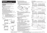
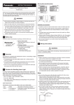
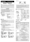
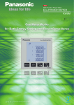
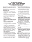
2. Parts Name
Installation instructions
KW2M-A Eco-POWER METER
4. Wiring
◆Front
Main Unit
Voltage input
terminals
Power supply
terminals
Read these instructions carefully for proper installation.
After installation, keep it in a safe place for reference when required.
Operation keys
You can download the user's manual from our website.
For User's manual
Display
http://panasonic.net/id/pidsx/global
Indicators
1. Before use
●Eco-POWER METER is designed chiefly to manage saving energy.
It is neither intended nor can it be legally used for billing.
●Eco-POWER METER is designed to be used installing in a control panel.
●Please use Eco-POWER METER according to the specification described.
Otherwise, it may malfunction or cause fire and an electric shock.
・Connect Eco-POWER METER to the power supply in compliance with
the rating.
・Refer to the wiring diagram to ensure proper wiring for the power
supply, input and output.
・Use an electric wire applicable to the rated current.
・Do not perform wiring or installation with a live line. It may also lead
to circuit burnout or fire by way of the secondary CT side opening.
●Do not connect voltage input, current input, pulse input wires parallel
to high-voltage or power cables and avoid using the same conduit.
Use shielded wires as short as possible.
●Do not turn on the power supply or input until all wiring is completed.
●Do not use at secondary side circuit of inverter. It might cause exothermic
heat or damage.
●If additional noise effects power supply line, voltage input line, current
input line, incorrect measurements may result.
●Installation and wiring must be performed by expert personnel for
electrical work or electric piping.
●Please wipe dirt of the main unit with soft cloth etc.When thinner is used,
the unit might deform or be discolored.
●Do not add an excess power to the display. It might break the inner liquid
crystal.
・Be sure to wire correctly according to the wiring diagrams.
・For supply voltage fuse protection, always protect the device with an IEC
approved or UL listed CLASS CC 2A fuse. For the protecting the voltage
measuring inputs, always protect the device with an IEC approved or UL
listed 10A fuse, circuit breaker or aupplementary protector.
This product has no built-in power switch, circuit breaker or fuse.
Therefore it is necessary to install them in the circuit near this unit.
・Do not turn on the power supply or input until all wiring is completed.
・Never open the secondary circuit of CT under applying current to load,
never remove the terminal block under applying current to load, it will
cause electric shock or breakdown CT.
◆Terminal arrangement
Power supply terminals
Terminal number
1
L+
Functions
◆Bottom view
RS485
communication
terminals
Ethernet Port
(Left:Port1
Right:Port2)
Pulse I/O
terminals
Current input
terminals
Terminal number
Functions
1
V1
2
NC
3
V2
4
NC
5
V3
6
NC
7
Vn
Measured
Voltage
NC
Measured
Voltage
NC
Measured
Voltage
NC
Measured
Voltage
The input voltage to each terminal is as follows.
Current input terminals
1
2
3
4
5
6
k
k
k
Functions CH1(CT1) CH1(CT2) CH1(CT3)
Measured current(CH1)
(unit: mm)
(tolerance:±1.0)
◆Dimensions
140
Power supply
Voltage input terminals
Terminal number
3. How to Mount
2
N−
7
8
9
10 11 12
k
k
k
CH2(CT1) CH2(CT2) CH2(CT3)
Measured current(CH2)
RS485 communication terminals
20
Terminal number
Functions
45
Terminal number
1
+
2
+
3
−
4
−
5
END
6
END
Pulse I/O terminals
85
1
2
+
−
Pulse input
Functions
■For your safety, make sure to satisfy the following conditions.
・ Overvoltage category:Ⅲ, Pollution degree 2
・ Indoor use
・ An ambient temperature of -10 to 50℃
・ An ambient non-condensing humidity of 30 to 85%RH (at 20℃)
・ Altitude of 2000m or less
48.8
65
◆How to connect the expansion unit
· Turn off the power when connecting the expansion units.
· Peel off connector label on the side before connecting.
· (Do not peel off connector labels when not connecting.)
· It expands by connecting each male connector to female connector on the
each side.
· After connecting, push the hooks into the unit to fix the expansion units.
· Up to 3 expansion units can be connected per one main unit.
Caution) Communication will be stopped or the measurement data will be lost
when the units are removed or connected with the power on.
■Do not use in the following environments.
・ Where it will be exposed to direct sunlight
・ Where inflammable or corrosive gas might be produced
・ Where it will be exposed to excessive airborne dust or metal particles
・ Where it will be exposed to water, oil or chemicals
・ Where direct vibration or shock might be transmitted
・ Where the place near high-voltage cable, power line or machineries which
occurs the big switching serge.
Hook
■Pursuant to the directive 768/2008/EC
Manufacturer : Panasonic Industrial Devices SUNX Co.,Ltd.
2431-1 Ushiyama-cho, Kasugai-shi, Aichi, 486-0901, Japan
Importer
: Panasonic Electric Works Europe AG
Rudolf-Diesel-Ring 2, 83607 Holzkirchen, Germany
Contact for CE: Panasonic Marketing Europe GmbH Panasonic Testing Center
Winsbergring 15, 22525 Hamburg, Germany
Expansion
connector
(male)
Hook
Expansion
connector
(male)
Hook
■This product has been developed / produced for industrial use only.
Hook
3
4
+
−
Pulse output(CH1)
5
6
+
−
Pulse output(CH2)
The input voltage to each terminal is as follows.
Input voltage
Terminal Phase and wire system Terminal No.
Single-phase
1- 2
100∼240VAC
[100∼240V ]
Power supply
two-wire
1-7
Single-phase two-wire
Measured Single-phase three-wire 1 - 5 - 7
0∼690VAC [0∼690V ]
voltage input Three-phase three-wire 1 - 5 - 7
Three-phase four-wire 1 - 3 - 5 - 7
◆Applicable wire (Crimp-type terminal is recommended.)
・Stripping length: 7 to 8mm
・Power supply/Measured voltage
Screw type: M3
Tightening torque: 0.5 to 0.6N・m
Sectional area: single /stranded wire 0.13 to 6mm2(AWG26 to 12)
・for 2pcs.
single/stranded wire 2pcs.×0.5 to 2.5mm2 (AWG20 to 12)
・Measured current (CT input)
Push IN type
Sectional area: single /stranded wire 0.13 to 1.5mm2(AWG24 to 16)
*Use applicable wire according to the measured current.
・RS485 communication
Push IN type
Sectional area: single /stranded wire 0.13 to 1.5mm2(AWG24 to 16)
*Use shielded wire for RS485 communication.
・Output/Input
Push IN type
Sectional area: single /stranded wire 0.13 to 1.5mm2(AWG24 to 16)
◆Applicable ferrules (by Weidmuller)
5. Wiring Diagram
H0.75/14D GR
H1.5/14D SW
1 2 3 4 5 6 7
Name
Part number
2mm2 ※
H2.5/15D BL
9019040000
9019120000
9019160000
V1 NC V2 NC V3 NC Vn
Name
H0.75/14D ZH GR
H1.5/16D ZH SW
Part number
9037410000
9037470000
Wire size
◆When using VT(voltage transformer)
・ Recommended breaker: 3 -15A (IEC approved or UL listed)
Voltage input terminals
・ Recommended fuse: Time-lag fuse Rated current 2A (IEC approved or UL listed)
1P2W
Power supply
terminals
Voltage input terminals
For 1pc.
For 2pcs.
※
Current input terminals
0.75mm2
1.25mm2
VT
2 3
4
5
6 7
NC V2
NC
V3
NC
3
4
5
6
7
8
9 10 11 12
7. For RS485 Connection
CT1
CT2
CT3
L1(R)
N
K
CT1
L
CT2
CT3
1P3W/3P3W
Power supply
Voltage input terminals
terminals
1
2
1
2 3
4
5
6 7
L+
N-
V1
NC V2
NC
V3
NC
XX
X
X
Current input terminals
1
2
3
4
5
6
7
8
9 10 11 12
CH1 CH1 CH1 CH1 CH1 CH1 CH2 CH2 CH2 CH2 CH2 CH2
CT1 CT1 CT2 CT2 CT3 CT3 CT1 CT1 CT2 CT2 CT3 CT3
k
k
k
k
k
k
Vn
(To measure
each-circuit)
X
Breaker
CT1
Load side Load side
Power
supply side
AUX
(Power supply)
L1(R)
L2(N/S)
L3(T)
K
CT3
L
CT1
3P4W
CT3
Power supply
Voltage input terminals
terminals
1
2
1
2 3
4
5
6 7
L+
N-
V1
NC V2
NC
V3
NC
XX
X
X
X
Current input terminals
1
2
3
4
5
6
7
8
◆How to connect CT
(1) Power off the measured devices.
(2) Install applicable CT.
(3) Connect CT to the terminal block.
(4) After confirm all wiring correct, turn on the power of the load
and KW2M-A.
9 10 11 12
* Connect CT wiring and terminal block surely.
It will cause CT breakdown.
* Never remove the terminal block under applying current to
load. It will cause electric shock or breakdown CT.
(To measure
each-circuit)
X
Power Supply
AUX
(Power supply)
L1(R)
L2(S)
Load side
CT1
CT2
L3(T)
CT3
N
L
CT1
CT2
CT3
Ammeter etc.
Vn terminal should be connected to N-phase which is grounded.
Primary side current
K
http://panasonic.net/id/pidsx/global
without
Ammeter
Secondary side current
L
Load
Terminal
device
Not correct
Connect terminating resistors to
the both end of the communication line
including a upper device.
Short terminal between [-] and [END] of
Eco-POWER METER connected the end
of RS485 line.
◆Connection of KW2M-A(2-wire)and KW9M(3-wire)
Terminal
Except terminals
KW9M
KW2M-A
+ − END
KW2M-A
+ −
SG A+ B−
Shielded cable
KW2M-A
Short-circuit [-] to [END].
*Do not connect
END shielded cable to [E]. +
− END
Shielded cable
Shielded cable
*Connect
Class D
8. For Input Connection
◆Pulse input
・ Contact input
R
Use highly reliable metal plated
contacts. Since the contact’ s bounce
R
time leads directly to error in the count
IN+
value, use contacts with as short
Photo
-coupler
a bounce time as possible. In general,
C
select 30Hz for max. counting speed.
IN-
・ Non-contact input (Transistor input)
Connect with an open collector.
Use the transistor with the following specifications.
VCEO=20V min. IC=20mA min. ICBO=6µA max.
Use transistors with a residual voltage of less than 2V when the transistor
is ON.
*Short-circuit impedance should be less than 1kΩ.
Open-circuit impedance should be more than 100kΩ.
Leak current in shorted is about 10mA.
・ Input wiring
Please wire up as short as possible by using a shielded wire or a metallic
electric wire tube individually.
9. For Output Connection
Breaker
Load side
Power
supply side
・ Use CT that the secondary side current is 5A or 1A.
・ One CT is needed when measuring 1-circuit of 1P2W.
Two CTs are needed when measuring 1P3W/3P3W (4 CTs for 2-circuit).
Three CTs are needed when measuring 3P4W (6 CTs for 2-circuit).
Using all CTs for one unit should be the same.
・ Use the applicable wire, or it might cause a breakdown, burnout or
electric shock.
・ When connecting CT, connect the secondary side to the terminal of the
main unit first, and after that wire the primary side to a load electric wire.
Incorrect order might cause an electric shock or break CT.
・ The CT has polarity. Wire correctly according to the K and L marks.
Wrong direction can’ t measure correctly.
・ If there is some distortion by harmonic or waveform, it may not measure
correctly. Please check with the actual system before adopts it.
・ Separate the wiring (strong electric part) of the measured voltage input
terminal (operating power supply terminal) from the CT cable.
It may not satisfy the accuracy due to noise.
CH1 CH1 CH1 CH1 CH1 CH1 CH2 CH2 CH2 CH2 CH2 CH2
CT1 CT1 CT2 CT2 CT3 CT3 CT1 CT1 CT2 CT2 CT3 CT3
k
k
k
k
k
k
Vn
Breaker
K
Correct
6. How to attach Current Transformer
X
X
AUX
(Power supply)
◆RS485 communication wiring
L1(R)
L2
(S)
L3(T)
N
(To measure
each-circuit)
(To measure each-circuit)
Breaker
Power
supply side
2
Load side Load side
XX
1
CH1 CH1 CH1 CH1 CH1 CH1 CH2 CH2 CH2 CH2 CH2 CH2
CT1 CT1 CT2 CT2 CT3 CT3 CT1 CT1 CT2 CT2 CT3 CT3
k
k
k
k
k
k
Vn
Internal circuit
1
V1
k
CT(secondary current 1A or 5A)
◆PhotoMOS relay output
・ PhotoMOS relay is mounted in this product, therefore it has no polarity.
・ Wire up to 100m for output connection.
Output (rated capacity 30V AC/DC, 0.1A)
Internal circuit
2
N-
To RS485 device
1
L+
OUT
COM
8A3 M55 7000 1
Overseas Sales Division (Head Office)
2431-1 Ushiyama-cho, Kasugai-shi, Aichi, 486-0901, Japan Phone: +81-568-33-7861 FAX: +81-568-33-8591
© Panasonic Industrial Devices SUNX Co., Ltd. 2015 PRINTED IN JAPAN
About our sale network, please visit our website.