1
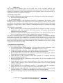
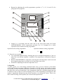
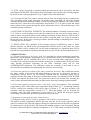
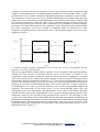
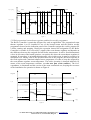
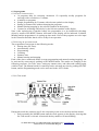
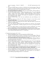
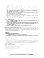
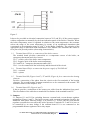
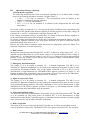
INTIEL
THE ELECTRONICS ON YOUR SIDE
Electrical Boiler Controller
INT0001C
INT0004D
INT0004F
User’s Manual
tel.: 00359 596.333.66 ||| fax: 00359 596.325.80 ||| [email protected] ||| www.intiel.com
9 Peter Beron Str., Pomorie 8200, Bulgaria
1
I.
Application
The present User’s Manual takes an all round view of the operation principle and
characteristics of the Electrical Boiler Controller with capacity up to 60 kW. The Controller
regulates all parameters of the central heating system (equipped with an electrical boiler) in
compliance with the environment conditions.
1. Principle of operation
The Controller regulates the water heating system by affecting to the following components:
• Electrical heating elements and
• Circulation pump
In fact the main principle of the operation is based on a regulation of the capacity of the
heating elements in relation to the temperature in the heated premises (rooms). The control is
provided by step regulation of the heating element capacity of 2 kW (respectively 4 kW when
the capacity is bigger than 30 kW) by means of changing the number of switched on heating
sections.
The controller is consisted of:
• Basic control module (electrical boiler module) that is equipped with built-in weekly
programmer and boiler regulator. The boiler module can operate independently
without room thermo regulator.
• Module for temperature measurement and assignation in the heated premises that in
fact is a room thermo regulator with or without outer weekly programmer.
The Boiler Controller operates as a proportional capacity regulator in compliance with the
temperature. In fact that allows using that part of the installed capacity, necessary for keeping
the desired temperature level without over-expenditure of the electrical energy surplus. The
previous mentioned principle avoids any water temperature fluctuations in the electrical boiler
during the fixed operation regime that extends the life expectancy of the water heating
components and increases its safety.
2. Regulation and signalization
2.1. Front indication panel – Figure 1.
• Two positional digital display (position 2). It shows the real water temperature or the
assigned temperature level of the Boiler Controller in Degrees Celsius.
• Digital LED display (position 1). It relates only to electrical boilers with built-in
weekly programmer, showing the day, the time and the selected program.
• Button AUTO/OFF (position 8). It switches the system into heating regime, defined
by preliminary set program or a continual stop.
• Light indication of the circulation pump state (position 3). It appears when the
circulation pump is switched on.
• Button ASSIGNED/REAL temperature (W/X) (position 10). It shows assigned or real
water temperature level.
• Light indication for low water volume (position 4). It is active when the water level
volume in the system is lower than the lowest possible level for safety heating
elements operation.
• Light indication for an overheating (position 5). It appears when the emergency
thermostat is active as a result of high water temperature in the boiler.
• Eight positional light indication, concerning the number of the working heating
elements (position 13). It shows the percentage of the used boiler capacity.
• Element for adjusting the desired water temperature level of the boiler water (position
11).
tel.: 00359 596.333.66 ||| fax: 00359 596.325.80 ||| [email protected] ||| www.intiel.com
9 Peter Beron Str., Pomorie 8200, Bulgaria
2
•
Buttons for adjusting the weekly programmer (position 6, 7, 9, 12, 14, and 15). See
paragraph 6.Set programs.
3
2
SYS-M
1
5
C
TERMOCONTROL
100
13
75
8
15
50
OFF AUTO
25
.
10
PROG.
.
SET
MODE
.
X
W
6
RESET
.
.
ON/OFF
POWER %
.
11
W
.
.
ENTER
TIMECONTROL
9
•
14
12
7
Jumper J1 is accessible from the back side of the front panel under the button
ASSIGNED/REAL (W/X) temperature (position 10). It is designed for a boiler
operation with or without weekly programmer.
Operation with weekly programmer
J1
Operation without weekly programmer
J1
2.2. Room thermo regulator.
• Two positional digital display, showing the real or assigned temperature of the air,
where the room thermo regulator is installed. The temperature is indicated in Degrees
Celsius.
• Button ASSIGNED/REAL temperature, showing the real temperature in the room and
the assigned temperature level that is to be kept in the same room.
• Element for adjusting the desired temperature level.
3. Operation
3.1 OFF regime. It is used during continual boiler stop. It can be chosen by the button
AUTO/OFF on the front panel. When the Controller is in OFF regime, the heating elements
are switched off. The room thermostat does not affect to the general operation, but it measures
and shows the real room temperature. Also, during that regime the circulation pump starts for
10 minutes a day in order to avoid its blocking, due to a fur accumulating. Generally the OFF
regime is appropriate during long stop boiler operation, even during the winter. There is no
risk of water freezing in the systems, due to all activated protections.
tel.: 00359 596.333.66 ||| fax: 00359 596.325.80 ||| [email protected] ||| www.intiel.com
9 Peter Beron Str., Pomorie 8200, Bulgaria
3
3.2 AUTO regime. It provides a regular heating operation and it can be selected by the front
panel button AUTO/OFF. The heating element operation is provided by the selected program,
by means of the weekly programmer or by a signal of the room thermostat.
3.3 Circulation PUMP. The pump is started when at least one heating section is switched on.
The circulation pump keeps operation 10 minutes after switching off all boiler heating
elements spreading accumulated heating of the boiler through the radiators. The pump will be
started by force, when the boiler temperature drops bellow 15 0C in order to pass the whole
water volume in the system through the boiler temperature sensor. The maximal stop of the
circulation pump is 42 hours.
3.4 ELECTRICAL HEATING ELEMENTS. The maximal number of heating element sections
is 15. Their in serial switching is provided by connection to the next power supply phase in
order to ensure an equal electrical circuit loading. Switching of more than one section will be
performed consecutively and each next one will be connected with 2 sec. delay in relation to
the previous one. In this way it can be provided a smooth loading or unloading of the circuit,
avoiding any current rushes.
3.5 REGULATION. The regulation of the heating capacity is fulfilled by room or boiler
thermo regulator. As much as the real temperature becomes closer to the boiler one, more
heating sections will be switched off. In case both temperatures are equalized there will be
kept the necessary number of heating elements that is to provide the desired temperature level.
4. PROTECTIONS
4.1 Thermal protection of the boiler body. It is provided by electro-mechanical emergency
thermostat, which boundary temperature level is preliminary fixed by the manufacturer. All
heating elements will be switched off by force, in case its fixed boiler temperature will be
exceeded. The circulation pump will continue working for 10 minutes and will stop after that.
After thermal protection activating on the front Controller panel can be seen
OVERHEATING indication. The indication cannot be restored by itself and it can be
deactivated only manually after eliminating the reason for its activating.
4.2 Protection against low volume of the water contents in the boiler. Due to different reasons
the water volume in the boiler and whole heating system can be decreased, because of
evaporation, leakage and so on. All heating elements and the circulation pump will be
switched off after activating of the above mentioned protection. An indication LOW WATER
LEVEL will light on the front panel. The protection waits for 40 seconds after restoring the
water volume and afterwards smoothly switches on the necessary heating elements number.
4.3 Protection against freezing the water in the boiler, pipes and radiators. The circulation
pump starts by force if the boiler water temperature drops bellow 15 0C. All heating elements
will be switched on smoothly if the boiler water is bellow 6 0C and that operation will
continues until the temperature exceeds 8.5 0C. Then the heating will be switched off
smoothly, while the water temperature is kept bellow 15 0C. When the protection against
overheating is activated the protection against freezing is blocked.
5. Equipment versions and operation characteristics
5.1 Equipped with a built-in weekly programmer and without a room thermostat.
The built-in weekly programmer defines the time intervals for the boiler operation and its
pause in relation to the selected program. During the operation interval the boiler assignation
is constant and it can be fixed by the element for manual settings on the front panel. During
the pause interval the Boiler Controller assignation is 10 0C that means switched off heating
tel.: 00359 596.333.66 ||| fax: 00359 596.325.80 ||| [email protected] ||| www.intiel.com
9 Peter Beron Str., Pomorie 8200, Bulgaria
4
elements. Concerning the present equipment version (with a built-in weekly programmer and
without a room thermostat) it is recommended the installation of thermostatic valves in each
of the heated rooms, in order to obtain an individual temperature regulation for each of them.
The temperature of the boiler water is to be defined manually by the costumer and it does not
relate to the room temperature, but the thermostatic valves affect to the Boiler Controller and
the electrical capacity by fixing the dose of the consumed heating capacity. During an
operation interval the boiler keeps the water temperature level permanent by variable capacity
percentage. The main disadvantage of this equipment version is that due to the manual setting,
the water temperature can be not enough or redundant high for following the room
temperature assignation fixed by thermostatic valves. The operation regime can be seen on the
diagram on Figure 2.
Program
ON
OFF
t [s]
tк ,tкз
Manual
10°С
t [s]
Figure 2
5.2 Without a built-in weekly programmer, but with an outer weekly programmable thermo
regulator, like CM 51 (Honeywell).
The outer programmable weekly thermo regulator is to be installed in the heated premises,
defining the time periods of operation and the pause of the boiler in relation to the
temperature in the premises. During the operation interval the boiler assignation is constant
and it can be fixed by the element for manual settings on the front panel. During the pause
interval the Controller assignation is fixed at 10 0C. It can be fixed thermostatic valves in all
rooms of the heated premises, except this one where the weekly programmable thermostat is
mounted. In case there is installed thermostatic valve in this room also, it must be opened to
its maximum level in order to avoid the influence to the weekly programmable thermostat
operation. The temperature of the boiler water is to be fixed manually and it does not
correspond to the room temperature. The thermostatic valves affect to the Boiler Controller
and the electrical capacity by fixing the dose of the consumed heating capacity and the room
temperature affects to the duration of the operation boiler intervals. The advantage of this
version is the convenient control of the boiler directly from the room and the disadvantage is
the frequent switching of the boiler, in order to keep the boiler temperature in accordance with
its assigned level. The boiler operates in a regime that is far away of the fixed one, with
significant temperature fluctuations. The operation of the heating installation can be seen on
the diagram bellow (Figure 3).
tel.: 00359 596.333.66 ||| fax: 00359 596.325.80 ||| [email protected] ||| www.intiel.com
9 Peter Beron Str., Pomorie 8200, Bulgaria
5
250°С
180°С
tс ,tсз [°С]
150°С
150°С
t [s]
Manual
tк ,tкз [°С]
10°С
t [s]
Figure 3
5.3 With proportional room thermo regulator and built-in weekly programmer.
The Boiler Controller is particular designed for such an application. The proportional room
thermo regulator is to be installed in one of the heated rooms and the built-in weekly
programmer located on the indication panel of the Controller assigns the weekly program for
a boiler starting and stopping. During the operation interval the assignation of the Boiler
Controller is variable. It is received by a signal of the room thermo regulator and depends on
the difference between the assigned and real boiler temperature. It can be fixed thermostatic
valves in all rooms of the heated premises, except this one where the room thermo regulator is
mounted. In case there is an installed thermostatic valve in this room, it must be opened to its
maximum level. During each of the operation intervals of the program, the boiler operates in
the fixed regime and a maximal adapted water temperature, in order to keep the assigned by
the room thermo regulator room temperature. The boiler operation is changed indirectly by
means of the room temperature variation. (see the next part of the sentence). The overexpenditure is eliminated and this version is the most economical one, keeping the recourses
of the installation. Its operation is shown on Figure 4.
Program
ON
OFF
t [s]
tс ,tсз
t [s]
250°С
Automatic
10°С
t [s]
Figure .4
tel.: 00359 596.333.66 ||| fax: 00359 596.325.80 ||| [email protected] ||| www.intiel.com
9 Peter Beron Str., Pomorie 8200, Bulgaria
6
6. Set programs.
6.1 General characteristics.
• 16 programs daily for start/stop, maximum 112 repeatedly weekly programs for
start/stop with a resolution of 1 minute.
• 6 initially set programs.
• Simple programming by 5 buttons with relevant symbols on the display.
• Setting-up summer time without changing the programs.
• Manual starting/stopping by the relevant symbols on the display.
• Counter for switching with a delay by the relevant symbols on the display.
Note: After replacing the Controller battery the programmer is to be initialized with sharp
object by means of the RESET button. Afterward on the display will be indicated 12:00AM,
Monday and the programmer is in setting-up time mode. Now all the programs are to be input
in the Controller and after that it will be ready for an operation.
6.2 Selecting an operation mode.
The programmer can operate in the following modes:
• Setting time (Set Time).
• Automatically (Auto).
• Programming.
• Counting.
• Summer time
• Manual starting and stopping.
Each of the above mentioned modes (except programming and manual starting/stopping) can
be activated by consecutively pushing of the MODE button. The modes are changing in the
following sequence: Set Time, Auto, setting-up summer time, and afterwards starting again
with Set Time. The Manual mode for start/stop can be activated any time by pushing ON/OFF
button, and the Programming mode can be activated in the AUTO mode.
6.3 Set Time mode
During this mode the costumer can fix the current day in the week, the hour and the minute.
1. Push repeatedly the MODE button until the clock appears on the display, showing that
Set Time mode is selected. Afterwards the day number will start blinking.
tel.: 00359 596.333.66 ||| fax: 00359 596.325.80 ||| [email protected] ||| www.intiel.com
9 Peter Beron Str., Pomorie 8200, Bulgaria
7
2. Push the SET button to select the correct day in the week. Each pushing increases the
number of activated day in the range of 1 to 7, repeating that range after keeping the
SET button pushed.
3. Press the ENTER button in order to confirm the select day in the week. The time
indication starts blinking.
4. Fix the correct hour by means of SET button. Keep the button pressed in order to
select the hour faster.
5. Push the ENTER button to confirm the selected hour. The minutes indication starts
blinking.
6. Select the minutes by means of SET button.
7. Press the ENTER button for a confirmation.
8. Press the MODE button to leave the Set Time mode and go to another operation mode.
6.4 Automatically mode (AUTO).
During this mode the weekly programmer automatically starts/stops the boiler in compliance
with the selected program regime.
Press the MODE button repeatedly until the indication AUTO appears on the digital display.
Generally there are 16 individual programs for daily start/stop that can be selected by the
costumer. Also there are 6 additional initially assigned programs that are indicated on the
display in the range of P17 up to P22. The costumer cannot change the assigned time for
start/stop of the previous mentioned 6 programs, but can select the day of operation for each
of them. Find out bellow the programs assigned time for a starting/stopping.
PROGRAM
Р17
Р18
Р19
Р20
Р21
Р22
STARTING
6 : 30
7 : 00
7 : 30
18 : 00
19 : 00
20 : 00
STOPPING
7 : 00
7 : 30
8 : 00
19 : 00
20 : 00
21 : 00
The program assignation with the grater number remains valid, in case, the time of
starting/stopping for some programs coincided. On the other hand, the stopping is with higher
priority if the starting time coincides with the stopping one.
For example:
P1 time ON = P1 time OFF – It will be valid P1 OFF
P1 time ON = P2 time OFF – It will be valid P2 OFF
P2 time ON = P1 time OFF – It will be valid P2 ON
P1 time ON = P1 time OFF = P2 time OFF – It will be valid P2 OFF
6.5 Programming mode
During this mode the costumer is able to activate or deactivate the starting/stopping of each
program in AUTO mode or to change the each program duration. The AUTO mode is to be
selected before going into PROGRAMMING mode. Press the PROG button afterwards and
on the display will appear the symbol P and the number of the program. The lamp indication
shows the state of the boiler – for starting or stopping.
6.6 Programs fixed by the costumer.
1. Press repeatedly the PROG button in order to select the program and the assignation
that you want to modify. With each pressing the programs are changed in the
following sequence: P01 ON (starting time concerning a first program) – P01 OFF
tel.: 00359 596.333.66 ||| fax: 00359 596.325.80 ||| [email protected] ||| www.intiel.com
9 Peter Beron Str., Pomorie 8200, Bulgaria
8
(time for stopping) – P02 ON – P02OFF …………..P22 OFF and then back to P01
ON.
2. Press the ON/OFF button to activate or deactivate the selected program. When the
program is selected the display shows the day number in the week and the time. When
the program is deactivated on the display can be seen only --:-3. Press the ENTER button in order to modify the current program. The day number of
the program activating starts blinking.
4. Press the SET button in order to change the day/days in the week in the following
sequence: MON-SUN (Monday – Sunday), MON-FRI (Monday – Friday), FRI-SUN
(Friday – Sunday), SAT – SUN (Saturday – Sunday), MO (Monday), TU (Tuesday),
WE (Wednesday), TH (Thursday), FR (Friday), SA (Saturday), SU (Sunday) and
afterwards back to MON – SUN.
5. Press the ENTER button to go into time modification, that starts blinking on the
display.
6. Modify the time by pressing the SET button. Keeping the same button pressed
changes the time faster.
7. Press the ENTER button to go into minutes modification that starts blinking.
8. Modify the minutes by pressing the SET button. When that button is pressed the
minutes are changed faster.
9. Press once again the ENTER button that terminate the correction of the selected
program. The modification of another program can be done by pressing the PROG
button.
10. In case the PROG button is pressed during the program modification, the current
process of modification will be terminated and the next program will be chosen.
11. Press the MODE button to end the programming and to go at first into AUTO mode.
The weekly programmer will go automatically into AUTO mode if no one button is
pressed during Programming mode for 15 seconds time.
6.7 Initially fixed programs (P17 – P22).
1. During programming mode select the program by the PROG button.
2. Press the ON/OFF button to activate or deactivate the selected program. When the
program is selected the display shows the day number in the week and the time. When
the program is deactivated on the display can be seen only --:-3. Press the ENTER button in order to modify the current program. The day number of
the activated program starts blinking. Concerning initially fixed programs it can be
modified only the day of activation.
4. Press the SET button in order to change the day/days in the week in the following
sequence: MON-SUN (Monday – Sunday), MON-FRI (Monday – Friday), FRI-SUN
(Friday – Sunday), SAT – SUN (Saturday – Sunday), MO (Monday), TU (Tuesday),
WE (Wednesday), TH (Thursday), FR (Friday), SA (Saturday), SU (Sunday) and
afterwards back to MON – SUN.
5. Press the ENTER button to terminate the modification of the selected program. It can
be selected another program for modification by pressing the PROG button.
6. In case the PROG button is pressed during the program modification, the current
process of modification will be terminated and the next program will be chosen.
7. Press the MODE button to end the programming and to go first into AUTO mode. The
weekly programmer will go automatically into AUTO mode if no one button is
pressed during Programming mode for 15 seconds time.
tel.: 00359 596.333.66 ||| fax: 00359 596.325.80 ||| [email protected] ||| www.intiel.com
9 Peter Beron Str., Pomorie 8200, Bulgaria
9
6.8 Counting mode
During this mode the boiler state changes after passing a preliminary set certain period of
time. It means that the weekly programmer will act with a preliminary fixed delay.
1. Press repeatedly the MODE button until the sandglass indication appears on the display.
The factory setting counting time is 10 minutes.
2. Set the counting time by pressing the SET button (each pressing of that button extend
the counting time with 10 minutes). The maximal counting time is 90 minutes that in
the end returns to the beginning of 10 minutes.
3. Press ENTER button to start the counting. If any button is not pressed in 15 seconds
time the counting will start automatically.
4. During the counting the sandglass indication blinks.
5. Pressing ENTER button during the counting mode switches the display indication
between the remaining and the real time.
6. The boiler will be switched in another operation state, after passing the fixed counting
time.
6.9 Summer time mode.
1. Press repeatedly the MODE button, until the symbol of the summer time appears (a
letter “S” on the top left side).
2. Press the ENTER button to switch between summer and winter time. In summer time
mode the clock shows one hour more than in the winter time and on the display is
indicated the symbol “S”.
3. Press the MODE or ON/OFF button to leave the summer time mode.
6.10 Manual starting/stopping mode.
During this regime is to be used the ON/OFF button. During this regime the boiler will stop
operation, in case it was switched on or conversely. A hand symbol shows on the display to
mark the Manual starting/stopping mode is selected. The manual mode can be activated from
any other mode, except Programming one.
II. Wiring
1. Terminal boards and connections.
1.1 Terminal board X3 for a circulation pump connection.
It is used for a connection of a circulation pump with a power supply of 220V/50Hz/AC
and a nominal current of 8A.
X3.1 – a neutral
X3.2 – a phase
1.2 Terminal board X1 for a connection of a room thermo regulator or an equithermal
transmitter – model INT0066A.
It is used for a connection of the proportional room thermo regulator, the equithermal
transmitter with a four-core cable 4x0.75mm2 (Figure 6 and 7) or a programmable thermo
regulator with relay output by means of three-core cable 3 x 0.75 mm2 (Figure 5).
X1.1 - (+16V/DC)
X1.2 – common connection.
X1.3 - (-16V/DC).
X1.4 – current signal in the range 0-20mA.
X1.5 – internal assignation input 0-3V.
X1.6 - internal assignation output 0-3V.
tel.: 00359 596.333.66 ||| fax: 00359 596.325.80 ||| [email protected] ||| www.intiel.com
9 Peter Beron Str., Pomorie 8200, Bulgaria
10
Figure 5.
It has to be provided an electrical connection between X1.5 and X1.6 if the system operates
with an assignation set manually by the front indication panel of the Boiler Controller. When
the boiler temperature water is regulated in relation to the room temperature, the costumer
selects the range of the room temperature by means of an equithermal transmitter that
corresponds to an assignation range of 6-90 0C to the Boiler Controller. The selection of the
appropriate range is described in the transmitter User's Manual. The transmitter B1 button is
to be placed in pressed position (decreasing characteristics).
1.3 Terminal board X2 for a connection of the boiler sensors.
The terminal board provides connections to a temperature sensor of the boiler, an
emergency thermostat and a level sensor.
X2.1 – positive pole of the boiler water temperature.
X2.2 - negative pole of the boiler water temperature.
X2.3 and X2.4 – emergency thermostat contact (NC)
X2.6 – is to be connected to the boiler body and the neutral of the circuit.
1.4 Terminal board X4 for a connection the power supply of 220/50Hz/AC
X4.1 – a neutral
X4.2 – a phase
1.5 Terminal bord X6 (Figure 6 and 7), X7 and X8 (Figure 6) for a connection the heating
elements.
Provide a connection of the phase from the circuit to the first terminals of the heating
elements. The second heating elements terminals are to be connected to the neutral. The
nominal current of each output is 16A.
1.6 Terminal board X5 (Figure 6 and 7)
It has to provide a connection of the twenty-core cable from the indication front panel.
The first feather of the cable has to match the first feather of the terminal board X5.
2. Jumpers.
2.1 Jumpers J11 and J12 for switching between a manual and a room thermo regulator
assignation (Figure 6 and 7). The boiler operates with a manual assignation fixed by the
indication front panel when the bridge is in position J11. In this case the room thermo
regulator operation does not affect the boiler operation. Terminals X1.5 and X1.6 have to
be connected by an outer bridge if the terminal board X1 is not connected to the
programmable thermo regulator with a relay output.
tel.: 00359 596.333.66 ||| fax: 00359 596.325.80 ||| [email protected] ||| www.intiel.com
9 Peter Beron Str., Pomorie 8200, Bulgaria
11
When the bridge is placed in position J12, the boiler operates in compliance with the
assignation defined by the proportional room thermo regulator or the equitermal
transmitter.
2.2 Jumper J2 (Figure 6) and J1 (Figure 7). They are always placed sending a time
frequency for the circulation pump cycle.
2.3 Jumper J3
• The protection against low level of the water volume is deactivated, when it is placed
in position J31 (Figure 6).
• The protection against low level of the water volume is activated, when it is placed in
position J32 (Figure 6).
• The protection against low level of the water volume is activated when J3 is not
placed (Figure 7)
• The protection against low level of the water contents is activated when J3 is placed
(Figure 7)
2.4 Jumper J4. Fix the boiler operation to a floor-heating or radiators installation.
0
• The maximum boiler outlet temperature is 50 C, when the jumper is placed in
position J41 (suitable for floor heating) and the maximum boiler outlet temperature is
90 0C, when the jumper is placed in position J42 (suitable for radiator
heating).(Figure 6).
0
0
• Position J41 – 90 C, position J42 – 50 C (Figure 7).
Note: Figure 6 – boilers with a capacity within the range of 18 - 60kW.
Figure 7 – boilers with capacity up to 12kW.
Figure 8 – boilers with a capacity within the range of 12 – 30 kW
tel.: 00359 596.333.66 ||| fax: 00359 596.325.80 ||| [email protected] ||| www.intiel.com
9 Peter Beron Str., Pomorie 8200, Bulgaria
12
1
2
3
4
N
X3
X4
1 2
T
1 2
FS2
FS1
X1
S
R
2,0A
0,5A
1
2
3
4
5
6
+
-
N
1
2
3
4
5
6
D4
X2
Да Не
J3
X5
J42
J41
J2
J12
J11
INT0004D
D31
90 oC
50 oC
X7
X8
X6
N
Figure 6
tel.: 00359 596.333.66 ||| fax: 00359 596.325.80 ||| [email protected] ||| www.intiel.com
9 Peter Beron Str., Pomorie 8200, Bulgaria
13
FS1
Figure 7
tel.: 00359 596.333.66 ||| fax: 00359 596.325.80 ||| [email protected] ||| www.intiel.com
9 Peter Beron Str., Pomorie 8200, Bulgaria
14
Стаен терморегулато р
Д
+ -
R
N
+12 V
GN D
-12 V
OUT
Еквитермен трансмитер
S
T
АП
X1 1 2 3 4 5 6
1 2
3 4
1
2
1 2
X3 Fs1
D4
+16V
GND X1
X4
N
INT0004F
1
2
3
4
5
6
Fs2
1
2
3 -16V
4
IN
5
6
X2
X5
1
J42
J41
9 0 oC
50 oC
X8
Задание
Външно
Вътрешно
J12
J11
Да Не
Ниво
J3
X7
J2
X6
ÄÍ
ÄÒ
ÁÒ
N
Фиг.8
Figure 8
tel.: 00359 596.333.66 ||| fax: 00359 596.325.80 ||| [email protected] ||| www.intiel.com
9 Peter Beron Str., Pomorie 8200, Bulgaria
15
III.
Operation efficiency check-up
1. Room thermo regulator.
The following measurements of the room thermo regulator are to be taken with a voltage
meter on its terminals towards to terminal 2 (Figure 6 and 7):
• (+14V) – (+17V) DC on terminal 1. The measurement varies in relation to the
number of switched on heating elements.
• (-14V) – (-17V) DC on terminal 3.
• (0V) – (+1.2) V DC on terminal 4, in relation to the assigned and the real room
temperature.
In case the voltage on terminals 1 or 3 are missed, check the condition of the connection cable
between the boiler and the room thermo regulator as well the presence of the same voltage on
terminals X1.1 and X1.3 of the Boiler Controller (Figure 6 and 7).
If the voltage on terminal 4 misses, it means there is a failure in the room thermo regulator or
in the connection cable between the terminal 4 and the boiler.
In case the voltage measurements are in the above mentioned measurement ranges, press the
room thermo regulator element on the front panel and turn it in order to check the correct
indication change from 0 up to 30 0C.
Release the room thermo regulator button and touch its temperature sensor by finger. The
indicated temperature is to start increasing.
2. Boiler sensor.
Measure the voltage between terminals X2.1 and X2.2. It has to be in the range of 0.5 – 0.7 V
depends on the temperature in case the boiler sensor is in a good condition. If the voltage is
grater than 1V, it means that the sensor is cut off or it is connected with wrong terminals
polarity. In case the voltage is lower that the above mentioned range, it means that the sensor
is connected in a short circuit.
3. Emergency thermostat input.
The jumper J1 is to be placed in position J11 – a manual assignation. The AP is to be
switched off. Maximal assignation is to be fixed by the indication front panel in order to start
an operation all heating elements. One of the cables connected to X2.3 or X2.4 is to be
disconnected. A light indication for OVERHEATING appears (position 5 of Figure 1). All
heating elements must immediately stop an operation (it can be observed by the indication),
and the circulation pump goes on operation for next 10 minutes.
4. Input of water level sensor
The jumper J1 is to be placed in position J11 – a manual assignation. The AP is to be
switched off. Maximal assignation is to be fixed by the indication front panel in order to start
an operation all heating elements. The cable connected to X2.5 is to be disconnected. A light
indication for LOW LEVEL appears (position 4 of Figure 1). All heating elements and the
circulation pump must immediately stop an operation.
5. Protection against freezing
The button AUTO/OFF of the indication front panel is to be placed in position OFF. The AP
is to be switched off. The boiler sensor of terminal X2.1 is to be disconnected. A light
indication D4 of the Boiler Controller appears. All heating elements and the circulation pump
starts consecutively (can be observed by the indication).
6. Boiler Controller
The button X/W is to be released in position X. In this way it will be measured the current
water temperature of the boiler. The button X/W is to be pressed in position W. The assigned
tel.: 00359 596.333.66 ||| fax: 00359 596.325.80 ||| [email protected] ||| www.intiel.com
9 Peter Beron Str., Pomorie 8200, Bulgaria
16
water temperature level is to be increased above its current level by the indication front panel,
observing in the same time the number of the switched on heating elements. All heating
elements are to be switched on, in case the difference between those two temperatures reaches
8 0C.
VI.
Warranty
The warranty period is 24 months following the purchase date of the unit or its
installation by an authorized Engineering Company, but not exceeding 28 months after the
production date. The warranty is extended to the malfunctions that occur during the warranty
period and are result of the production reasons or defective used parts.
The warranty does not relate to malfunctions corresponding to not-qualified
installation, activities directed to the product body interference, not regular storage or
transport.
The repairs during the warranty period can be done after correct filling of the
manufacturer warranty card
Warranty Card
Manufacturer: INTIEL
Product type
Production number
Production date
Dealer confirmation
Purchase date
Invoice number
Dealer’s name, address and stamp
Seller’s name and signature
Installation Date
Date
Company (address, stamp)
Installer’s name and signature
tel.: 00359 596.333.66 ||| fax: 00359 596.325.80 ||| [email protected] ||| www.intiel.com
9 Peter Beron Str., Pomorie 8200, Bulgaria
17