1
© 2013 GEOVAP, spol. s r.o. All rights reserved.
GEOVAP, spol. s r.o.
Cechovo nabrezi 1790
530 03 Pardubice
Czech Republic
+420 466 024 618
http://www.geovap.cz
Products that are referred to in this document may be trademarks and/or registered trademarks of the
respective owners.
While every precaution has been taken in the preparation of this document, GEOVAP, spol. s r.o. assumes no
responsibility for errors or omissions, or for damages resulting from the use of information contained in this
document or from the use of programs and source code that may accompany it. In no event shall GEOVAP, spol.
s r.o. be liable for any loss of profit or any other commercial damage caused or alleged to have been caused
directly or indirectly by this document.
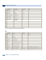
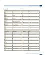
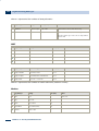
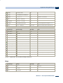
Table of Contents
Table of Contents
1
1.1
Reliance ..................................................................................................................................... 1
About......................................................................................................................................
Reliance 1
1.2
Reliance
......................................................................................................................................
SW Modules 2
2
2.1
Reliance
.....................................................................................................................................
Design Development Environment 7
Introduction ...................................................................................................................................... 9
2.2
Reliance
......................................................................................................................................
Main Features 11
2.2.1
2.2.2
End User-Intended
....................................................................................................................
Features 11
Systems
....................................................................................................................
Integrator-Intended Features 20
3
3.1
Main.....................................................................................................................................
Menu 31
File Menu ...................................................................................................................................... 32
3.2
Edit Menu ...................................................................................................................................... 34
3.3
3.2.1
Transform .................................................................................................................... 39
View......................................................................................................................................
Menu 40
3.4
Managers
......................................................................................................................................
Menu 41
3.5
Project
......................................................................................................................................
Menu 43
3.6
Tools......................................................................................................................................
Menu 45
3.7
Window
......................................................................................................................................
Menu 46
3.8
Help......................................................................................................................................
Menu 47
4
4.1
Tool Windows ..................................................................................................................................... 49
Component
......................................................................................................................................
Manager 50
4.2
Window
......................................................................................................................................
Manager 52
4.3
Layer......................................................................................................................................
Manager 55
4.4
Visual
......................................................................................................................................
Linking 56
4.5
Information
......................................................................................................................................
Window 58
5
5.1
Setting
.....................................................................................................................................
Up the Development Environment 59
Configuring
......................................................................................................................................
the Toolbars 60
5.2
Configuring
......................................................................................................................................
the Component Palette 62
Reliance 4 – Development Environment
i
ii
Table of Contents
5.3
Environment
......................................................................................................................................
Options 64
5.3.1
5.3.2
5.3.3
5.3.4
5.3.5
5.3.6
5.3.7
5.3.8
5.3.9
5.3.10
5.3.11
5.3.12
5.3.13
Paths .................................................................................................................... 64
Keyboard
....................................................................................................................
Shortcuts 65
Managers .................................................................................................................... 65
String
....................................................................................................................
Manager 66
Picture
....................................................................................................................
Manager 66
Script
....................................................................................................................
Manager 67
Script
....................................................................................................................
Debugging 71
Visualization
....................................................................................................................
Windows 71
Window
....................................................................................................................
Layout 73
File Types .................................................................................................................... 73
Connection .................................................................................................................... 75
License .................................................................................................................... 75
Update .................................................................................................................... 76
6
6.1
Visualization
.....................................................................................................................................
Project 77
Create
......................................................................................................................................
New Project Wizard 78
6.2
Project
......................................................................................................................................
Conversion Wizard 79
6.3
Creating
......................................................................................................................................
a Project Shortcut 80
6.4
Project
......................................................................................................................................
Diagnostics Wizard 81
6.5
Backup
......................................................................................................................................
Project Wizard 83
6.6
Restore
......................................................................................................................................
Project from Backup Wizard 84
6.7
Find ......................................................................................................................................
Object Usages Wizard 85
6.8
Replace
......................................................................................................................................
Object Properties Wizard 86
6.9
Export
......................................................................................................................................
Project for Remote Users Wizard 87
6.10 Project
......................................................................................................................................
Information 92
6.11 Visualization
......................................................................................................................................
Window 93
6.11.1
Creating
....................................................................................................................
a New Window 93
6.11.2
Duplicating
....................................................................................................................
a Window 94
6.11.3
Designing
....................................................................................................................
a Window 95
6.11.4
Creating
....................................................................................................................
a Window Template 96
6.11.5
Embedding
....................................................................................................................
a Window Template 97
6.11.6
Window
....................................................................................................................
Properties 98
6.12 Project
......................................................................................................................................
Options 105
6.12.1
6.12.2
6.12.3
Project .................................................................................................................... 105
SQL .................................................................................................................... 105
Alarms/Events .................................................................................................................... 106
Reliance 4 – Development Environment
Table of Contents
6.12.4
6.12.5
6.12.6
6.12.7
6.12.8
6.12.9
6.12.10
6.12.11
6.12.12
6.12.13
6.12.14
Runtime .................................................................................................................... 108
Access
....................................................................................................................
Rights 110
Windows .................................................................................................................... 111
Telephone
....................................................................................................................
Service Providers 112
DDE
....................................................................................................................
Sharing 112
Web .................................................................................................................... 113
Languages .................................................................................................................... 114
Scripts .................................................................................................................... 115
Components .................................................................................................................... 117
Objects .................................................................................................................... 118
Timers .................................................................................................................... 118
7
7.1
Components ..................................................................................................................................... 119
Common
......................................................................................................................................
Component Properties 120
7.2
7.1.1
Basic .................................................................................................................... 120
7.1.2
Alignment .................................................................................................................... 121
7.1.3
Dynamic .................................................................................................................... 122
7.1.4
Menu .................................................................................................................... 123
7.1.5
Scripts/Actions .................................................................................................................... 123
7.1.6
Security .................................................................................................................... 124
Standard ...................................................................................................................................... 125
7.2.1
7.2.2
7.2.3
7.2.4
7.2.5
7.2.6
7.2.7
7.2.8
7.2.9
7.2.10
7.2.11
7.2.12
7.2.13
7.2.14
7.2.15
7.2.16
7.2.17
7.2.18
Display .................................................................................................................... 126
Button .................................................................................................................... 129
Text .................................................................................................................... 132
Active
....................................................................................................................
Text 134
Bevel .................................................................................................................... 137
Picture .................................................................................................................... 138
Active
....................................................................................................................
Picture 140
Animation .................................................................................................................... 143
Pipe .................................................................................................................... 145
Container .................................................................................................................... 148
Combo
....................................................................................................................
Box 150
Check
....................................................................................................................
Box 152
Popup
....................................................................................................................
Menu 154
Progress
....................................................................................................................
Bar 156
Radio
....................................................................................................................
Buttons 157
Track
....................................................................................................................
Bar 159
Edit....................................................................................................................
Box 161
Notepad .................................................................................................................... 164
Reliance 4 – Development Environment
iii
iv
Table of Contents
7.3
Additional ...................................................................................................................................... 168
7.4
7.3.1
Scale .................................................................................................................... 168
7.3.2
Gauge .................................................................................................................... 169
7.3.3
Clock .................................................................................................................... 172
7.3.4
Internet
....................................................................................................................
Explorer 174
7.3.5
Media
....................................................................................................................
Player 175
7.3.6
ActiveX
....................................................................................................................
Container 176
7.3.7
Real-Time
....................................................................................................................
Chart 178
7.3.8
Real-Time
....................................................................................................................
Trend 182
7.3.9
Level
....................................................................................................................
Fill Picture 183
7.3.10
Data
....................................................................................................................
Grid 186
7.3.11
Data
....................................................................................................................
Tree 192
Vectors ...................................................................................................................................... 203
7.5
7.4.1
Vectors .................................................................................................................... 203
7.4.2
Line .................................................................................................................... 206
Control ...................................................................................................................................... 209
7.6
7.5.1
Control
....................................................................................................................
- Simple Time Program 209
7.5.2
Control
....................................................................................................................
- Time Program 210
7.5.3
Control
....................................................................................................................
- Equithermal Curve 213
Teco ...................................................................................................................................... 217
7.7
7.6.1
Teco
....................................................................................................................
- IRC 217
7.6.2
Teco
....................................................................................................................
- Time Program 219
Johnson
......................................................................................................................................
Controls 222
7.8
7.7.1
Johnson
....................................................................................................................
Controls - Holiday Program 222
7.7.2
Johnson
....................................................................................................................
Controls - Time Program 223
7.7.3
Johnson
....................................................................................................................
Controls - ON/OFF Time Program 224
Sauter ...................................................................................................................................... 226
7.9
7.8.1
Sauter
....................................................................................................................
- Holiday Program 226
7.8.2
Sauter
....................................................................................................................
- Time Program 227
BACnet ...................................................................................................................................... 230
7.9.1
BACnet
....................................................................................................................
- Time Program 230
7.10 IP Cameras ...................................................................................................................................... 233
7.10.1
7.10.2
7.10.3
8
8.1
Axis....................................................................................................................
IP Camera 233
Pelco
....................................................................................................................
IP Camera 235
Vivotek
....................................................................................................................
IP Camera 237
Managers ..................................................................................................................................... 241
Common
......................................................................................................................................
Object Properties 244
Reliance 4 – Development Environment
Table of Contents
8.2
Common
......................................................................................................................................
Toolbar Commands 245
8.3
8.2.1
Substitution
....................................................................................................................
of Links to Tags 246
8.2.2
Substitution
....................................................................................................................
of Links to Data Table Fields 247
Data
......................................................................................................................................
Structure Manager 248
8.4
8.3.1
Data
....................................................................................................................
Structure Properties 249
8.3.2
Data
....................................................................................................................
Structure Field Properties 250
8.3.3
Add....................................................................................................................
New Data Structure Field Wizard 251
Device
......................................................................................................................................
Manager 252
8.5
8.4.1
Toolbar .................................................................................................................... 253
8.4.2
Device
....................................................................................................................
Properties 254
8.4.3
Import
....................................................................................................................
and Export of Tags and Alarms/Events 268
8.4.4
Tag....................................................................................................................
Properties 270
8.4.5
Alarm/Event
....................................................................................................................
Properties 285
8.4.6
Communication
....................................................................................................................
Zone Properties 289
Communication
......................................................................................................................................
Driver Manager 292
8.6
8.5.1
Driver
....................................................................................................................
Basic Properties 292
8.5.2
Communication .................................................................................................................... 293
Recipe
......................................................................................................................................
Manager 297
8.7
8.6.1
Recipe
....................................................................................................................
Properties 297
8.6.2
Recipe
....................................................................................................................
Item Properties 298
Data
......................................................................................................................................
Table Manager 299
8.8
8.7.1
Data
....................................................................................................................
Table Properties 299
8.7.2
Data
....................................................................................................................
Table Field Properties 303
Trend
......................................................................................................................................
Manager 304
8.9
8.8.1
Trend
....................................................................................................................
Properties 305
8.8.2
Trend
....................................................................................................................
Series Properties 306
Real-Time
......................................................................................................................................
Trend Manager 307
8.9.1
Real-Time
....................................................................................................................
Trend Properties 307
8.9.2
Real-Time
....................................................................................................................
Trend Series Properties 308
8.10 Report
......................................................................................................................................
Manager 309
8.10.1
Report
....................................................................................................................
Properties 310
8.10.2
Report
....................................................................................................................
Title 311
8.10.3
Report
....................................................................................................................
Column Header 311
8.10.4
Report
....................................................................................................................
Page Footer 312
8.10.5
Report
....................................................................................................................
Item Properties 312
8.10.6
Report
....................................................................................................................
Item Title 313
8.11 Custom
......................................................................................................................................
Report Manager 314
Reliance 4 – Development Environment
v
vi
Table of Contents
8.11.1
Custom
....................................................................................................................
Report Properties 314
8.11.2
Custom
....................................................................................................................
Report Item Properties 315
8.12 String
......................................................................................................................................
Manager 317
8.13 Picture
......................................................................................................................................
Manager 319
8.14 Action
......................................................................................................................................
Manager 321
8.15 Script
......................................................................................................................................
Manager 327
8.15.1
Toolbar .................................................................................................................... 327
8.15.2
Code
....................................................................................................................
Edit Window 329
8.15.3
Code
....................................................................................................................
Templates 329
8.15.4
Script
....................................................................................................................
Properties 330
8.15.5
Macro
....................................................................................................................
Usage 334
8.15.6
Script
....................................................................................................................
Check 335
8.15.7
Script
....................................................................................................................
Debugging 335
8.15.8
Source
....................................................................................................................
Block Tools 336
8.16 User
......................................................................................................................................
Manager 339
8.16.1
User
....................................................................................................................
Properties 340
8.16.2
User
....................................................................................................................
Access Rights 341
8.16.3
Access
....................................................................................................................
Restrictions 342
8.17 Project
......................................................................................................................................
Structure Manager 344
8.17.1
8.17.2
8.17.3
8.17.4
8.17.5
8.17.6
8.17.7
8.17.8
Control
....................................................................................................................
Area 344
Computer
....................................................................................................................
Properties 345
Connecting
....................................................................................................................
Devices 360
Communication
....................................................................................................................
Channel Properties 362
Connecting
....................................................................................................................
Data Tables 372
Connecting
....................................................................................................................
Printers 376
Connecting
....................................................................................................................
Modems 377
Server
....................................................................................................................
Connections and Their Groups 378
9
9.1
Standard
.....................................................................................................................................
Dialog Boxes 385
Select
......................................................................................................................................
Color 386
9.2
Select
......................................................................................................................................
Font 388
9.3
Selection
......................................................................................................................................
Dialog Box 389
9.4
Select
......................................................................................................................................
Access Rights 391
9.5
Select
......................................................................................................................................
Directory 392
9.6
Find
......................................................................................................................................
Object 393
10
Appendices ..................................................................................................................................... 395
Reliance 4 – Development Environment
Table of Contents
10.1 Installation ...................................................................................................................................... 396
10.2 License ...................................................................................................................................... 399
10.2.1
Data
....................................................................................................................
Points 400
10.3 Illegal
......................................................................................................................................
Characters 402
10.4 Tips......................................................................................................................................
and Tricks 403
10.4.1
Adding
....................................................................................................................
Multiple Components of the Same Type to a Window 403
10.4.2
Fine
....................................................................................................................
Moving and Sizing Components 403
10.4.3
Selecting
....................................................................................................................
and Deselecting Multiple Components 404
10.4.4
Quick
....................................................................................................................
Opening Associated Visualization Windows 404
10.4.5
Quick
....................................................................................................................
Selecting Objects When Creating Links 404
10.4.6
Starting
....................................................................................................................
a Project Automatically After Turning on a Computer 404
10.4.7
Safe
....................................................................................................................
Project Termination During a Power Outage 405
10.4.8
Optimizing
....................................................................................................................
Computer Workload 406
10.4.9
Optimizing
....................................................................................................................
Communication With Devices Using Zones 410
10.4.10 Interconnecting
....................................................................................................................
Reliance and Mosaic 410
10.5 Trend
......................................................................................................................................
Properties 411
10.5.1
Chart .................................................................................................................... 411
10.5.2
Series .................................................................................................................... 423
10.5.3
Border
....................................................................................................................
Color Editor 428
10.5.4
Pattern
....................................................................................................................
Color Editor 428
10.5.5
Trend
....................................................................................................................
Series Types 429
10.6 Environment
......................................................................................................................................
Variables 432
10.7 File......................................................................................................................................
and Directory Structure 433
10.7.1
Program
....................................................................................................................
Files 433
10.7.2
Public
....................................................................................................................
Documents 444
10.7.3
User
....................................................................................................................
Documents 447
10.7.4
User
....................................................................................................................
Settings 448
10.7.5
Project
....................................................................................................................
Files 449
10.8 Tag......................................................................................................................................
Kinds and Tag Data Types 457
10.8.1
Internal .................................................................................................................... 457
10.8.2
Physical .................................................................................................................... 459
10.8.3
Special .................................................................................................................... 470
10.9 Keyboard
......................................................................................................................................
Shortcuts 472
10.9.1
Script
....................................................................................................................
Manager 472
10.10 Help
......................................................................................................................................
and Documentation 476
10.11 Examples ...................................................................................................................................... 478
10.11.1 Demos .................................................................................................................... 478
Reliance 4 – Development Environment
vii
viii
Table of Contents
10.11.2
10.11.3
10.11.4
10.11.5
10.11.6
10.11.7
10.11.8
10.11.9
10.11.10
Components .................................................................................................................... 480
Devices .................................................................................................................... 483
Network
....................................................................................................................
Applications 489
Reports .................................................................................................................... 492
Embedded
....................................................................................................................
Objects 498
Alarms/Events .................................................................................................................... 499
Scripts .................................................................................................................... 501
Databases .................................................................................................................... 510
Data
....................................................................................................................
Exchange 513
Reliance 4 – Development Environment
About Reliance
1 Reliance
1.1 About Reliance
Reliance is a modern SCADA/HMI system designed to visualize and control industrial
processes. Data is acquired from control systems (most frequently from PLCs), logged to
databases, and presented (i.e., visualized) to end users in a graphical form (schemes, charts,
tables, etc.).
Other important features of the system are support for scripts, recipes and alarms,
diagnostics, custom reports, Postmort, languages, access rights, OPC, SMS, email messages,
and reciprocal communication with enterprise information systems. Visualization applications
are also easily accessible to remote users using a Web browser or mobile devices (e.g., PDA).
Reliance 4 – Development Environment
1
2
Reliance SW Modules
1.2 Reliance SW Modules
The Reliance 4 SCADA/HMI system consists of the following SW modules:
Development environment - Reliance Design
Reliance Design is the development environment designed for creating and editing
visualization projects (applications). It is available in two versions - Desktop and
Enterprise.
Desktop
The Desktop version is intended for creating applications of type "1 computer - any
number of devices". A device can be a PLC (Programmable Logic Controller),
telemetry system or another I/O device-type. This version does not allow you to
create network applications and applications intended for thin clients (Reliance Web
Client and Reliance Mobile Client). Thus, the resulting application only allows for
communication between a single computer and any number of devices.
Enterprise
The Enterprise version contains all the features of the Desktop version. In addition,
this version allows you to create projects (network applications) for any number of
interconnected computers with "view-only" and/or "full control" access. Enterprise
also enables you to export an existing application for thin clients (Reliance Web
Client and Reliance Mobile Client). Thus, the resulting application allows for
communication between any number of computers and devices. Concurrently, it
provides thin clients with data.
Reliance 4 – Development Environment
Reliance SW Modules
Runtime software - Reliance View, Reliance Control, Reliance Server, Reliance Control
Server
Common features
Reliance's runtime software is a program designed to run a visualization project on
the end user’s computer. Among other things, it allows the acquisition of data from
devices via communication drivers (native drivers, OPC and DDE servers), acquisition
of data and alarms/events from other instances of the runtime software, generating
and processing alarms/events, logging data and alarms/events, logging Postmort
records, and executing scripts. The runtime software supports redundancy and it
acts as DDE servers. These and more features are common to all instances of the
runtime software (Reliance View, Reliance Control, Reliance Control Server, and
Reliance Server). Besides, each runtime software has other extra features.
Reliance View and Reliance Control
In addition to the features common to all runtime software types, Reliance View
allows displaying visualization windows with real-time data, displaying and
acknowledging current alarms, displaying and printing historical alarms, displaying
and printing historical data as trends and output reports. Visualization project
diagnostics allows for detecting the cause of errors, e.g., in communication. The
program and project language can be switched during runtime. Reliance View does
not allow you to control the visualized industrial process. It is intended for
computers with "view-only" access, e.g., at workplaces of managers who need to view
historical trends of process parameters and the current status of the process but
have no need to control it.
In addition to the features common to all runtime software types, Reliance Control
allows displaying visualization windows with real-time data, displaying and
acknowledging current alarms, displaying and printing historical alarms, displaying
and printing historical data as trends and output reports. Visualization project
diagnostics allows for detecting the cause of errors, e.g., in communication. The
project language can be switched during runtime. Reliance Control allows you to
control the visualized industrial process. It is intended for control workplaces and
centers. Access rights may be required to control the process.
Reliance 4 – Development Environment
3
4
Reliance SW Modules
Reliance Server
In addition to the features common to all runtime software types, Reliance Server is
a data server for other instances of the runtime software and thin clients (Reliance
Web Client, Reliance Mobile Client). It contains a built-in Web server. It provides
clients with data and alarms/events, executes commands received from the clients
and generates reports based on the clients' requests. It runs as a Windows Service.
Reliance Server cannot display visualization windows. Therefore, it is used as a nonvisual data concentrator and a data server. It is especially suitable for unmanned
computers.
Reliance Control Server
In addition to the features common to all runtime software types, Reliance Control
Server includes all the features of Reliance Control and Reliance Server. It is
intended for computers with enough performance to simultaneously handle users'
requests and requests from client instances of the runtime software and thin clients
(Reliance Web Client, Reliance Mobile Client). For large applications, it is highly
recommended that you use a separate server to handle the clients' requests. Thus,
potential problems with the performance of the main control room PC when
connected to multiple clients will be avoided.
Thin clients - Reliance Web Client, Reliance Smart Client, Reliance Mobile Client
Web Client - Reliance Web Client
Reliance Web Client is a program designed to run a visualization project over the
Internet at remote user sites. It is based on the Java platform (JRE 6.0 and higher)
and therefore independent of operating system and Web browser. It uses one of the
data servers (Reliance Control Server or Reliance Server) as the data source.
Reliance Web Client is a thin client - it only has some of the features of the runtime
software. Among other things, it allows for displaying visualization windows with realtime data, controlling the visualized industrial process, displaying and acknowledging
current alarms/events, displaying historical alarms/events, and displaying historical
data as trends and/or reports.
For more detailed information, see the Reliance Web Client manual.
Reliance 4 – Development Environment
Reliance SW Modules
Reliance Smart Client
Reliance Smart Client is a client of the Reliance SCADA/HMI system intended for
making visualization applications available to the user via Web pages. It is designed
for use with smartphones and tablets and optimized for touch control.
Generally, the client can be used for any device equipped with a Web browser.
Visualization and system windows are generated by Reliance‘s data servers
(Reliance Control Server or Reliance Server) as Web pages in HTML5. The client's
modern and user-friendly interface is created by jQuery Mobile, a JavaScript
framework which adjusts to the display size on a target device and allows for
convenient touch control. jQuery Mobile is supported by many mobile devices.
Reliance Smart Client is a thin client – it only has some of the features of the
runtime software. Among other things, it allows for displaying visualization windows
with real-time data, controlling the visualized industrial process, displaying and
acknowledging current alarms/events, displaying historical alarms/events,
supporting time programs, and displaying historical data as trends and/or reports.
Mobile Client - Reliance Mobile Client
Reliance Mobile Client is a program intended to run a visualization project on
mobile devices (e.g., PDAs). It is designed for the Windows CE/Windows Mobile
operating system and Microsoft .NET Compact Framework 2.0. Reliance Mobile
Client is a thin client - it only has, like Reliance Web Client, some of the features of
the runtime software.
For more detailed information, see the Reliance Mobile Client manual.
Communication drivers
Communication drivers are designed to provide the transmission of data from
hardware devices to the runtime software and the transmission of commands from
the runtime software to the devices in accordance with the device communication
protocol. Communication drivers for some devices are part of Reliance (the socalled native communication drivers). These drivers require a license. The price of
the license differs according to the type of device for which the driver is intended.
Reliance additionally allows for communication with any device for which an OPC or
DDE server is available (Reliance is an OPC and DDE client).
Reliance 4 – Development Environment
5
6
Reliance SW Modules
Communication drivers are not stand-alone programs. They are DLLs hosted by
Reliance Driver Server (R_DrvSrv.exe). If communication with devices is required,
Reliance Driver Server is automatically launched at project startup. Reliance Driver
Server, as well as Reliance Server, can run as a Windows Service.
Reliance 4 – Development Environment
7
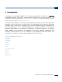
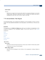
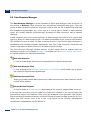
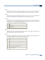
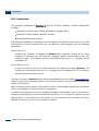
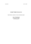
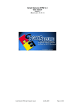
2 Reliance Design Development Environment
The Reliance Design development environment is a program designed for creating and
editing visualization projects. Its user interface consists of several windows. The main window
contains the main menu, toolbars, and the Component Palette. Other windows are the
Component Manager, Window Manager, Layer Manager, Visual Linking, and Information
Window. They can be easily shown and hidden. Each visualization window matches up with a
separate design window. These windows can be managed through the Window Manager.
Reliance 4 Design - Air-conditioning Demo
Context-sensitive help is implemented in the development environment. After selecting a
control and pressing the F1 key, the corresponding help topic is displayed.
Introduction
Main Menu
Reliance 4 – Development Environment
8
Tool Windows
Setting Up the Development Environment
Visualization Project
Components
Managers
Standard Dialog Boxes
Appendices
Reliance 4 – Development Environment
Introduction
2.1 Introduction
Hardware and Software Requirements
The software modules of the Reliance SCADA/HMI system (with the exception of Reliance
Web Client, Reliance Mobile Client, and Reliance Smart Client) can be run on MS Windows
2000, Windows XP, Windows XP Embedded, Windows Vista, Windows 7, Windows 8, Windows
Server 2000, Windows Server 2003, Windows Server 2008, and Windows Server 2008 R2.
Reliance Web Client can be run on all operating systems on condition that the Java Runtime
Environment (JRE 6.0 and higher) is installed on the computer, Reliance Mobile Client is
intended to be run on Windows CE/Windows Mobile and .NET Compact Framework 2.0, and
Reliance Smart Client can run on any Web browser supporting HTML5 and the jQuery Mobile
JavaScript framework.
To create or edit visualization projects, your computer must meet the following requirements:
processor with a clock rate of 2 GHz, 512 MB RAM, screen resolution 1024×768 with color
depth of 24 or 32 bits, MS Windows XP, Windows 7, or Windows Vista. The complete
installation of the development environment including the graphics library and runtime
software requires approx. 400 MB of free hard disk space. Reliance Add-On Pack, which
contains the installers of software tools and third-party drivers, requires an additional 1 GB of
free space.
Starting the Development Environment
The Reliance Design development environment can be started by using a shortcut in the Start
menu or on the Windows desktop. The shortcut allows you to run the executable file
R_Design.exe located in the main directory of the Reliance SCADA/HMI system.
At the first start of the development environment, a dialog is displayed to find out whether
files with an .rp4extension (main Reliance 4 project files) should be associated with the
Reliance Design program. This allows for opening these files automatically without having to
run the program in advance. The association of the .rp4files can also be done later using
the Environment Options dialog (Environment > File Types).
Upon association, the files with an .rp4 extension are marked as Reliance Proj ect and they
are assigned a specific icon. Thus, for example, a visualization project can be opened by
double-clicking on the .rp4 file in the visualization project directory.
Reliance 4 – Development Environment
9
10
Introduction
Whenever you start the development environment, the availability of new versions of the
Reliance SCADA/HMI system is being checked. The program connects to the www.reliance.cz
server and users are notified of new versions, if they are available. Checking for new versions
of Reliance can be enabled/disabled using the Environment Options dialog (Environment >
Update).
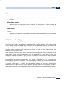
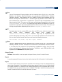
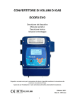
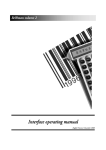
Welcome Window
This window will appear whenever you start the Reliance Design program. The window
contains the following commands: Create New Proj ect, Open Proj ect, Open Recent Proj ect,
Show Help, Show Tutorial, and Reliance Website.
The Welcome window can also be invoked by using the Help > Show 'Welcome' Window
command at any time during working with the development environment.
Reliance 4 – Development Environment
Reliance Main Features
2.2 Reliance Main Features
End User-Intended Features
Systems Integrator-Intended Features
2.2.1 End User-Intended Features
The benefits of using the Reliance SCADA/HMI system for end users, what and how to use
it
Communication with Control Systems
Displaying Data as Trends
Data Overviews
Displaying Data as Mimic Diagrams
Logging Data
Controlling the Process
Alarms and Events
Multimedia
Multilanguage Project Support
User Profiles and Rights
Postmort
Built-in Web Server
Thin Clients
Receiving/Sending Text and Email Messages
System of Notes
Client-Server Architecture
Information Systems Interconnection
Reliance 4 – Development Environment
11
12
Reliance Main Features
2.2.1.1 Communication with Control Systems
Communication with control systems (PLCs, telemetry systems, OPC, native drivers,
Device Manager, tags, CoDeSys import)
The main function of SCADA systems, including the Reliance SCADA/HMI system, is to
acquire data from subsystems (PLCs, telemetry systems, etc.). Reliance allows for reading/
writing data in different formats from/to communication drivers (native drivers, OPC and DDE
servers).
In most cases, each subsystem (connected HW, PLC) corresponds to an object of type device
defined within a visualization project. Devices can only be defined via the Device Manager.
Within each device, you can define tags of different types. The list of tags can be easily
imported from CoDeSys.
The basic properties for connecting to a subsystem can be configured directly from the Device
Manager. To configure the properties of the communication drivers, use the Communication
Driver Manager.
2.2.1.2 Displaying Data as Trends
Displaying data as trends (chart, real-time trend, real-time chart, trends in FastReport,
trend configuration at runtime)
Quantities acquired from control systems can be easily displayed as trends and charts. The
simplest form of chart within the Reliance SCADA/HMI system is represented by the RealTime Trend component. Trend series are based directly on tags and defined via the Real-Time
Trend Manager. The Real-Time Chart component can be used to create a common chart
(when using the Real-Time Trend component, the horizontal axis always represents time).
Reliance also allows you to manage historical trends to display historical data. Trends can be
defined via the Trend Manager; their series are based on data table fields. Trends can be
displayed via the trend viewer. Every user can configure the appearance of a trend. The Trend
Manager can also be accessible to the user during runtime. An unlimited number of trends
with any number of series can be defined within a visualization project.
Reliance 4 – Development Environment
Reliance Main Features
Trends can also be displayed in custom reports of type FastReport. To display historical data
of a single tag, a tag trend is available. A tag trend can be displayed by choosing the Show
Trend command from the popup menu of a Display component placed in a visualization
window. A tag trend is only available if the tag displayed by the component is stored in a data
table.
2.2.1.3 Data Overviews
Data overviews (reports, tables, data tree, custom reports, report configuration at
runtime, filters, PDF, HTML)
In Reliance, data can also be displayed as tables and reports. A Data Grid component placed
in a visualization window can be used to display the current value of an array-type tag. To
display the current value of a single tag, use the Data Tree component.
Reliance allows you to manage historical reports to display historical data as text. Reports
can be displayed at runtime via the report viewer. They can be defined via the Report
Manager. The manager can also be accessible to the user during runtime. Individual report
columns are based on data table fields.
Tag values can be used to build a user-readable output using custom reports. Custom reports
are based on static templates where text, graphic elements, or special character strings can
be included. The special strings are used to mark the place where the real-time value of a tag
should occur in the template when generating a report. Custom reports of type FastReport
allows for inserting, for example, trends and tables based on current and historical data.
2.2.1.4 Displaying Data as Mimic Diagrams
Displaying data as mimic diagrams (screens, windows, window switching, Component
Palette, properties)
Reliance 4 – Development Environment
13
14
Reliance Main Features
To visualize an industrial process and display its data, a vast range of graphical objects
(components) are available to be placed into screens (visualization windows). An ordinary
project contains several visualization windows with components between which you can
switch using buttons. In many cases, buttons used for switching between windows are located
in a separate window of type tray at the edge of the monitor. On the Display page of the
respective computer's properties (in the Proj ect Structure Manager), you can specify the
visualization window to appear as the first window after project startup.
The Component Palette contains a group of standard components (Display, Button, Text,
Active Text, Picture, Active Picture, Check Box, Track Bar, etc.). There are also several other
components, such as Data Tree, Data Grid, Real-Time Trend, or Real-Time Chart. In addition,
the Component Palette contains plenty of special components intended for devices of
particular companies (Teco, Johnson Controls, Sauter, Control, IP Cameras).
To easily configure the component properties, invoke the respective component's property
editor by double-clicking the left mouse button on the component area. To make multiple
changes to the properties, you can also use the Component Manager. Many of the properties
can be linked to tags defined within the visualization project, which allows you to change the
tags' value at runtime using, for example, scripts.
2.2.1.5 Logging Data
Logging data (data tables, SQL, dBASE, Paradox)
Real-time data can be sampled and archive files can thus be created. The Reliance SCADA/
HMI system supports logging data to a file-based data table - dBASE and Paradox (used in the
past) - or to a relational database of type SQL (Microsoft SQL Server). A group of tags is logged
within a data table. Data tables and their properties (e.g., sampling interval, interval of logging
data to a physical table, or interval of creating archive files) can be defined via the Data Table
Manager.
Historical data can be easily displayed as trends and reports.
2.2.1.6 Controlling the Process
Controlling the process (displays, recipes, time programs, level fill picture)
Reliance 4 – Development Environment
Reliance Main Features
In addition to displaying data loaded from the connected devices (PLCs), the Reliance
SCADA/HMI system allows for writing data to the devices. To change tag values (i.e., to
control the visualized industrial process), the following components can be used: Edit Box,
Check Box, Track Bar, Display, etc. You can also use scripts to change tag values
automatically.
To control the process, recipes can be used, too. A recipe is a group of tags whose real-time
values can anytime be stored to a disk file and then loaded from the file. Recipes can be
defined via the Recipe Manager.
All the runtime software programs but Reliance 4 View ("view-only" software) allow you to
control the visualized industrial process.
2.2.1.7 Alarms and Events
Alarms/events (generation, acknowledgment, various databases, viewers, alarm/event
panel)
The Reliance SCADA/HMI system allows the user to be notified of errors by alarms/events.
An alarm can be, for example, generated if the value of a tag lies outside the specified limits.
Alarms/events can be defined via the Device Manager within the device whose tags are
linked to the respective alarm/event. An alarm/event can be linked to a tag change and thus
controlled, for example, from a script.
Alarms/events can be viewed in the runtime environment (and in thin clients) via two viewers.
Those alarms/events which still persist or require acknowledgment by the operator and
system messages can be displayed via the viewer of current alarms/events. The viewer
window can be displayed automatically when an alarm/event is generated. The Reliance
SCADA/HMI system allows displaying current alarms/events on a single line at the bottom of
the runtime software’s main window (alarm/event panel).
All alarms/events (active, inactive, acknowledged, unacknowledged) can be displayed via the
viewer of historical alarms/events. Alarms/events can be stored in a file-based (BDE) or SQLbased database. The way archive files are created, interval of creating archive files, and many
other properties can be configured via the Proj ect Options dialog.
Reliance 4 – Development Environment
15
16
Reliance Main Features
2.2.1.8 Multimedia
Multimedia (sounds, video, IP cameras, ActiveX, animation)
The Reliance SCADA/HMI system allows you to use multimedia. Animation (allows for
animating a sequence of static pictures), Media Player, Internet Explorer, and other
components can be placed into visualization windows. Other applications can be inserted via
the ActiveX Container component. Reliance also supports using Axis and Vivotek IP cameras.
Sounds can be played when alarms/events are generated, end, or are active. They can be
defined via the Proj ect Options dialog.
2.2.1.9 Multilanguage Project Support
Support for multilanguage projects (Unicode, String Manager, switching between
languages during runtime, aliases)
The Reliance SCADA/HMI system allows you to easily create multilanguage projects. The
operator can switch between languages directly in the runtime environment or thin clients. As
Unicode is supported by Reliance, the project and program language can be independently
switched during runtime.
The program language is the language of the GUI (main menu, viewers of alarms/events,
trends, managers, etc.). At runtime, you can choose, for example, from the following
languages: English, Russian, German, and Czech.
The proj ect language is the language of most project-defined text strings. They are, for
example, text strings displayed by components (Button, Text, Check Box, etc.), alarm/event
text strings, names of trend series, and names of report columns. The language in which the
visualization project will be accessible depends only on the author's decision. Visualization
projects are usually designed for one language. Subsequently, other languages can be added
via the Proj ect Options dialog and the String Manager.
Reliance 4 – Development Environment
Reliance Main Features
2.2.1.10 User Profiles and Rights
User profiles and rights (profiles, settings, access restrictions, user administration,
biometric data)
Every user can log on to Reliance with his/her user name and password. Subsequently, any
changes made to the settings of trends and reports are stored in a user profile so that they
can be used when this user next time logs on to the program. A new user can be defined via
the User Manager which is accessible at both design-time and runtime. At runtime, however,
the manager is accessible only to those who have sufficient access rights.
Every user can select a set of access rights. There are 30 access rights available (defined via
the User Manager). Access rights allow you to control the access to specific operations. For
example, if an access right is selected when defining a window, only those users with this
right can access the window.
In the Reliance SCADA/HMI system, a BioLogon fingerprint reader can be used to verify the
user's identity.
2.2.1.11 Postmort
Postmort (replaying the controlled process, analyzing the cause of a failure)
The Postmort function is designed for recording changes in process data of the controlled
process on a real-time basis into special data files. Thus, for example, it is possible to analyze
the cause of a technology failure. To activate Postmort, bring up the Proj ect Structure
Manager and activate the Record postmort property on the Postmort page of the selected
computer (here, you can also specify the number of days recorded).
Postmort records can be played via the Postmort Record Player. When you start replaying the
records, all tags' values are loaded from an archive file, not from devices. Due to the fact that
real-time data is not available when replaying Postmort records, it is highly recommended to
use a different computer for this activity.
Reliance 4 – Development Environment
17
18
Reliance Main Features
2.2.1.12 Built-in Web Server
Built-in Web server (tag values, data overviews, alarms/events displayed as Web pages)
The programs designed for data sharing, i.e., Reliance Control Server and Reliance Server,
contain a built-in Web server. The user can log on to the server via a common Web browser
and, thus, be informed of tag values, generate reports and custom reports, or run the mobile
or Web client.
Similarly to accessing components defined within a visualization project, access rights can be
required to access the Web server.
2.2.1.13 Thin Clients
Thin clients (one visualization project, visualization on various platforms, Web client,
mobile client, PDA)
Reliance's thin clients are designed for running visualization applications on remote devices
connected to the Internet (e.g., computers, cell phones, PDAs). Both clients use one of
Reliance's data servers (Reliance Control Server or Reliance Server) as the data source. They
only have some of the features of the runtime software. Although they allow for controlling the
visualized industrial process, some features are not available (e.g., recipes, ActiveX, some
time programs).
Reliance Web Client is a multi-platform application designed to run on devices where the Java
Runtime Environment (JRE 6.0 and higher) is installed. The Web client can run as an applet or
as a stand-alone application. Usually, no special configuration (project computer) is needed
for the Web client. When starting the Web client, it is always checked whether a new version
of the project file is available. If so, the new version is started automatically.
Reliance Mobile Client is an application intended to be run on Windows CE/Windows Mobile.
Because these devices usually have a smaller screen resolution, it is generally necessary to
create a special configuration intended for mobile devices only.
Prior to using a thin client, the project must be exported using the Export Proj ect for Remote
Users Wizard.
Reliance 4 – Development Environment
Reliance Main Features
2.2.1.14 Receiving/Sending Text and Email Messages
Receiving and sending text messages, sending email messages
The Reliance SCADA/HMI system allows sending and receiving text messages via a GSM
device (modem). The settings related to sending text messages can be configured via the
Proj ect Structure Manager and data communication is realized via scripts. Sending and
receiving text messages is demonstrated in the Demos/ SMS example which is supplied
together with Reliance.
Sending email messages can be done in a similar way. The settings related to sending email
messages (e.g., SMTP server and sender details) can be configured via the Proj ect Structure
Manager (on the E-mail page of the respective computer). Emails can only be sent from
scripts. Sending email messages is demonstrated in the Scripts/ SendEmail example. This
project as well as other examples are available in the <Reliance>\Examples directory.
2.2.1.15 System of Notes
System of notes (notes related to alarms/events, windows, object comments, labels)
Within Reliance, there are many places where you can make notes or comments. Every
object (component, trend, table, tag, etc.) contains properties named Comment and
Description. Components also allow you to display bubble help (help hints).
Once you log on to the runtime environment, you can leave a comment related to visualization
windows or alarms/events for your colleague, employee, etc. To delete notes, access rights
can be required in the same way as for alarm/event acknowledgment.
2.2.1.16 Client-Server Architecture
Client-server architecture, redundancy, centralization, decentralization
Reliance 4 – Development Environment
19
20
Reliance Main Features
The Reliance SCADA/HMI system has a client-server architecture. In most cases, the socalled data server (Reliance Server or Reliance Control Server) is the central module. The
data server communicates with a PLC through a serial cable, LAN, OPC server, etc. The
device's data can also be visualized using clients (Reliance Control, Reliance View, Web Client
, Mobile Client). The topology of the system can be defined via the Proj ect Structure Manager
(each computer defined via the manager usually corresponds to a single real workplace
computer).
To make the system more resistant to failures, data server redundancy can be provided. In
such a configuration, if a data server failure occurs, the runtime software on the client
computer automatically attempts to connect to the other data server. PLC redundancy can
also be provided. Primarily, communication can be carried out, for example, through a LAN. In
the event of a communication failure, it can be redirected using a serial cable.
2.2.1.17 Information Systems Interconnection
Exchanging data with existing enterprise information and SCADA systems (OPC server,
MES, ERP, etc.)
The Reliance SCADA/HMI system can exchange data with external applications and existing
enterprise information systems. This can be done, for example, via the OPC or DDE protocol, a
file, or the COM interface. For more information on how to exchange data with third-party
applications, read the Data Exchange Methods manual.
2.2.2 Systems Integrator-Intended Features
The benefits of using the Reliance SCADA/HMI system for systems integrators, how it
facilitates application development, what is hidden to the customer
Script Support
Graphics and Pictures
Quick Creation of Links to Tags
Open Format
Reuse of Function Units
Diagnostics and Navigation
Reliance 4 – Development Environment
Reliance Main Features
Multiple Property Changes
Window Layers
Actions Invoked by Components
Backward Compatibility
Easy Topology Extension
Automatic Project Update
Virtual and System Tags
Quick Component Handling
Project Backup During Development
Project Security
Clear Licensing
2.2.2.1 Script Support
Support for scripts (VBScript, functionality enhancement, adjusting to less usual requests)
Although Reliance is designed to be handled with the maximum possible speed and simplicity
without need for programming, more functions can be achieved by using the VBScript
language. Scripts can be created via the Script Manager. Usually, scripts get executed
periodically, but they can also get executed when a certain event occurs (e.g., when a button
or a keyboard shortcut is pressed, alarm/event). Scripts can be used to perform basic
operations (calculations or constant initialization), more complex operations (sending text
messages or working with databases), but also to work with object-oriented programming and
perform many other operations.
2.2.2.2 Graphics and Pictures
Graphics and pictures (central picture management, support for transparency, 32-bit color
depth, various formats)
Reliance 4 – Development Environment
21
22
Reliance Main Features
One of Reliance's main advantages is that you can easily develop a good-looking application.
The system supports both vector and raster pictures. As pictures can be easily edited in
common graphic editors, you can benefit from the main advantages when using raster
pictures (bitmaps). Pictures in Reliance can be shown in their natural colors (16.7 million
colors). All common formats are supported (BMP, JPG, PNG, etc.). Pictures (or photographs)
can represent the background of a visualization window, production machines, buttons and
switches, animations, etc.
All pictures to be used in a visualization project must be first imported to the project's picture
database via the Picture Manager. They are copied (in the same format) to the appropriate
folder in the project's directory structure. Also, they can be renamed. A picture can be
displayed on a window's background or via the following components: Picture, Active Picture,
Animation, and Level Fill Picture. It can also be used to modify the appearance of the Button,
Gauge, Progress Bar, and Bevel components.
In the Reliance SCADA/HMI system, vector graphics is represented by pictures in the *.wmf/
emf format which are imported and used in the same way as raster pictures. To draw basic
shapes, you can use vector components, such as Bar, Circle, Ellipse, or Grid. Vector graphics
can also be used to draw most components (Pipe, Progress Bar, Scale, Clock, Real-Time
Trend, Real-Time Chart, Bevel, etc.).
2.2.2.3 Quick Creation of Links to Tags
Quick linking of tags to components (visual linking)
Most active components are controlled by a main tag. Their size, position, and visibility can
also be controlled dynamically using tags. To specify the link to a tag, bring up the selected
component's Properties dialog box and choose the desired tag via the Select Tag dialog box. If
multiple components are to be linked to tags, the Visual Linking tool window can be used. To
specify the link to the tag whose value is to be control the desired property of the respective
component, simply drag and drop the tag from the Visual Linking window onto the
component.
Reliance 4 – Development Environment
Reliance Main Features
2.2.2.4 Open Format
Open format (scripts in TXT, windows in XML, pictures in the original format, others in RDT
tables, export to CSV)
A Reliance visualization project is stored on disk within a specific directory structure. The
project itself consists of files in different, mainly open formats. Pictures are stored in the
original format, the window structure (component layout) is stored in XML files, scripts' code is
stored in a text file. Many other objects are stored in files in the RDT format (Reliance Data
Table). These data tables can be edited via the RDT File Editor supplied together with
Reliance).
Objects can also be exported from the Reliance Design development environment as plain
text (in the CSV format). They can then, for example, be edited and imported back to the same
or another visualization project. Data (of reports, alarms/events, trends, and custom reports)
can also be exported from the runtime environment to CSV.
2.2.2.5 Reuse of Function Units
Reusing function blocks (windows on different computers, window templates, structured
tags)
In Reliance, reusing objects and function blocks is supported at different levels. At the top
level, you can repeatedly use a computer (the same computer configuration can be used for
an unlimited number of client instances of the runtime software or Web clients). Within a
visualization project, you can define objects, such as windows, scripts, reports, or trends.
Subsequently, any combination of these objects can be connected to the project computers,
which allows you to create different configurations for different workplaces.
At the level of visualization windows, you can group multiple components using a window
template and embed this template into different windows through a Container component.
Tags can be grouped via the Data Structure Manager and the created structured tag can be
linked to a Container component. Within visualization windows, you can lock the relative
position of the selected components by choosing the Group command.
Reliance 4 – Development Environment
23
24
Reliance Main Features
2.2.2.6 Diagnostics and Navigation
Project diagnostics, navigation, finding object usages
By default, the Reliance Design development environment uses a tool named Proj ect
Diagnostics. It is intended for checking all objects within a visualization project and detecting
issues. It also allows you to find unused objects. To make the diagnostics faster or ignore
some issues, you can choose project scopes to diagnose.
Another useful feature is that you can find links to selected objects in specified parts of the
project. For this purpose, the Find Obj ect Usages command should be chosen from the
selected object's popup menu. To search for an object by name, choose the Find Obj ect
command from the popup menu.
2.2.2.7 Multiple Property Changes
Multiple property changes (window, component, and manager properties)
In the Reliance Design development environment, there are several tools which allow you to
change multiple properties at a time. To change the properties of multiple components, the
Component Manager can be used. After selecting components, the manager displays the list
of all properties you can change at a time (the intersection of the properties is displayed). The
Component Manager allows you to change window properties, too.
Most managers allow changing the properties of multiple objects. First, select several objects
(tags, reports, etc.). Then, change the properties using pages in the right pane.
For the purpose of changing multiple properties, the Substitute components' links to tags
property can also be used. This property can be activated via the Duplicate Window dialog. It
can be used, for example, when several similar windows should be defined within a project to
visualize data of several similar devices.
A useful way to change multiple properties can be provided by the function Text replacement
of object properties. After selecting, for example, a component group or several windows,
bring up the Replace Obj ect Properties Wizard from the popup menu. The wizard lets you
replace the properties of the currently selected objects by entering the text to be replaced and
the new text.
Reliance 4 – Development Environment
Reliance Main Features
2.2.2.8 Window Layers
Window layers (grouping components within a layer)
The Reliance SCADA/HMI system contains a system of layers which allows grouping
components of a similar type. To make designing a visualization window clearer, you can
move a component to a different layer via the Layer Manager. To avoid unintentionally
changing the position and size of all the components located on a layer, the components can
be locked. Each visualization window defined within a project has 16 layers.
2.2.2.9 Actions Invoked by Components
Performing actions related to various events (displaying Web pages, program startup,
function activation)
In the Reliance SCADA/HMI system, actions are intended for easily executing one-shot
commands. Actions can be performed after clicking or double-clicking individual mouse
buttons on the area of most components. They can be defined via the Action Manager.
Displaying trends, reports, or the Log On User dialog are the most often used actions. It is
helpful to use actions, for example, when a visualization project runs without displaying the
main menu, i.e., most of the menu's commands are accessible via actions. You can choose
from about 40 actions. After defining an action, it can be chosen on the Scripts/ Actions page
of the selected component's Properties dialog box. The Data Tree component allows you to
connect an action to individual nodes and cells.
2.2.2.10 Backward Compatibility
Backward compatibility and upgrading older versions of Reliance (regular updates,
converting to a newer version)
Reliance 4 – Development Environment
25
26
Reliance Main Features
While the development of Reliance is in progress, new features are added to fix potential
bugs. Therefore, it is recommended to use the latest version of the system. Any upgrades
within the current major version (Reliance 4 or Reliance 3) are free of charge. Also, there is
no problem with loading existing projects in a newer version – the system is backwardcompatible. However, after editing a project in a newer version of Reliance Design, it may not
be possible to use the project in an older version of the runtime software (the system is not
forward-compatible).
There is also backward compatibility between adjacent major versions. For example, a
Reliance 3 visualization project can be run in Reliance 4 after the original project is
converted to the Reliance 4 format by Reliance 3 to 4 Proj ect Converter. In this case, license
upgrades are charged.
2.2.2.11 Easy Topology Extension
Configuring project computers (topology extension, the same project on every computer,
identification)
Creating more complex Reliance applications is based on the client-server architecture. A
simple network application may consist of a data server (e.g., Reliance Control Server) and a
client (e.g., Reliance Control). The data server communicates directly with PLC devices, logs
historical data, and provides clients with data. Both server and client computers can be
configured via the Proj ect Structure Manager. The term Computer is a common name for
such a configuration. When configuring the server computer, its IP address must be specified
so that the client computer, upon its startup, knows with which computer to establish
communication. Server connections can also be defined via the Proj ect Structure Manager
(see the Network Applications example projects). All computers defined within the Proj ect
Structure Manager must contain the same project. Network applications can be developed
via the Enterprise version of the development environment (the Desktop version is intended
for creating applications with 1 computer).
To add another client to your application, simply install the Reliance SCADA/HMI system on
another computer and run the visualization project in the same way as on the original client
computer. Data servers can be added to your application via the Proj ect Structure Manager
where the needed server connections should also be defined. Data servers can be configured
so that they provide redundancy and load balancing or load data from different places (see
the Network Applications example projects).
Reliance 4 – Development Environment
Reliance Main Features
Reliance Server, which has no graphical interface and runs as a Windows Service, can
operate on computers which are only used as data servers. To extend the application
topology, thin clients can also be used.
2.2.2.12 Automatic Project Update
Automatically updating a project from the specified directory
For smooth operation, each computer running Reliance's runtime software must have the
current version of the project files installed. To avoid the need to manually copy the project to
all computers each time it is updated, you can update the project automatically. If this
function is active, the availability of a new version of the project is checked each time the
project is started. The project can be automatically updated from the specified directory
(usually within the computer network). This function can be used, for example, together with
the program designed for the remote control of Reliance's runtime software (Reliance
Remote Control Center) which allows, among other things, restarting a project from remote
locations.
The automatic project update settings can also be configured for the thin clients (Reliance
Web Client and Reliance Mobile Client). The availability of a new version of the project is
checked each time a thin client is run. The new version is then downloaded. A program
named Updater can be used to download updates for the mobile client.
2.2.2.13 Virtual and System Tags
Virtual and system tags
In Reliance, tags can be divided into physical and internal. A physical tag is stored directly in
the memory of a physical device (PLC). Its value is synchronized with the value of the tag
stored on the computer running the runtime software.
The value of an internal tag is only stored in the memory of the computer. Tags defined within
the System device are a special type of internal tag. These tags' values are not intended to be
transferred between instances of the runtime software. For this reason, they do not affect the
number of data points, i.e., they are free of charge. Internal tags which do affect the number
of data points and whose values can be transferred between instances of the runtime
software can be defined within virtual devices.
Reliance 4 – Development Environment
27
28
Reliance Main Features
2.2.2.14 Quick Component Handling
Handling components (grouping, adjusting the size, aligning, guidelines, transformation,
grid, lock)
At design-time, there are many useful tools available for working with components placed into
a visualization window. The grid is very helpful when positioning components. The commands
for editing components are accessible from the Edit menu. After selecting a single or multiple
components, you can, for example, adjust their width, center them vertically/horizontally, or
equally space them vertically/horizontally.
Another useful feature is transformation. The Transform command can be used to resize or
move the currently selected components in a given ratio. This can be helpful, for example, if it
is necessary to adjust an already designed visualization window to a new size. To avoid
accidental changes, you can lock the active window to prevent the position and size of the
components from being changed.
You can also decide whether to display guidelines when changing the position and size of a
component with the mouse. These lines indicate the selected component's edges as they
meet the edges of other components.
2.2.2.15 Project Backup During Development
Backing up a project at design-time (restoring the project from the backup file, choosing
the backup file name)
At design-time, it is beneficial to periodically back up your project so that you can recover data
from an earlier time. In the Reliance SCADA/HMI system, visualization projects can be easily
backed up through a tool named Proj ect Backup accessible from the Proj ect menu. The
Backup Proj ect Wizard allows you to back up your visualization project as a file in the ZIP
format which is, by default, stored on disk. When choosing the backup file name, its time
stamp can also be specified. This makes the orientation in the backup history easier and
allows creating frequent backups. To recover data from the backup file, choose the Restore
Proj ect from Backup command from the File menu.
The tool for creating project backups can also be used to easily transfer a visualization project
to other computers. You can specify project parts to be backed up (e.g., including data).
Reliance 4 – Development Environment
Reliance Main Features
2.2.2.16 Project Security
Project security (safe communication, project files encryption)
To prevent the end user from editing a visualization project, a password should be used. This
password will then encrypt your project. It will be required every time the project is being
opened with Reliance Design, it will not be required at runtime.
By default, network communication between instances of the runtime software is encrypted
to avoid monitoring by a third party. Communication between a data server and a thin client is
also encrypted by default.
2.2.2.17 Clear Licensing
Clear licensing (based on the number of I/O tags – data points, license upgrade whose
price is determined as the difference between the price of the new and the original
license, software keys for small applications, hardware keys for large applications,
licenses with an unlimited number of data points, time-limited licenses, trial version free
of charge)
The number of data points is the main factor affecting the price of a license. The number of
data points depends on the number and data type of tags defined within a visualization
project. The number of tags defined within the System device (i.e., private internal tags) do
not affect the price.
The license is stored in a license key of which there are two types: software key and hardware
key. While a software key can only be used on the computer it is designed for, a hardware key
is portable between computers and is intended for licenses with 250 and more data points.
An already purchased license can be easily upgraded, only the difference between the price
of the new and the original license has to be paid off. The upgrade process can take up to
several hours (you'll be sent a license file which has to be stored into the current hardware
key via License Key Utility). In the event of emergency or for testing purposes, we can also
provide you with temporary licenses (both SW and HW).
If you run any software module without a license key, it acts as a trial version. In this case, the
number of data points is limited to 25. If you happen to run a project requiring more data
points than the license allows, no other tags are loaded. This fact is highlighted in the current
alarm/event viewer.
Reliance 4 – Development Environment
29
30
Reliance 4 – Development Environment
31
3 Main Menu
The main menu is the menu bar located in the development environment's main window. The
most frequently used commands are also available in the toolbars located in the main
window. Some commands can be executed using a particular keyboard shortcut. Keyboard
shortcuts can be configured by the user (see Keyboard Shortcuts).
File Menu
Edit Menu
View Menu
Managers Menu
Project Menu
Tools Menu
Window Menu
Help Menu
Reliance 4 – Development Environment
32
File Menu
3.1 File Menu
The File menu contains commands for creating, opening and closing visualization projects
and commands for creating and saving visualization windows. The menu also contains a list
of most recently opened projects, which allows for quick selection of a project. Some
commands are available in the Welcome window, too.
New Project
Brings up the Create New Project Wizard.
Open Project (Ctrl+O)
Displays the dialog box for selecting an existing visualization project. Here, it is possible
to select files with an .rp4 extension (main project file in the Reliance 4 format) or with
a .prj extension (main project file in the Reliance 3 format). When selecting a file in
the Reliance 4 format, the project is opened and loaded. When selecting a file in the
Reliance 3 format, the Project Conversion Wizard is brought up. The wizard allows
converting the project into the Reliance 4 format.
Restore Project from Backup
Brings up the Restore Project from Backup Wizard.
Close Project
Closes the active project. If any modifications have been made, the user is prompted to
save the changes before closing the project.
New Window
Brings up the Create New Window Wizard.
New Window Template
Brings up the Create New Window Template Wizard.
Save Window (Ctrl+S)
Saves changes in the active window.
Reliance 4 – Development Environment
File Menu
Save All Windows
Saves changes in all open windows.
Close Window (Ctrl+F4)
Closes the active window and releases it from memory.
Close All Windows
Closes all active windows and releases them from memory.
Exit
Exits the program. If any modifications have been made to the open project without being
saved, the user is prompted to save the changes before exiting the program.
Reliance 4 – Development Environment
33
34
Edit Menu
3.2 Edit Menu
The Edit menu contains a set of commands for editing graphical objects (components) in the
active window. They are commands intended for basic editing operations (Copy, Duplicate,
Delete, etc.), organizing components (Group, Lock, etc.), locating components (Alignment,
Center, etc.), resizing (Shrink to Smallest, Grow to Largest, etc.), changing the Z-order of
components, transforming, rotating and aligning components to the grid, etc.
The commands for editing components use the internal clipboard, not the system one. As a
result, the contents of the clipboard can only be used within one instance of Reliance Design.
If you need to copy a component to another project, you can use the Export command in the
Window Manager and then import the window into another project using the Import command
in the Window Manager.
Undo (Ctrl+Z)
Reverses the last action taken and thus restores the components to their previous state.
Up to 100 actions can be undone using the Undo command. To set the number of
changes, use the Environment Options dialog (Environment > Visualization Windows).
The change history allows for storing the operations of adding a component (including
pasting it from the clipboard), deleting, sizing, rotating, and changing the position of a
component.
Redo (Shift+Ctrl+Z)
Repeats the last action taken.
Cut (Ctrl+X)
Removes the currently selected components from the window and places it on the
clipboard.
Copy (Ctrl+C)
Places a copy of the currently selected components on the clipboard.
Duplicate (Ctrl+D)
Copies the currently selected components and places them into the same window
(horizontally and vertically shifted by 8 pixels).
Reliance 4 – Development Environment
Edit Menu
Paste (Ctrl+V)
Places the contents of the clipboard into the active window.
Delete (Del)
Deletes the currently selected components from the active window.
Select All (Ctrl+A)
Selects all the components in the active window.
Unselect All (Esc)
Unselects all the currently selected components in the active window.
Select Next (Tab)
Selects the next component in the Z-order (ordering of overlapping components) after the
currently selected component.
Select Previous (Shift+Tab)
Selects the previous component in the Z-order before the currently selected component.
Group (Ctrl+G)
Groups the currently selected components. You can move the component group as if it
were one object. The position and size of the components in the group remain
unchanged. The highlight style of the selected component group is different in color from
the one of multiple selected individual components.
Ungroup (Ctrl+U)
Breaks the currently selected group into individual components.
Reliance 4 – Development Environment
35
36
Edit Menu
Alignment Menu
Left
Aligns the left edge of each selected component with the left edge of the leftmost
selected component.
Right
Aligns the right edge of each selected component with the right edge of the rightmost
selected component.
Top
Aligns the top edge of each selected component with the top edge of the topmost
selected component.
Bottom
Aligns the bottom edge of each selected component with the bottom edge of the
bottommost selected component.
Center Vertically
Aligns the center of each selected component with the vertical centerline of the
currently selected components. The vertical centerline runs midway between the left
and right edge of the selected components.
Center Horizontally
Aligns the center of each selected component with the horizontal centerline of the
currently selected components. The horizontal centerline runs midway between the
top and bottom edge of the selected components.
Space Equally, Vertically
Equally spaces the currently selected components vertically keeping the same
distances between the centers of the components.
Space Equally, Horizontally
Equally spaces the currently selected components horizontally keeping the same
distances between the centers of the components.
Reliance 4 – Development Environment
Edit Menu
Size Menu
Shrink to Smallest, Horizontally
Adjusts the width of the currently selected components to the smallest selected
component.
Grow to Largest, Horizontally
Adjusts the width of the currently selected components to the largest selected
component.
Shrink to Smallest, Vertically
Adjusts the height of the currently selected components to the smallest selected
component.
Grow to Largest, Vertically
Adjusts the height of the currently selected components to the largest selected
component.
Order Menu
Bring to Front (Shift+PgUp)
Moves the currently selected components to the front in the Z-order on top of all
other components. The Z-order is designed to order overlapping components within
a window. The most recently added component or the one on which the Bring to Front
command was last applied is to be ordered last in the Z-order and therefore not
overlapped by other components.
Bring Forward (Ctrl+PgUp)
Moves the currently selected component forward by one level in the Z-order.
Send to Back (Shift+PgDn)
Moves the currently selected components to the back in the Z-order beneath all other
components.
Reliance 4 – Development Environment
37
38
Edit Menu
Send Backward (Ctrl+PgDn)
Moves the currently selected component backward by one level in the Z-order.
Transform
Opens the dialog box for relative change of the position and size of the selected
components - Transform. This command, for example, allows you to resize the currently
selected components in a given ratio.
Rotation Mode (Ctrl+R)
Switches the currently selected component to the rotation mode. The rotation mode can
be deactivated by unselecting the component.
Align Position to Grid
Aligns the currently selected component's top left corner to the grid.
Align Size to Grid
Aligns the currently selected component's bottom right corner to the grid according to the
grid spacing.
Lock (Ctrl+L)
Locks the active window to prevent the position and size of the components from being
changed. The highlight style of the selected components in a locked window is different
in color from the one of an unlocked window. To unlock the window, repeat the previous
command.
Component Properties (Alt+Enter)
Opens the dialog box for editing properties of the currently selected component (see
Components).
Reliance 4 – Development Environment
Edit Menu
3.2.1 Transform
Relative change of position and size
X-coordinate, Y-coordinate
Allows for setting position ratios of a component (components).
Width, Height
Allows for setting size ratios of a component (components).
Rotate horizontally by 180°, Rotate vertically by 180°
This option is only used to change the orientation of a Line component (for other
components, it is not active).
Reliance 4 – Development Environment
39
40
View Menu
3.3 View Menu
The View menu allows for showing and hiding tool windows of the development environment.
Component Manager (F11)
Shows or hides the Component Manager window.
Window Manager (F12)
Shows or hides the Window Manager window.
Layer Manager
Shows or hides the Layer Manager window.
Information Window
Shows or hides the Information Window.
Visual Linking
Shows or hides the Visual Linking window.
Reliance 4 – Development Environment
Managers Menu
3.4 Managers Menu
The Managers menu contains commands for showing the managers of visualization projects'
objects.
Data Structure Manager
Brings up the Data Structure Manager.
Device Manager
Brings up the Device Manager.
Communication Driver Manager
Brings up the Communication Driver Manager.
Recipe Manager
Brings up the Recipe Manager.
Data Table Manager
Brings up the Data Table Manager.
Trend Manager
Brings up the Trend Manager.
Real-Time Trend Manager
Brings up the Real-Time Trend Manager.
Report Manager
Brings up the Report Manager.
Custom Report Manager
Brings up the Custom Report Manager.
Reliance 4 – Development Environment
41
42
Managers Menu
String Manager
Brings up the String Manager.
Picture Manager
Brings up the Picture Manager.
Action Manager
Brings up the Action Manager.
Script Manager
Brings up the Script Manager.
User Manager
Brings up the User Manager.
Project Structure Manager
Brings up the Project Structure Manager.
Reliance 4 – Development Environment
Project Menu
3.5 Project Menu
The Proj ect menu contains commands for working with the open visualization project.
Run (F9)
Starts the visualization project in the runtime software specified in the Project Options
dialog box. When the runtime software is started, the development environment will be
minimized to the taskbar. When the runtime software is exited, the development
environment will be restored.
Create Shortcut
Brings up the Create Shortcut to Project dialog box.
Perform Diagnostics
Brings up the Project Diagnostics Wizard.
Backup
Brings up the Backup Project Wizard.
Export for Remote Users
Brings up the Export Project for Remote Users Wizard.
Re-export for Remote Users
Brings up the Export Project for Remote Users Wizard and goes to the final step before
starting the export. The export is based on the settings used during the last export. If no
export has been performed so far, the default settings are used.
Encrypt
Encrypts the project files. All project files will be encrypted except the main file. To
encrypt the project, a password must be entered and then confirmed. In the runtime
software, there is no difference between an encrypted and unencrypted project.
However, the development environment requires a password to open the project.
Reliance 4 – Development Environment
43
44
Project Menu
Decrypt
Decrypts the project.
Information
Brings up the Project Information dialog box. Among other things, this dialog box contains
information on the number of tags and data points.
Options
Brings up the Project Options dialog box.
Reliance 4 – Development Environment
Tools Menu
3.6 Tools Menu
The Tools menu contains commands for setting up the development environment (see
Environment Options). These commands are accessible even if no project is opened.
Configure Toolbars
Brings up the Configure Toolbars dialog box.
Configure Component Palette
Brings up the Configure Component Palette dialog box.
Environment Options
Brings up the Environment Options dialog box.
Reliance 4 – Development Environment
45
46
Window Menu
3.7 Window Menu
The Window menu contains commands for working with visualization windows.
Next (F6)
Activates the next window. It brings the next open window to the foreground (the windows
are ordered in the order they were added to the project). A window is opened if it is
loaded into memory.
Previous (Shift+F6)
Activates the previous window. It brings the previous open window to the foreground.
Open Window List (Alt+0)
Brings up the Open Window List. It allows you to select and activate any window in the
list. A window is opened if it is loaded into memory. A window can be shown and loaded
into memory via the Window Manager. A window stays in memory even if it's hidden (e.g.,
using the standard Close command in the title bar or the standard Alt+F4 keyboard
shortcut).
Properties (Alt+Enter)
Brings up the Window Properties dialog box which allows for setting up the selected
window (window type, loading, appearance, size, access rights, etc.).
Reliance 4 – Development Environment
Help Menu
3.8 Help Menu
The Help menu mainly contains commands for accessing the help system, license
registration, and the Internet resources.
Show 'Welcome' Window
Brings up the Welcome window which contains commands used for the startup of the
development environment.
Contents (F1)
Allows you to access the help system.
Reliance on Internet
Allows you to access the Reliance website (www.reliance.cz).
Check for Updates
Allows you to check for new versions of the Reliance SCADA/HMI system.
License Menu
Activate
Brings up the Activate License Wizard. Every SW key requires activation for
a computer fitted with the Reliance SCADA/HMI system. Detailed activation
instructions are described in the separate document License Activation.
Register
Allows you to register a license. Upon registration, the user's personal information
(name and company) is saved. This information can be found in the About Reliance
4 Design dialog box. The user is prompted to select an *.rlr registration file.
Information
Brings up the License Key Records dialog box. This dialog can also be accessed via
the License Key Utility application which, by default, is located in the Utils directory.
Reliance 4 – Development Environment
47
48
Help Menu
About Reliance 4 Design
Allows you to view information about Reliance Design. This dialog box provides
information about the version, license (serial number, data points), registration,
and operating system. By clicking on the serial number, you can find out how the license
is verified or display information about the connected license key (License Key Records).
Reliance 4 – Development Environment
49
4 Tool Windows
Tool windows are floating, modeless windows designed for working with visualization windows
and components. These windows can be displayed or hidden using commands in the View
menu or particular toolbar buttons. All tool windows can be customized using the following
commands available from the standard local menu:
Large Buttons
Makes the toolbar buttons appear as large.
Small Buttons
Makes the toolbar buttons appear as small.
Transparent
Allows for setting five levels of a tool window's transparency (0%, 20%, 40%, 60%, 80%).
The 0% transparency means that the window is opaque. The set transparency only
applies if the window is not active.
Stay on Top
Makes the tool window always appear on top of the other windows (except for the
windows in the same mode).
The development environment's tool windows include:
Component Manager
Window Manager
Layer Manager
Visual Linking
Information Window
Reliance 4 – Development Environment
50
Component Manager
4.1 Component Manager
The Component Manager is a tool window that allows for a quick and multiple change of
selected components' properties or visualization windows. It also allows you to manage the
list of components in the active visualization window.
The Properties page contains a list of component properties (either a single component's
properties or the intersection of multiple components' properties). The properties can be
sorted alphabetically or divided into groups. If a single component is selected, the properties
of this component are displayed. If multiple components are selected, the page only displays
the properties common to all the selected components (except the component name).
A visualization window and components can only be selected and edited separately (not
simultaneously). The properties can be edited in the second column of a particular row - you
can activate or deactivate them, enter a value or text, or select an item in the combo box or in
the special dialog box which can be displayed when clicking on the ellipsis button (three
periods). To set colors, it is possible to use either the combo box with predefined colors or the
Select Color dialog box which can be displayed by double-clicking in the particular row.
On the Components page, there is a list of components contained in the active window. They
can be sorted by various criteria (Name, Type, Order, Group, and Layer). Components can be
selected by clicking the check box. This action also selects the component in the visualization
window. This also works the other way around. So, if you select a component in the
visualization window, it is also checked in the check box on the Components page. Selecting
components using the Component Manager is especially useful when a component is hidden
by another overlying component and it's therefore impossible to select it with the mouse.
Groups
Determines whether to arrange the properties into groups.
Expand Groups
Expands the properties (including the groups).
Collapse Groups
Collapses the properties (including the groups).
Localized Property Names
Determines whether to display the localized property names (aliases) or the real English
programmatic names.
Reliance 4 – Development Environment
Component Manager
Help for Selected Property
Shows or hides the bottom help panel describing the selected property.
Collection Editor
Some components contain a special property called a collection; it is a list of items of the
same type. Each item has its own properties. To view or edit these items, use the so-called
Collection Editor. An example of a collection is a list of text states (the States property) of the
Active Text component.
Active Text component - States
The Collection Editor allows you to add, delete, and select the items and change their order. If
you select one or more items, the Component Manager will enable you to view and edit their
properties. When you close the Collection Editor, the properties of the selected component
will be displayed again in the Component Manager.
Reliance 4 – Development Environment
51
52
Window Manager
4.2 Window Manager
The Window Manager is a tool window that displays a list of all visualization windows. It is
designed for managing the windows, i.e., it allows you to open/close the windows, add new
windows or remove the windows from a project. The Window Manager is also used to switch
between visualization windows, i.e., activate them.
The visualization windows in the list can be arranged in folders. The state of a visualization
window, whether it is open, i.e., loaded into memory or closed, is indicated by the font style of
the window's name (open - bold font, closed - regular font). Normal and dialog windows which
are not loaded dynamically are indicated in blue (see the Basic page). The items in the list can
be sorted by the Title and Name columns. The item's icon indicates the window's type
(normal, dialog, tray, template).
The status bar displays the ID (identification number) and name of the window currently
selected in the Window Manager. The ID corresponds to the order in which windows are
added to the project.
New Folder (Alt+Ins)
Adds a new folder. Folders make managing multiple windows easier. From the
perspective of hierarchy, folders can only be added on one level.
New Window (Ins)
Brings up the Create New Window Wizard. When the wizard is finished, a new
visualization window is added to the list.
New Window Template
Brings up the Create New Window Template Wizard. When the wizard is finished, a new
window template is added to the list. Window templates are intended to easily reuse
graphic elements in visualization windows.
Open (Enter)
Opens the selected window.
Delete (Del)
Releases the selected window from memory and removes it from the hard disk. The user
is prompted to confirm the action.
Reliance 4 – Development Environment
Window Manager
In addition to the commands contained in the toolbar, the popup menu of the window list also
includes the following commands:
Rename (F2)
Allows you to rename the selected window. This can also be done by clicking on the
already selected name of the window. You can only rename open windows.
Duplicate (Ctrl+D)
Displays the Duplicate Window dialog box which allows you to make a copy of the
currently selected window.
Close
Closes the currently selected windows. The windows are released from memory when
closed. The user is prompted to save any changes that have been made to the windows.
Close All Windows
Closes all open windows.
Find Object (Ctrl+F)
Brings up the Find Object dialog box which allows you to find a window by any part of its
name.
Find Object Usages (Alt+F)
Brings up the Find Object Usages Wizard which will find the objects that reference the
selected window.
Perform Diagnostics
Brings up the Project Diagnostics Wizard which will check the selected windows for
errors.
Replace Object Properties
Brings up the Replace Obj ect Properties Wizard.
Reliance 4 – Development Environment
53
54
Window Manager
Export
Exports the selected window. Due to subsequent import, the object IDs in the exported
file (XML format) are replaced with names.
Import
Imports a window from an XML file. When the import is finished, the window is added to
the project. During the import, the links to objects are resolved by name.
Import Content
Imports components from an XML file into the selected (existing) window. The original
content of the window is removed. During the import, the links to objects are resolved by
name. The command is intended for transferring components between windows from
different projects.
Properties (Ctrl+Enter)
Brings up the Window Properties dialog box which allows for setting up the selected
window (window type, loading, appearance, size, access rights, etc.).
Reliance 4 – Development Environment
Layer Manager
4.3 Layer Manager
The Layer Manager is a tool window that contains a list of the so-called layers of the active
visualization window. The system of layers gives a 'third dimension' to visualization windows.
Each window has 16 layers in which components can be arbitrarily located. Each component
can only be located on one layer. The Layer Manager allows for locking and making layers
(hence the relevant components) visible or hidden. A name can be assigned to each layer.
Visible
Changes the visibility status. If the Visible button is not pressed, all the components
located on the layer are hidden. This makes working with components on other
(displayed) layers easier. The layer visibility can also be set by clicking the check box next
to the item's (layer's) name or by double-clicking the item itself.
Locked
Locks/unlocks the selected layer. If the Locked button is pressed, all the components
located on the layer are locked. Once the components are locked, you cannot move
them.
Rename
Allows you to rename the selected layer. This can also be done by clicking on the already
selected name of the layer.
Warning: A new component (added to a window from the Component Palette) is automatically
added to the layer selected in the Layer Manager. If you want to move a component to
another layer, use the Move to Layer command in the popup menu of the selected
component.
Reliance 4 – Development Environment
55
56
Visual Linking
4.4 Visual Linking
The Visual Linking is a tool window that allows you to quickly link component properties to
tags (the so-called linking). In the toolbar, you can select which component properties should
be controlled by tags after they are linked. It is possible to perform linking for the following
properties:
Main
The main tag of a component, the Functions page (e.g., tag displayed in a Display
component).
Enable
Dynamically enables or disables a component, the Dynamic page.
Visible
Dynamically controls the visibility of a component, the Dynamic page.
Position X
Dynamically controls the horizontal position of a component, the Dynamic page.
Position Y
Dynamically controls the vertical position of a component, the Dynamic page.
Width
Dynamically controls the width of a component, the Dynamic page.
Height
Dynamically controls the height of a component, the Dynamic page.
Rotation angle
Dynamically controls the rotation angle of a component, the Dynamic page.
Reliance 4 – Development Environment
Visual Linking
To perform the linking, use the mouse to drag a tag from the Visual Linking window to
a component located in the visualization window. If multiple components are selected, all the
selected components will be linked (this operation requires confirmation from the user).
Confirmation is also required if the tag is dragged to other than the selected component.
An orange blinking frame surrounding the component indicates the linking operation has
been successful.
Reliance 4 – Development Environment
57
58
Information Window
4.5 Information Window
The Information Window is a tool window that acts as a status bar – it displays various
information depending on the situation. When opening a visualization project, it displays the
current status of the operation. If the project is open, the current cursor position in the
visualization window is displayed in the left part of the Information Window. If the mouse
cursor is placed over a component, the middle part of the window displays the component's
basic properties and their values: name, layer, order, position, size, angle, and names of
objects related to clicking the component (script, action, window to be activated). When
changing the position of a component with the mouse (change of position, size, rotation
angle), relative change (the difference between the current and original value) is displayed.
To switch between the project languages, use the toolbar containing a dropdown button
located on the right side of the window. This operation can be performed by using commands
in the combo box or by repeatedly clicking on the command button (cyclic switching between
all languages). When changing the active project language, all text strings in the visualization
project are switched to the particular language.
To the right of the language button, there are buttons which allow you to quickly switch
between the visualization windows loaded into memory. Each window loaded into memory
corresponds to one button. If you click a button, the corresponding window is activated.
Reliance 4 – Development Environment
59
5 Setting Up the Development Environment
The Reliance Design development environment can be in many ways adjusted to the needs
of users. It allows for placing and setting up the tool windows, arranging commands in the
toolbars, or configuring the Component Palette. The Environment Options dialog box enables
you to set up keyboard shortcuts, adjust the editor in the Script Manager, define paths, etc.
To configure the settings, use the dialog boxes which can be accessed via the Tools menu.
Some settings are global, i.e., visualization project-independent. Therefore, they can be
configured even if no project is open. The global settings are stored in the R_Design.dsk
file which is located in the Reliance program files directory. Some settings of the
development environment are project-specific. These settings are stored in the project dsk
file which is located in the main project directory.
Configure Toolbars
Configure Component Palette
Environment Options
Reliance 4 – Development Environment
60
Configuring the Toolbars
5.1 Configuring the Toolbars
The Configure Toolbars dialog box allows you to arrange commands in the toolbars and
change the toolbars' positions (including the Component Palette) in the main window. The
main window of the development environment contains 5 toolbars. Any available commands
can be added to each toolbar. To add a command, drag and drop the command onto a
toolbar. Using the mouse, each toolbar can be moved (removed) from the main window to
another place on the screen.
Toolbars
On the Toolbars page, there is a list of toolbars contained in the main window of the
development environment. This list allows you to disable or enable the display of
individual toolbars. Each toolbar's settings can be reset by clicking the Restore Defaults
command. The Themes combo box enables you to choose the appearance of the
toolbars.
Note: In addition to the main window, the selected theme applies to the toolbars in all
other windows in the development environment.
Component Palette
This toolbar contains components - graphical objects which are intended to be added by
the user (systems integrator) to visualization windows at design-time. The components
are divided into several pages. Each page of the Component Palette can be configured
by using the Configure Component Palette dialog box.
Managers
This toolbar contains commands for opening managers (e.g., Proj ect Structure Manager,
Picture Manager, or Device Manager).
Standard
This toolbar contains commands for working with a visualization project, i.e., commands
for creating, opening, saving, and closing the project. It also contains the command for
exiting the Reliance Design development environment.
Reliance 4 – Development Environment
Configuring the Toolbars
Edit
This toolbar includes commands for working with components selected in the active
visualization window. They are commands contained in the Edit menu, which are, for
example, intended for basic editing operations, aligning components, or changing the Zorder of components.
Proj ect
This toolbar includes commands contained in the View menu, i.e., commands for
showing and hiding tool windows of the development environment - Component
Manager, Window Manager, Layer Manager, Visual Linking, and Information Window.
There are also some of the commands contained in the Proj ect menu, i.e., commands for
bringing up the Proj ect Options dialog box, Export Proj ect for Remote Users Wizard,
Backup Proj ect Wizard, or the command for starting the visualization project in the
runtime software.
Commands
On the Commands page, there is a list of all commands which can be added to a toolbar. The
commands are divided into groups according to their function. To add a command, drag and
drop the command onto a toolbar. To remove the command from the toolbar, drag it back to
the command list.
Options
Show tooltips
Determines whether to show the name of the command after resting the mouse cursor
on a toolbar button.
Show keyboard shortcuts on tooltips
Determines whether to show keyboard shortcuts on tooltips.
Reliance 4 – Development Environment
61
62
Configuring the Component Palette
5.2 Configuring the Component Palette
The Configure Component Palette dialog box enables you to manage the list of pages in the
Component Palette. It also allows for managing components in individual pages, i.e., moving
components between the pages or adjusting their visibility (the Show command).
List of pages - commands
Add (Ins)
Adds a new page to the Component Palette.
Rename (F2)
Allows you to rename the selected page.
Delete (Del)
Allows you to remove the selected page from the Component Palette. The page can only
be removed if it contains no components.
Move Up (Ctrl+Up)
Moves the selected page up by one position.
Move Down (Ctrl+Down)
Moves the selected page down by one position.
List of components in the selected page - commands
Add (Ins)
Brings up the dialog box for selecting a component file to be added (file with a .dll
extension). Components is the default directory for selecting component files.
Show (Space)
Shows or hides the icon of the selected component. The visibility status of the
component is indicated in the Show column.
Reliance 4 – Development Environment
Configuring the Component Palette
Delete (Del)
Allows you to remove the selected component from the Component Palette.
Consequently, visualization windows containing the unavailable type of component will
not open.
Move Up (Ctrl+Up)
Moves the selected component up by one position.
Move Down (Ctrl+Down)
Moves the selected component down by one position.
Note: The page list also contains a fixed item called All. This item allows for displaying all
component types you can work with in the development environment.
Reliance 4 – Development Environment
63
64
Environment Options
5.3 Environment Options
The Environment Options dialog box is designed for setting up the Reliance Design
development environment in detail. The options are divided into several groups. Each group
corresponds to an item in the tree view located on the left side of the dialog box.
Paths
Keyboard Shortcuts
Managers
Picture Manager
String Manager
Script Manager
Script Debugging
Visualization Windows
Window Layout
File Types
Connection
License
Update
5.3.1 Paths
The Paths group allows you to preset some of the frequently used locations of files and
directories within the system.
Project directory
A default directory for creating or opening visualization projects. You can choose a path
using the Select Directory dialog box.
Project backup directory
A default directory for storing project backups (see the Backup Project Wizard for
details).
Reliance 4 – Development Environment
Environment Options
Picture Library directory
A directory containing the picture library. When you import pictures into a visualization
project through the Picture Manager, this directory will be preset in the Select File dialog
box.
Note: A separate installation program is used to install the picture library.
Log file directory
A directory for storing Reliance log files. They are files that contain detailed information
on the computer, operating system, and the operation of individual Reliance modules. To
configure the logging options, use the Project Options dialog (Runtime > Logging).
5.3.2 Keyboard Shortcuts
The Keyboard Shortcuts group allows you to assign or customize keyboard shortcuts for
selected commands. The command list is divided into several topic groups (the All group
contains all the commands available in the main menu). To change the shortcut for the
selected command, press the required key combination in the Shortcut field and then confirm
by pressing the Assign Shortcut button. If the key combination has already been used for
another command, a notification appears in the Shortcut has already been assigned to field.
Use the Backspace key to remove the shortcut. To reset the shortcuts to their default
status, click the Restore Defaults command.
5.3.3 Managers
The Managers group contains settings for all the object managers available in the Managers
menu.
Enter edit mode for name of new obj ect
Determines whether to enter the edit mode for the name of a newly created object (same
as when pressing the F2 key), i.e., it allows you to enter a new name for the object
immediately after creating it.
Reliance 4 – Development Environment
65
66
Environment Options
Import array elements as separate tags
Determines whether individual array elements are imported as separate tags when
importing data structures and array-type tags. If this option is active, then, for example,
the tag "Array: array[0..3] of Byte" is imported as Array[0], Array[1], Array[2], Array[3] of
type Byte.
5.3.4 String Manager
Colors
Is used to set up colors for the text editor to differentiate types of text strings. Here, you
can customize foreground and background color for each string type (e.g., translated,
verified, comment). The currently selected setting is shown in the preview area displaying
sample text strings. For a quick setup, choose from several predefined color patterns.
Translator
Specifies the access to Google Translate which is used by the String Manager to
automatically translate text strings.
Google API key
Is a key used for accessing Google Translate.
5.3.5 Picture Manager
Editors
Associated external picture editors
Contains a list of external picture editors allowing you to edit individual types (formats) of
pictures. The external picture editor can be activated using the Edit Picture command
available in the Picture Manager. After editing a picture using the editor, the changed picture
is automatically updated in the Picture Manager (the picture is updated when the editor is
closed).
Editor
Specifies the path where the executable file of the external picture editor is located.
Reliance 4 – Development Environment
Environment Options
Parameters
Specifies the command line parameters passed to the external editor at its startup. The
$(name) parameter is used to pass the file name of the edited picture to the editor.
Working directory
A working directory of the external picture editor.
Thumbnails
Is used to configure settings for picture thumbnails displayed in the Picture Manager. This
applies to the Thumbnails display style. Here, you can specify a picture's Thumbnail height
and Thumbnail width. In addition, the picture size and file size can also be displayed (Display
file size, Display picture size).
5.3.6 Script Manager
General
Set cursor to beginning of new script
Determines whether to set the cursor to the beginning of a newly created script's source
code displayed in the Script Manager.
Insert header to new script
Determines whether to insert a header to the beginning of a newly created script's
source code. The header contains the following information: project name, user name
logged on to Windows, date and time of script creation. After the header, a line
containing the Option Explicit command is automatically inserted. This command
forces you to explicitly declare a script's tags. Therefore, Option Explicit is used to
avoid typing errors which often occur in scripts where automatic declaration is used
(scripts without the Option Explicit command).
Reliance 4 – Development Environment
67
68
Environment Options
Display
Margins
The Visible right margin check box specifies whether to display a vertical line in the
editor. This line can help you align a script's code. The distance between this line and the
editor's left margin is determined by the Position combo box (80, 100, or 120
characters). The Visible gutter check box specifies whether to display a vertical gutter on
the left side of the editor. Information displayed in the vertical gutter may vary depending
on the settings (e.g., line numbers or tabs for easy navigation). The width of the gutter is
determined by the Width combo box (30, 40, or 50 pixels). The Visible line numbers
check box specifies whether to display line numbers in the vertical gutter. The width of
the gutter can be changed only if line numbers are not displayed.
Font
Allows you to select a font style displayed in the script editor.
Size
Allows you to select a font size displayed in the script editor.
The selected font style and size can be viewed in the Preview pane.
Automatic Functions
Allows you to configure automatic functions used during editing a script's code.
Code completion
Determines whether the script editor automatically displays the list of a predefined
object's methods (a method is a procedure or a function of an object) after entering the
object’s name followed by a period. For example, when entering "RSys.", the list of the
RSys object's methods is displayed. The list can also be invoked using the Ctrl+Space
shortcut if the cursor is positioned right after the object’s name's period. The setting
allows for changing the delay before the list will be displayed.
Reliance 4 – Development Environment
Environment Options
Function parameters
Determines whether the script editor automatically displays the list of a predefined
method's parameters after entering the method's name followed by a left parenthesis.
For example, when entering "RTag.SetTagValue(", the list of the RTag.SetTagValue
method's parameters is displayed. The list can also be invoked using the
Ctrl+Shift+Space shortcut if the cursor is positioned right after the method’s
name's left parenthesis. The setting allows for changing the delay before the list will be
displayed.
Automatically supply function and procedure parameters
Determines whether the script editor automatically displays a dialog box for selecting a
Reliance project-defined object after entering a predefined object's method's name. For
example, when entering the RTag.SetTagValue procedure name, the Select Tag
dialog box is displayed. When confirmed, the selected tag will be entered as the
procedure's parameter. If this option is not active, the procedure name will be entered
without parameters.
Show hint for functions and procedures
Determines whether to show a help hint for the functions and procedures.
Colors
Is used to set up colors for the script editor to highlight code's syntax. Here, you can
customize foreground and background color and a font style for each element of the
code (e.g., keyword, identifier, operator, or comment). The currently selected setting is
shown in the preview area displaying a sample script's code. For a quick setup, choose
from several predefined color patterns.
Surround With
Allows you to define user templates which can be applied to the already created statement
block. After selecting the statement block and choosing the required template from the Script
Manager's popup menu (Source Block Tools), the chosen template is added before (Head)
and after (Tail) the selected block.
List
Contains the list of created templates. The commands on the right side of the list allow
you to handle the list. The controls below the list allow you to configure each item of the
list.
Reliance 4 – Development Environment
69
70
Environment Options
Items
Caption
Defines the name of a template. The "-" (minus) character allows you to horizontally
divide the popup menu.
Shortcut
Allows you to define a keyboard shortcut for invoking the selected command.
Line Block Mode
Allows you to enter blocks of code on separate lines.
Indent Count
Defines the number of indents after a block of code is entered.
Head
Defines text to be entered before the selected block.
Tail
Defines text to be entered after the selected block.
Note: The "|" character allows you to position the cursor.
If the Line Block Mode option is active, you can also set up the following parameters for
blocks of code to be entered:
Auto Indent
Allows the entered block of code to be automatically indented.
Relative Indent
Defines relative indent of the entered block of code.
Web Search
Allows you to configure the list of websites where the selected text is to be searched. For
example, after selecting a keyword, a Web page, using the popup menu, can be quickly
opened displaying the search results.
Reliance 4 – Development Environment
Environment Options
List
Contains the list of places where you can search for the selected text. The commands on
the right side of the list allow you to handle the list. The controls below the list allow you
to configure each item of the list.
Items
Caption
Defines the name of a template. The "-" (minus) character allows you to horizontally
divide the popup menu.
Shortcut
Allows you to define a keyboard shortcut for invoking the selected command.
Search URL
Defines the address of the search engine which will be opened in the default browser.
The selected text is used instead of the "%s" wildcard expression when a Web page is
being opened.
5.3.7 Script Debugging
Enable script debugging with external tool (Just-In-Time debugger)
Enables script debugging using an external debugger.
5.3.8 Visualization Windows
Grid and bounds
Size X, Size Y
Specifies the grid size in pixels horizontally and vertically. The grid size is common to all
windows. Later, for each window, you can choose whether the grid should be displayed
and activate snapping components to the grid.
Reliance 4 – Development Environment
71
72
Environment Options
Show guidelines for aligning components
Determines whether to display guidelines when changing the position and size of a
component with the mouse. These lines indicate the selected component's edges as they
meet the edges of other components.
Display grid in newly created windows
Determines whether to display the grid in newly created windows.
Display grid on top in newly created windows
Determines whether to display the grid on top of the components in newly created
windows.
Snap to grid in newly created windows
Determines whether the components should be automatically snapped to the grid in
newly created windows.
Display bounds in newly created windows
Determines whether to display auxiliary lines delimiting the bounds in newly created
windows. Depending on the settings, the window bounds indicate either a visible or
manually defined area of the window.
Note: The settings regarding newly created windows can later be configured for each window.
Undo and Redo
History step count
Specifies the number of edit operations which can be canceled, i.e., re-performed. The
following operations are stored in the history: adding and deleting components, changing
their position, size, and Z-order.
Undo after save changes
Determines whether the edit operation history should be kept after saving the window. If
this option is active, the Undo and Redo commands will be available after saving the
window.
Reliance 4 – Development Environment
Environment Options
Other
Delete XML file on remove window
Determines whether to delete a window's associated (.xml) file after removing the
window using the command in the Window Manager.
Show window name in title bar
Determines whether to display both the title and the name of the window in the title bar.
Indicate transparent background
Determines whether to indicate transparent background of the window template using
the checkerboard pattern.
5.3.9 Window Layout
Restore Defaults
Allows you to restore the default position of windows (not visualization windows) at
design-time.
5.3.10 File Types
Associated file types
Reliance 4 Visualization Proj ects
Allows you to associate main project files (files with an .rp4 extension) with the
Reliance Design development environment. Upon association, the files with an .rp4
extension are marked as Reliance Proj ect and they are assigned a project icon. Any
visualization project can then be opened in a standard way, e.g., using Windows Explorer.
Reliance Data Tables
Allows you to associate Reliance data table files (files with an .rdt extension) with the
RDT File Editor – <Program>\R_DTEditor.exe.
Custom Report Templates
Allows you to associate FastReport-type custom report files with the Custom Report
Designer application – <Program>\R_FRDesigner.exe.
Reliance 4 – Development Environment
73
74
Environment Options
Generated Reports
Allows you to associate generated FastReport-type custom reports with the FastReport
viewer – <Program>\R_FRViewer.exe.
Reliance 4 – Development Environment
Environment Options
5.3.11 Connection
Proxy server
Allows you to set up a proxy server. This option can be used if your computer is
connected to the Internet via a proxy server. It is necessary to enter the proxy server's
address and port. If the proxy server requires authentication, it is also necessary to enter
a user name and password. In the Reliance Design development environment, proxy
servers, for example, are used to check for available updates.
5.3.12 License
License detection method
Direct access to license key
The Reliance SCADA/HMI system acquires license information directly from the license
key.
License Service
The Reliance SCADA/HMI system gets license information via the License Service
program. This program runs as a Windows Service, i.e., it is independent of the logged on
user. Communication between the Reliance SCADA/HMI system and the License Service
runs via the TCP/IP protocol. If the License Service is used, no problems with HW key
detection occur when starting the Reliance SCADA/HMI system from a remote desktop.
Repeat license key detection at program startup
Determines whether to repeatedly detect the license key. This option can be used if you
run the Reliance SCADA/HMI system after Windows startup.
License key detection timeout
Specifies the duration of the time period during which the license key is detected.
Time period after Windows startup for which this feature is active
Specifies the duration of the time period after Windows startup during which the Repeat
license key detection at program startup feature is active.
Reliance 4 – Development Environment
75
76
Environment Options
5.3.13 Update
Automatically check for new versions of Reliance 4
Determines whether to check for new versions of the Reliance SCADA/HMI system on
the Internet at the startup of the development environment. The user is notified of
available updates with a dialog box. This box offers to display a Web page containing
links for downloads of the latest versions of the Reliance SCADA/HMI system.
Also notify of new Pre-release versions
Determines whether to check for new Pre-release versions of the system at startup.
Usually, a testing version of the Reliance SCADA/HMI system is released prior to
releasing the official one. This unofficial version is used to test new functions and check
its compatibility with the existing projects. It is not recommended to run a Pre-release
version at the end user site. If you come across a problem either in the official or Prerelease version of Reliance, you can contact us by sending an email to
[email protected].
Reliance 4 – Development Environment
77
6 Visualization Project
A Reliance Design visualization project is a group of files stored in a directory structure (see
Project Files). All objects, object links, and other properties are defined in these files.
Create New Project Wizard
Project Conversion Wizard
Creating a Project Shortcut
Project Diagnostics Wizard
Backup Project Wizard
Restore Project from Backup Wizard
Find Object Usages Wizard
Replace Object Properties Wizard
Export Project for Remote Users Wizard
Project Information
Visualization Window
Project Options
Reliance 4 – Development Environment
78
Create New Project Wizard
6.1 Create New Project Wizard
After choosing the File > New Proj ect command, the user is prompted to specify the project
name and paths for the project's subdirectory. The name of both the subdirectory and the
main file will be automatically generated based on the project name entered (illegal
characters will be replaced).
The user is successively prompted whether or not to encrypt the project and to add a possible
comment. After completing the wizard, the project's directory structure and files are created.
Whenever needed, encryption can be activated or deactivated using commands in the Proj ect
menu. The project name and comment can also be changed at any time using the Project
Options > Proj ect dialog.
If the Create a new visualization window option is checked, the Create New Window Wizard
will be brought up immediately upon generating the project.
Reliance 4 – Development Environment
Project Conversion Wizard
6.2 Project Conversion Wizard
The Project Conversion Wizard is brought up automatically if the main file of the Reliance 3
visualization project (a file with a .prj extension) is selected when opening the project. The
project can also be converted without running the development environment by using
Reliance 3 to 4 Proj ect Converter (R_3to4.exe) which is located in the install directory of
Reliance 4. Then, the File > Conversion Wizard command should be used to perform the
conversion.
Source Project
Allows you to choose the main file of the Reliance 3 visualization project (a file with a .
prj extension) to be converted to the Reliance 4 format.
Target Directory
Allows you to choose a directory in which the Reliance 4 visualization project is to be
stored. In this directory, the main file of the Reliance 4 visualization project (a file with an
.rp4 extension) and the project's file and directory structure will be located. The project
name will not change.
Reliance 3 to 4 Project Converter
After completing the conversion, all steps performed during the conversion are listed in
the main window of the converter. Finally, a dialog box is displayed to inform the user
that the conversion of the project has been successfully completed.
Reliance 4 – Development Environment
79
80
Creating a Project Shortcut
6.3 Creating a Project Shortcut
The Proj ect > Create Shortcut command is used to open a dialog box which allows you to
quickly and easily create a shortcut to the open visualization project.
In the shortcut's command line, the following parameters, separated by spaces, will be
displayed: name and full path to runtime software (R_Design.exe, R_Ctl.exe,
R_CtlSrv.exe, or R_View.exe), name and full path to the project's main file, and as
for the runtime software, the logical computer's name should also be displayed.
The command line's format is:
<software> <path_to_project_main_file> [<computer_name>]
Software
Determines Reliance's program to open the project.
Computer to run project on
Determines the logical computer (defined in the visualization project) for which the
shortcut is created.
Shortcut name
Determines the name of the shortcut as it will be displayed in Windows.
Shortcut location
Determines the folder to place the shortcut in. By default, the shortcut is located on the
Windows desktop.
Comment
Specifies a description of the shortcut appearing as a tooltip when the mouse pointer is
placed over the shortcut icon.
Reliance 4 – Development Environment
Project Diagnostics Wizard
6.4 Project Diagnostics Wizard
The Proj ect > Perform Diagnostics command is used to bring up the Proj ect Diagnostics
Wizard. Project diagnostics is intended for detecting issues caused, for example, by entering
incomplete property values, using invalid links, or deleting project files used.
Step 1: Diagnostics options
Allows you to choose which issues should be detected.
Invalid links
Checks the validity of the links to the project files. An issue is detected when, for
example, there are links to an object which has been deleted.
Missing links
Checks whether there are links between objects where required. An issue is detected
when, for example, a link to a component's main tag is not defined.
Invalid property values
Checks whether objects' property values are within defined limits. An issue is detected
when, for example, a tag's high limit value is below its low limit.
Missing property values
Detects whether property values are defined within objects where required.
Invalid data types
Detects whether valid data types are assigned to links. An issue is detected when, for
example, a tag data type with existing links to a component is additionally changed and
the new type is invalid for the component. At runtime, a yellow frame surrounding the
component indicates the issue.
Invalid links to files and directories
Checks whether links to files and directories are valid. An issue is detected when, for
example, there are links to a file which has been deleted.
Reliance 4 – Development Environment
81
82
Project Diagnostics Wizard
Unused obj ects
Checks whether all objects of the project are employed, i.e., whether they are displayed
or there are links to them. An issue is reported when, for example, there is a tag which is
not used in any part of the visualization project. Unused objects can only be checked in a
complete project. Therefore, this option does not allow you to define Proj ect scopes on
the next page.
Unconnected obj ects
Detects objects which are not connected to any computer. An issue is reported when, for
example, there is a script which is not connected to any computer within the visualization
project.
Proj ect security
Evaluates the level of the security of access to a data server.
Other
Detects other types of issues which are different from the above listed types. Usually,
they are less serious errors with no effect on the project's functionality. It is mainly
focused on detecting text display-related errors, such as errors in the localization of text
strings.
Step 2: Project scopes
Contains a list of project scopes arranged in a tree view. To make the diagnostics faster
or ignore some issues, you can select project scopes to be checked. If the Unused
obj ects option was chosen on the previous page, all project scopes are selected and this
selection cannot be changed.
Step 3: Diagnostics Results
In case any issues have been found, the Diagnostics Results window is displayed. On the
left side of the window, there is a list of project scopes arranged in a tree view, in which
scopes with the detected issues are highlighted. The number shown in parentheses
indicates the issue count. On the right side of the window, there is a list of the issues
with their detailed descriptions. To solve an issue, invoke the corresponding manager or
dialog box by pressing the Enter key or double-clicking on the line describing the issue.
Reliance 4 – Development Environment
Backup Project Wizard
6.5 Backup Project Wizard
The Proj ect > Backup command is used to bring up the Backup Proj ect Wizard. The wizard
allows you to back up the open visualization project as a file in the ZIP format.
Step 1: Selecting target directory
Determines the directory where the project's backup file (file with a .zip extension) will
be stored. The default directory can be changed using the Environment Options dialog
(Environment > Paths).
Step 2: Selecting project parts
Allows you to select project parts to be backed up. The dialog box contains a list of the
visualization project's directories, in which the user can select directories to back up. By
default, the ThinClients and History directories are not backed up.
Step 3: Choosing backup file name
Prefix
Specifies the fixed part of the file name. By default, it corresponds to the project name.
Time stamp
Specifies information contained in the time stamp. The time specification can be omitted
depending on the backup frequency. If the file name already exists, the user is prompted
whether to rewrite the existing file with the backup file.
Step 4: Summary
Here, you can check the specified information. If any information is incorrect, choose the
Back button.
The wizard enables you to:
Send Backup File via E-mail
Is used to run the default email program, compose a new mail message, and attach the
project backup file.
Open Proj ect Backup Directory
Is used to bring up the Windows Explorer and open the project backup file.
Reliance 4 – Development Environment
83
84
Restore Project from Backup Wizard
6.6 Restore Project from Backup Wizard
The File > Restore Proj ect from Backup command is used to bring up the Restore Proj ect
from Backup Wizard. The wizard allows you to create or restore the visualization project from
the backup file which was created using the Backup Project Wizard.
Step 1: Selecting backup file
Determines the path and name of the backup file.
Step 2: Project location
Determines the directory where the visualization project should be restored. By default,
the restored project will be located in the directory for projects.
Place proj ect files in another directory
Allows you to select another directory where the restored project is to be placed.
Step 3: Project restoration method
Complete restoration
Prior to restoring the project, all files of the current project will be deleted.
Restoration of backed up directories
Prior to restoring the project, all files of the backed up directories will be deleted. Files
which were not stored in the backup file will be removed.
Restoration of selected files
Only files stored in the backup file will be restored, the other files will remain unchanged.
Reliance 4 – Development Environment
Find Object Usages Wizard
6.7 Find Object Usages Wizard
The Find Obj ect Usages Wizard can be accessed from managers' popup menus. The wizard is
used to find links to selected objects in specified parts of the project.
Step 1: Project scopes
Allows you to choose project scopes to be scanned to find usages of the selected
objects.
Step 2: Object Usage Search Results
Is used to display the search results. The left pane displays the project scopes in a tree
view. The found object usages are highlighted. The number shown in parentheses
indicates the object usage count. The right pane displays the list of usages. To open the
corresponding manager or dialog box with the object's properties, press the Enter key or
double-click on the list's item.
Reliance 4 – Development Environment
85
86
Replace Object Properties Wizard
6.8 Replace Object Properties Wizard
The Replace Obj ect Properties Wizard can be accessed from managers' or visualization
windows' popup menus. The wizard allows you to textually replace the properties of the
currently selected objects (e.g., windows or components). A text property can be a link to
another object (e.g., component's link to a tag), localizable text, or standard text. The
replacement is always performed over the selected objects.
Step 1: Text replacement
Is used to specify the conditions of the replacement, i.e., enter the text to be replaced
and the new text. Further, the Case sensitive option allows for distinguishing lowercase
and uppercase letters when searching for the text.
Step 2: Confirm text replacement
Listed here are properties of the selected objects to be replaced. For each property in the
list, there is its full path, name, and altered text. If the property doesn't make sense after
the text replacement (e.g., tag doesn't exist), the property's text is highlighted red. The
check boxes in the list allow you to decide which properties' texts should be replaced.
The Open in Standalone Window button is used to display the list of properties in a
separate window. This window can be maximized, which makes working with multiple
properties more comfortable.
Step 3: Successful completion
Upon completion, a summary showing the count of replacements performed is displayed.
After closing the wizard, flags are displayed to mark all changed objects.
Reliance 4 – Development Environment
Export Project for Remote Users Wizard
6.9 Export Project for Remote Users Wizard
The Proj ect > Export for Remote Users command is used to bring up the Export Proj ect for
Remote Users Wizard. Remote users are users of Reliance's thin clients (Reliance Web Client
, Reliance Mobile Client, and Reliance Smart Client). To export a project means to convert it
into the format convenient for the thin clients. It is a format optimized in terms of file size and
saving the transfer data capacity.
Note: For remote users, the project should be exported from the Enterprise version of the
Reliance Design development environment; the Desktop version allows you to export the
project for testing purposes only.
If thin clients are required to access the visualization project over the Internet/intranet, it is
necessary to export the project prior to running it in the runtime software only if the project
was modified. In case the project is to be exported more often, the Proj ect > Re-export for
Remote Users command can be used. This command exports the project including the
previous export's wizard's settings. If no export for remote users has been performed so far,
the default setting is applied.
The export results are stored in the ThinClients directory which is one of the project
directory structure's subdirectories. The ThinClients directory is also a root directory of
the Web server built in the data servers (the Reliance Server and Reliance Control Server
runtime software).
A detailed manual for the thin clients and data servers is available as separate user guides.
Step 1: Used thin clients and file location
Specifies types of thin clients which are to access the visualization project. The relevant
files will be generated depending on the types of thin clients you intend to use. By
default, the thin clients' files will be located in the ThinClients directory. The mobile
client can be stored in a different location (e.g., C:\Inetpub\wwwroot) if another
Web server (e.g., Internet Information Services) is required.
Step 2: Client configurations
Allows for creating the so-called configurations. Each configuration is based on
properties and parameters of a project-defined computer. Thin clients can be started in
each of the configurations. Thin clients will be able to access all objects (devices, tags,
reports, trends, etc.) connected to the computer.
Reliance 4 – Development Environment
87
88
Export Project for Remote Users Wizard
Publish configurations
Specifies whether to publish links to individual configurations on a Web page displaying
the list of configurations. If only a selected configuration is available to the user of the
thin clients, it is recommended to deactivate this option. If this option is not active, the
Web page will be blank, i.e., no configurations will be displayed and the file names, as
well as the Web links, will be encrypted.
Transfer System device's data and alarms/ events
Determines whether to transfer data from the System device to the thin clients. The
System device belongs to the data server to which the thin clients are connected. Thanks
to this function, the restriction according to which the thin clients do not allow to execute
scripts can be partly avoided: scripts can be run on a server, the resulting values can be
stored in the System device on a server and provided to the connected thin clients.
Publish
Determines whether to display the selected configuration in the list of configurations.
This option is useful in cases when only some configurations are to be displayed in the
list.
Require access code
For each configuration, a list of the so-called access codes can be defined. Access codes
are one of the security features of the thin clients. If this option is active, some of the
entered access codes will be required by a thin client before displaying the visualization
project.
Step 3: Visualization dimensions
Is used to specify the screen resolution for which the visualization project has been
designed. The Web client can be run on a screen with a different resolution. In such a
case, before running the Web client, the user is prompted whether to preserve the size of
graphical objects (windows and components) or to proportionally adjust the size of
graphical objects to the screen resolution. For Smart Client, which allows you to increase
and decrease the display size in a Web browser, the visualization resolution can be
specified separately (this is especially useful in cases when Smart Client has its
visualization windows defined).
Reliance 4 – Development Environment
Export Project for Remote Users Wizard
Step 4: Connection options
Data update interval
Specifies the time interval (ms) used by the thin clients for requesting new data (tags'
real-time values, current alarms/events, etc.). Communication is optimized in terms of
the data transferred. The data server only provides the thin clients with changes made
since they last requested for new data.
Data server
Specifies the Internet address or computer name on which the data server runs. If
multiple addresses (e.g., a local or public address) are available to access the data
server, you can enter all these addresses and separate them by a semicolon. Each
address can be entered including the port number (following a colon), which will overload
the port number entered in the Project Options dialog box (e.g., 10.0.0.146;www.
firma.cz:81). The Web client only uses this parameter when it is run through Java
Web Start. If the Web client runs as Java Applet, the address of the Web server from
which the Web client (applet) is started will be used to connect to the data server. A
separate user guide for Reliance Web Client offers you to see and understand the
differences between the two ways of running the Web client - as Java Applet and through
Java Web Start.
Timeout
Specifies the maximum time period between sending a request to and receiving a
response from the data server by the thin client. If this time limit is exceeded, a "Can't
connect" message is announced by the thin client.
Step 5: Security
A group of options allowing users of thin clients to perform selected actions. However, it
is also necessary to configure access rights in the development environment (i.e.,
security settings used by the runtime software).
Enable sending commands to devices
Determines whether to allow users of thin clients to change tag values in the
visualization project. This can be controlled by using a tag (the Tag-controlled property).
Enable forcing data to be updated
Determines whether to allow users of thin clients to force updating tag values using a
command from some components' popup menu.
Reliance 4 – Development Environment
89
90
Export Project for Remote Users Wizard
Enable acknowledging and notes related to alarms/ events
Determines whether to allow users of thin clients to acknowledge alarms/events.
Enable concurrent user logon
Determines whether the data server should allow multiple thin clients logged on with the
same user name to be connected concurrently. It does not matter what type of thin client
it is.
Step 6: User inactivity options
Allows you to activate a thin client's automatic disconnection in case the inactivity
timeout has been exceeded. User inactivity means the user has not worked with the
client program for a specified time period. Upon disconnection, the license is available
again on the server, which enables another user to be connected. This feature can
prevent all licenses for thin clients from being engaged inappropriately.
Step 7: Web client shortcuts
Allows you to automatically create a shortcut to the Web client when starting the
software using Java Web Start. The shortcut can be placed on the Windows desktop or in
the Start menu. Thus, the Web client can also be run using the created shortcut, i.e.,
without needing to open the data server's Web pages.
Step 8: Summary
Here, you can check the specified information before exporting the project for remote
users. To start exporting the project, press the Perform button.
Step 9: Operation successfully completed
After completing the export, the data server (Reliance Control Server) can be run directly
by pressing the Start button.
Show server Web page
Determines whether to concurrently show the data server's main page in the default Web
browser.
Reliance Web Client
Determines whether to automatically start the Web client using Java Web Start. If more
configurations are created in Step 2, the first configuration in order will be started.
Reliance 4 – Development Environment
Export Project for Remote Users Wizard
Reliance Smart Client
Determines whether to automatically start Smart Client in the default Web browser. If
more configurations are created in Step 2, the first configuration in order will be started.
Reliance 4 – Development Environment
91
92
Project Information
6.10 Project Information
The Proj ect > Information command is used to bring up the Proj ect Information dialog box
which provides you with basic information on the visualization project.
Information
Contains information on the project name, path to the project's main file (file with an .rp4
extension), and comment. The project name and comment can be changed at any time using
the Project Options > Proj ect dialog.
Tags
Contains a list of computers defined in the project (in the Project Structure Manager). The list
includes information on the number of tags used in the project and the number of data points
required to start the visualization project in the runtime software running on an actual
computer. This information is available for each computer defined in the project. The number
of data points in the project requires a license with such a number of data points allowing you
to run the project on individual computers.
There is also information on the total number of tags and data points used in the project. The
total number of data points in the project requires a license with such a number of data
points allowing you to work in the Reliance Design development environment.
Reliance 4 – Development Environment
Visualization Window
6.11 Visualization Window
An ordinary visualization project always contains one or more visualization windows usually
created shortly after a new project is generated. The first visualization window is automatically
set as Initial window. If another window is required to be set as the default window, use the
Display page of an object of type Computer in the Proj ect Structure Manager.
A visualization window is intended to contain components from the Component Palette.
Components are graphical objects that perform control and display functions when creating a
visualization project. A window containing these components becomes a tool used by the end
user to monitor and control industrial processes.
Creating a New Window
Duplicating a Window
Designing a Window
Creating a Window Template
Embedding a Window Template
Window Properties
6.11.1 Creating a New Window
When creating a new window, the Create New Window Wizard is brought up. The wizard
prompts you to specify a Name, Title, and Window type for the new window. The wizard can be
run by choosing the File > New Window command or using the Window Manager.
Name
Specifies the window's name which is unique within the project. It must not contain
illegal characters. The window name can be used, for example, when working with the
window in scripts; the window name is also displayed in controls containing a link to the
window.
Title
Specifies any text to be displayed in the window’s title bar (displaying the title bar is
optional, see the Basic page in the Window Properties dialog box).
Reliance 4 – Development Environment
93
94
Visualization Window
Window type
Specifies the window's type which can be Normal, Dialog, or Tray (Top, Bottom, Left,
Right). Normal windows are usually displayed maximized, i.e., they fill the area of the
runtime software's window. Also, they display the monitored industrial process. Dialog
windows always display a title bar and have a fixed size. You can also move them. A
dialog window can be displayed modally. In such a case, it is not added to the runtime
software's window, i.e., it is stand-alone. As long as the dialog window is displayed
modally, other visualization windows and commands of the runtime software are not
accessible.
A tray has no title bar. It can be aligned with any edge of the runtime software's window
(top, bottom, left, right). Its position and size cannot be changed. The Size property is
used to specify the width of the tray as it will be displayed at runtime. The size can be
changed on the Position page in the Window Properties dialog box. Most often, trays are
used to create a panel containing buttons.
6.11.2 Duplicating a Window
To duplicate a window means to create its copy. The window can be duplicated either in the
Window Manager by choosing the Duplicate command from the window list's popup menu or
by pressing Ctrl+D, or using the Duplicate Window command from the window's popup
menu. This command brings up the Duplicate Window dialog box.
Name
Specifies the newly created window's name.
Title
Specifies the newly created window's title.
Substitute components' links to tags
Allows you to substitute components’ links to tags while duplicating the window.
Components' links to tags will be replaced by links to same-named tags, but from
another device. This feature simplifies and makes working on projects with multiple
identical visualization windows significantly faster. Each of these visualization windows
display industrial data from a different device.
Source device
Specifies the name of a device linked to components before the operation is performed.
Reliance 4 – Development Environment
Visualization Window
Target device
Specifies the name of a device linked to components after the operation is performed.
Remove the original link if a tag with the same name does not exist in the target device
Specifies whether to remove the original link to a tag from the source device if a tag with
the same name does not exist in the target device. In most cases, this option should be
active. It is then very easy to find out which components' links were not substituted
successfully.
6.11.3 Designing a Window
To create a new window, bring up the Create New Window Wizard by choosing the File > New
Window command or the New Window command from the Window Manager's toolbar. Once
created, the new window becomes active and is displayed blank on top of other open
windows. Prior to designing the window, the Snap to Grid option should by activated from the
window's popup menu (default settings for newly created windows can be configured using
the Environment Options dialog (Environment > Visualization Windows).
When designing a window, individual components (graphical objects) are added from the
Component Palette to the window area. If a new window is to contain a large number of
components which overlap one another, it is recommended that you use the layer system.
Each window has 16 layers into which components can be placed. Using the Layer Manager,
a layer can be hidden (all components located on this layer will be hidden in the development
environment) or locked (all components located on this layer will be locked to avoid changing
their position and size) as required.
A component type can be chosen in the Component Palette by clicking the left mouse button.
The selected component can be placed into a window with its default size (by clicking on the
window area). The size can also be defined by dragging the component's corner within the
window area (before releasing the mouse button).
To make adding multiple components of the same type easier, press the Shift key while
selecting the component. This mode is not exited upon placing the component - the more
times you click on the window area, the more components will be added to the visualization
window. It is automatically terminated by clicking the arrow icon or by selecting another
component on the palette.
Reliance 4 – Development Environment
95
96
Visualization Window
The position or size of components (or component groups) can be changed not only by using
the mouse and by specifying values directly in the Component Manager or in the component's
property editor, but also by using edit functions – centering, alignment, changing the Z-order,
height and width modification, transformation, etc. The Undo and Redo commands allow you
to undo and redo up to the last 100 (depending on the settings) edit actions (this mainly
applies to position and size changes and component deletion).
To select multiple components placed into a visualization window, it is recommended to use
the left mouse button in combination with the Shift or Ctrl key. The Shift key is used to easily
select (unselect) components by clicking the mouse. The Ctrl key is used to select a
component group with a selection rectangle in case it is necessary to start the selection over
an existing component (e.g., in case there is a picture on the background).
The last step when designing a window is configuring the properties of the components
placed into a visualization window - customizing their appearance, behavior, and links to tags.
The component's property editor can be invoked by double-clicking the left mouse button on
the component area or by choosing the Component Properties command from the
component's popup menu. The properties of individual components differ depending on their
type. Their detailed description can be found in the chapter Components. The component
properties can also be configured using the Component Manager.
To easily define components' links to tags, drag a tag from the Visual Linking window and
drop it onto a component.
6.11.4 Creating a Window Template
A window template enables you to group and repeatedly use a component group in different
parts of the visualization project. The components placed in a window template are usually
linked to fields of the data structure assigned to the window template. Any subsequent
change made to the window template will be reflected in all places where the template is
used. A window template can be embedded into a visualization window via the Insert Window
Template Wizard or by dragging it from the Window Manager.
When creating a new window template, the Create New Window Template Wizard is brought
up. To run the wizard, choose the File > New Window Template command or use the Window
Manager. A template can also be created through the Data Structure Manager depending on
a selected data structure. In such a case, a Button component is automatically created for
each Bool-type tag and a Display component for each string or numeric-type tag.
Reliance 4 – Development Environment
Visualization Window
Select data structure
Allows you to select a data structure corresponding to a respective window template.
This data structure's fields will be linked to components placed in the window template. If
no data structure is selected, you cannot benefit from window templates' main
advantage which is that you can repeatedly use the same component group, each time
linked to a different group of tags. In this case, the template can be used as a static
graphic element (without links to data) or the components can be directly linked to tags
(as in a standard window).
Window template name
Specifies the window template's name which is unique within the project. It must not
contain illegal characters.
6.11.5 Embedding a Window Template
To insert an existing window template into a visualization window, choose the Insert Window
Template command from the visualization window's popup menu. This command will bring up
the Insert Window Template Wizard.
Step 1: Choose how to insert window template
Insert 'Container' component
The template will be inserted into the visualization window through a Container
component. This way of inserting templates keeps the link to the window template
unchanged (possible subsequent changes made to the window template will be reflected
in all places where the template is used).
Note: To insert templates quickly (without invoking the wizard), drag the template from
the Window Manager.
Copy components
The components contained in the template will be inserted directly into the visualization
window. This way of inserting templates can be used, for example, when it is required to
subsequently customize properties of individual components. If the Group components
option is active, the Group command will be automatically applied on the inserted
components.
Note: To insert templates quickly (without invoking the wizard), drag the template from
the Window Manager while pressing the Ctrl key.
Reliance 4 – Development Environment
97
98
Visualization Window
Step 2: Window template and structured tag
Is used to select a window template which will be inserted in the same manner as
defined in the previous step.
Structured tag
Allows you to select a structured tag. If the Insert 'Container' component option has been
chosen in the previous step, a structured tag can be defined additionally.
6.11.6 Window Properties
To display the Window Properties dialog box which allows you to view or edit the properties of
a visualization window, double-click the window area or choose the appropriate command
from the Window Manager, or choose the Properties command from the main menu.
Configuring some properties will not be reflected at design-time, but at runtime only.
Basic
Common Object Properties
Title
Specifies any text to be displayed in the window’s title bar (header) at runtime. In
addition to the title, the window's name can also be displayed in the title bar in the
development environment. To enable/disable displaying this option, use the
Environment Options dialog (Environment > Visualization Windows > Show window
name in title bar).
Window type
Specifies the window's type which can be Normal, Dialog, or Tray (Top, Bottom, Left,
Right). Normal windows are usually displayed maximized, i.e., they fill the area of the
runtime software's window. Also, they display the monitored industrial process. Dialog
windows always display a title bar and have a fixed size. You can also move them. A
dialog window can be displayed modally. In such a case, it is not added to the runtime
software's window, i.e., it is stand-alone. As long as the dialog window is displayed
modally, other visualization windows and commands of the runtime software are not
accessible. Most often, a tray is used for creating a toolbar (panel with buttons). A
tray has no title bar. It can be aligned with any edge of the runtime software's window
(top, bottom, left, right). Its position and size cannot be changed.
Reliance 4 – Development Environment
Visualization Window
Options
Show title bar
Determines whether to display the window's title bar (header with a title). Dialog
windows always display a title bar, whereas trays have no title bar.
Dynamic loading
Determines how to load the window into memory. The window is dynamically loaded
into memory only before it is opened (displayed). If the window is closed or completely
overlapped by other windows, it is released from memory (in fact, to increase
performance, several most recently closed windows stay in memory). Otherwise, the
window is loaded into memory right after starting the visualization project and it is not
released from memory until the visualization project is terminated. The advantages of
dynamic loading are faster project startup and less memory demands. It is
recommended to use dynamic loading for all types of windows except for a tray.
Enable sizing
Determines whether to allow users to resize the window at runtime. It is
recommended to consider whether or not this option should be activated. If you make
the window smaller, some components may be hidden.
Stay on top
Determines whether to display the window on top of the other open windows - except
for windows with the identical feature and trays.
Modal
Determines whether to display the window modally. The user is not allowed to switch
to another window or to perform other operations in the visualization project until the
window is closed. This option should be activated, for example, when you want to
check the values of the components placed into the window. If the entered values are
not correct, the user cannot close the window and continue working. A script can be
used for checking the values.
Placement
Specifies the position and/or size of the window at runtime.
Reliance 4 – Development Environment
99
100
Visualization Window
Maximized
The window fills the area of the runtime software's main window. If any trays are
defined within the visualization project, the window fills the remaining area of the
runtime software's window.
Centered
The window is positioned in the center with the same size as at design-time or with
the size defined by the Start-up position and size property on the Position page.
In specified position
The window has the same position and size as at design-time, unless different values
are defined by the Start-up position and size property on the Position page.
Position
Position and size
Specifies the position and size of the visualization window. The size defines the width
and height of the window at design-time.
Start-up position and size
Specifies the window's position and size used at runtime. These properties are only
applied if the Centered or In specified position option on the Basic page is active.
Bounds
Display window bounds
Determines whether to display the window's bounds. The bounds are only displayed
during design-time and mark the window area visible during runtime. This property
enables the author of the visualization project to place components into the visible
part of the window. The bounds are displayed as a vertical dashed line on the right
side and as a horizontal dashed line (black and white) on the bottom side of the
window.
Reliance 4 – Development Environment
Visualization Window
Based on proj ect resolution
The bounds' position indicates the visible area of the window. It is defined
automatically based on the project resolution specified in the Project Options dialog
(Windows > Resolution). When calculating the position, the following features are
taken into account: width of the runtime software's main window's border, height of
the title bar, height of the main menu, height of the toolbar, height of the alarm/event
panel (shown at the bottom of the window), and size of trays.
Note: Some standard sizes of windows which influence the calculated bound position
(height of the title bar, width of the border, etc.) depend on Windows' version or its
settings. The bounds are always positioned depending on the current Windows
configuration.
Custom position
The bounds can also be positioned manually (Right and Bottom coordinate).
Background
Grid
Determines whether to display the window's grid and whether to align components to
the grid. If this option is active, all newly added components are aligned to the grid (to
align the existing components, it is necessary to choose the Align Position to Grid
command from the components' popup menu or from the main menu (Edit). When
changing the position or size by dragging the mouse, the components will move, i.e.,
they will change their size according to the grid spacing.
Background color
Specifies the window's background color. This command brings up the Select Color
dialog box.
Picture
Allows you to specify the picture to be displayed on the background of the window.
Any picture can be displayed (e.g., static process scheme or photograph). The picture
must be added to the project via the Picture Manager.
Placement
Specifies how the picture is to be displayed within the visualization window.
Reliance 4 – Development Environment
101
102
Visualization Window
Tiled
If the picture is smaller than the window, it is drawn as tiles to fill up the whole
window area.
Centered
The picture is centered vertically and horizontally to be drawn in the middle of the
window.
In specified position
The position of the picture is specified by the Position property's parameters. The Xcoordinate and Y-coordinate specify the position of the picture's top left corner.
Adj ust size to picture
Determines whether to adjust the size of the window to the background picture. This
operation can be performed only if the size is not specified on the Position page or
the window is not maximized.
Menu
Display popup menu on click
Determines whether to display the previously selected Popup Menu component. This
option is available for visualization windows and most components. You can select a
Popup Menu component added to any visualization window. If it is added to another
window, it is necessary to make sure the window is loaded into the runtime software's
memory (in such a case, it is recommended to disable the Dynamic loading option).
The popup menu can be assigned to the Left, Middle, and Right (most commonly)
mouse button.
Scripts/Actions
Scripts - Window
These scripts can be executed after some of the following events in the window's "life
cycle":
Load window
After the window is loaded into the runtime software's memory. Dynamically loaded
windows can be loaded anytime during runtime (when the window is to be displayed).
Other windows are loaded only once at project startup.
Reliance 4 – Development Environment
Visualization Window
Activate window
After the window is activated (displayed on top of other open windows) using a Button
component (the Activate window function is checked), action, script, or by clicking an
inactive window.
Deactivate window
After the window is deactivated, i.e., after another window is activated.
Close window
After a dialog window is closed using the icon in the window's top right corner, script,
or action. This event cannot occur in other types of windows.
Free window
After the window is freed from memory. A dynamically loaded window is released from
memory if closed (only a dialog window can be closed; it is freed right after it is
closed) or overlapped by other windows. The runtime software contains a cache
which stores several most recently closed windows. Therefore, the window is not
released each time it is completely overlapped by another window. Static loading
does not allow you to execute scripts.
Scripts - Mouse
These scripts can be executed after clicking or double-clicking the window area.
Actions - Mouse
These actions can be performed after clicking or double-clicking the window area.
Advanced
Show hint
Allows you to display a brief help hint when the mouse cursor is placed over the
window area. The window's help hint is applied if the Show hint property of the
components within the window area is active, but no text is specified.
Locked
Allows you to lock all the components in the window. If this option is active, the
position and size of the components cannot be changed by dragging the mouse and
using the arrow keys (slight movement or size change).
Reliance 4 – Development Environment
103
104
Visualization Window
Security
Access to window
Specifies the access rights required for activating the window. If the Secure option is
not active, all users are allowed to access the window. If this option is checked, at
least one of the given access rights is required to activate the window. If the user
does not have sufficient access rights, an error message is generated and displayed
in the list of Current Alarms/Events, and the window is not activated. Running a script
after the window is loaded will not be influenced by configuring the window's security
properties. However, if the Activate window option on the Scripts/Actions page is
active, the script can be run only if the user's access rights are sufficient enough to
activate the window. All components have a similar security option which allows you
to access them.
Information
Comment
An optional comment about the object used by the visualization project developer
(systems integrator). It can be useful when configuring, debugging, and altering an
application.
Description
An optional description of the object intended for the end user. In multilanguage
projects, a description can be localized (i.e., translated into all project languages),
which is in contrast to a Comment.
Reliance 4 – Development Environment
Project Options
6.12 Project Options
Project
SQL
Alarms/Events
Runtime
Access Rights
Windows
Telephone Service Providers
DDE Sharing
Web
Languages
Scripts
Components
Objects
Timers
6.12.1 Project
Name
Allows you to change the project name specified when creating a new project.
Comment
Allows you to change the comment specified in the Create New Project Wizard.
6.12.2 SQL
Any number of the so-called SQL connections can be defined in the project. Each SQL
connection enables the runtime software to connect to one relational database. Currently, it
is only possible to connect to the Microsoft SQL Server databases. A free version of Microsoft
SQL Server 2005 Express Edition is part of Reliance Add-On Pack (installer of Reliance 4's
Reliance 4 – Development Environment
105
106
Project Options
add-on files).
Connection
Name
Specifies the SQL connection's name which is unique within the list.
Connection string
Specifies the SQL connection parameters (also called as connection string). Individual
parameters in the connection string are separated by a semicolon. The syntax for each
parameter is Parameter=Value. The parameters can be defined as text or using the
Data Link Properties dialog box which is displayed after pressing the Edit Connection
String button. The Data Link Properties dialog box allows you to access a separate help
system. When a new SQL connection is added, the connection string is preset so that the
runtime software connects to a Microsoft SQL Server database (or, in case it does not
exist yet, creates it). This assumes Microsoft SQL Server is installed on the same
computer as part of Reliance 4. If Microsoft SQL Server has already been installed or
runs on another computer, it is necessary to customize the connection string.
Database name
Specifies the relational database name.
6.12.3 Alarms/Events
Database
Database type
Determines whether to use a File-based or SQL-based database for storing alarms/
events. If the SQL-based option is checked, the other controls on the page are not active.
Archive files/Deleting records
Determines how to handle the oldest alarms/events, i.e., whether to Create archive files
or maintain a specific alarm/event count in the current file. If the default option (Create
archive files) is active, the archive file settings can be further configured.
Reliance 4 – Development Environment
Project Options
Archive files
Determines how to create archive files. Archive files can be created either periodically
(every day, week, or month) or on the leading edge of a digital-type tag (in such a case,
the Reset tag property determines whether to reset the control tag after detecting the
leading edge).
Delete oldest archive files
Allows you to set the maximum archive file count (prevents the hard disk from being filled
up).
Limit accessible archive file count
Allows you to limit the number of archive files accessible in the list of historical alarms/
events.
Display
Alarm/event text font
Specifies the font of alarm/event texts using the Select Font dialog box.
Sounds
Allows you to select sounds to be played when an alarm/event starts, ends, or is active. The
sound files must be located in the <Project>\Main\MMedia directory.
Default sounds
Specifies the default sounds in the *.wav format. These default sounds will be played
when an alarm/event is started or ended.
Active alarm/event sound
If this option is active, it determines whether to play the Standard sound (beep) or a
specified sound file in the *.wav format. The sound is played periodically if at least one
active unacknowledged alarm/event exists.
Repeat interval
Specifies the time interval at which the sound is repeatedly played during an active
alarm/event.
Reliance 4 – Development Environment
107
108
Project Options
Groups
Any number of alarm/ event groups can be defined in the project. Subsequently, each alarm/
event and user can be assigned a list of alarm/event groups. This specifies which users
should receive information messages regarding alarms/events via E-mail and/or SMS. To
enable sending these messages, further properties must be configured for each user in the
User Manager (E-mail, Phone number, Send via E-mail, and Send via SMS) and for the
respective computer in the Project Structure Manager (Send via E-mail, Send via SMS, and
the properties on the E-mail and SMS pages).
Alarm/event group
Name
Specifies the group's name which is unique within the list.
Other
Allow users to disable alarms/events
Determines whether to allow users with relevant access rights to temporarily disable
(suppress) generating alarms/events. This feature can be useful, for example, if a longterm failure of the equipment appears. Thus, alarms/events can be prevented from
being triggered while repairing the equipment. At runtime, alarms/events can be
disabled or enabled using the View > Defined Alarms/ Events command.
6.12.4 Runtime
Start and Shutdown
Starting
Runtime software
Specifies the type of runtime software (Reliance View, Reliance Control, Reliance Control
Server) in which the visualization project is to be started using the Proj ect > Start
command from the development environment. The default runtime software type
depends on Reliance Design's license used for creating the project; Reliance Control is
the default software of the Desktop version, whereas Reliance Control Server is the
default software of the Enterprise version.
Reliance 4 – Development Environment
Project Options
Computer name
Specifies the logical computer whose settings (defined through the Proj ect Structure
Manager) will be used by the runtime software started from the development
environment. The project consists, for example, of a control area containing two
computers. Computer 1 (named Server) is connected to subordinated devices (PLCs)
and logs the read data to a database. Computer 2 (named Client) is connected to
Computer 1 through a server connection. When starting a project as Server, the
runtime software runs a communication driver which will establish communication with
subordinated devices. The runtime software acquires data from the communication
driver and logs is to a database. When starting a project as Client, the runtime
software attempts to connect to Server and acquire data.
Control termination
Determines whether to terminate the visualization project at runtime using the specified
Bool-type tag. When changing the control tag’s value (from 0 to 1), an information
message regarding the project termination is displayed. After the specified delay (in
minutes) expires, the visualization project is terminated.
Appearance
Main window background
Determines the appearance of the runtime software’s main window's background
displayed at project startup or in places where there are no visualization windows. The
window can be filled with a selected Color or a Gradient (smooth transition of two
specified colors).
Language
Specifies the language version of the runtime software (program language). Upon project
startup, all menus and controls are displayed in the selected language. This option can
be overridden on a logical computer's Basic page in the Project Structure Manager and a
user's Basic page in the User Manager.
Logging
Logging information to file
Log communications
Determines whether to log information regarding communications between instances of
the runtime software or between a data server and thin clients.
Reliance 4 – Development Environment
109
110
Project Options
Log errors
Determines whether to log errors that occur during runtime. They are, for example, errors
which occur while accessing databases and files or executing scripts.
Log handled exceptions
Determines whether to log exceptions (i.e., errors) directly handled in Reliance's program
code. They are errors which occur in places where a certain operation failure is likely to
happen. This option allows you to get detailed information regarding the error. However,
it overloads the computer's CPU and substantially slows down the program. For this
reason, it is recommended that you only use this option for the time required to find the
cause of a certain problem. It should not be used to constantly run the project at the end
user site.
Log debug information
Determines whether to log information which can be useful when debugging the
application, usually while putting it into operation or searching for the cause of errors.
Log system information
Determines whether and how often to log memory status (program's and operating
system's memory) and CPU load information. It allows you to find out what are the
requirements for system resources and how they change over time.
Note: The log files are stored in the Logs directory.
The directory can be changed using the Environment Options dialog (Environment > Paths).
6.12.5 Access Rights
Up to 30 access rights can be defined in a visualization project. By default (after a new project
is created), they are named Right1 to Right30. Access rights allow you to control the
access to specific operations so that only an authorized user can perform them. Most often,
access rights are required for the following operations: controlling the visualized industrial
process, changing process values or parameters, using recipes, and acknowledging alarms/
events. To control the access to an operation (e.g., changing a value), choose the appropriate
access rights required to perform the operation. Each user can be assigned a list of available
access rights. To perform the operation, at least one of the required rights must be assigned
to the user.
Reliance 4 – Development Environment
Project Options
There is no hierarchy among the access rights, i.e., it doesn't matter in which order they are
listed. On the basis of operations for which the access rights are intended, it is strongly
recommended to rename the rights prior to using them. The following examples can be used
for renaming: Control, Change Required Values, Change Process Parameters,
Use Recipes, Acknowledge Alarms/Events, etc.
Access right
Name
Specifies the access right's name.
Verify user identity
Determines whether to verify the identity of the logged-on user during operations for
which the access right is required. The user proves his/her identity by entering a valid
user name and password. The operation can be performed only if the user's identity is
successfully verified. This feature can, for example, prevent the process from being
accessed by unauthorized persons in case the logged-on user's workplace is left
unattended.
6.12.6 Windows
Window Records
At runtime, it is possible to make (write) operating records for each visualization window.
A record can be either open (i.e., it can be followed by additional text) or closed (i.e., it
cannot be changed). If one or more open records exist for the active window, the
background color of the Records Related to Active Window command's icon in the
standard toolbar is yellow. Otherwise, the icon's background is white. This feature is
useful, for example, in premises with a shift operation. Individual operators can pass on
information to one another through records. For example, if a failure occurs in a
technology, a record of the failure removal can be made for the window in which the
technology is displayed.
Enable window records
Determines whether to enable users to access window records (this option is valid for all
windows).
Access rights required for record deletion
Specifies the list of access rights required for deleting records.
Reliance 4 – Development Environment
111
112
Project Options
Resolution
Project graphical resolution
Specifies the project graphical resolution. At design-time, the resolution's bounds can be
indicated by a dashed line - Bound. The bounds can be defined individually for each
window in the project on the Bounds page of the Window Properties dialog box.
Automatic
The project resolution is set according to the current resolution of the primary monitor.
Custom
User-defined resolution of the project.
6.12.7 Telephone Service Providers
Up to 20 telephone service providers can be defined in a visualization project. By default
(after a new project is created), they are named Provider1 to Provider30. Prior to using
the telephone service, it is strongly recommended to rename the providers (e.g., Provider1 to
T-Mobile). A telephone service provider can be chosen for objects of type Modem and
Communication Channel in the Project Structure Manager. Thus, the link between these
objects is defined. This link specifies which modems can be used to connect to a device
through a specific communication channel.
6.12.8 DDE Sharing
The runtime software acts as a DDE server (see the tag properties' Sharing page in the Device
Manager).
Replace invalid values of tags
In case the value of a DDE-shared tag is not valid (e.g., due to a failure in communication
with the device), the specified text will be provided to a client instead of the value.
Array element delimiter
Specifies the character to be used as element delimiter for DDE-shared array-type tags
(e. g., Array of Byte).
Reliance 4 – Development Environment
Project Options
6.12.9 Web
These options enable you to configure the Web server, Web service, and data servers'
(Reliance Server and Reliance Control Server) Web pages to provide data to thin clients
(Reliance Web Client and Reliance Mobile Client) or client applications of third parties.
Start Web server and Web service
After starting the visualization project in Reliance Server or Reliance Control Server, this
option enables running the Web server and Web service to communicate with thin
clients.
Port number
Specifies the TCP port number on which the Web server runs. Thin clients and client
applications of third parties communicate with the data servers using this port. It is
essential to enable the port access in the firewall. If there is no other Web server running
on the computer (or is not planned to be installed), the port value can be changed to 80
(standard value). (In case of a conflict between ports and another Web server, the
default value 40000 is applied.)
Run secure connection (HTTPS)
Determines whether to open a secure connection (HTTPS) on the specified TCP port. If
this option is active, a secure connection will take precedence over an insecure
connection (HTTP) when opening a Web page. The standard port number of the HTTPS
protocol is 443. The default value 40363 is used if there is a conflict between ports and
another Web server. For data encryption, certificates (public keys) located in the Cert
subdirectory are used. They are the so-called self-signed certificates, i.e., they are not
authenticated by any certificate authority. A security exception is likely to be required for
the server when opening the Web page for the first time. If you need to issue certificates
and/or use them for the security of a Web page (e.g., if self-signed certificates are
available), the SSL Buddy utility can be used.
Log information about thin clients getting connected and disconnected
Determines whether to activate generating alarms/events in case thin clients are
connected/disconnected to/from the data server.
Reliance 4 – Development Environment
113
114
Project Options
Secure server's Web page
Specifies access rights required to access the data server's Web page. When opening a
Web page using a secure connection, the Web browser's standard dialog box is displayed
to enter a valid user name and password.
Require log-on for server administration
Specifies access rights required to provide the administration of the data server.
Run script on client request
Specifies the script to be run when requested from a thin client. The script will be run
when there are any of the following requests: Connect, Disconnect, User Log-on, User
Log-off. Information on a particular type of request and further information on the
connected client is passed to the script. To acquire the information, the RScr.
GetCurrentScriptDataEx function should be used.
Enable connection from custom applications
Specifies the password used to access the data server using a client application of a
third party (custom application).
6.12.10 Languages
Specifies a list of languages used in the visualization project. To add/delete a language to/
from the list, use the commands located in the toolbar. Subsequently, the String Manager
allows you to translate texts into the selected languages. At runtime, it is possible to switch
between languages; thus, it allows, for example, users with different language requirements
to work in a single workplace.
Language
Name
Specifies the language's name. This name will be displayed in all lists.
Details
Contains information on the abbreviation and code page of the language. The Change
command is used to bring up a dialog box allowing you to change the existing language.
Reliance 4 – Development Environment
Project Options
Status
Set As Active
Allows you to activate the selected language. An active language is a language whose
texts are displayed at both design-time and runtime. If the active language differs from
the default one, the user is, prior to modifying the text directly in a component's edit box,
notified and asked whether to replace the text in the list or create a new one.
Set As Default
Allows you to set the selected language as the default one. A default language is a
language whose texts are used when creating a new language. By the time all new
language's texts are translated, they will have been set according to the default
language's texts.
Font
Specifies the font (font style) to be used in controls to display and enter texts within the
development environment and to be used as the default font for newly created
components. This font will be used for each language defined in the project. For this
reason, a font which is able to properly display texts of all languages defined in the
project should be chosen.
6.12.11 Scripts
Threads
Up to 30 threads for script processing can be defined in a visualization project. By default
(after a new project is created), they are named Thread1 to Thread30. A thread is intended
to provide script code processing. For each script, a thread in which the script will be run can
be chosen. By dividing scripts into different threads, it is possible to achieve parallel
processing of multiple scripts. Scripts that run in different threads do not block one another.
Prior to using multiple threads, it is strongly recommended to rename them depending on
types of operations for which they are intended. For example: Fast Operations,
Lengthy Operations.
Reliance 4 – Development Environment
115
116
Project Options
Other
Run script
After run proj ect
Specifies the script to be run right after starting the visualization project (can be used, for
example, for initializing values). Before running this script, only scripts for initializing
within a thread can be run - the Run on thread initialization option is active (see Script
Properties).
Debugging scripts
Terminate script on error
Determines whether to terminate a script if an error occurs in the script while working
with a Reliance-defined obj ect. When the script is terminated, a system (internal)
message is generated; the message contains the script's name the number of the row
where the error occurred. It is recommended to activate this option for debugging
purposes only. It only relates to Reliance-defined obj ects (e.g., RTag and RSys), i.e., it
does not affect other objects and syntax errors of VBScript. If this option is not active, the
emergence of the error can be detected by checking the RError.Code which will be nonzero.
Functions for reading tag's value
Return value even if not valid
Determines whether the functions for acquiring tag values (RTag.GetTagValue and RTag.
GetTagElementValue) should return a value even if it is not valid (the communication driver
sets the tag quality to Poor). If this option is not active and the tag quality is set to Poor,
the value is returned as Empty. For more information on scripts, see the Scripts help
(the IsEmpty function of VBScript, the RTag.GetTagValue and RTag.GetTagElementValue
functions of Reliance-defined obj ects).
Treat invalid tag value as error
Determines whether the functions for acquiring tag values (RTag.GetTagValue and RTag.
GetTagElementValue) should terminate with an error in case the tag value is not valid. To
detect such an error, check the RError.Code which will be non-zero. If both this option
and the Terminate script on error option are active at the same time, the script execution
will be terminated.
Reliance 4 – Development Environment
Project Options
6.12.12 Components
Display
Determines whether the components with invalid links to tags and components linked to
tags with invalid values should be highlighted with a colored border. An invalid link (e.g.,
link to a tag which was later deleted through the Device Manager) is indicated by a red
border of the component. An invalid value (e.g., tag value which is not read by the
communication driver due to a loss of connection) is indicated by a yellow border of the
component.
Dynamic properties
Determines whether the dynamic component properties should be relative or absolute. If
relative size/coordinates are applied, the control tag's value is added to the size/
coordinates defined at design-time. If absolute size/coordinates are applied, the
resulting size/coordinates are determined by the control tag's value only.
Position
Determines how the X and Z coordinates of the component will be calculated.
Size
Coordinates
Determines how the size (width and height) of the component will be calculated.
Height base
Determines where the component's height base will be located (Top, Bottom). This option
affects the change of the component's size. If the top base is selected, the component
extends downwards. If the bottom base is selected, the component extends upwards.
Rotation
Angle
Determines how the rotation angle of the component will be calculated.
Reliance 4 – Development Environment
117
118
Project Options
6.12.13 Objects
Complete object names
Specifies the character used to separate the parts of the complete name of an object.
For example, if the default separator (slash) is used, the complete name of the tag
Temperature1 from the device Tecomat1 is displayed as Tecomat1/
Temperature1. If the dot character "." is used as the separator, then the complete
name of the tag is Tecomat1.Temperature1.
Warning: This character must not be part of the name of any object within a Reliance
visualization project!
6.12.14 Timers
Contains a list of the project's timers. To add/delete a timer to/from the list, use the
commands located in the toolbar. Timers are used to simultaneously perform events. They
can be used mainly in components to synchronously perform events, such as the blinking
effect or component content update.
Timers
Name
Specifies the timer's name that is unique within the list.
Interval (ms)
Specifies the timer's repeat interval.
Reliance 4 – Development Environment
119
7 Components
Components are graphical objects used to design visualization windows of a Reliance
visualization project. They allow communication between the user and computer. The
components can be added to a visualization window from the Component Palette using the
mouse (see the chapter Designing a Window).
To configure the properties of a component (components), you can use either the Component
Manager or the component’s property editor. After choosing the Component Properties
command from the Edit menu or popup menu, or after double-clicking the component, the
Properties dialog box of the selected component is brought up. Unlike the Component
Manager which allows you to configure the properties of multiple components, the property
editor enables you to configure the properties of a single (selected) component only.
Therefore, more emphasis is put on making the edit operations clear and simple. The
properties are arranged in separate pages according to their functions.
Common Component Properties
Standard
Additional
Vectors
Control
Teco
Johnson Controls
Sauter
BACnet
IP Cameras
Reliance 4 – Development Environment
120
Common Component Properties
7.1 Common Component Properties
The Basic, Alignment, and Dynamic pages are common to all components' editors (the
components have basic properties in common). The Menu, Scripts/ Actions, and Security
pages are common to most components (these pages allow you to configure the properties of
most components and thus affect the behavior). If a component's properties have no function
and cannot be configured, some properties (controls for editing the properties) on the page
can be inaccessible (inactive).
Basic
Alignment
Dynamic
Menu
Scripts/Actions
Security
7.1.1 Basic
Basic
Name
Specifies the component's name which is unique within the visualization window.
Alias
Specifies an alternative name for some components (e.g., for trends to make labels more
user-friendly).
Position
Specifies the position of the component's top left corner relative to the top left corner of
the visualization window. The position is defined using the X and Y coordinates which can
be configured by choosing a new value or by moving the component with the mouse.
Size
Specifies the Width and Height of the component (in pixels).
Reliance 4 – Development Environment
Common Component Properties
Rotation
Specifies the clockwise rotation angle of the component. The value range is between 360 and +360 degrees.
State
Visible
Determines whether to make the component visible at runtime.
Enabled
Determines whether to enable editing the component at runtime.
Information
Show hint
Allows you to display a brief help hint when the mouse cursor is placed over the
component. The text to be displayed is specified in the text box.
Comment
Specifies an optional description on the component. It is intended especially for the
developers of the visualization project.
Description
Specifies an optional description on the component. It is intended especially for the end
user of the visualization project.
7.1.2 Alignment
Alignment
The alignment mode allows you to automatically adjust the position and size of the
component relative to other components within the visualization window.
Reliance 4 – Development Environment
121
122
Common Component Properties
Position
Specifies the position of the selected component. By default, the None position is set
which maintains the component's position and size. The Top, Bottom, Left, Right
positions make the component a tray and position it to the selected place. If the Client
option is chosen, the component is extended all over the free window area (other
components can already be positioned at the Top, Bottom, Left, or Right of the window
area.
Mode
Determines whether or not the components will be overlayed. It allows you to choose
between two modes - Non-overlayed and Overlayed. The option is active only if the
alignment position is set to Top, Bottom, Left, Right, or Client.
Margins
Specifies the distance between the edges of the component and other components'
edges or between the component's and the visualization window's edges. The options are
active only if the alignment position is other than None. The options specify the number
of points which are to create the margins surrounding the component. For one
component, they specify the distance from the window's edges. In case of multiple
components aligned on the same side in the Non-overlayed mode, the values specify the
distance between the components.
Anchors
Determines which edges of the component are to be anchored to the corresponding
window edges. Configuring the anchors will take effect when the size of the window is
changed. As the Left and Top anchors are active by default, the component will be fixed
to the visualization window relative to its top left corner when the size of the window is
changed. If the Right and Bottom anchors are also active, the size of the component
changes when the size of the window is changed.
7.1.3 Dynamic
Link to tag
Visible, Enabled, X, Y, Width, Height, Angle
Reliance 4 – Development Environment
Common Component Properties
If these properties are active and linked to a tag, the basic component properties defined
on the Basic page can be changed dynamically (during runtime). The configured values
can be either relative or absolute depending on the setting in the Project Options dialog
box.
7.1.4 Menu
Display popup menu on click
Determines whether to display the previously selected Popup Menu component. This
option is available for visualization windows and most components. You can select a
Popup Menu component added to any visualization window. If it is added to another
window, it is necessary to make sure the window is loaded into the runtime software's
memory (in such a case, it is recommended to disable the Dynamic loading option). The
popup menu can be assigned to the Left, Middle, and Right (most commonly) mouse
button.
7.1.5 Scripts/Actions
Allows you to specify scripts or actions to be executed by clicking or double-clicking a mouse
button on the component.
Scripts - Mouse
Specifies links to the tags defined through the Script Manager. At runtime, the specified
script will be executed after clicking or double-clicking the respective mouse button on
the component (executing the script can assigned to the right, left, or middle mouse
button). You can pass a numerical parameter to the script (the parameter is accessible
using the RScr.GetCurrentScriptDataEx function).
Actions - Mouse
Specifies links to the actions defined through the Action Manager. Most components
allow the specified action to be performed after clicking or double-clicking the respective
mouse button.
Reliance 4 – Development Environment
123
124
Common Component Properties
7.1.6 Security
Functions, scripts, actions, menus
Secure
Determines whether to select access rights required for securing the interaction between
the user and the component. If this feature is enabled, the component is only accessible
to users with sufficient access rights. To specify the access rights required for accessing
the component, bring up the Select Access Rights dialog box by clicking on the key icon.
The user must have at least one access right selected in the list available.
Reliance 4 – Development Environment
Standard
7.2 Standard
Display
Button
Text
Active Text
Bevel
Picture
Active Picture
Animation
Pipe
Container
Combo Box
Check Box
Popup Menu
Progress Bar
Radio Buttons
Track Bar
Edit Box
Notepad
Reliance 4 – Development Environment
125
126
Standard
7.2.1 Display
This component allows for displaying and editing the current value of the tag to which the
display is linked.
Properties
Basic
Alignment
Dynamic
Menu
Scripts/Actions
Security
Functions, scripts, actions, menus
Secure
Determines whether to select access rights required for securing the interaction
between the user and the component. If this feature is enabled, the component is
only accessible to users with sufficient access rights. To specify the access rights
required for accessing the component, bring up the Select Access Rights dialog box
by clicking on the key icon. The user must have at least one access right selected in
the list available.
Enable setting value
Allows you to enable editing the tag value shown on the display during runtime (at
runtime, the Enter Value for Tag dialog box is invoked after clicking on the display
area).
Prohibit violating bounds
Allows you to check the entered value and disables writing a tag value outside the
limits set by the Min and Max values (in such a case, the warning "Value is not within
required range" is displayed).
Reliance 4 – Development Environment
Standard
Alert to violating bounds
Allows you to check the value to be entered. If the tag value is not set within the
required range, a warning dialog box will be displayed prior to entering the new main
tag value. The Query edit box is intended for specifying a custom question (if the text "
Value entered is greater/ smaller than xxx. Do you really want to set this value?" is not
suitable).
Enable setting limits
Allows users to change the main tag limit values in case the component is linked to a
tag for which dynamic limits are defined. The limits can then be changed by choosing
the Enter Limits for Tag command from the component's popup menu. The Secure
option allows you to select access rights required for entering the limits for tags.
Functions
Link to tag
Specifies the tag to which the component is linked (main tag). To select the tag, use
the standard selection dialog box. The component allows changing the tag's value.
When changing the tag, the value displayed by the component also changes.
Test value
Specifies the value to be displayed at design-time.
Limits
A group of properties which allow you to specify the display's color (value,
background) if the tag's value is not within high and low limits (warning or critical).
Static
The preview area (at the top of the page) displays the current font, alignment, and
background color configurations. Configuring all properties will take effect at design-time
directly in the visualization window after saving the changes made.
Value
Specifies the font and horizontal Offset of the display's value (text).
Alignment
Determines whether the value (text) should be aligned to the Left or Right of the
display or whether it should be Centered.
Reliance 4 – Development Environment
127
128
Standard
Display style
Determines whether to display the value using the specified (Normal) or LCD-style
font (one size). The LCD style is only used to display numeric values. Other characters
are not displayed.
Number format
Determines whether to display numbers in the Windows-defined format (locale
settings).
Shade
Determines whether to display the value's shade and its Depth and Color.
Frame
Allows displaying the component's frame and configuring the properties of the
display's frame. The property specifies the Width, Color, Black frame, and the frame's
Outer style/Inner style. For more details, see the Bevel component.
Background
Determines whether to display the component with no background (Transparent) or
with the specified background Color.
Eng. units
The preview area (at the top of the page) displays the current font, alignment, and
background color configurations. Configuring all properties will take effect at design-time
directly in the visualization window after saving the changes made.
Visible
Allows you to display a unit following the tag value. The unit can be specified for each
tag through the Device Manager (tag properties).
Units zone
Allows you to place the unit separately on the right side of the display (in the
development environment, the zone is separated by a vertical dashed line). For each
unit, the following properties can be configured: font, background's color, shade,
horizontal offset, and alignment. You can also Hide units and leave zone blank.
Reliance 4 – Development Environment
Standard
Zone size
Specifies the zone's width (in pixels) to display the unit.
Fine offset
Specifies a horizontal offset, i.e., the number of pixels by which the units are shifted
to the right of the position specified by the Alignment property.
Alignment
Specifies the placement of the engineering units within the zone.
7.2.2 Button
This component mainly allows for indicating and changing Bool-type tag values. In addition,
the Button component can be used, for example, to activate another visualization window,
execute scripts/actions, or change the main tag's value.
Properties
Basic
Alignment
Dynamic
Menu
Scripts/Actions
Security
Functions, scripts, actions, menus
Secure
Determines whether to select access rights required for securing the interaction
between the user and the component. If this feature is enabled, the component is
only accessible to users with sufficient access rights. To specify the access rights
required for accessing the component, bring up the Select Access Rights dialog box
by clicking on the key icon. The user must have at least one access right selected in
the list available.
Reliance 4 – Development Environment
129
130
Standard
Setting value
Query for state 0, Query for state 1
Upon clicking the button, a dialog box displaying the specified text will be shown prior
to assigning a new value to the main tag.
Prohibit violating bounds
Disables entering a tag value which is not within the specified limits.
Require confirmation
Determines whether to display a confirmation dialog box prior to writing the new value
into the main tag.
Alert to violating bounds
Allows you to check the value to be entered. If the tag value is not set within the
required range, a warning dialog box or a dialog box with user-defined text will be
displayed prior to entering the new main tag value.
Functions
Link to tag
Main
Specifies the link to the component's main tag. The component allows changing the
tag's value. When changing the tag, the value displayed by the component also
changes.
Negation
Is used to negate the selected tag of type Bool. If this option is active, logical 0 is sent
to the tag when pressing the button on and logical 1 when pressing it off. If the tag is
of any type other than Bool, this property takes no effect.
Write const. value
Allows you to specify a constant to be written into the tag when pressing the button. If
this option is not active, the value can be changed using the Enter Value for Tag
dialog box which appears immediately after pressing the button. If the main tag is of
type Bool, this property takes no effect.
Reliance 4 – Development Environment
Standard
Other functions
Activate window
Allows you to activate any window of the project (with the exception of the window
into which the button has been placed).
Static
Appearance and behavior
Flat button
Allows displaying the button alternatively in idle status. The button's threedimensional frame can be drawn only if the mouse cursor is placed over the
component.
Graphical button
Allows displaying the button as a user-defined picture. Specific pictures
corresponding to respective states of the button should be defined on the States
page. Neither the button's frame nor text will be displayed.
Momentary button
Upon pressing and releasing the mouse button, the button does not stay pushed in.
This type of button is useful only if a digital tag is selected; the tag's value is logical 1
(or logical 0 when the Negation property is active) only if the mouse is used to press
the button.
Text
Word wrap
Determines whether to wrap the button's text. If the text (word) extends outside the
viewable area of the component, it will be displayed on a new line.
Shade
Allows displaying the text's shade and configuring its Depth and Color.
Reliance 4 – Development Environment
131
132
Standard
Frame
Specifies the Width of the three-dimensional frame. It also determines whether to
display the Black frame around the button. For more details, see the Bevel
component.
Background
Determines whether the button should be displayed as transparent. A background
picture (Texture) can also be chosen. Both the button's frame and text will be
displayed.
States
Specifies the appearance of the button's individual states. The State 0 page allows you to
configure the button's appearance when in idle status, the State 1 page when the button
is pressed, and the Active page when you place the mouse cursor over the component.
Text
Specifies the text to be displayed on the button. The text is displayed with the
specified Font, Button color, and Text alignment (if State 1 has no text defined, the
text of State 0 is used instead).
Picture
Allows you to select a picture and configure its position on the button (horizontal and
vertical Offset and Picture alignment to the button's center and edges).
Active
3-state active button
Allows you to specify the button's and text's color to be displayed when the mouse
cursor is placed over the button. The text to be displayed depends on the current
state of the button.
7.2.3 Text
This component allows you to display static text. Usually, it is used to create labels and
comments for other components.
Reliance 4 – Development Environment
Standard
Properties
Basic
Alignment
Dynamic
Menu
Scripts/Actions
Security
Static
Text
Font
Brings up the Select Font dialog box.
Autosize
Is used to adjust the size of the component to the length of the text. The Width and
Height of the component are set to display the entire text on one line (without word
wrapping).
Word wrap
Enables word wrapping depending on the component's Width and Height. The text is
wrapped between words and where a line break is inserted.
Alignment
Determines whether the text should be aligned to the edges, or to the center of the
component.
Vertical alignment
Determines whether the text should be vertically aligned to the top edge, to the
bottom edge, or to the center of the component.
Orientation
Determines whether the text should be oriented horizontally, or vertically; vertical text
can only be displayed using TrueType fonts.
Reliance 4 – Development Environment
133
134
Standard
Shade
Determines whether to display the text's shade and its Depth, Position, and Color.
Frame
Allows displaying the component's frame and configuring the properties of the
component's frame. The properties specify the Width, Color, Black frame, and the
frame's Outer style/Inner style. For more details, see the Bevel component.
Background
Determines whether to display the component with no background (Transparent), or
with the specified background Color.
7.2.4 Active Text
This component allows you to display text depending on the current value of the tag to which
the component is linked. If the current value of the control tag is within the interval specified
for any of the defined texts, the text is displayed on the component area.
Properties
Basic
Alignment
Dynamic
Menu
Scripts/Actions
Security
Dynamic
Link to tag
Visible, Enabled, X, Y, Width, Height, Angle
If these properties are active and linked to a tag, the basic component properties
defined on the Basic page can be changed dynamically (during runtime). The
configured values can be either relative or absolute depending on the setting in the
Project Options dialog box.
Reliance 4 – Development Environment
Standard
Advanced
Blink
Defines the link to the tag to be used to control the blinking effect at the specified
time interval; at runtime, the component will blink when the tag value is non-zero.
Functions
On the left side of the page, there is a list of the Active Text component's states that can
be switched using a tag. The states can be added or removed. You can also change the
state's priority. The right side is designed to configure the display settings for the specified
state.
Link to tag
Specifies the link to the numeric-type tag that controls how the particular text is to be
displayed. Test value is used to display the preview in the development environment.
Text
Specifies the text to be displayed for the actual state. At runtime, the text will be
displayed if the current value of the control tag lies within the specified interval (From
value – To value). If multiple states meet this condition, the text that is higher in the
list of states is displayed. If no state meets this condition, the first state's text is
displayed.
Font
Brings up the Select Font dialog box.
Blink
Activates the blinking effect for the actual state at the specified time interval (on the
Dynamic page, a tag can also be used to control the blinking effect).
Alignment
Determines whether the text should be aligned to the edges, or to the center of the
component.
Reliance 4 – Development Environment
135
136
Standard
Vertical alignment
Determines whether the text should be vertically aligned to the top edge, to the
bottom edge, or to the center of the component.
Background
Determines whether to display the component with no background (Transparent), or
with the specified background Color.
Static
Text
Word wrap
Enables word wrapping depending on the component's Width and Height. The text is
wrapped between words and where a line break is inserted.
Frame
Allows displaying the component's frame and configuring the properties of the
component's frame. The properties specify the Width, Color, Black frame, and the
frame's Outer style/Inner style. For more details, see the Bevel component.
Error
Link to tag
Error
Specifies the link to the numeric-type tag to be used to switch the component to the
error state. The error state is activated if the tag's value is non-zero or logical 1 (true).
If negated, it is activated when the tag's value is 0 or logical 0 (false).
Text
Specifies the text to be displayed if the component is in the error state.
Font
Brings up the Select Font dialog box.
Reliance 4 – Development Environment
Standard
Alignment
Determines whether the text should be aligned to the edges, or to the center of the
component in the error state.
Vertical alignment
Determines whether the text should be vertically aligned to the top edge, to the
bottom edge, or to the center of the component in the error state.
Background
Determines whether to display the component with no background (Transparent), or
with the specified background Color.
7.2.5 Bevel
This is a static component allowing you to display other components as a component group
using, for example, a line or a frame with plastic edges.
Properties
Basic
Alignment
Dynamic
Menu
Scripts/Actions
Security
Static
Shape
Box is a rectangular shape drawn with simple light and dark lines indicating the
illuminated and shaded parts. If a line is used (bottom, left, right, top), only the
corresponding edge of the rectangle is drawn. The Frame shape allows you to draw
the rectangle with a more complex frame as defined by the Frame properties.
Reliance 4 – Development Environment
137
138
Standard
Bevel style
Determines whether to highlight the component's shapes Box and lines as Lowered
or Raised.
Frame
Specifies the properties of the frame. The frame is made up of up to four lines of
different width and color. The outer border of the frame is formed by a thin black line Black frame. Next, the outer edge is formed by a thin light or dark line indicating the
frame's shade. The frame itself is drawn with a line of the specified Width and Color.
Similarly, the inner edge is formed. The edge's Outer/ Inner style can be defined using
radio buttons. The dark or light line is drawn so that it respects the shaded and
illuminated parts of the frame using an imaginary light source located on the top left.
Background
Is used to specify the component's background color. The background can be without
any color - Transparent.
Picture
Specifies the picture to be displayed on the background of the component. The
picture's Layout can be one of the following: Normal (original size), Resize graphic
(picture's size is adjusted to the component), Resize component (component's size is
adjusted to the picture), or Tiled.
7.2.6 Picture
This component is intended for displaying a selected static picture.
Properties
Basic
Alignment
Dynamic
Menu
Scripts/Actions
Security
Reliance 4 – Development Environment
Standard
Functions
Picture
Static
At design-time, the picture that is to be displayed is imported from the project's
picture database (managed through the Picture Manager).
Dynamic
Link to tag
A tag of type String is used to import the desired picture either from the project's
picture database (Source Proj ect) or from a file on disk (Source File) or from a file
located on a URL (Source URL). Test value is used to specify the name of the picture
(or the name of the picture's file) to be displayed at design-time.
Watch file changes
Allows you to watch changes made to the picture and automatically load a new
picture into the visualization project. This option can only be used if the File source
has been selected.
File download timeout
Specifies the duration of the time period during which the file must be downloaded
from the URL. The timeout duration depends on the network transfer speed. If the
timeout is too short, the component will not display the picture properly. This option
can only be used if the URL source has been selected.
Automatic update
Allows you to specify the time period during which the picture is automatically
downloaded and loaded into the visualization project. Depending on the place that
checks the time interval, there are two types of timers: Local (the component checks
the time interval), or Global (the project checks the time interval for all components).
The project timers can be defined via the Project Options dialog. This option can only
be used if the URL source has been selected.
Reliance 4 – Development Environment
139
140
Standard
Static
Layout
Specifies how the selected picture will be displayed if its size is different from the size
of the component.
Normal
The picture is displayed in its original size in the top right corner of the component.
Resize graphic
The picture's size is adjusted to the size of the component (the picture is drawn so
that it fills the entire component area). If the picture is drawn in a size other than
original, it may affect the drawing speed.
Resize component
The component's size is adjusted to the size of the picture (Width and Height of the
component are changed so that they correspond to the size of the picture).
Tiled
The picture is drawn as tiles so that they fill the component area.
7.2.7 Active Picture
This component allows you to display a picture depending on the current value of the tag to
which the component is linked. If the current value of the control tag is within the interval
specified for any of the defined pictures, the picture is displayed on the component area.
Properties
Basic
Alignment
Menu
Scripts/Actions
Security
Reliance 4 – Development Environment
Standard
Dynamic
Link to tag
Visible, Enabled, X, Y, Width, Height, Angle
If these properties are active and linked to a tag, the basic component properties
defined on the Basic page can be changed dynamically (during runtime). The
configured values can be either relative or absolute depending on the setting in the
Project Options dialog box.
Advanced
Blink
Defines the link to the tag to be used to control the blinking effect at the specified
time interval; at runtime, the component will blink when the tag value is non-zero.
Error
Defines the link to the tag which bears information on an error. If the tag value is nonzero, the component will indicate an error at runtime.
Functions
On the left side of the page, there is a list of the Active Picture component's states which
can be switched using a tag. The states can be added or removed. You can also change
the state's priority. The right side is designed to configure the display settings for the
specified state.
Link to tag
Specifies the link to the numeric-type tag which controls how the particular picture is
to be displayed (specifies the state to be displayed). Test value is used to preview the
chosen picture in the development environment.
Reliance 4 – Development Environment
141
142
Standard
Picture
Specifies the picture to be displayed for the actual state. The picture which is to be
displayed must be contained in the project's picture database (managed through the
Picture Manager). At runtime, the picture will be displayed if the current value of the
control tag lies within the specified interval (From value - To value). If multiple states
meet this condition, the picture which is higher in the list of states is displayed. If no
state meets this condition, no picture is displayed.
Blink
Activates the blinking effect for the actual state at the specified time interval (on the
Dynamic page, a tag can also be used to control the blinking effect).
Display popup menu on click
Allows you to define a link to a Popup Menu component separately for each state.
The Popup Menu component must be added to the area of the same window. At
runtime, the defined menu will be shown when clicking on the component in the
actual state (this setting is preferred to the global setting - see the Menu page).
Static
Layout
Specifies how the selected picture will be displayed if its size is different from the size
of the component.
Normal
The picture is displayed in its original size in the top right corner of the component.
Resize graphic
The picture's size is adjusted to the size of the component (the picture is drawn so
that it fills the entire component area). If the picture is drawn in a size other than
original, it may affect the drawing speed.
Resize component
The component's size is adjusted to the size of the picture (Width and Height of the
component are changed so that they correspond to the size of the picture).
Reliance 4 – Development Environment
Standard
Tiled
The picture is drawn as tiles so that they fill the component area.
7.2.8 Animation
This component allows for animating a sequence of pictures. A tag can be used to start and
stop the animation.
Properties
Basic
Alignment
Menu
Scripts/Actions
Security
Dynamic
Link to tag
Visible, Enabled, X, Y, Width, Height, Angle
If these properties are active and linked to a tag, the basic component properties
defined on the Basic page can be changed dynamically (during runtime). The
configured values can be either relative or absolute depending on the setting in the
Project Options dialog box.
Advanced
Interval
Defines the link to the tag whose value is used to specify the time interval at which
individual pictures are to change. If this option is not active, a constant value (Const.)
is used to specify this interval.
Error
Defines the link to the tag which bears information on an error. If the tag value is nonzero, the component will indicate an error at runtime.
Reliance 4 – Development Environment
143
144
Standard
Reverse
Defines the link to the numeric-type tag (or Bool) which is used to reverse the
animation (show the pictures in reverse order) at runtime. Reverse can be activated if
the tag value is non-zero (however, if the Negation option is active, it can be activated
only if the value of the tag is equal to 0).
Functions
Link to tag
Main
Specifies the link to the tag to be used to control starting of the animation. To run the
animation at runtime, the value of the main tag must be equal to the value specified
by the Starting value property. If the Main property is not active, the animation is
started right after the window is loaded into memory.
Run
Is used to run the preview of the animation at design-time.
Picture
Allows you to specify a picture for a selected image of the animation. To add images
to the list on the left side of the dialog box, use the commands from the popup menu
or toolbar.
New Item
Is used to add a new item to the list. A picture must be assigned to each item in the
list.
Add Items
Brings up the Select Picture dialog box from which all pictures for the animation can
be selected at a time.
Reliance 4 – Development Environment
Standard
Static
Background
Static picture
Allows you to specify a static picture to be displayed if the animation is not running.
Layout
Specifies the animation pictures' layout. It can be one of the following: Normal, Resize
graphic, Resize component, or Tiled. For a detailed description of the layout options,
see Picture.
Animation type
Determines whether to run the animation Repeatedly or only Once; the latter option
allows you to force the starting picture to be displayed after the animation has ended
by activating the Rewind to start option.
7.2.9 Pipe
This component is intended for displaying the pipe symbol in visualizations of industrial
processes. Further, it allows for creating other visualization components, such as tanks or
boilers. You can also use the component to dynamically change the pipe's color using the
main tag.
Properties
Basic
Alignment
Dynamic
Menu
Scripts/Actions
Security
Reliance 4 – Development Environment
145
146
Standard
Functions
Link to tag
Main
Specifies the numeric-type tag which is used to switch the component's color (select a
state). If this option is not active, the color configuration specified on the Static page
is used. Test value is used to specify the color scheme to be displayed at design-time.
State
At runtime, the specified state will be displayed if the current value of the control tag
lies within the specified interval (From value - To value). If multiple states meet this
condition, the state which is lower in the list of states will be displayed. If no state
meets this condition, the first state will be displayed.
Colors
Allows you to specify the Colors and Offset used to display the component. The offset
can be anywhere within the interval 0-255. It specifies the position of the middle
color (e.g., value 128 indicates the middle color will be drawn in the center of the
pipe. The area of the component is drawn as gradients (gradual transition of the
specified colors).
3-colored
Specifies the number of colors used to create a gradient. Three colors provide a
better three-dimensional perception.
Static
Width
Specifies the diameter (width) of the pipe. If this option is inactive, the spinner can be
used to specify the pipe's diameter (in pixels). If the option is active, the diameter is
dependent on the size of the component (this applies to Straight pipe).
Shape
Determines whether to draw the component as Straight pipe or as Other shapes
(bend, T-shape, or cross).
Reliance 4 – Development Environment
Standard
Orientation
Determines whether to display the pipe horizontally or vertically.
Colors
Allows you to specify the Colors and Offset used to display the component. The offset
can be anywhere within the interval 0-255. It specifies the position of the middle
color (e.g., value 128 indicates the middle color will be drawn in the center of the
pipe. The area of the component is drawn as gradients (gradual transition of the
specified colors).
3D
Specifies the number of colors used for drawing the area of the pipe. If this option is
inactive, only the first color (Color 1) is drawn - the gradient providing the 3D effect is
not used.
3-colored
Specifies the number of colors used to create a gradient. Three colors provide a
better three-dimensional perception.
Borders
Allows you to display the pipe's borders and specify its Width and Color.
Ending
Specifies the shape of Straight pipe's ending (you can, for example, create tanks,
reservoirs, reactors if the ending settings are configured appropriately). The Right and
Left (or Bottom and Top if the pipe's Vertical orientation is chosen) ending can be
defined independently of each other.
Flange
Specifies the Width and Color of the straight line used to separate the pipe's ending.
Shape selection
Enables you to select a particular shape for the pipe - bend, T-shape, or cross. If the
bend shape is selected, the bend's Inner radius and Segment count can be specified
(the lower the Segment count, the more angular the bend).
Reliance 4 – Development Environment
147
148
Standard
Error
Link to tag
Error
Specifies the link to the numeric-type tag to be used to switch the component to the
error state. The error state is activated if the tag's value is non-zero or logical 1 (true).
If negated, it is activated when the tag's value is 0 or logical 0 (false).
Colors
Specifies the colors to be displayed if the component is in the error state. For more
information on individual properties, see the Static page.
7.2.10 Container
This component is intended for adding different parts of a visualization project to a
visualization window. It allows you to insert a window template or current alarms/ events (list)
into the window.
Properties
Basic
Alignment
Dynamic
Security
Functions
Embedded object - Current alarms/events
This option is used to embed the list of current alarms/events into the container.
Options
Filter by device
Is used to filter the displayed alarms/events depending on the device selected.
Reliance 4 – Development Environment
Standard
Show toolbar, status bar, and operation progress bar
Determines whether to display, alongside the list of alarms/events, the same bars as
in the Current Alarms/ Events window in the runtime software.
Share column settings with other containers
Determines whether to share the settings of the alarm/event list's columns with all
Container components for which this option must be active. If the option is inactive,
the columns' custom settings will be used. They are settings that can only be
customized at runtime (not at design-time).
Embedded object - Window template
This option is used to embed a window template into the container. A structured tag of the
type which corresponds to the data structure assigned to the window template can be
assigned to the container. Thus, the container enables you to repeatedly embed graphical
elements of the visualization project with the option of central editing.
Options
Window Template
Is a window template whose instance will be created (embedded into the container).
The width of the Container component is determined by the right edge of the
component for which the sum of the X-coordinate and the width is the largest of the
sums for all components placed in the window template. The height of the Container
component is determined by the bottom edge of the component for which the sum of
the Y-coordinate and the height is the largest of the sums for all components placed
in the window template. If no component is placed in the window template, only the
edge of the Container component is displayed.
Structured tag
Is a structured tag whose nested tags will be assigned to the components placed in
the instance of the window template instead of the original data structure fields (the
components' links to the data structure fields are automatically replaced with links to
the nested tags).
Reliance 4 – Development Environment
149
150
Standard
Embedded object - Communication channel
This option is used to embed a control with an online list of the communication channel's
messages into the container.
Options
Channel
Specifies the link to a communication channel.
Filter by device
Is used to filter the displayed information of the communication channel depending
on the device selected.
Show toolbar, status bar
Determines whether to display, alongside the list of the communication channel's
messages, the same bars as in the communication channel's window in the runtime
software.
Share column settings with other containers
Determines whether to share the settings of the communication channel list's
columns with all Container components for which this option must be active. If the
option is inactive, the columns' custom settings will be used. They are settings that
can only be customized at runtime (not at design-time).
7.2.11 Combo Box
This component allows you to change the tag value according to the selection of an item from
the list. The item's number or text can be assigned to the tag.
Properties
Basic
Alignment
Dynamic
Reliance 4 – Development Environment
Standard
Security
Functions
Link to tag
Specifies the link to the tag whose value is to be indicated and controlled using the
Combo Box component.
Type
Specifies the type of the tag which is to be linked. If the Numeric type is selected, the
number specified by the Value property will be assigned to the tag. If the Textual type
is chosen, the text specified by the Text property will be assigned to the tag of type
String.
Test value
Specifies the tag value to be displayed at design-time.
Text
Specifies the text displayed in the combo box. If the Textual type is chosen, the
specified text is written directly into the tag when selecting the appropriate item from
the combo box.
Value
Specifies the value of the item for the Numeric type. At runtime, the above specified
text will be selected if the current value of the control tag is equal to this value, and
vice versa - the corresponding value will be written into the main tag when selecting
the appropriate item.
Query before setting value
Determines whether to display a confirmation dialog box prior to writing the new value
into the control tag when the item is selected. You can enter custom text to be
displayed in the confirmation dialog box.
Reliance 4 – Development Environment
151
152
Standard
Static
Confirm button
Allows you to display the button on the right side of the component, thereby improving
the security of writing values into the control tag. When changing the value during
runtime, it is necessary to confirm the new state by pressing the button which will be
activated after selecting an item from the combo box. If the change is not confirmed
before the delay specified by the Confirm timeout property expires, the new value is
not accepted and the item corresponding to the original value will be re-displayed in
the combo box. The Width property is used to define the size of the Confirm button.
Setting value
Update timeout
Specifies the time period during which the component is not updated according to the
main tag's value. The update timeout's value depends on how fast it is to write the tag
into a device. Sometimes, right after the value is changed, the original value can be
displayed for a short time if the update timeout's value is too short.
Displayed item count
Specifies the maximum number of items displayed when selecting from the combo
box. If the box contains more items than specified by this property, a scroll bar is
displayed.
Text
Specifies the font of the combo box's text using the Select Font dialog box.
Background
Specifies the background color of the combo box using the Select Color dialog box.
7.2.12 Check Box
This component allows you to easily set Bool-type tag values.
Properties
Basic
Alignment
Reliance 4 – Development Environment
Standard
Dynamic
Security
Functions, scripts, actions, menus
Secure
Determines whether to select access rights required for securing the interaction
between the user and the component. If this feature is enabled, the component is
only accessible to users with sufficient access rights. To specify the access rights
required for accessing the component, bring up the Select Access Rights dialog box
by clicking on the key icon. The user must have at least one access right selected in
the list available.
Query before setting value
Query for state 0
Allows displaying a confirmation dialog box with the specified text to deselect the
check box.
Query for state 1
Allows displaying a confirmation dialog box with the specified text to select the check
box.
Functions
Link to tag
Specifies the tag to which the component is linked (main tag). To select the tag, use
the standard selection dialog box. The component allows changing the tag's value.
When changing the tag, the value displayed by the component also changes.
Test value
Specifies the value to be displayed at design-time.
Reliance 4 – Development Environment
153
154
Standard
Setting value
Update timeout
Specifies the time period during which the component is not updated according to the
main tag's value. The update timeout's value depends on how fast it is to write the tag
into a device. Sometimes, right after the value is changed, the original value can be
displayed for a short time if the update timeout's value is too short.
Static
Text
Specifies the text to be displayed by the Check Box component.
Word wrap
Determines whether to wrap the check box's text. If the text (word) extends outside
the viewable area of the component, it will be displayed on a new line.
Font
Specifies the font of the component's text using the Select Font dialog box.
Alignment
Determines whether the text should be aligned to the Right or Left edge of the
component.
Background
Specifies the background color of the component using the Select Color dialog box.
7.2.13 Popup Menu
This component is used to define a popup menu for other components. It is a non-visual
component which is not displayed during runtime. The component must be linked to a visual
component (e.g., Display). To display the popup menu at runtime, click the specified mouse
button on the area of the visual component. The structure of the popup menu is formed by
items which can be used to execute scripts/actions or to set tag values.
Reliance 4 – Development Environment
Standard
Properties
Basic
Alignment
Dynamic
Functions
On the left side of the page, there is a list of the Popup Menu component's items which
can be extended and customized using standard toolbar commands.
Item type
Determines whether the specified item should represent Text or Separator. At
runtime, if the Text type is chosen, the specified action is performed and the popup
menu is closed; the Separator type is used to draw a line separating other items.
Text
Specifies the text of individual items.
Dynamic
Determines whether to control the visibility and enabling the popup menu's item at
runtime by the specified tag. The item is only visible when the value of the numerictype tag is non-zero (or equal to 0 if the Negation option is active).
Functions
Is used to select the operations to be performed after the specified item of the Popup
Menu component is chosen.
Script
Allows you to select the Script to be executed after the specified item is chosen.
Scripts can be defined through the Script Manager.
Tag
Specifies the link to the tag whose value is to be entered. The Select Tag dialog box is
brought up to change the tag's value.
Action
Is used to select the action to be performed after the specified item of the Popup
Menu component is chosen. Actions can be defined through the Action Manager.
Reliance 4 – Development Environment
155
156
Standard
7.2.14 Progress Bar
This component allows for displaying the current value of the tag to which the progress bar is
linked.
Properties
Basic
Alignment
Dynamic
Menu
Scripts/Actions
Security
Functions
Link to tag
Specifies the link to the tag whose value is to be indicated. Test value is used to
display the preview in the development environment.
Range
Allows you to set up the Minimum and Maximum value to be displayed by the
Progress Bar component (specifies the range of the indicator). The range of the
indicator can also be controlled dynamically using a tag.
Limits
Allows you to specify the color of the indicator depending on the value of the control
tag. You can use either the limits defined for the specified tag or the limits defined
manually for the particular progress bar.
Static
Orientation
Determines whether to display the indicator horizontally (left to right), or vertically
(bottom to top).
Reliance 4 – Development Environment
Standard
Segmented
Allows you to divide the indicator into the specified number of segments (Division
count). The segments are separated by spaces defined by the Space width property.
If this option is not active, the indicator is smooth.
Style
Single-colored
If this option is active, the entire indicator is drawn in a single color depending on the
current tag value and the color settings configured on the Functions page (Limits
property).
Multicolored
If this option is active, individual parts of the indicator are drawn in colors depending
on the limits and colors configured on the Functions page.
Value
Allows you to select the color of the indicator if the value of the control tag is within
the specified limits - normal state.
Frame
Allows displaying the component's frame and configuring the frame's properties. The
properties specify the Width, Black frame, and the frame's Outer style/Inner style. For
more details, see the Bevel component.
Background
Specifies the background color of the component. The color is visible in places where
the indicator is not displayed (and in spaces if the Segmented property is active).
7.2.15 Radio Buttons
This component is intended for indicating and selecting one of several values of the tag to
which the Radio Buttons component is linked. It is also intended for indicating and setting
several digital tags to which individual buttons of the component are linked. In the latter case,
when changing the state of the component at runtime, the value of the selected button's tag
is set to logical 1 and the other buttons' tag values are set to logical 0.
Reliance 4 – Development Environment
157
158
Standard
Properties
Basic
Alignment
Dynamic
Menu
Scripts/Actions
Security
Functions
On the left side of the page, there is a list of radio buttons displayed by the component.
The list can be extended and customized using commands from the toolbar or from the
component's popup menu.
Link to tag
Specifies the link to the main tag which is used to control the component's state and
whose value can be set by the radio buttons. Test value is used to display the preview
in the development environment. If the Main option is inactive, individual radio
buttons are expected to be linked to a tag of type Bool.
Text
Specifies the text to be displayed next to the particular radio button.
Value
Allows you to assign a numeric value to the selected radio button. The radio button
will be displayed at runtime if the current value of the main tag is equal to the
assigned number, and vice versa - the specified number will be assigned to the main
tag when clicking on the radio button.
If the main tag is not defined, a Bool-type tag can be assigned to each radio button in
the list. If the value of the assigned tag is set to logical 1, the radio button will be
active, and vice versa - when clicking on the radio button, the value of the button's
digital tag is set to logical 1 and the other buttons' tag values are set to logical 0.
Query before setting value
Upon clicking the button, a dialog box displaying the specified text will be shown prior
to assigning a new value to the main tag (or digital tags).
Reliance 4 – Development Environment
Standard
Static
Preview
The upper part of the page shows how a checked and unchecked radio button will
look.
Text
Specifies the Font and its Color for normal (unchecked) buttons. A different color can
be specified for the checked (active) button - other font attributes do not change.
Background
Specifies the background Color of the component. However, the background can be
without any color - Transparent.
Frame
Allows displaying the component's frame (frame around the radio buttons) and
configuring the frame's properties. The properties specify the Width, Color, Black
frame, and the frame's Outer style/Inner style. For more details, see the Bevel
component.
7.2.16 Track Bar
This component is intended for selecting a numeric value in the specified range. This value
can be written into the linked tag. It is mostly used with other components displaying different
lists (Data Grid, Data Tree).
Properties
Basic
Alignment
Dynamic
Reliance 4 – Development Environment
159
160
Standard
Security
Functions, scripts, actions, menus
Secure
Determines whether to select access rights required for securing the interaction
between the user and the component. If this feature is enabled, the component is
only accessible to users with sufficient access rights. To specify the access rights
required for accessing the component, bring up the Select Access Rights dialog box
by clicking on the key icon. The user must have at least one access right selected in
the list available.
Query before setting value
Allows you to specify a query put prior to writing the track bar position into a tag.
Functions
Link to tag
Specifies the link to the tag which is used to control the component's state and whose
value can be set by the track bar. Test value is used to display the preview in the
development environment.
Range
Allows you to set up the Minimum and Maximum value to be displayed by the Track
Bar component (specifies the range of the track bar). By default, the lower value is
shown on the left or at the bottom. If the Inverted range option is active, it is shown
on the right or at the top.
Setting value
On mouse drag
The position value of the track bar is written into the tag immediately after the
position of the thumb is changed.
On mouse drop
The value is written into the tag once you stop dragging the thumb.
Reliance 4 – Development Environment
Standard
Update timeout
Specifies the time period during which the component is not updated according to the
main tag's value. The update timeout's value depends on how fast it is to write the tag
into a device. Sometimes, right after the value is changed, the original value can be
displayed for a short time if the update timeout's value is too short.
Static
Orientation
Determines whether to display the track bar horizontally, or vertically.
Thumb
Allows you to adjust the size of the track bar's thumb.
Show value on change
If this option is active, a bubble help will appear displaying the current value when
moving the thumb.
Background
Specifies the background color of the track bar using the Select Color dialog box.
Show scale
Determines whether to show the scale next to track bar and specify its position.
Step
Specifies the step of the scale. The scale will display every nth value of the
component's range.
7.2.17 Edit Box
The component is intended for displaying and editing the current value of a tag. The value can
be edited directly from the visualization window. To write a new value into the tag, the Enter
key can be used.
Reliance 4 – Development Environment
161
162
Standard
Properties
Basic
Alignment
Dynamic
Security
Functions, scripts, actions, menus
Secure
Determines whether to select access rights required for securing the interaction
between the user and the component. If this feature is enabled, the component is
only accessible to users with sufficient access rights. To specify the access rights
required for accessing the component, bring up the Select Access Rights dialog box
by clicking on the key icon. The user must have at least one access right selected in
the list available.
Prohibit violating bounds
Allows you to check the entered value and disables writing a tag value outside the
limits set by the Min and Max values (in such a case, the warning "Value is not within
required range" is displayed).
Alert to violating bounds
Allows you to check the value to be entered. If the tag value is not set within the
required range, a warning dialog box will be displayed prior to entering the new main
tag value. The Query text box is intended for specifying a custom question (if the text
"Value entered is greater/ smaller than xxx. Do you really want to set this value?" is
not suitable).
Functions
Link to tag
Specifies the tag to which the component is linked (main tag). To select the tag, use
the standard selection dialog box. The component allows changing the tag's value.
When changing the tag, the value displayed by the component also changes.
Reliance 4 – Development Environment
Standard
Test value
Specifies the value to be displayed at design-time.
Setting value
Update timeout
Specifies the time period during which the component is not updated according to the
main tag's value. The update timeout's value depends on how fast it is to write the tag
into a device. Sometimes, right after the value is changed, the original value can be
displayed for a short time if the update timeout's value is too short.
On change focus after edited
This option allows for writing the value into the tag if the component loses focus.
Static
Input box
Alignment
Specifies the alignment of the edit box's text.
Text
Specifies the font of the edit box's text using the Select Font dialog box and its
properties.
Background
Specifies the background color of the edit box using the Select Color dialog box.
Look change
Allows the user to change the font and background color when editing the edit box.
The Look change combo box allows activating the Text and Background properties so
that you can customize the colors during runtime.
Password character
In addition, the edit box can also be used by users to enter passwords. When writing a
password, the text must not be displayed on the monitor. This option allows you to
specify the wildcard character which is to be displayed. If no password character is
specified, the standard text is displayed.
Reliance 4 – Development Environment
163
164
Standard
Label
Show label
Determines whether to display the edit box's label.
Position
Specifies the position of the edit box's label. The label can be placed on the Left, on
the Right, Above, or Below the edit box.
Offset
Specifies a horizontal offset of the label's text from the edit box.
Alignment
Specifies the alignment of the label's text. The text's alignment depends on the
position of the label. If the label is positioned on the Right or Left of the edit box, the
alignment will not work.
Text
Specifies the font of the label's text using the Select Font dialog box and its
properties.
Background
Specifies the background color of the label using the Select Color dialog box.
7.2.18 Notepad
The component is intended for displaying and editing multi-line text data. The component's
text document can be stored in a file or in a tag of type String. The component's commands
allow you to Clear, Save, Print, Import, or Export the text document's contents. The Page
Setup command is used to configure the properties of the page.
Properties
Basic
Alignment
Dynamic
Reliance 4 – Development Environment
Standard
Security
Functions
Saving - Internal
The text document is stored in a file with an .rdt extension in the
<Project>\Settings\Components directory.
Edit Document
Brings up the Edit dialog box allowing you to edit the contents of the text document.
Any changes made in this editor will be saved on disk once the project's window has
been saved.
Saving - Selected file
The text document is stored in a text file.
Link to file
Specifies the file in which the text document is to be stored.
File name
Specifies the tag of type String containing the name of the file in which the text
document's contents are to be stored. Thus, it is possible to change the file name at
runtime.
Watch file changes
Determines whether to watch changes made to the contents of the file on disk. If the
component is not being edited, the text document's contents are automatically
updated when changed.
Saving - Main tag
The text document is stored in a tag of type String.
Link to tag
Specifies the tag of type String in which the text document is to be stored.
Reliance 4 – Development Environment
165
166
Standard
Setting value
Update timeout
Specifies the time period during which the component is not updated according to the
main tag's value. The update timeout's value depends on how fast it is to write the tag
into a device. Sometimes, right after the value is changed, the original value can be
displayed for a short time if the update timeout's value is too short.
On change focus after edited
This option allows for saving the text document if the component loses focus.
Keep caret at the end of text on data change
Determines whether to position the caret after the last character when the text
document has changed.
Static
Alignment
Specifies the alignment of the notepad's text.
Text
Specifies the font and color of the component's text. The command brings up the
Select Font dialog box and its properties. By clicking on the colored square, the Select
Color dialog box is brought up and the text's color can then be directly changed.
Word wrap
Enables word wrapping depending on the width of the component.
Background
Specifies the background color of the component. The command brings up the Select
Color dialog box in which the required color can be specified.
Editing
The options specify how to highlight the component if it's being edited.
Reliance 4 – Development Environment
Standard
Look change
Allows the user to change the font and background color when editing the text
document. The Look change combo box allows activating the Text and Background
properties so that you can customize the colors during runtime.
Scroll bars
Determines whether to display a horizontal and vertical scroll bar. The scroll bars only
make sense when the written text is too long and therefore cannot be displayed by
the component.
Appearance
Show toolbar
Determines whether to display the component's toolbar.
Show popup menu
Determines whether to display the component's popup menu when pressing the right
mouse button on the component area.
Commands
Allows you to select commands to be displayed in the component's toolbar and popup
menu.
Command
Description
Shortcut
Clear
deletes the document's contents
Ctrl+N
Save
saves changes made to the document
Ctrl+S
Page Setup
sets up the page's properties
Print
prints the document's contents
Import
imports the document's contents from the selected text file into the
component
Export
exports the document's contents from the component into the selected text
file
Reliance 4 – Development Environment
167
168
Additional
7.3 Additional
Scale
Gauge
Clock
Internet Explorer
Media Player
ActiveX Container
Real-Time Chart
Real-Time Trend
Level Fill Picture
Data Grid
Data Tree
7.3.1 Scale
This is a static component representing a horizontal or vertical scale. The component consists
of the main axis, divisions (division lines), and numbers. For example, it is used in
combination with the Progress Bar component which can display the surface of a liquid in a
tank.
Properties
Basic
Alignment
Dynamic
Menu
Scripts/Actions
Security
Reliance 4 – Development Environment
Additional
Static
Range
Specifies the range of the scale (Maximum and Minimum displayed value) and the
number of decimal places which are used when displaying the numbers.
Text
Specifies the font of the scale's numbers and their Offset from the ends of the scale's
Big Divisions (in pixels).
Orientation
Specifies the direction of the divisions from the main axis.
Bases
Specifies the place which the scale's values will start to be drawn from (corresponds
to the minimum of the range).
Background
Is used to specify the component's background color. The background can be without
any color - Transparent.
Visible divisions
Specifies which divisions of the scale are to be displayed. Only the following divisions
can be displayed: Big, Big and medium, or Big, medium and small. If the None option
is chosen, the scale won't be displayed at all.
Main Axis, Big Divisions, Medium Divisions, Small Divisions
These pages contain properties for displaying the main axis, divisions, and the scale's
numbers. You can specify the Color and Width for the main axis and the number of
divisions, the Length and Width of the division line, and the division lines' Color for
the divisions. You can also specify whether to Show numbers.
7.3.2 Gauge
This component is intended for displaying an analog (pointer) device; the position of the
pointer depends on the current value of the tag to which the gauge is linked.
Reliance 4 – Development Environment
169
170
Additional
Properties
Basic
Alignment
Dynamic
Menu
Scripts/Actions
Security
Functions
Link to tag
Specifies the tag whose value is to be indicated by the position of the gauge's dial
pointer. Test value is used to display the preview in the development environment.
Range
Specifies the range of the gauge's scale (Maximum and Minimum displayed value).
Operating angle
Specifies the scale's opening angle in degrees. The minimum angle is 5 degrees, the
maximum angle can be 360 degrees. For reflex angles, change the Orientation of the
gauge's axis by choosing the Center option or adjust the Offset on the Static > Dial
pointer page so that the entire gauge can be displayed.
Static
Dial pointer
Axis
The Axis is a rotary shaft to which the gauge's dial pointer is anchored (for example, a
circular gauge has its axis in the center).
Visible
Determines whether to make the axis visible and specifies its Size (diameter) and
Color.
Orientation
Reliance 4 – Development Environment
Additional
Specifies the position of the gauge (Bottom, Top, Left, Right, or Center). If the gauge
is positioned at the Top or in the Center, it is displayed as an upper sector. If it is
necessary to display the gauge in other parts of the circle, the Bottom, Right, or Left
orientation options can be used.
Ending
Specifies the style of the dial pointer's ending. The dial pointer can be without any
ending (None) or it can be ended with an Arrow or Full arrow. The following properties
can be defined for the arrow: Color, Size, and Sharpness.
Line
Specifies the Width and Color of the gauge's dial pointer.
Background
Background
Is used to specify the component's background color. The background can be without
any color - Transparent.
Frame
For more details, see the Bevel component.
Scale
Show scale
Determines whether to display the scale.
Divisions
Specifies the number of small and big divisions and the Color of the scale's divisions.
Show numbers
Determines whether to display the scale's numbers and specifies their position
(Inside or Outside).
Dial
Determines whether to display the dial's Background and Border and specifies its
Colors and Width.
Reliance 4 – Development Environment
171
172
Additional
Limits
Determines whether to display the limits (High warning, Low warning, High critical,
Low critical) and specifies their Colors. The limits are displayed in the area of the
gauge's scale. The limits' values correspond to the limits of the tag.
7.3.3 Clock
This component is intended for displaying an analog clock. It can display either system time or
the value of a tag of type DateTime (in such a case, changing the tag value can be enabled).
Properties
Basic
Alignment
Dynamic
Menu
Scripts/Actions
Security
Functions, scripts, actions, menus
Secure
Determines whether to select access rights required for securing the interaction
between the user and the component. If this feature is enabled, the component is
only accessible to users with sufficient access rights. To specify the access rights
required for accessing the component, bring up the Select Access Rights dialog box
by clicking on the key icon. The user must have at least one access right selected in
the list available.
Enable setting value
After clicking on the clock area, this command brings up the Enter Value for Tag
dialog box allowing you to enter the required time. At runtime, the command is active
only if the clock is controlled by a tag.
Reliance 4 – Development Environment
Additional
Functions
Link to tag
Specifies the tag of type DateTime or DoubleFloat whose value is to be displayed. If
no tag is assigned, the current system time is displayed.
Static
Hands
Hour hand
Specifies the Width, Length, and Color of the hour hand.
Minute hand
Specifies the Width, Length, and Color of the minute hand.
Second hand
Determines whether to display the second hand and specifies its Width, Length, and
Color.
Marks
Hour marks
Specifies the Width, Length, Shape, and Color of the hour marks on the dial.
Only 4 marks
Determines whether to display only the marks indicating 3, 6, 9, and 12 o'clock.
Numbers
Determines whether to display a number for each hour mark. The Offset specifies the
position of the numbers toward the center.
Minute marks
Specifies the properties for the minute marks. The functions of the minute marks'
properties are identical to those of the hour marks.
Reliance 4 – Development Environment
173
174
Additional
Appearance
Dial
Specifies the dial's background color. The background can be without any color Transparent.
Background
Is used to specify the component's background color. The background can be without
any color - Transparent.
Border
Specifies the appearance of the dial's border.
7.3.4 Internet Explorer
This component allows you to add a Web browser (Internet Explorer) to a visualization
window.
Properties
Basic
Alignment
Dynamic
Security
Functions
Link to tag
Specifies the address of the contents displayed by the Web browser. The address can
be specified dynamically using a tag of type String or statically by directly entering the
address.
Main
Specifies the tag of type String which contains the address of the displayed contents.
It can be an Internet address (http://www.reliance.cz) or the path to a local file
(file:///C:/Reliance/Documentation/DataExchange_ENU.pdf).
Reliance 4 – Development Environment
Additional
URL
Allows you to enter the address of the contents displayed by the Web browser.
7.3.5 Media Player
This component allows you to add a media player to a visualization window.
Properties
Basic
Alignment
Dynamic
Security
Functions
Link to tag
Specifies the tag used to start playing a file. The player is started when the tag value
is set to non-zero (you can also play the record after the window is loaded into
memory if the tag value is non-zero).
File to play
Specifies the file (e.g., avi, mpg) or link (e.g., http://www.server.com/stream.asf) to be
played.
File name
Allows you to specify the tag of type String that contains the file name or link.
Options
Allows you to select the type of player – VCL Media Player (a simple player which is
part of the Reliance system), Windows Media Player, or VLC Media Player.
Show toolbar
Determines whether to display the player's toolbar.
Reliance 4 – Development Environment
175
176
Additional
7.3.6 ActiveX Container
This component allows you to add ActiveX controls to visualization windows. An ActiveX
control is a visual or non-visual object installed in Windows. It provides a specific functionality
- it can be a control or a component designed to communicate with a device.
Properties
Basic
Alignment
Dynamic
Security
Functions
ActiveX control
Specifies the ActiveX identifier (the so-called ProgId). It allows selecting from the list
of ActiveX controls installed in Windows.
Storing ActiveX control properties
Some ActiveX controls allow for storing and loading their configuration in a custom
format. In such a case, the option Properties stored by ActiveX control can be used.
The other option, Properties stored by component, is used to store all published
ActiveX control properties in a similar way as with other components of the Reliance
system.
Properties
Brings up a dialog box allowing you to configure the Properties and Events of the ActiveX
control. Each property of the ActiveX control can be configured statically (manually, at
design-time) or can be linked to the value of a tag during runtime. An event invoked by the
ActiveX control can be operated using scripts (a script can be linked to an event). When
the ActiveX control's event is invoked, the linked script is run.
In the dialog box's main menu (File), there are standard commands for the configuration of
ActiveX controls.
Reliance 4 – Development Environment
Additional
Property Pages
Brings up a dialog box which allows you to configure the selected properties of the
ActiveX control (the so-called Property Pages).
About ActiveX
Allows you to view information about the ActiveX control.
Note: Not all ActiveX controls support these commands.
Properties
On the left side of the dialog box, there is a list of properties of the ActiveX control. The
right side allows you to configure the value of the selected property.
Syntax
Contains a brief help description of the selected property. The description's text is
part of the ActiveX control.
Value
Allows you to manually enter a value. The type of the control for entering the value
corresponds to the property's data type.
Link to tag
Allows you to link the property to the tag in the visualization project. The property's
value can be transferred to/from the tag in one or both directions. For the two-way
transfer, its Priority can be specified.
Events
On the left side of the dialog box, there is a list of events of the ActiveX control. The right
side allows you to run a script when the required event is invoked.
Syntax
Contains a brief help description of the selected event. The description's text is part
of the ActiveX control.
Run script
Specifies the script to be run if the ActiveX control's event is invoked.
Reliance 4 – Development Environment
177
178
Additional
Preview
Displays the ActiveX control in a preview window.
7.3.7 Real-Time Chart
This component is intended for displaying a common X-Y chart. Each chart is formed by series
which consist of points. The X and Y-coordinates of individual points are defined as constants
or values of the linked tags. A series can also be formed by a point linked to an array-type tag
or by a sequence of values with a constant interval.
Properties
Basic
Alignment
Dynamic
Link to tag
Visible, Enabled, X, Y, Width, Height, Angle
If these properties are active and linked to a tag, the basic component properties
defined on the Basic page can be changed dynamically (during runtime). The
configured values can be either relative or absolute depending on the setting in the
Project Options dialog box.
Update type - Periodic
Specifies the fixed interval for updating the real-time chart's data.
Update type - Tag-controlled
Specifies the link to a tag of type Bool used to update the data when changing the
value from logical 0 to logical 1.
Reliance 4 – Development Environment
Additional
Security
Functions, scripts, actions, menus
Secure
Determines whether to select access rights required for securing the interaction
between the user and the component. If this feature is enabled, the component is
only accessible to users with sufficient access rights. To specify the access rights
required for accessing the component, bring up the Select Access Rights dialog box
by clicking on the key icon. The user must have at least one access right selected in
the list available.
Series
Contains a list of the chart's series and their settings. The series to be displayed are
contained in the list on the right side of the page. The list's items (chart's series) can be
added, deleted, or exported using standard toolbar commands.
Properties
Name
Specifies the series' name to be displayed in the legend.
Type
Specifies the type of the series (chart) used to display the series (Line, Bar,
Horizontal bar, Array, Points, Pie, Simple lines).
Color
Allows you to specify the color of the series (chart).
Point count
Specifies the number of the series' points to be displayed.
Show point names on X axis
Determines whether to display the names of the points on the horizontal axis.
Reliance 4 – Development Environment
179
180
Additional
X Axis
Special axis
Determines whether and how to display the special horizontal axis of the selected
series.
Visible
Determines whether to really display the axis or whether to only control displaying
the chart according to the configuration of the axis.
Min
Specifies the lower axis limit.
Max
Specifies the upper axis limit.
Start
Specifies the beginning of the axis with respect to its range in %.
End
Specifies the end of the axis with respect to its range in %.
Position
Specifies the position of the axis with respect to its range in %.
Y Axis
Special axis
Determines whether and how to display the special vertical axis of the selected
series.
Visible
Determines whether to really display the axis or whether to only control displaying
the chart according to the configuration of the axis.
Inverted
Determines whether to display the values on the axis in reverse order.
Reliance 4 – Development Environment
Additional
Min
Specifies the lower axis limit.
Max
Specifies the upper axis limit.
Start
Specifies the beginning of the axis with respect to its range in %.
End
Specifies the end of the axis with respect to its range in %.
Position
Specifies the position of the axis with respect to its range in %.
Data
Allows you to specify the list of points for the selected series. The series' points can be
added and deleted using standard toolbar commands. One item in the list can also
represent a group of points (using the Array of values option).
Name
Specifies the name of the selected point (can be displayed in the point's label).
X-value, Y-value
Allows you to specify the point's X and Y-coordinates - Constant (constant value),
Tag value (link to a tag), Array of values (link to an array-type tag), Const. interval
(sequence of values from 0 with a specified constant interval).
Note: The types of values can be generally combined. For proper display of the chart, the
total number of values on the X axis must correspond to the number of values on the Y
axis. We recommend that you always use the same type of value for the coordinates of
one point, or arrays with the same number of elements for the X and Y-coordinates.
Reliance 4 – Development Environment
181
182
Additional
Static
Properties
By clicking on the Advanced button, the Editing... dialog box is brought up. This dialog
box allows you to change the graphical appearance of a chart component (TeeChart).
For more details, see the chapter Trend Properties.
Preview
Displays the real-time chart's preview.
7.3.8 Real-Time Trend
This component is intended for displaying real-time trends (trends of tag values) with no link
to a data table (database). To define a real-time trend, use the Real-Time Trend Manager.
Sampled data is logged to RAM only (even if the window is not loaded).
Properties
Basic
Alignment
Dynamic
Security
Functions
Link to real-time trend
Specifies the link to the real-time trend which is to be displayed on the component
area at runtime. First, it is necessary to define real-time trends through the Real-Time
Trend Manager.
Static
Properties
By clicking on the Advanced button, the Editing... dialog box is brought up. This dialog
box allows you to change the graphical appearance of a chart component (TeeChart).
For more details, see the chapter Trend Properties.
Reliance 4 – Development Environment
Additional
Use properties configured via Manager
Determines whether to use the properties defined through the Real-Time Trend
Manager.
Title
Determines whether to display the trend's name (or alias if it is specified) in the
header.
Preview
Displays the real-time trend's preview. The values for the preview are generated at
random.
7.3.9 Level Fill Picture
This component is intended for creating indicators of a general shape (e.g., indication of a
liquid's surface in a container). In order for the component to function properly, a picture with
a color-filled delimited area (Active area) must be available. The color must not be used in
any other part of the picture. This area will be filled with a Medium depending on the value of
the linked tag.
Properties
Basic
Alignment
Dynamic
Menu
Scripts/Actions
Reliance 4 – Development Environment
183
184
Additional
Security
Functions, scripts, actions, menus
Secure
Determines whether to select access rights required for securing the interaction
between the user and the component. If this feature is enabled, the component is
only accessible to users with sufficient access rights. To specify the access rights
required for accessing the component, bring up the Select Access Rights dialog box
by clicking on the key icon. The user must have at least one access right selected in
the list available.
Enable setting value
Allows you to enable editing the tag value shown on the display during runtime (at
runtime, the Enter Value for Tag dialog box is invoked after clicking on the display
area).
Prohibit violating bounds
Allows you to check the entered value and disables writing a tag value outside the
limits set by the Min and Max values (in such a case, the warning "Value is not within
required range" is displayed).
Alert to violating bounds
Allows you to check the value to be entered. If the tag value is not set within the
required range, a warning dialog box will be displayed prior to entering the new main
tag value. The Query edit box is intended for specifying a custom question (if the text "
Value entered is greater/ smaller than xxx. Do you really want to set this value?" is not
suitable).
Enable setting limits
Allows users to change the main tag limit values in case the component is linked to a
tag for which dynamic limits are defined. The limits can then be changed by choosing
the Enter Limits for Tag command from the component's popup menu. The Secure
option allows you to select access rights required for entering the limits for tags.
Reliance 4 – Development Environment
Additional
Functions
Link to tag
Specifies the link to the main tag whose value is used to indicate the level of filling
the picture's active area using a medium (similarly to the Progress Bar component).
Test value is used to display the preview in the development environment.
Base
Specifies the side of the active area from which the picture is to be filled according to
the selected range. The base setting affects the direction of filling the active area with
the chosen medium.
Range
Allows you to set up the Minimum and Maximum value corresponding to the
minimum and maximum fill of the active area with the medium. The Minimum value
corresponds to 0% and the Maximum value corresponds to 100% of the active area
filled with the medium. If the value of the linked tag is less or equal to the Minimum
value, the active area will not be filled with any medium. If the tag's value is greater or
equal to the Maximum value, the entire active area will be filled.
Active area
Specifies the color of the picture's area which is to be filled depending on the value of
the linked tag. To choose the color, bring up the Select Color dialog box and,
preferably, use the Pick Color feature (Capture) by dragging and dropping it onto the
picture in the Preview area.
Static
Background
Picture
Specifies the picture with a single-colored area which delimits the active area. For
example, a thermometer's active area is represented by a tube filled with mercury (to
choose the color to be replaced, use the Active area property on the Functions page).
Layout
Specifies the picture layout within the component area. It can be one of the following:
Normal, Resize graphic, Resize component, or Tiled. For a detailed description of the
layout options, see the Picture component.
Reliance 4 – Development Environment
185
186
Additional
Fill
Medium
Specifies the color of the medium used for filling the active area. It allows you to
choose between the Full (single color) and Gradient (color transition) style to indicate
the surface height. If the Gradient style is selected, you can specify one or two more
colors used for making the color transition. Two types of orientation can be selected
for the gradient - Vertical or Horizontal.
Background
Specifies the background color of the active area - color of the area which is not filled
with a medium (e.g., showing the air above the surface).
Limits
High critical, High warning, Low warning, Low critical
These options allow, for example, indicating an error by changing the color of the
active area's fill if the main tag's value is not within the specified range.
7.3.10 Data Grid
This component is intended for displaying or editing array-type tags. The tags are displayed in
columns to form a grid. To enter a new value, double-click the data grid's cell that you want to
change (if it is enabled).
Properties
Basic
Alignment
Reliance 4 – Development Environment
Additional
Dynamic
Link to tag
Visible, Enabled, X, Y, Width, Height, Angle
If these properties are active and linked to a tag, the basic component properties
defined on the Basic page can be changed dynamically (during runtime). The
configured values can be either relative or absolute depending on the setting in the
Project Options dialog box.
Advanced
Rows
Specifies the number of rows to be displayed in the data grid. The value can be
specified statically or it can be controlled dynamically using a tag. If the tag value is 1 (minus one), all rows of the data grid will be displayed. In this case, the number of
rows is equal to the number of elements of the array-type tag with the greatest
number of elements.
Offset
Specifies the offset of the first row to be displayed within the array. Together with the
previous option, the data grid's extract can be displayed. The value can be specified
statically or it can be controlled dynamically using a tag.
Selected row
Allows you to specify the selected row. The value 0 (zero) corresponds to the
selection of the first row. The linked tag enables you to specify the row to be selected
or to find out which row in the data grid has been selected by the user. The value -1
(minus one) cancels the selection in the data grid.
Selected column
Allows you to specify the selected column. The value 0 (zero) corresponds to the
selection of the first column. The linked tag enables you to specify the column to be
selected or to find out which column in the data grid has been selected by the user.
Element index
Specifies the tag allowing you to find out (by column) what the element index
corresponding to the selected row is.
Reliance 4 – Development Environment
187
188
Additional
Menu
Display popup menu on click
Determines whether to display the previously selected Popup Menu component. This
option is available for visualization windows and most components. You can select a
Popup Menu component added to any visualization window. If it is added to another
window, it is necessary to make sure the window is loaded into the runtime software's
memory (in such a case, it is recommended to disable the Dynamic loading option).
The popup menu can be assigned to the Left, Middle, and Right (most commonly)
mouse button.
Scripts/Actions
Allows you to specify scripts or actions to be executed by clicking or double-clicking a
mouse button on the component.
Scripts - Mouse
Specifies links to the tags defined through the Script Manager. At runtime, the
specified script will be executed after clicking or double-clicking the respective mouse
button on the component (executing the script can assigned to the right, left, or
middle mouse button). You can pass a numerical parameter to the script (the
parameter is accessible using the RScr.GetCurrentScriptDataEx function).
Actions - Mouse
Specifies links to the actions defined through the Action Manager. Most components
allow the specified action to be performed after clicking or double-clicking the
respective mouse button.
Security
Functions, scripts, actions, menus
Secure
Determines whether to select access rights required for securing the interaction
between the user and the component. If this feature is enabled, the component is
only accessible to users with sufficient access rights. To specify the access rights
required for accessing the component, bring up the Select Access Rights dialog box
by clicking on the key icon. The user must have at least one access right selected in
the list available.
Reliance 4 – Development Environment
Additional
Enable setting values
Allows you to change the values of the data grid's items (cells). To change the value,
bring up the Enter Value for Tag dialog box by double-clicking the data grid's cell. This
setting applies to the entire data grid. You can also disable entering values for certain
columns of the data grid on the Functions page.
Functions
On the left side of the page, there is a list of the data grid's columns sorted by order. The
data grid's columns can be added, deleted, moved, and exported/imported using
commands from the toolbar or from the component's popup menu. By selecting an item
from the list, the following column properties can be configured:
Link to tag
Specifies the array-type tag whose values are to be displayed in the selected column.
Column
Name
Specifies the text displayed in the column header.
Width
Specifies the width of the selected column in pixels.
Enable setting value
Determines whether to enable editing tag values in the selected column. This feature
is enabled only if the global option is active on the Security page.
Alignment
Specifies the alignment of the selected column's items.
Text
Brings up the Select Font dialog box which allows you to specify the font, font style,
size, and other font attributes.
Reliance 4 – Development Environment
189
190
Additional
Background
Brings up the Select Color dialog box which allows you to specify the column's
background color.
Control color
The text and background color can be specified separately for each cell of the column
using tags of type Array of LongInt.
Text
Specifies the link to the tag of type Array of LongInt which allows you to configure the
font color separately for each cell of the column.
Background
Specifies the link to the tag of type Array of LongInt which allows you to configure the
background color separately for each cell of the column.
Static
Rows
Row height
Specifies the height of all rows of the data grid in pixels.
Selection
Color
Allows you to specify the background color of the currently selected row or cell. The
color can be specified using the Select Color dialog box.
Select whole row
Determines whether to highlight the whole row which contains the selected cell.
Division
Show vertical division
Determines whether to display the vertical grid lines.
Reliance 4 – Development Environment
Additional
Show horizontal division
Determines whether to display the horizontal grid lines.
Different color for even rows
Allows for highlighting the even rows with a different background color, which
simplifies reading values within a single row.
Color
Specifies the background color of the even rows.
Scroll bars
Specifies the scroll bars to be shown in case not all data can be displayed by the
component. The following scroll bars can be chosen: None, Horizontal, Vertical, and
Horizontal and vertical.
Show column header
Determines whether to display the column header and the column settings.
Header height
Specifies the height of the header in pixels.
Allow changing column width
Determines whether to allow the user changing the width of individual columns by
dragging with the mouse.
Allow changing column order
Determines whether to allow the user changing the order of individual columns by
dragging with the mouse.
Allow changing sorting
Determines whether to allow the user sorting the data grid by the selected column. To
activate the sorting, click on the column header. Another click on the column header
changes the sorting direction (A-Z, Z-A).
Allow hiding columns
Determines whether to allow the user to temporarily hide the data grid's columns. The
columns can be hidden or displayed using the column header's popup menu.
Reliance 4 – Development Environment
191
192
Additional
Text
Brings up the Select Font dialog box which allows you to specify the font, font style,
size, and other font attributes of the header's text.
Automatic sorting
If this option is active, the data grid is sorted by the specified column after it is
displayed at runtime. The user may still change the sorting direction manually if it is
enabled by the previous option.
Sort by column
Specifies the column by which the data grid should be automatically sorted. The
column numbering starts from 0.
Sorting direction
Specifies the following two sorting directions - Ascending or Descending.
Number format
Use locale settings
Specifies how to format the displayed numeric values (decimal separator). If this
option is active, the operating system formatting is used. Otherwise, the Reliance
default formatting is applied.
7.3.11 Data Tree
This component is intended for organizing and displaying data in the form of a tree view. Each
item in the tree is called "node" and is displayed in a separate row. It consists of a picture
(icon) and text. The tree's nodes can be organized into a hierarchical tree structure. The child
nodes can be collapsed [-] or expanded [+]. Each node's row can contain several items of
types Display, Text, Picture, Active text, and Active picture and thus make up a table with
options to collapse and expand the rows. Click the row to select it, double-click it to perform
an action or another operation (depending on the type of item).
Properties
Basic
Alignment
Reliance 4 – Development Environment
Additional
Dynamic
Link to tag
Visible, Enabled, X, Y, Width, Height, Angle
If these properties are active and linked to a tag, the basic component properties
defined on the Basic page can be changed dynamically (during runtime). The
configured values can be either relative or absolute depending on the setting in the
Project Options dialog box.
Advanced
Selected node
Specifies the tag to be used to find out which of the tree's nodes has been selected
(marked) or to specify which node is to be marked as selected.
Security
Functions, scripts, actions, menus
Secure
Determines whether to select access rights required for securing the interaction
between the user and the component. If this feature is enabled, the component is
only accessible to users with sufficient access rights. To specify the access rights
required for accessing the component, bring up the Select Access Rights dialog box
by clicking on the key icon. The user must have at least one access right selected in
the list available.
Allow editing structure
Allows the user to change the tree structure and insert or delete nodes.
Secure
If this feature is enabled, only users with sufficient access rights are allowed to edit
the tree structure.
Cells
Reliance 4 – Development Environment
193
194
Additional
Nodes
Tree
Edit Tree
Columns
7.3.11.1 Cells
Basic
Name
Specifies the name of the selected cell. The name is used when defining the tree's
node and is displayed in the component's status bar.
Type
Specifies the type of data displayed by the cell. The cell contents can be one of the
following types:
Display
Allows displaying the value of any tag within the cell. A particular tag is linked to the
cell when editing the tree structure.
Text
Allows displaying any text within the cell. A particular text is specified for each cell
when editing the tree structure.
Picture
Allows displaying a picture within the cell. The size of the picture must correspond to
the size specified by the Pictures – Size property on the Tree page. The picture is
specified below on this page and cannot be changed for a particular cell when editing
the tree structure.
Reliance 4 – Development Environment
Additional
Active text
Allows displaying the text which is dependent on the value of the linked numeric-type
tag. The items of the Active text and the value range determining when the selected
item is to be displayed can be specified on the Items page. It is necessary to link the
control tag to each cell when editing the tree structure.
Active picture
As with the Active text, this type allows displaying the picture which is dependent on
the value of the linked tag. The size of the picture must correspond to the size
specified by the Pictures – Size property on the Tree page.
Picture
Specifies the particular picture if the chosen Type is Picture.
Text
Specifies the font using the Select Font dialog box.
Background
Specifies the background color of the cell using the Select Color dialog box.
Security
Enable operations
If this option is not active, the user is not allowed to edit the cell's contents, nor can
he/she run the action assigned to the cell.
Secure
If this feature is enabled, only users with sufficient access rights are allowed to edit
the cell's contents and run the actions assigned to the cell.
Limits
If the chosen cell Type is Display, the cell's Value and Background color can be specified
in case of reaching warning or critical limits.
Items
Reliance 4 – Development Environment
195
196
Additional
The list contains items between which you can switch depending on the value of the
control tag. Depending on the type of cell, the items can be either texts (for the Active text
type) or pictures (for the Active picture type).
From value
Specifies the beginning of the value range for which the selected item is displayed. If
the range for multiple items overlaps, the item which is higher in the list is selected.
To value
Specifies the end of the value range for which the selected item is displayed.
Text
Specifies the item's text. This option is displayed only if the Type of cell is set to Active
text.
Font
Specifies the font of the item's text using the Select Font dialog box.
Background
Specifies the background color of the item's cell using the Select Color dialog box.
Picture
Specifies the item's picture. This option is displayed only if the Type of cell is set to
Active picture.
7.3.11.2 Nodes
On the left side of the page, there is a list of the data tree's nodes. The nodes contained in the
list are organized into a tree structure through the Tree Structure Editor. Each row will contain
the cells (columns) specified in the Used cells list.
Name
Specifies the name of the selected node. The name is used in the Tree Structure Editor
and is displayed in the component's status bar at runtime.
Reliance 4 – Development Environment
Additional
Picture
Specifies the picture (icon) to be displayed in front of the node name in the tree view. The
icon makes it clearer to handle the tree. The size of the picture must correspond to the
size specified by the Pictures – Size property on the Tree page.
Used cells
Specifies the list of cells which pertain to the selected node.
Cell type name
Specifies the type of the cell selected in the Used cells list.
7.3.11.3 Tree
Rows
Row height
Specifies the height of the row in which the tree's node and cells are contained.
Selection
Color
Specifies the background color of the currently selected (marked) part of the tree. To
change the color, use the Select Color dialog box.
Select whole row
If this option is active, the whole row (i.e., the tree's node and cells) are marked when
selecting any part of the component.
Division
Show vertical division
Determines whether to display the gray vertical lines separating the cells of the tree.
Show horizontal division
Determines whether to display the gray horizontal lines separating the cells of the tree.
Reliance 4 – Development Environment
197
198
Additional
Different color for even rows
Allows for highlighting the even rows with a different background color, which simplifies
reading values within a single row.
Color
Specifies the background color of the tree's even rows.
Nodes
Text
Specifies the font of the node's text using the Select Font dialog box.
Pictures
Size
Specifies the size of the pictures used within the tree. The value specifies the length of
the side of the square picture (icon) displayed in the tree's nodes. It also specifies the
size of the pictures used in the cells of type Picture and Active picture. The value can be
adjusted only if the tree contains no pictures.
Number format
Use locale settings
Specifies how to format the displayed numeric values (thousands separator, decimal
separator, etc.). If this option is not active, neither any separator nor the decimal point.
Appearance
Show tree lines
Determines whether to display the lines connecting the child nodes to the parent nodes.
Show toolbar
Determines whether to display the component's toolbar at runtime.
Show status bar
Determines whether to display the bottom information area of the component - the
status bar.
Reliance 4 – Development Environment
Additional
Scroll bars
Specifies the scroll bars to be shown in case not the whole tree is displayed by the
component. The following scroll bars can be chosen: None, Horizontal, Vertical, and
Horizontal and vertical.
Edit Tree
Brings up the Tree Structure Editor (see below).
7.3.11.4 Edit Tree
The Tree Structure Editor allows you to build up the tree from individual nodes and thus
create a hierarchical structure of the tree. The tree structure can also be edited at runtime.
New Tree
Deletes the edited tree. The user is prompted whether to perform this operation.
Save
Saves changes made to the tree structure.
Import
Allows loading the tree structure which has already been exported to a file and saved on
disk.
Export
Allows saving the tree structure to a disk file. The structure can be re-imported in the
future.
New Node
Brings up the Create New Node dialog box. The user can change the name of the node,
select the type of node, or assign an action to the node (the action is to be executed by
double-clicking on the node).
Insert Node
Brings up the Create New Node dialog box. The new node is then inserted before the
currently selected position in the tree view.
Reliance 4 – Development Environment
199
200
Additional
Insert Node After
Brings up the Create New Node dialog box. The new node is then inserted after the
currently selected position in the tree view.
Insert Node Child Entry
Brings up the Create New Node dialog box. The new node is then created as the currently
selected node's child node.
Move Up
Changes the position of the currently selected row by moving it one position upwards.
Only the position of the nodes at the same level in the hierarchy can be changed (the
nodes have one parent node in common).
Move Down
Changes the position of the currently selected row by moving it one position downwards.
The position is changed at the same level in the hierarchy.
Collapse
Is used to collapse the child nodes of the selected node. The command can also be
invoked by clicking on the "-" (minus) button in front of the node's text.
Expand
Is used to expand the collapsed node. The command can also be invoked by clicking on
the "+" (plus) button in front of the node's text.
Edit Properties
Brings up either the Edit Node or the Edit Cell dialog box. If a node is selected, the
displayed dialog box allows for choosing the type of node and selecting an action (same
as when creating a new node). If a cell is selected, the displayed dialog box allows for
choosing an action by double-clicking the cell, specifying the link to a tag (for cells of type
Display, Active text, and Active picture), and changing the text for a cell of type Text.
Enter Value
Brings up the dialog box for changing the value of the tag linked to the cell. The
command is active only at runtime and only for cells of type Display.
Reliance 4 – Development Environment
Additional
Execute Action
Is used to execute the action linked to the cell or node. The command is active only at
runtime and only for the cells for which the action was specified. The command can also
be invoked by double-clicking on the desired cell.
7.3.11.5 Columns
Definition
On the left side of the page, there is a list of the data tree's columns. The first column in
the list (indexed by 0) contains the tree itself (nodes arranged in a hierarchical tree
structure). The other columns in the list are formed by cells which pertain to individual
nodes of the data tree.
Title
Specifies the text displayed in the column header.
Text alignment in column
Specifies the alignment of the column's and header's text.
Width
Specifies the width of the selected column.
Background
Specifies the background color of the column using the Select Color dialog box.
Show column header
Determines whether to display the header row (whether to display the column headers).
Text
Specifies the font using the Select Font dialog box.
Allow changing column width
Determines whether to allow the user to change the width of the tree's columns by
dragging with the mouse.
Reliance 4 – Development Environment
201
202
Additional
Allow changing column order
Determines whether to allow the user to change the order of the tree's columns by
dragging with the mouse.
Allow changing sorting
Determines whether to allow the user to sort the tree by the selected column.
Allow hiding columns
Determines whether to allow the user to temporarily hide the tree's columns. The
columns can be hidden or displayed using the column header's popup menu.
Automatic sorting
If this option is active, the tree's cells are sorted by the specified column after they are
displayed at runtime. The user may still change the sorting direction manually if it is
enabled by the previous option.
Sort by column
Specifies the column by which the data tree should be automatically sorted. The column
numbering starts from 0.
Sort direction
Specifies the following two sorting directions - Ascending or Descending.
Reliance 4 – Development Environment
Vectors
7.4 Vectors
Vectors
Line
7.4.1 Vectors
Vectors are a component group representing basic shapes (Bar, Round Bar, Circle, Ellipse,
Grid, and Line). Their appearance (fill and border) can be specified statically on the Static
page. You can also switch between different appearances using a numeric-type tag which can
be specified on the Functions page.
The property configuration options on the Functions, Static, and Error pages are common to
editors of all the shapes except the Line shape. The Static page of the Round Bar and Grid
components' property editor contains some more properties.
Bar
Represents a right-angled quadrilateral with options to independently specify its border
and fill. The size of the bar is determined by the size of the component (Width and Height
specified on the Basic page).
Round Bar
This component is similar to the Bar component, but the difference is that the corner
rounding can be specified for the round bar
Circle
Represents a circle with options to independently specify its border and fill. The circle's
diameter is specified as a lower value of the width and height of the component.
Ellipse
Represents an ellipse with options to independently specify its border and fill. The shape
and size of the ellipse depends on the component's width and height.
Grid
This component is similar to the Bar component, but the difference is that the grid can
be divided horizontally and vertically.
Reliance 4 – Development Environment
203
204
Vectors
Line
See the Line component.
Properties
Basic
Alignment
Dynamic
Menu
Scripts/Actions
Security
Functions
Link to tag
Specifies the link to the Main tag which allows you to dynamically change the fill and
border of the vector shape. If the main tag is not used, the appearance of the
component is specified by the properties on the Static page. Test value is used to
display the preview in the development environment.
On the left side of the page, there is a list of states which can be added and deleted
using commands from the toolbar. On the Fill and Border pages, it is necessary to
configure the display settings for each state in the list. The selected state is active, if
the value of the main tag is within the range specified by the From value – To value
properties. If multiple states meet this condition, the state which is higher in the list of
states will be selected. If no state meets this condition, the first state will be selected.
Fill
This is a group of properties allowing you to specify the Style and Colors of the vector
shape's fill for each state (see the Static page).
Border
This is a group of properties allowing you to specify the Line style, Width, and Color of
the vector shape's edges for each state (see the Static page).
Reliance 4 – Development Environment
Vectors
Static
Fill
Style
Specifies how the component's fill will be displayed. Solid – the component is filled
with a continuous color (Color 1). Gradient – the area of the component is drawn as a
color transition specified by other properties. Horizontal, Vertical, Diagonal 1, and
Diagonal 2 – the component is hatched with 1 pixel wide lines whose spacing is 8
pixels. The color of the lines is specified by the Color 1 property. Grid and Diagonal
grid – the component is hatched either with horizontal and vertical lines or with both
types of diagonal line.
Gradient
Allows you to select a second color (Color 2) and the Orientation of the gradient. The
orientation can be of the following types: Horizontal (the first color - Color 1 - is drawn
at the top of the component), Vertical (on the left), Diagonal 1 (on the top left),
Diagonal 2 (on the top right), or Centered (in the center).
3-colored
Allows you to select a third color for the gradient: Color 3.
Offset
Specifies the position of the color transition's middle color. The position of the color is
within the range 0-255. If the offset value is set to 127, the second color (Color 2) will
be positioned in the center between the other colors. The lower the number, the
closer the middle color is to the first color (Color1) and vice versa - the higher the
number, the closer it is to the third color (Color 3).
Border
A group of properties allowing you to specify the Line style, Width, and Color of the
vector shape's edges.
Line style
Specifies how the vector component's border will be displayed.
Width
Specifies the width of the line.
Reliance 4 – Development Environment
205
206
Vectors
Color
Specifies the color of the border line using the Select Color dialog box.
Rounding
Specifies the corner rounding of the component (applies to the Round Bar component
only).
Horizontal division
Specifies the following properties of the component: Row count, Line width, and Color
(applies to the Grid component only).
Vertical division
Specifies the following properties of the component: Column count, Line width, and
Color (applies to the Grid component only).
Error
Link to tag
Specifies the link to the numeric-type tag which is used to indicate an error state. The
error is indicated if the tag value is non-zero.
Fill
The properties are used to specify the fill's Style and Color for the error state (see the
Static page).
Border
The properties are used to specify the Line style, Width, and Color of the vector
component's border for the error state (see the Static page).
7.4.2 Line
This component is intended for creating a line or arrow. The line's Style, Color, and Ending can
be changed dynamically depending on the current value of the control tag (for details, see
Vectors).
Reliance 4 – Development Environment
Vectors
Properties
Basic
Alignment
Dynamic
Menu
Scripts/Actions
Security
Functions
Link to tag
Specifies the link to a tag (see Vectors, the Functions page).
State
The selected state is active if the value of the control tag is within the range specified
by the From value – To value properties. If multiple states meet this condition, the
state which is higher in the list of states will be selected. If no state meets this
condition, the first state will be selected.
Line
Specifies the line's Style and Color for the selected state (see the Static page).
Ending
Specifies the ending's Color for the selected state (see the Static page).
Static
Type
Specifies the position of the line with respect to the component: Normal (any
direction), Horizontal or Vertical (the line will be drawn in the center of the
component).
Line
Specifies the Style, Width, and Color of the line, if the main tag is not defined (see
Vectors, the Static page).
Reliance 4 – Development Environment
207
208
Vectors
Ending
Allows you to specify the Color and shape of the arrows on either ends of the Line
component.
Size
Specifies the length of the segments (in pixels) which make up the arrow.
Sharpness
Specifies the angle (in degrees) between the line and the arrow's segment. If the Full
arrow ending is selected, it specifies half of the arrow's vertex angle.
Error
Link to tag
Specifies the link to the numeric-type tag which is used to indicate an error state. The
error is indicated if the tag value is non-zero.
Line
Specifies the line's Style and Color for the error state.
Ending
Specifies the Color of the line's ending for the error state.
Reliance 4 – Development Environment
Control
7.5 Control
Simple Time Program
Time Program
Equithermal Curve
7.5.1 Control - Simple Time Program
Simple Time Program is a component designed for configuring a data structure which is used
for two-state control (on - off) of a device at hourly intervals during one week. In a visualization
window, the component is displayed as a standard button. By pressing the button, a dialog
box allowing you to configure Simple Time Program's properties is invoked (it can be stored
into a file on the hard disk and reloaded).
The component works with array-type tags of length 22 bytes (e.g., Array of Byte or Array of
Word). The function of each byte is as follows:
Byte number
Function
1-21
Device status (7 days x 24 hours)
22
Device status change delay in minutes
Properties
The properties on the Static and States pages allow you to configure the appearance of the
component displayed in the visualization window. They are the same as in the Button
component.
Basic
Alignment
Dynamic
Menu
Scripts/Actions
Security
Reliance 4 – Development Environment
209
210
Control
Functions
Link to tag
Specifies the link to the tag of type Array of Byte, Array of Word, Array of DoubleWord,
Array of ShortInt, Array of SmallInt, Array of LongInt, Array of LargeInt, or DataBlock.
DataBlock is a special type of tag which can only be accessed using time programs of
the Reliance system. This special tag is always represented by one data point. The
minimum size of the tag is 22 bytes.
Time program settings window
Title
Specifies the text displayed in the title bar of the component's settings window at
runtime.
Pushed button background
Specifies the color indicating the On state in the time program.
7.5.2 Control - Time Program
Time Program is a common component designed for setting a quantity depending on time.
Each day of the week can be divided up into 24 time intervals, for each of which a value from
a defined range can then be set. Unlike Simple Time Program, the time intervals can start and
end at a common time.
The component works with array-type tags (e.g., Array of Byte or Array of Word). The array
element count is specified by the configuration of the component. The array size is dependent
on the properties Time interval count and Data type of the controlled quantity.
The function of each byte for a time program which controls a quantity of type Byte and is
divided into two day time intervals:
Byte number
Day of the week
1-3
Monday
4-6
Tuesday
7-9
Wednesday
Reliance 4 – Development Environment
Control
10-12
Thursday
13-15
Friday
16-18
Saturday
19-21
Sunday
The function of each byte for a day time program is as follows:
Byte number
Function
Value range
1
Hour
0 - 23
2
Minute
0 - 59
3
Desired value (set point)
Specified by Min.
value and Max. value
Hour and minute specify the time of the day from which a desired value of the controlled
quantity should be set.
Properties
The properties on the Static and States pages allow you to configure the appearance of the
component displayed in the visualization window. They are the same as in the Button
component.
Basic
Alignment
Dynamic
Menu
Scripts/Actions
The Security page is the same as in the Teco - Time Program component.
Reliance 4 – Development Environment
211
212
Control
Functions
Link to tag
Specifies the link to the tag of type Array of Byte, Array of Word, Array of DoubleWord,
Array of ShortInt, Array of SmallInt, Array of LongInt, Array of LargeInt, or DataBlock
in which the time program's data is stored.
Configuration
Time program
Name
Specifies the name of the time program displayed in the time program's window and
used when saving configurations.
Time interval count
Specifies the number of time intervals into which one day is divided. Between 2 and
24 intervals can be selected. The greater the number of intervals, the longer the tag
is required.
Desired value (set point)
Data type
Specifies the data type of the items which are to define the values of the controlled
quantity (e.g., the data type of the item representing the required temperature for the
specified day interval).
Min. value
Specifies the minimum quantity value which can be set.
Max. value
Specifies the maximum quantity value which can be set.
Dec. place count
Specifies the number of decimal places of the quantity.
Reliance 4 – Development Environment
Control
Editing
Editing
Method
Specifies how to enter tag values for individual time intervals of the day. The Exact
specification option requires entering the value from the keyboard. The Levels option
allows you to enter the tag value with the mouse.
Levels
Level count
Specifies the number of levels when entering the tag value with the mouse.
Increment
Specifies the increase at one mouse click on the tag area (the space between two
time stamps).
Static
Time program settings window
Title
Specifies the text displayed in the time program settings window's title bar at runtime.
7.5.3 Control - Equithermal Curve
This component is intended for the monitoring and configuration of the radiator equithermal
control parameters. The equithermal control parameters allow you to adjust the temperature
of the heating water depending on the outside temperature (Functions, the Main page). The
appearance and contents of the Information panel is based on the RegoLib library's function
blocks of the Mosaic environment. It is used for the monitoring and configuration of other
parameters from the Ekviterm1 or Ekviterm2 function blocks. For general use of the
component, there is no need to display the information panel.
Reliance 4 – Development Environment
213
214
Control
Properties
Basic
Alignment
Dynamic
Security
Functions, scripts, actions, menus
Secure
Determines whether to select access rights required for securing the interaction
between the user and the component. If this feature is enabled, the component is
only accessible to users with sufficient access rights. To specify the access rights
required for accessing the component, bring up the Select Access Rights dialog box
by clicking on the key icon. The user must have at least one access right selected in
the list available.
Enable setting value
Allows you to change the values of the properties Min. equithermal temperature on
output, Output temperature falloff, Falloff operation start and end delay, or to change
the curve's point position if the properties are linked to tags.
Allow customizing chart
Enables the user to customize the graphical appearance of the component at
runtime. If this option is active, the Editing... dialog box can be brought up by using
the Customize Trend command from the component's popup menu.
Secure
If this feature is enabled, the trend is only accessible to users with sufficient access
rights.
Functions
Information panel
Displayed information
Information which cannot be changed directly.
Reliance 4 – Development Environment
Control
Heating operation
Specifies the heating state (On or Off). The parameter is usually linked to a tag of type
Bool.
Outside temperature
Specifies the value of the outside temperature.
Output equithermal temperature
Specifies the value of the heating water temperature.
Configuration
Min. equithermal temperature on output
The calculated equithermal temperature can be reduced by the set falloff, but not
less than specified by this parameter.
Output temperature falloff
Is used for the configuration of the equithermal control temperature falloff.
Falloff operation start and end delay
If the value of the input parameter Heating operation is set to logical 0, the
calculated equithermal temperature is gradually reduced, depending on the ramp
length, to the value of the equithermal temperature reduced by the specified Output
temperature falloff. If the value of the Heating operation parameter changes from
logical 0 to logical 1, then again, the output temperature increases, depending on the
ramp length, to the value of the calculated equithermal temperature. The time
interval within which this value is achieved is specified by this parameter.
Main
Setting value
Update timeout
Specifies the time period during which the component is not updated according to
tags' values. The update timeout's value depends on how fast it is to write a tag into a
device. Sometimes, right after the value is changed, the original value can be
displayed for a short time if the update timeout's value is too short.
Reliance 4 – Development Environment
215
216
Control
Equithermal points
On the left side of the page, there is a list of points which define the equithermal
curve.
Required outside temperature
The required outside temperature and the corresponding temperature of the heating
water can be specified for each point in the list.
Required equithermal temperature
The temperature of the heating water can be either specified as a constant or linked
to a tag which can be changed at runtime.
Static
Chart properties
Brings up the Editing... dialog box which allows you to change the graphical
appearance of the component (TeeChart). For more details, see the chapter Trend
Properties.
Appearance
Show toolbar
Controls displaying the equithermal curve's toolbar. The panel contains commands
for saving and reading information from the device and a command for showing or
hiding the information panel on the right side.
Show information about eq. curve
The information panel on the right side of the component contains the values
specified on the Functions page. If the values are not specified as constants, they can
be changed.
Indicate allowed point edit directions
If the coordinates of the equithermal curve's points are linked to tags, the position of
the selected point can be changed directly by dragging the mouse. When positioning
the cursor in the neighborhood of the point, the directions in which the point can be
moved are indicated by arrows.
Reliance 4 – Development Environment
Teco
7.6 Teco
Teco - IRC
Teco - Time Program
7.6.1 Teco - IRC
This component is intended for the configuration of one end module of the Tecoreg® IRC
control system. It allows for monitoring operating data, setting up weekly time programs,
changing selected functions of the end module, and configuring the module in detail (PID
control parameters, sensor correction, etc.).
Tecoreg® IRC (or Tecoreg TR100) is a modular control system by Teco designed for
distributed building automation (particularly for the control of heating, cooling, and lighting
systems and the control of various appliances) for individual rooms. This method of control is
called Individual Room Control (abbreviated to IRC).
The Tecoreg® IRC system has a two-level topology. To provide a secure connection between a
control room and end modules, TR101 communication modules are connected to the control
room PC. One TR101 communication module can handle up to 32 end modules. Some
monitoring, control, and security functions common to the whole building (e.g., airconditioning, boiler room, and exchange station control) are provided by programmable
Tecoreg controllers.
The control and monitoring of building interior installations are carried out separately for
individual rooms via TR111 and TR112 end modules. According to their own control algorithm
and time program, the end modules control radiator valves, or electrical appliances and
lighting. The TR141 end module is designed to control a fan coil unit (it controls its heating
and cooling mode and the fan speed level).
The end module can be accessed in three levels:
Monitoring operating data
No configuration of the end module is allowed.
Editing time programs
Allows for setting up time programs and logging the configuration to the end module.
Reliance 4 – Development Environment
217
218
Teco
Service access
Allows you to fully configure the end module (including PID control parameters).
The component works with a special data structure (Array of Byte of length 7169)
implemented by the tag of type IRC. After clicking on the component at runtime, the module's
configuration data is non-repeatedly read and the module management window is opened. As
a result, the entire data structure does not have to be covered by communication zones (the
zones are used to read the operating data area for on-line data update only).
Properties
The properties on the Static and States pages allow you to configure the appearance of the
component displayed in the visualization window. They are the same as in the Button
component.
Basic
Alignment
Dynamic
Menu
Scripts/Actions
Security
Functions, scripts, actions, menus
Secure
Determines whether to select access rights required for securing the interaction
between the user and the component. If this feature is enabled, the component is
only accessible to users with sufficient access rights. To specify the access rights
required for accessing the component, bring up the Select Access Rights dialog box
by clicking on the key icon. The user must have at least one access right selected in
the list available.
Access rights are required to edit time programs.
Service
Allows you to select access rights required for service access.
Reliance 4 – Development Environment
Teco
Functions
Link to tag
Specifies the link to the tag which contains the time program structure. The tag
should be of type IRC.
Module options
Address
Specifies the address of the end module which is to be configured (0-31).
Editor dialog caption
Specifies the text displayed in the title bar of the component's settings window at
runtime.
Choose module type
Allows the user to specify the type of end module in the Tecoreg® IRC system.
Working with the component during runtime depends on the type of module selected.
It is specified using constants. If this option is not active, the type of module is
specified automatically when communicating with the device.
Module type
End module name
11
TR111
12
TR112
15
TR115
16
TR116
21
TR121
22
TR122
41
TR141
7.6.2 Teco - Time Program
This component is intended for the configuration of time programs in the iNELS® electrical
Reliance 4 – Development Environment
219
220
Teco
installation system. Time programs are used for setting up the electrical installation timedependent control (Two-state program) or the heating and air-conditioning control (Heating/
Air-conditioning program).
iNELS® is a sophisticated system of intelligent electrical installation developed by the ELKO
EP company. It is mainly used for the control of lighting and shutters and for the monitoring of
states in buildings.
Properties
The properties on the Static and States pages allow you to configure the appearance of the
component displayed in the visualization window. They are the same as in the Button
component.
Basic
Alignment
Dynamic
Menu
Scripts/Actions
Security
Functions, scripts, actions, menus
Secure
Determines whether to select access rights required for securing the interaction
between the user and the component. If this feature is enabled, the component is
only accessible to users with sufficient access rights. To specify the access rights
required for accessing the component, bring up the Select Access Rights dialog box
by clicking on the key icon. The user must have at least one access right selected in
the list available.
Changes in settings
Allow select configurations
Determines whether to allow changing the time program configuration using a readyprepared list. Access rights can be specified to secure this feature.
Reliance 4 – Development Environment
Teco
Edit configurations
Determines whether to edit configurations and create a list of the time program
configurations. Access rights can be specified to secure this feature.
Auto-save configuration changes
Specifies how to save, at runtime, the list of the time program configurations prior to
closing the editor.
Functions
Link to tag
Specifies the link to the tag which contains the time program structure. The tag
should be of type Array (e.g., Array of Byte or Array of Word) of length 184 bytes for
the Heating/ Air-conditioning type and 336 bytes for the Two-state program type.
Time Program
Name
Specifies the name of the time program.
Type
Allows you to select the type of time program (Heating/ Air-conditioning or Two-state
program). The first type enables you to specify 8 time sections for each day of the
week with the following settings: Comfort, Normal, Falloff, or Minimum. The range of
temperatures for cooling and heating corresponds to each level. The Two-state
program type enables you to divide each day of the week into 16 sections and to
select the On or Off state of the device in each section.
Time program settings window
Title
Specifies the text displayed in the title bar of the component's settings window at
runtime.
Reliance 4 – Development Environment
221
222
Johnson Controls
7.7 Johnson Controls
Holiday Program
Time Program
ON/OFF Time Program
7.7.1 Johnson Controls - Holiday Program
This component allows you to specify the dates of holidays (exception days) in Johnson
Controls devices and, together with a time program, allows you to control the on and off
states of the device within the specified time intervals. For more detailed information on the
setup options, see the Reliance 4 Runtime user guide.
Properties
The properties on the Static and States pages allow you to configure the appearance of the
component displayed in the visualization window. They are the same as in the Button
component.
Basic
Alignment
Dynamic
Menu
Scripts/Actions
Security
Functions
Link to tag
Specifies the link to the tag of type Array of Word (size of which is 60 elements) which
is read from the Johnson Controls device.
Editor dialog caption
Specifies the text displayed in the title bar of the component's settings window at
runtime.
Reliance 4 – Development Environment
Johnson Controls
Data transfer
Timeout
Specifies the length of the interval within which the component displays the currently
changed value. Sometimes, right after the value is changed, the original value can be
displayed for a short time if the Timeout's value is too short.
7.7.2 Johnson Controls - Time Program
This component allows you to configure the properties of a time program in Johnson Controls
devices. For more detailed information on the setup options, see the Reliance 4 Runtime user
guide.
Properties
The properties on the Static and States pages allow you to configure the appearance of the
component displayed in the visualization window. They are the same as in the Button
component.
Basic
Alignment
Dynamic
Menu
Scripts/Actions
Security
Functions
Link to tag
Specifies the link to the tag of type Array of Word (size of which is 29 elements) which
is read from the Johnson Controls device.
Editor dialog caption
Specifies the text displayed in the title bar of the component's settings window at
runtime.
Reliance 4 – Development Environment
223
224
Johnson Controls
Data transfer
Timeout
Specifies the length of the interval within which the component displays the currently
changed value. Sometimes, right after the value is changed, the original value can be
displayed for a short time if the Timeout's value is too short.
7.7.3 Johnson Controls - ON/OFF Time Program
This component allows you to configure the properties of an on/off time program in Johnson
Controls devices. For more detailed information on the setup options, see the Reliance 4
Runtime user guide.
Properties
The properties on the Static and States pages allow you to configure the appearance of the
component displayed in the visualization window. They are the same as in the Button
component.
Basic
Alignment
Dynamic
Menu
Scripts/Actions
Security
Functions
Link to tag
Specifies the link to the tag of type Array of Word (size of which is 29 elements) which
is read from the Johnson Controls device.
Editor dialog caption
Specifies the text displayed in the title bar of the component's settings window at
runtime.
Reliance 4 – Development Environment
Johnson Controls
Data transfer
Timeout
Specifies the length of the interval within which the component displays the currently
changed value. Sometimes, right after the value is changed, the original value can be
displayed for a short time if the Timeout's value is too short.
Reliance 4 – Development Environment
225
226
Sauter
7.8 Sauter
Sauter - Holiday Program
Sauter - Time Program
7.8.1 Sauter - Holiday Program
This button-like looking component is intended to be used in projects with one or more
devices of type Sauter (EY2400). After clicking on the component at runtime, the window for
specifying holidays (exception days) is displayed. This window allows you to read and edit the
specified holidays from the Sauter device and write them into the device, or read the holidays
from the hard disk or save them on disk.
A holiday is saved in the Sauter device so that it occupies the memory space of one word. Up
to 16 holidays can be specified. The main tag to which the component is linked must be of
type Array of Word. The number of array elements specifies the maximum size of the
occupied memory of the Sauter device when editing the holidays at runtime (concurrently, the
current information on the occupied and remaining free memory is displayed). The data
transfer Timeout property provides access to the settings window if data transfer from/to the
device was not successfully completed in the specified time period.
Properties
The properties on the Static and States pages allow you to configure the appearance of the
component displayed in the visualization window. They are the same as in the Button
component.
Basic
Alignment
Dynamic
Menu
Scripts/Actions
Security
Reliance 4 – Development Environment
Sauter
Functions
Link to tag
Specifies the link to the tag of type Array of Word which contains data of the specified
holidays.
Editor dialog caption
Specifies the text displayed in the title bar of the component's settings window at
runtime.
Data transfer
Timeout
Specifies the maximum time period to be used to transfer data from/to the computer
to/from the Sauter device.
7.8.2 Sauter - Time Program
This button-like looking component is intended to be used in projects with one or more
devices of type Sauter (EY2400). After clicking on the component at runtime, the window for
editing time programs is displayed. This window allows you to read and edit time programs
from the Sauter device and write them into the device, or read the time programs from the
hard disk or save them on disk.
A time program is saved in the Sauter device so that it occupies the memory space of one or
more words. Up to 128 time programs can be specified. The main tag to which the
component is linked must be of type Array of DoubleWord. The number of array elements
specifies the maximum size of the occupied memory of the Sauter device when editing the
time program at runtime (concurrently, the current information on the occupied and
remaining free memory is displayed). The time program is defined by the so-called machine
fine address (MFA) and a group of commands available when editing. A command represents
a numeric value which is written to the specified address in case of meeting time
requirements. The data transfer Timeout property provides access to the settings window if
data transfer from/to the device was not successfully completed in the specified time period.
Reliance 4 – Development Environment
227
228
Sauter
Properties
The properties on the Static and States pages allow you to configure the appearance of the
component displayed in the visualization window. They are the same as in the Button
component.
Basic
Alignment
Dynamic
Menu
Scripts/Actions
Security
Functions
There is a list of programs on the left side of the page. The list's items can be added and
deleted using commands from the toolbar or from the component's popup menu. On the
right side of the page, you can configure the properties of the selected program.
Link to tag
Specifies the link to the tag of type Array of DoubleWord which contains data of the
time programs.
Editor dialog caption
Specifies the text displayed in the title bar of the component's settings window at
runtime.
Data transfer
Timeout
Specifies the maximum time period to be used to transfer data from/to the computer
to/from the Sauter device.
Basic
Text
Specifies the name of the time program.
Reliance 4 – Development Environment
Sauter
MFA
Specifies the machine fine address to which the resulting command of the time
program is written.
Commands
Contains a list of the selected program's commands. The list's items can be added
and deleted using standard commands.
Text
Specifies the text of the selected command.
Value
Specifies the value of the selected command.
Reliance 4 – Development Environment
229
230
BACnet
7.9 BACnet
BACnet - Time Program
7.9.1 BACnet - Time Program
This button-like looking component is intended to be used in projects with one or more
devices of type BACnet. After clicking on the component at runtime, the window for editing a
weekly time program is displayed. This window allows you to read and edit the time program
from the BACnet device and write it into the device.
Within the BACnet device, a time program is saved in an object of type Schedule, property
weekly-schedule. The main tag to which the component is linked must be of type DataBlock.
In fact, it is an array-type tag whose length should be chosen so that all time periods defined
within the time program fit in this array. Every change of the time program's command/state
represents 6 bytes. There will be an extra 2 bytes of overhead for every single day. There will
also be an extra 2 bytes of overhead for the entire time program.
Examples:
One event for a single day specified by two states on at 6:00 and off at 19:00 occupies
12 bytes + 2 bytes of overhead/day + 2 bytes of overhead/program. 16 bytes in total.
So, two events for a single day specified by two states occupy 2 x 12 bytes + 2 bytes of
overhead/day + 2 bytes of overhead/program. 28 bytes in total.
One event specified for two different days occupies 2 x 12 bytes + 2 x 2 bytes of
overhead/day + 2 bytes of overhead/program. 30 bytes in total.
One event specified for each day of the week occupies 7 x 12 bytes + 7 x 2 bytes of
overhead/day + 2 bytes of overhead/program. 100 bytes in total.
Two events for a single day specified by three states heating at 6:00, falloff at 16:00,
and off at 19:00 occupy 18 bytes + 2 bytes of overhead/day + 2 bytes of overhead/
program. 22 bytes in total.
The data transfer Timeout property provides access to the settings window if data transfer
from/to the device was not successfully completed in the specified time period.
Reliance 4 – Development Environment
BACnet
Properties
The properties on the Static and States pages allow you to configure the appearance of the
component displayed in the visualization window. They are the same as in the Button
component.
Basic
Alignment
Dynamic
Menu
Scripts/Actions
Security
Functions
There is a list of programs on the left side of the page. The list's items can be added and
deleted using commands from the toolbar or from the component's popup menu. On the
right side of the page, you can configure the properties of the selected program.
Link to tag
Specifies the link to the tag of type Array of DoubleWord which contains data of the
time programs.
Editor dialog caption
Specifies the text displayed in the title bar of the component's settings window at
runtime.
Data transfer
Timeout
Specifies the maximum time period to be used to transfer data from/to the computer
to/from the Sauter device.
Basic
Text
Specifies the name of the time program.
Reliance 4 – Development Environment
231
232
BACnet
MFA
Specifies the machine fine address to which the resulting command of the time
program is written.
Commands
Contains a list of the selected program's commands. The list's items can be added
and deleted using standard commands.
Text
Specifies the text of the selected command.
Value
Specifies the value of the selected command.
Reliance 4 – Development Environment
IP Cameras
7.10 IP Cameras
Axis
Pelco
Vivotek
7.10.1 Axis IP Camera
This component is used to integrate videos from Axis IP cameras into a visualization
application. It allows you to:
place a video into the visualization window
control the connection with the camera using a tag
record a video into a file
control the recording using a tag
perform other functions which depend on the camera type used: rotating the camera,
zooming, etc.
configure the appearance of the player (toolbar, status bar, and context menu options)
The component uses the original Axis Media Control supplied together with the IP camera. It
is designed for all types of Axis IP cameras which are compatible with this control. Today, all
Axis IP cameras are compatible. Axis Media Control and its SDK are part of the Reliance AddOn Pack installer.
Properties
Basic
Alignment
Dynamic
Reliance 4 – Development Environment
233
234
IP Cameras
Functions
Link to tag
Control connection
Allows you to specify the link to the tag which is to control the connection with the IP
camera. The tag's non-zero value signifies the connection will be established.
Connection and login
Address/ URL
Specifies the camera's IP address or URL.
Media type
Specifies the type of media intended for the transfer of the video information from
the IP camera (codec).
Name
Specifies the name used when logging on to the IP camera (can be changed using the
IP camera's configuration Web page).
Password
Specifies the password used when logging on to the IP camera (can be changed using
the IP camera's configuration Web page).
Video
Recording video
Never
The video will not be recorded on disk.
Always (if connected)
The video will be recorded into the selected directory if the connection with the IP
camera is established (video can be viewed).
Tag-controlled
The video will be recorded into the selected directory if the connection is established
and the control tag's value is non-zero.
Reliance 4 – Development Environment
IP Cameras
Directory for saving video files
Specifies the directory in which the video files will be stored. The file name contains
the date and time of the video's start (for each connection, a separate file will be
created).
Static
Appearance
User interface mode
Specifies the user interface mode. For details, see Axis Media Control's SDK
documentation.
Show toolbar
Determines whether to display the toolbar of the IP camera's user interface.
Toolbar configuration
Allows you to specify the toolbar configuration. For details, see Axis Media Control's
SDK documentation.
Show status bar
Determines whether to display the component's status bar.
Adj ust to component size
Determines whether to adjust the size of the video to the size of the component.
Enable context menu
Determines whether to enable displaying the component's context menu.
Maximize/ restore on double-click
Determines whether to enable maximizing the video to full screen by double-clicking
on the component area.
7.10.2 Pelco IP Camera
This component is used to integrate videos from Pelco IP cameras into a visualization
Reliance 4 – Development Environment
235
236
IP Cameras
application. It allows you to:
place a video into the visualization window
control the connection with the camera using a tag
perform other functions which depend on the camera type used: rotating the camera,
zooming, etc.
configure the appearance of the player (toolbar and status bar options)
The component uses the original Pelco Viewer supplied together with the IP camera. It is
designed for all types of Pelco IP cameras which are compatible with this control. Today, all
Pelco IP cameras are compatible. Pelco Viewer is part of the Reliance Add-On Pack installer.
Properties
Basic
Alignment
Dynamic
Functions
Link to tag
Control connection
Allows you to specify the link to the tag which is to control the connection with the IP
camera. The tag's non-zero value signifies the connection will be established.
Connection and login
RTSP URL
Specifies the camera's RTSP URL.
Static
Appearance
Show toolbar
Determines whether to display the toolbar of the IP camera's user interface.
Reliance 4 – Development Environment
IP Cameras
Show status bar
Determines whether to display the component's status bar.
7.10.3 Vivotek IP Camera
This component is used to integrate videos from Vivotek IP cameras into a visualization
application. It allows you to:
place a video into the visualization window
control the connection with the camera using a tag
record a video into a file
control the recording using a tag
perform other functions which depend on the camera type used: rotating the camera,
zooming, etc.
read external digital inputs or control digital outputs (if the connected IP camera disposes of
external inputs or outputs)
configure the appearance of the player (toolbar, status bar, and context menu options)
The component uses the original Vitamin Control supplied together with the IP camera. It is
designed for all types of Vivotek IP cameras which are compatible with this control. Today, all
Vivotek IP cameras are compatible. Vitamin Control is part of the Reliance Add-On Pack
installer.
Properties
Basic
Alignment
Dynamic
Reliance 4 – Development Environment
237
238
IP Cameras
Functions
Link to tag
Control connection
Allows you to specify the link to the tag which is to control the connection with the IP
camera. The tag's non-zero value signifies the connection will be established.
Connection and login
Address/ URL
Specifies the camera's IP address or URL.
Server
Specifies the type (series) of the IP camera.
Protocol
Specifies the protocol used for the communication with the IP camera (UDP, TCP,
HTTP).
Name
Specifies the name used when logging on to the IP camera (can be changed using the
IP camera's configuration Web page).
Password
Specifies the password used when logging on to the IP camera (can be changed using
the IP camera's configuration Web page).
Video
Recording video
Never
The video will not be recorded on disk.
Always (if connected)
The video will be recorded into the selected directory if the connection with the IP
camera is established (video can be viewed).
Reliance 4 – Development Environment
IP Cameras
Tag-controlled
The video will be recorded into the selected directory if the connection is established
and the control tag's value is non-zero.
Directory for saving video files
Specifies the directory in which the video files will be stored. The file name contains
the date and time of the video's start (for each connection, a separate file will be
created).
External I/O
External inputs and outputs
Input
Allows for reading the state of the IP camera's external input and transfer it to the
selected tag (if the IP camera disposes of an external input).
Output
Allows you to control the IP camera's external output using the selected tag (if the IP
camera disposes of an external output).
Static
Appearance
Show toolbar
Determines whether to display the component's toolbar.
Show border
Determines whether to display the component's border.
Show title bar
Determines whether to display the component's title bar.
Reliance 4 – Development Environment
239
240
Reliance 4 – Development Environment
241
8 Managers
Managers are tools allowing you to view, create, and configure objects which are the building
blocks of visualization projects. Objects are visual components, windows, devices, databases,
trends, reports, custom reports, recipes and others.
The Window Manager, Component Manager, and Layer Manager are described in the chapter
Tool Windows. The common features of other managers are their appearance and the way
you work with them (except for the String Manager, Script Manager, and Picture Manager). To
bring up a manager, invoke the corresponding command from the Managers menu or from
the toolbar.
Toolbar
Contains commands for working with objects. Most of the commands in the toolbar are
common to all managers (see the chapter Common Toolbar Commands).
Top left pane
The top left pane displays the objects in a hierarchical tree diagram in order to show the
subordination of one object to another.
Bottom left pane
The bottom left pane displays the objects in a list. These are the objects subordinated to
the object selected in the top left pane. The list allows you to select and edit multiple
objects at a time. When you select an object in the list, the manager displays the object’s
properties in the right pane. If multiple objects are selected in the list, the manager
displays the properties of the selected object that has the input focus or the first object
in the selection (if no object in the selection is focused).
Reliance 4 – Development Environment
242
Right pane
The right pane displays properties of the object(s) selected in the top left or bottom left
pane. The properties can be edited as needed. When you edit a property, the
corresponding control changes its color to yellow. This status is also indicated by a yellow
exclamation mark displayed beside the edited object(s) in the top left and bottom left
pane. When the selection is about to change, the manager checks all the edited
properties to see if they are correct. If so, the manager assigns the edited properties to
the selected object(s) and the yellow exclamation mark changes its color to blue.
Otherwise, the selection remains unchanged. If the edits have been assigned to the
selected object(s), they can later be saved to the appropriate files by the Save All
command or canceled by invoking the Close command and choosing not to save the
changes. Naturally, you can also edit a property and use the Save All command
immediately. The manager checks all the edited properties to see if they are correct. If
so, the manager assigns the edited properties to the selected object(s) and saves the
object(s) to the appropriate files.
Reliance 4 – Development Environment
243
Data Structure Manager
Device Manager
Communication Driver Manager
Recipe Manager
Data Table Manager
Trend Manager
Real-Time Trend Manager
Report Manager
Custom Report Manager
String Manager
Picture Manager
Action Manager
Script Manager
User Manager
Project Structure Manager
Reliance 4 – Development Environment
244
Common Object Properties
8.1 Common Object Properties
Name
A name of the object that must be unique within the project or the parent object (e.g., a
tag name within a device).
Alias
An optional alternative name of the object usually used in the GUI during runtime.
Therefore, it should be descriptive and understandable to the user. In multilanguage
projects, an alias can be localized (i.e., translated into all project languages), which is in
contrast to a Name.
Comment
An optional comment about the object used by the visualization project developer
(systems integrator). It can be useful when configuring, debugging, and altering an
application.
Description
An optional description of the object intended for the end user. In multilanguage projects,
a description can be localized (i.e., translated into all project languages), which is in
contrast to a Comment.
Reliance 4 – Development Environment
Common Toolbar Commands
8.2 Common Toolbar Commands
New Folder (Alt+Ins)
Is used to create a new folder. The type of the newly created folder depends on the
object selected when invoking the command.
View
Is used to change the view style of the objects listed in the bottom left pane of the
manager. The Picture Manager allows for displaying pictures as thumbnails.
Sort
Is used to sort the objects directly subordinated to the object selected in the tree
diagram by the selected column of the bottom left pane.
One Level Up (BkSp)
Is used to move the selection one level up in the tree diagram.
Find Object (Ctrl+F)
Is used to bring up the Find Obj ect dialog box to search for an object by its name. To
speed up searching the object, specify the type of the object to be searched and select
the Subtree of selected obj ect only option. Also, the Whole strings only and Case
sensitive options are available. The search results are displayed in a separate window;
select (mark) the found object in the respective manager by double-clicking it.
Options
Is used to bring up the Options dialog box to view or configure the settings related to the
manager (e.g., to Alphabetically sort obj ect in the tree). On the Link substitution page of
the dialog, you can configure the options used while duplicating objects in the manager.
The manager can substitute links to tags (when duplicating data tables, real-time trends,
custom reports, and recipes) and links to data table fields (when duplicating trends and
reports). In addition, the Options dialog of the Trend Manager enables you to configure
the options related to adopting user settings of trends when the Adopt trend user
settings property is used.
Reliance 4 – Development Environment
245
246
Common Toolbar Commands
Undo (Ctrl+Z)
Is used to cancel the edits that have not yet been assigned to the selected object(s)
(yellow background).
Copy (Ctrl+C)
Is used to copy the currently selected object(s) to the clipboard.
Cut (Ctrl+X)
Is used to delete the currently selected object(s) from the structure and place it to the
clipboard.
Paste (Ctrl+V)
Is used to paste the contents of the clipboard into the structure. The contents of the
clipboard remain unchanged.
Duplicate (Ctrl+D)
Is used to duplicate the currently selected object(s). The contents of the clipboard remain
unchanged.
Delete (Del)
Is used to delete the currently selected object(s) from the structure.
8.2.1 Substitution of Links to Tags
Substitute links when duplicating an object
Determines whether to substitute the links to tags when an object is duplicated based on
the same tag name in the source and the target device.
Remove the original link if a tag with the same name does not exist in the target device
Determines whether to remove the original link when the target device doesn't contain a
tag with the same name.
Reliance 4 – Development Environment
Common Toolbar Commands
8.2.2 Substitution of Links to Data Table Fields
Substitute links when duplicating an object
Determines whether to substitute the links to data table fields when an object is
duplicated based on the same field name in the source and the target data table.
Remove the original link if a field with the same name does not exist in the target data
table
Determines whether to remove the original link when the target data table doesn't
contain a field with the same name.
Reliance 4 – Development Environment
247
248
Data Structure Manager
8.3 Data Structure Manager
The Data Structure Manager is a tool intended to define and configure data structures. In
the context of Reliance, data structures are user-defined structured data types. They are
similar to data structures which are commonly used in tools for PLC programming and high
level programming languages (e.g., struct type in C, record type in Pascal). A data structure
serves as a model whereby structured tags (instances of data structures) can be created
(defined).
A data structure consists of members/ fields. A data structure field can be of a simple data
type (e.g., Byte) or a data structure type. This allows embedding of one structure into another.
The number of levels of which the data structure consists is not limited. Data structures in
combination with window templates significantly save time. Data structures should also be
used in many other situations where it is desirable to group the tags.
The Data Structure Manager window consists of three panes and the toolbar which are
described in detail in the chapter Managers. In addition to the common toolbar commands,
the toolbar contains the following commands:
New Data Structure
Is used to create a new data structure intended for the selected device type.
New Data Structure Field
Is used to bring up the Add New Data Structure Field Wizard which allows you to specify
the new field's tag kind and tag data type.
Add Data Structure Fields
Allows you to add a whole data structure as a data structure field. Data structures can be
nested in one another.
Create Window Template
Is used to create a window template depending on the currently selected data structure.
If the tree root (the data structure node) or a folder are selected in the top left pane, the
Subordinated obj ect count and the Folder count are displayed in the right pane. You can also
Export and Import the data structures in the CSV format or import the data structures of Teco,
Wago, and OPC devices from a file in the *.exp format of the CoDeSys development
environment in accordance with IEC 61131-3.
Reliance 4 – Development Environment
Data Structure Manager
Data Structure Properties
Data Structure Field Properties
8.3.1 Data Structure Properties
Common Object Properties
Device type
Displays the type of device which the structure is intended for.
Field address defined by
The field address is a relative address with respect to the beginning of the data structure.
The following options are available:
Individually
The field address will not be used. For all tags generated based on the data structure
fields, the address must be configured additionally through the Device Manager.
However, it is a very laborious way of setting up the address which is used only if the tags
generated based on the data structure fields do not lie in a continuous memory area
(registers) of a PLC. For example, some tags are located on the digital input card, some
are on the digital output card, and the rest of the tags are in user registers.
Offset
The field address is defined by the value of the Address property.
Order
The field address depends on its order within the structure. Based on the order, the
value of the Address property is automatically calculated (it cannot be changed directly
because the respective control is disabled).
Field order
Specifies the field order within the data structure. You can change the order by clicking
the arrows above. It can be used only if the Order option for the Field address defined by
property is active.
Reliance 4 – Development Environment
249
250
Data Structure Manager
8.3.2 Data Structure Field Properties
In addition to the common object properties, a data structure field contains several other
properties which can be inaccessible depending on other options (e.g., on the Field address
defined by property).
Miscellaneous
Eng. name
Specifies an optional engineering name for the field.
Eng. units
Specifies the field's unit of measurement.
Tag kind
Displays the kind of the tag to be created based on the data structure field. The tag kind
can be selected only once when creating a new data structure field. You can choose from
the following tag kinds: Internal, Physical (tag defined within a PLC), Special (e.g., tag
defined within an Elcor device, see Tag Kinds and Tag Data Types), or User-defined
(another structured tag).
Tag data type
Displays the data type of the tag to be created based on the data structure field. The list
of data types depends on the type of device which the structure is intended for. The
String character count property is available for tags of type String or Array of String, the
Array element count property is available for array-type tags (Array of...). The Matrix row
count and Matrix column count properties allow you to specify the size of the element
matrix for array-type tags (Array of...) defined within some types of devices (AMiT).
Order
Specifies the field order within the data structure. It is an ordinal number starting with 0.
This property is intended for reading only (values cannot be entered directly).
Reliance 4 – Development Environment
Data Structure Manager
Address
Specifies the relative address of the field within the data structure. This property can be
directly specified only if the Offset option for the Field address defined by property is
active. If a bit tag (Bool-type tag within physical devices, e.g., a Teco PLC) is used, the bit
number needs to be entered. This number specifies the ordinal number of the bit starting
with 0.
Other
Automatically generate tags on synchronization
Determines whether to automatically define nested tags (based on the data structure
field) within all instances of the data structure through the Device Manager. This option
is active by default. If it is inactive, it makes sense only if a nested tag should only exist in
some tags of type data structure. In such a case, the nested tag must be added to the
particular instance of the data structure by using the Add Nested Tags command via the
Device Manager.
8.3.3 Add New Data Structure Field Wizard
The first of the Add New Data Structure Field Wizard allows you to specify the kind of the tag
(usually internal, physical, or user-defined).
In the second step, you can select the data type of the tag. The options available in this step
are dependent on the option chosen in the previous step and the type of device which the
data structure is intended for.
Reliance 4 – Development Environment
251
252
Device Manager
8.4 Device Manager
The Device Manager is a tool that is used to define devices and tags and alarms/ events
within these devices. Devices can be generally divided into physical and virtual.
A physical device is a PLC-type controller, telemetry system (remote autonomous device for
data capture ordinarily connected over a modem), or other I/O device. The tag values of these
devices are stored in the memory of the device, the computer only keeps their image (copy).
Data transmission between the device and the Reliance runtime software is implemented by
communication drivers (see the Communication Driver Manager) or OPC and DDE servers.
The so-called virtual devices are designed for internal tags of the visualization project. These
devices' tags only exist in the memory of the computer and you can work with them freely.
Each device can be connected (via the Project Structure Manager) to the computer. Its tags
and alarms/events can thus be provided to other computers within the network.
A device named System is a special type of virtual device. It's a predefined virtual device that
is part of every visualization project. This device is automatically connected to each computer
running Reliance's runtime software. It is intended for defining private internal tags (with the
exception of providing thin clients with the System device's data). It cannot be shared among
the computers in the network (i.e., cannot be provided through a server connection).
In addition to physical tags (stored in the memory of the device), the physical device can also
contain internal tags that are only stored in the memory of the computer. This is useful
especially for better organization of functionally related physical and internal tags.
From the perspective of a visualization project, a device defined via the Device Manager is a
specific unit containing a list of tags and alarms/ events. The so-called communication zones
are also included in some types of devices. These zones allow you to create rules for reading
data from the device over integrated units.
Toolbar
Device Properties
Import and Export of Tags and Alarms/Events
Tag Properties
Alarm/Event Properties
Communication Zone Properties
Reliance 4 – Development Environment
Device Manager
8.4.1 Toolbar
In addition to the common toolbar commands, the toolbar contains commands to create
additional objects and to add them to the tree and commands to synchronize tags with data
structures.
New Device
Brings up the Select Device Type dialog box to specify the type of device to be created.
New Communication Zone
Builds up a new communication zone. The command is available only if the
Communication Zones folder is selected (the folder is only available for the types of
devices allowing communication over communication zones).
New OPC Group
Builds up a new OPC group. It is only available within devices of type OPC.
New Tag
Creates a new tag. The command is only available if the Tags folder or another tag are
selected. The command (within OPC-type devices) is only available if an OPC group is
selected.
New Structured Tag
Brings up the Select Data Structure dialog box to select a data structure. A structured tag
will be created according to the selected data structure. Data structures can be defined
via the Data Structure Manager. Data structures and structured tags can later be
synchronized by the Synchronize With Data Structures command.
New Alarm/Event
Creates a new alarm/ event in the Alarms/ Events folder. Alarms/ events within the
selected device can only be linked to tags from this device.
Reliance 4 – Development Environment
253
254
Device Manager
Synchronize With Data Structures
Synchronizes structured tags with the corresponding data structures at sub-levels of the
tree. Any changes (e.g., deletion or addition of tags) implemented in data structures will
reflect on structured tags within a device.
Add Nested Tags
Allows you to manually add tags in a structured tag, e.g., after their deletion. The
command's function is similar to the Synchronize With Data Structures command.
However, it allows you to independently add specific tags on the basis of data structure
fields.
8.4.2 Device Properties
Common Object Properties
Advanced
Tag quality determination method
Assume quality from communication driver
Determines that the quality of the tag is provided by the communication driver
alongside the tag value and its time stamp.
Determine quality based on time stamp
The tag quality is determined on the basis of the time stamp. The tag value is marked
invalid if the time stamp is older than it is defined by the Max. age of valid data
property. This option can solve, for example, the problem with invalid data (yellow
framed) after the start of a visualization project when tags are read from devices with
a long duration (e.g., telemetry systems).
Time stamp base
A proper setting of the time stamp base is particularly important for a device from
which the time stamp is read along with the tag value (e.g., telemetry systems). In
such an event, it must be the same as in the device. It affects the display of time
stamps in visualization windows, charts, etc. It also affects the function of time
synchronization in the device (see the Project Structure Manager).
Reliance 4 – Development Environment
Device Manager
UTC
The time stamp of the tag value is in UTC (Coordinated Universal Time). Thus, it is a
time independent of the time zone. UTC is identical to Greenwich Mean Time (GMT).
UTC + offset
The time stamp of the tag value is in UTC (Coordinated Universal Time). Thus, it is a
time independent of the time zone and shifted by the specified time interval (e.g.,
standard time).
Local time
According to the operating system settings, the time stamp of the tag value depends
on the time zone and time of year.
Null-terminated String tags
Determines whether the string-type tags defined within the device are nullterminated. If this option is active, the string has a variable length when displayed (up
to the maximum specified by the String character count property). Otherwise, the
string's length is always equal to the value of the String character count property.
From the right, printable characters are followed by spaces up to the total length. This
affects the alignment of a displayed tag value in components (e.g., Display, if the
Right or Centered alignment is selected). It is recommended that you leave this
option enabled (default value).
Other device properties (e.g., address) differ depending on the type of device. The most
common device types' properties are described as follows:
Defining AMiT Device
Miscellaneous
Address
Specifies the address of the device to be identified within multiple devices on a single
bus. The value can be overloaded with the Address property of the connected
device's communication channel (see the Project Structure Manager).
Reliance 4 – Development Environment
255
256
Device Manager
Defining BACnet Device
Miscellaneous
Address
Specifies the address of the device to be identified within multiple devices on a single
bus. The value can be overloaded with the Address property of the connected
device's communication channel (see the Project Structure Manager).
Write priority
Specifies the communication driver's priority of accessing the tags when writing a new
value. The lower the value, the higher the priority. If there is a value with higher
priority (lower number) stored in the tag, the new value is not written. The default
value of the property is 8-Manual Operator.
Maximum APDU size
Specifies the maximum size of the communication packet in bytes.
COV activation interval (s)
Specifies the time (in seconds) at which the communication driver activates the
spontaneous sending of changes of tag values (COV – Change Of Value). Once this
time expires, the device will stop sending these changes. At this time interval, the
communication driver periodically activates the spontaneous sending of data. This
ensures the device terminates communication at the specified time interval after the
visualization project is terminated.
Require acknowledged COV messages
Determines whether to spontaneously send data with a request for an
acknowledgment of its receipt. If the communication driver does not acknowledge the
receipt of the data, the device will repeat the spontaneous sending of the data.
Defining DDE Device
Reliance 4 – Development Environment
Device Manager
Miscellaneous
DDE server
Specifies the text identifier for a DDE server. It represents the name of the DDE
server's exe file without the path and extension. For example, if C:\Program
Files\MyDDEServer\MyDDEServer.exe is the DDE server, the property value will be
MyDDEServer.
Defining Generic Device
Generic Driver is designed for the data exchange between the Reliance SCADA/HMI
system and any device for which a native driver or OPC server is not available. This
universal driver allows for communication with a device via any user protocol. In the
Reliance SCADA/HMI system, the device is represented by the Generic device type.
The communication with the Generic device is realized via scripts through tags. These tags
must be defined within the device. After the tags are defined, it is necessary to set the tag
kind to Special and the tag data type for the required function (e.g., Output buffer).
Standard communication protocols based on the query -> response principle can be easily
implemented using these tags.
When communicating, it is first necessary to fill the tag of type Output buffer with
individual bytes which make up a communication message. Then, set the length of the
message to be sent (in bytes) for the tag of type Number of bytes to send. To send the
message, set the value of the Connection control tag to "1".
The receipt of the response is indicated by the change of the Number of bytes received
tag's value. The individual bytes of the received message are stored in the tag of type
Input buffer. Beware of setting an insufficient length of the receiving buffer. To process the
received data, functions for transferring the data from array-type tags to tags of the basic
type MoveTagElementValuesToSimpleTag are available in the RTag object.
If the device does not receive any queries, only sends data (i.e., only a one-way
communication is required), then the whole process of creating and sending the
communication query can be omitted. Upon the startup of the runtime software, the
communication channel is automatically opened and it is ready to receive data. If the
Release communication port when idle option is activated through the Communication
Driver Manager, it is first necessary to open the communication channel. To open the
communication channel without sending data, set the value of the Connection control tag
to "1" and the value of the Number of bytes to send tag to "0".
Reliance 4 – Development Environment
257
258
Device Manager
Defining IEC104 Device
Miscellaneous
Address
Specifies the address of the device to be identified within multiple devices on a single
bus. The value can be overloaded with the Address property of the connected
device's communication channel (see the Project Structure Manager).
Device/ Model
Specifies the device's model.
Device address size (byte count)
Specifies the size of the device address (common ASDU address). For the IEC104
device, the size is always 2 bytes.
Tag address size (byte count)
Specifies the size of the tag address (information object address). For the IEC104
device, the size is always 3 bytes.
Transfer cause size (byte count)
Specifies the transfer cause size. For the IEC104 device, the size is always 2 bytes.
Defining IEC62056 Device
Miscellaneous
Address
Specifies the address of the device to be identified within multiple devices on a single
bus. The address is a text string with a maximum length of 32 characters. It can
contain the characters (0..9), (A..Z), (a..z), and the space character. It is casesensitive. An address only containing one or more 0 characters is considered a
common address which should be used by each device to send a response
regardless of the device's address.
Reliance 4 – Development Environment
Device Manager
Complete readout of device
Determines whether to read the device's data via the so-called Data readout mode in
case the device uses a communication protocol in the "C" mode. If this option is not
active, the communication driver switches from the "C" mode to the so-called
Programming mode and reads tag values one by one.
Wake up device before connecting
Determines whether to send the so-called wakeup packet prior to sending the
communication packet for establishing communication with the device. This property
should be activated for the devices whose communication interface is not active in
case the line is idle, for example, due to battery powering. If this property is active,
the communication driver sends 50 zero characters prior to establishing
communication.
Defining Johnson Controls Device
Miscellaneous
Address
Specifies the address of the device to be identified within multiple devices on a single
bus. The value can be overloaded with the Address property of the connected
device's communication channel (see the Project Structure Manager).
Enable block reading
Determines whether data block reading is enabled when communicating with the
device. Some types of the Johnson Controls device do not support block reading (see
the Project Structure Manager).
Defining Modbus Device
Miscellaneous
Address
Specifies the address of the device to be identified within multiple devices on a single
bus. The value can be overloaded with the Address property of the connected
device's communication channel (see the Project Structure Manager).
Reliance 4 – Development Environment
259
260
Device Manager
IP address
Specifies the device’s IP address on the Ethernet network. The value can be
overloaded with the IP address property of the connected device's communication
channel (see the Project Structure Manager).
Swap bytes
Determines whether the communication driver should exchange (swap) the byte order
within the data of tags defined in User registers and Input registers when the data is
read/written from/into the I/O device. This property must be active if the I/O device
stores the most significant byte first (big-endian form), as defined in the Modbus
protocol, since Reliance stores the least significant byte first (little-endian form). In
the latter case, the option should not be active.
Swap words
Similarly to the Swap bytes option, it determines whether the communication driver
should exchange (swap) the word order within the data of tags of type DoubleWord,
LongInt, Float, and DoubleFloat when the data is read/written from/into the I/O
device. This property must be active if the I/O device stores the most significant word
first (big-endian form) since Reliance stores the least significant word first (littleendian form). In the latter case, the option should not be active.
Supported communication functions
Listed below are the Modbus communication functions supported by the
communication driver. It determines which communication functions the I/O device
supports.
Read Coil Status 01
Is a communication function for reading coils (digital outputs).
Read Input Status 02
Is a communication function for reading inputs.
Read Holding Registers 03
Is a communication function for reading holding registers (user registers).
Read Input Registers 04
Is a communication function for reading input registers.
Reliance 4 – Development Environment
Device Manager
Read General Reference 20
Is a communication function for reading the extended memory.
Force Single Coil 05
Is a communication function for writing a single coil (digital output). If this function is
not enabled, the communication driver will try to use the Force Multiple Coils 15
function.
Preset Single Register 06
Is a communication function for writing a single holding register (user register). If this
function is not enabled, the communication driver will try to use the Preset Multiple
Regs 16 function.
Force Multiple Coils 15
Is a communication function for writing multiple coils (digital outputs). If this function
is not enabled, the communication driver will try to use the Force Single Coil 05
function.
Preset Multiple Regs 16
Is a communication function for writing multiple holding registers (user registers). If
this function is not enabled, the communication driver will try to use the Preset Single
Register 06 function.
Mask Write 4X Registers 22
Is a communication function for writing a digital value into a user register using a
mask.
Extended memory
Enable reading extended memory
Determines whether to enable the communication driver to read/write data from/to
the device's extended memory. To function properly, the Read General Reference 20
function for reading the extended memory must be activated on the Basic page.
Reliance 4 – Development Environment
261
262
Device Manager
File
Specifies the link to the integer-type tag whose value is to be used to control the data
file to be read.
Address
Specifies the link to the integer-type tag whose value is to be used to control the
initial address of the data block to be read from the device.
Length
Specifies the link to the integer-type tag whose value is to be used to control the
number of registers to be read.
Control
Specifies the link to the integer-type tag whose value is to be used to control the
reading. The reading starts on the leading edge of the tag (the off-to-on transition). It
may contain the following values:
0
ready
1
reading data block
Buffer
Specifies the link to the array-type tag whose value is to be used to store the data
block read from the extended memory.
Status
Specifies the integer-type tag whose value is to be used to store the current status of
the reading operation. It may contain the following values:
0
ready
1
the read operation in progress
2
the read operation completed successfully
3
the read operation failed
Reliance 4 – Development Environment
Device Manager
Defining M-Bus Device
Miscellaneous
Address
Specifies the address of the device to be identified within multiple devices on a single
bus. The value can be overloaded with the Address property of the connected
device's communication channel (see the Project Structure Manager).
IP address
Specifies the device’s IP address on the Ethernet network. The value can be
overloaded with the IP address property of the connected device's communication
channel (see the Project Structure Manager).
Model
Specifies the device's model. If your device model is not on offer, choose the Not
specified option.
Defining OPC Client Device
An OPC device allows the Reliance SCADA/HMI system to connect to any OPC server
which meets the OPC DA specification (1.0 or 2.0). OPC (OLE for Process Control) is a
worldwide standard for exchanging process data between computer programs. It means
that if the manufacturer of a hardware device (or a third-party company) develops an OPC
server for the device, then Reliance (which is an OPC client) can use the OPC server to
obtain process data from the device and send commands to the device.
Every OPC server has two unique identifiers within the Windows operating system – the socalled Prog ID and GUID. Prog ID contains an identification string of the program (e.g.,
Matrikon.OPC.Simulation.1). GUID contains a unique identification number
generated by every OPC server manufacturer and this number should be unique
throughout the world (no other program should use this number as GUID).
Properties
OPC server Prog ID
Specifies a unique identifier of the OPC server. It is supplied automatically after
selecting the OPC server. To select an OPC server, bring up the Select OPC Server
dialog box by clicking on the respective button.
Reliance 4 – Development Environment
263
264
Device Manager
OPC server GUID
Specifies a unique identifier of the OPC server. It is supplied automatically after
selecting the OPC server.
Import tags from remote computer
Allows you to configure importing tags from an OPC server running on a different
computer or device.
Automatically generate OPC ItemID for nested tags
Determines whether to automatically generate the value of the OPC ItemID property
for the tags nested in structured tags. This feature significantly simplifies defining
structured tags. You just need to enter an OPC ItemID only for a structured tag. For all
nested tags, it is supplied automatically according to their names (it consists of the
OPC ItemID of the parent tag, the specified delimiter, and the tag's name). When
defining data structures (see the Data Structure Manager), their properties must be
configured in the same way as the OPC server to function properly.
Defining Promos Device
Miscellaneous
Address
Specifies the address of the device to be identified within multiple devices on a single
bus. The value can be overloaded with the Address property of the connected
device's communication channel (see the Project Structure Manager).
IP address
Specifies the device’s IP address on the Ethernet network. The value can be
overloaded with the IP address property of the connected device's communication
channel (see the Project Structure Manager).
Device/ Model
Specifies the device's model (RT or PL2). Each model requires a different
communication protocol. Tag linking of both models also differs. For this reason, the
correct model must be chosen to function properly.
Reliance 4 – Development Environment
Device Manager
Defining Rittmeyer WSR3000 Device
Miscellaneous
Address
Specifies the address of the device to be identified within multiple devices on a single
bus. The value can be overloaded with the Address property of the connected
device's communication channel (see the Project Structure Manager).
Group address
Specifies the group address to be used to identify the device within multiple groups.
Island address
Specifies the island address to be used to identify the device within multiple islands.
Remote device
Determines whether the device is remote or not.
Defining Sauter EY2400 Device
Miscellaneous
Address
Specifies the address of the device to be identified within multiple devices on a single
bus. The value can be overloaded with the Address property of the connected
device's communication channel (see the Project Structure Manager).
Defining Siemens Device
Miscellaneous
IP address
Specifies the device’s IP address on the Ethernet network. The value can be
overloaded with the IP address property of the connected device's communication
channel (see the Project Structure Manager).
Rack
Specifies the rack number.
Reliance 4 – Development Environment
265
266
Device Manager
Slot
Specifies the slot number. For communication with a SIMATIC S7-1200 PLC, set this
property to 1.
Defining Tecomat and Tecoreg Devices
Miscellaneous
Address
Specifies the address of the device to be identified within multiple devices on a single
bus. The value can be overloaded with the Address property of the connected
device's communication channel (see the Project Structure Manager). If the device is
connected via the Ethernet network, the address value must be equal to 0. If the
address is non-zero and the device is connected via the Ethernet network, then
another central unit is connected via an extended communication channel.
IP address
Specifies the device’s IP address on the Ethernet network. The value can be
overloaded with the IP address property of the connected device's communication
channel (see the Project Structure Manager).
Model
Specifies the device's model. All Teco device's models communicate via the same
communication protocol. However, some of them have limited functions (e.g., NS 946
does not fully support all communication functions) while others have advanced
functions (e.g., TC700 supports redundancy). Therefore, the respective model must
be selected to function properly. If your device model is not on offer, choose the Not
specified option.
Databox
Enable reading/ writing Databox
Determines whether to enable the communication driver to read/write data from/to
the Databox (extended memory of Tecomat devices).
Reliance 4 – Development Environment
Device Manager
Offset
Specifies the link to the integer-type tag whose value is to be used to control the
initial address (byte number) of the data block to be read/written from/to the device.
Length
Specifies the link to the integer-type tag whose value is to be used to control the
length of the data block to be read/written from/to the device (in bytes).
Control
Specifies the link to the digital-type tag whose value is to be used to control the
reading/writing. The reading/writing starts on the leading edge of the tag (the off-toon transition). It may contain the following values:
0
ready
1
reading data block
2
writing data block
Buffer
Specifies the link to the array-type tag whose value is to be used to store/write the
data block read/written from/to the Databox.
Status
Specifies the integer-type tag whose value is to be used to store the current status of
the reading operation. It may contain the following values:
0
ready
1
the read operation in progress
2
the read operation completed successfully
3
the read operation failed
11
the write operation in progress
12
the write operation completed successfully
13
the write operation failed
Reliance 4 – Development Environment
267
268
Device Manager
Defining Wago Device
Miscellaneous
IP address
Specifies the device’s IP address on the Ethernet network. The value can be
overloaded with the IP address property of the connected device's communication
channel (see the Project Structure Manager).
8.4.3 Import and Export of Tags and Alarms/Events
Tags
The Reliance SCADA/HMI system allows users to import public tags from external files
(exported, for example, from development tools used for PLC programming). If an already
existing (same-named) tag is found during the import procedure, its properties are changed
according to the imported tag. After the import is completed, information on the total number
of imported and new tags is provided.
Reliance 4 – Development Environment
Device Manager
Teco
Tags of Tecomat and Tecoreg devices can be imported from a file in the *.pub (xPro,
Mosaic), *.tdr (Merkur, Epos for Windows), or *.exp (based on IEC61131-3 – Mosaic,
CoDeSys) formats. Tags declared with the {PUBLIC} directive are imported from the
Mosaic development environment. A structure-type tag defined via the Merkur or
Epos development environment is imported as a group of tags corresponding to the
data structure fields. The names of the tags are generated according to the syntax
StructureName_FieldName. An array-type tag defined via Mercur or Epos is
imported as a group of tags corresponding to the elements of the array. The names of
the tags are generated according to the syntax ArrayName_ElementIndex.
OPC
To import tags into the current OPC group from an OPC server, click the Import from
OPC
Server
button.
However,
the
server
must
support
the
IOPCBrowseServerAddressSpace interface. Tags may be imported to the
current OPC group also from a file in the *.csv format or exported in this format. The
file must be in a text format. Each line must have the following structure:
OPC ItemID; Tag name; Tag data type; Comment
Wago
Tags of a Wago device can be imported from an output file in the *.exp format of
CoDeSys, Mosaic, or other development environment in accordance with IEC 611313. To create this file, export the unit containing a declaration of tags. Then, all tags
whose declarations lie between the directives (*SCADA*) and (*END_SCADA*) are
imported to the Reliance SCADA/HMI system.
Alarms/Events
Reliance also enables users to export or import alarms/ events in a text format.
Export
Is used to export all alarms/ events of a device to a text file (its format is in the header).
Import
Is used to import alarms/ events from a text file. The alarms/ events are distinguished by
name when imported. If an already existing (same-named) alarm/ event is found during
the import procedure, its properties are changed according to the imported alarm/event.
If it doesn't exist yet, a new alarm/ event is added. The tag to which the alarm/ event is
linked is searched within the device based on its name.
Reliance 4 – Development Environment
269
270
Device Manager
8.4.4 Tag Properties
If a tag is selected in the tree view, its properties can be edited in the right pane. In addition
to the common object properties, you can configure the following properties, some of which
depend on the type of device in which the tag is contained.
Basic
Advanced
Correction
Limits
Sharing
8.4.4.1 Basic
Miscellaneous
Eng. name
Specifies an optional engineering name for the tag. At runtime, it is displayed, for
example, in the Information on Tag dialog box.
Eng. units
Specifies the tag's unit of measurement.
Tag kind
A tag can be of the following types: Physical, Internal, Special, or User-defined.
A physical tag is the most common kind of tag stored directly in the memory of a physical
device (PLC). The tag is read through the device's communication driver.
An internal tag is another common kind of data tag. However, its value, quality, and time
stamp are only stored in the memory of the computer. It can also be created within a
physical device. Its value cannot be written and read through the communication driver,
though.
A special tag is a tag with a specific significance. It represents a specific physical or
internal tag with a specific importance within the device.
Reliance 4 – Development Environment
Device Manager
A user-defined tag is a structure-type tag. It is formed by a structure which consists of
basic or structure-type tags. These tags can be internal or physical.
Tag data type
Specifies the data type for the tag, e.g., Word, SmallInt, IRC, or DataBlock. The data types
to be supported depend on the type of device.
Update interval
Specifies the time interval used for updating the device's data. It is only used by physical
tags. For other tag kinds, the property is disabled.
Data structure
Specifies the data structure to be represented by the tag. It is enabled only if the Tag
kind property is set to User-defined (structured tag).
Options
Allow use at runtime
Determines whether to disable using the tag during runtime. If the tag is disabled, it
won't be available for the runtime software and for thin clients either. The link between
the tag and any existing components will be invalid, which will be indicated by a red
frame surrounding the components. The current state of the property affects the total
number of data points used in the project (any disabled tag is not counted).
Allow reading
Determines whether to disable reading the tag value from the device.
Allow writing
Determines whether to disable setting the tag value.
Defining AMiT Device Tag
WID
Specifies the tag's address which must be unique within AMiT devices.
Bit
Specifies a digital tag's bit number.
Reliance 4 – Development Environment
271
272
Device Manager
Defining BACnet Device Tag
Obj ect type
Specifies the type of the object in which the tag is located.
Obj ect number
Corresponds to the selected object type as defined by ASHRAE. It is shown here for
informational purposes only.
Instance number
Specifies the object instance number. It is a unique identifier of the selected object
type within the device.
Property identifier
Specifies the object property that the tag represents.
Property number
Corresponds to the selected object property as defined by ASHRAE. It is shown here
for informational purposes only.
Use COV function
Determines whether to send the tag's value only when changed (COV – Change Of
Value) via spontaneously sent data.
Minimum change of value
Specifies the value which is passed to the device as a minimum change needed to
spontaneously send data. The Use COV function property must be active.
Defining DDE Device Tag
DDE Item
Specifies the tag's unique identifier within the DDE server.
Defining IEC104 Device Tag
Read address
Specifies the read address.
Reliance 4 – Development Environment
Device Manager
Write address
Specifies the write address.
Type identifier
Specifies the structure, type, and format of the tag value.
Qualifier
Specifies the qualifier.
Defining IEC62056 Device Tag
Address
Specifies the tag's address which must be unique within the device. The address is a
text string with a maximum length of 16 characters. It can contain all printable
characters except for '(', ')', '/', and '!'.
Example of an address: '1.8.0'
Defining Johnson Controls DX9100 Device Tag
Ref
Specifies the type and number of reference as part of the tag's unique identifier
within the device memory.
SubRef
Specifies the type and number of sub-reference as part of the tag's unique identifier
within the device memory.
Address
Specifies the address where the tag is stored in the device. For digital tags, the bit
number is also indicated.
Defining Johnson Controls SC9100 Device Tag
Ref
Specifies the type and number of reference as part of the tag's unique identifier
within the device memory.
Reliance 4 – Development Environment
273
274
Device Manager
SubRef
Specifies the type and number of sub-reference as part of the tag's unique identifier
within the device memory.
Address
Specifies the address where the tag is stored in the device. For digital tags, the bit
number is also indicated.
Defining Johnson Controls FX15 Device Tag
Ref
Specifies the type of reference as part of the tag's unique identifier within the device
memory.
Address
Specifies the address where the tag is stored in the device. For digital tags, the bit
number is also indicated.
Defining Modbus Device Tag
Register type
Specifies the type of register where the tag is stored in the device. A Modbus device
has the following types of registers: Outputs (Coils), Inputs, Holding Registers, Input
Registers, and Extended Memory.
Address
Specifies the register address where the tag is stored in the device. For digital tags,
the bit number is also indicated.
Defining M-Bus Device Tag
Storage number
Specifies the number on which the measured data is stored in the memory. 0 is the
current value, higher numbers are used to specify other values back in order.
Tariff
Specifies the data tariff.
Reliance 4 – Development Environment
Device Manager
Subsystem
Specifies the subsystem number.
Value type
Specifies the type of value (Instantaneous value, Maximum, Minimum, Value on
failure).
Data length and encoding
Specifies the data type (e.g., integer or floating-point) and its encoding.
The properties Storage number, Tariff, Subsystem, Value type, and Data length and
encoding together specify the value of the DIF or DIFE parameters which are updated
whenever any of the properties is changed. DIF and DIFE are a direct part of the M-Bus
communication protocol.
Edit value of DIF and DIFE
Allows you to directly edit the value of the DIF and DIFE1..DIFE5 parameters. The
values of the Storage number, Tariff, Subsystem, Value type, and Data length and
encoding properties are calculated retrospectively.
DIF
Specifies the value of the DIF parameter.
DIFE1..DIFE5
Specifies the value of the DIFE1..DIFE5 parameter.
Quantity (VIF)
Specifies the quantity (value of the VIF parameter). The available quantities are listed
in basic units.
Quantity (VIFE1)
Is used to supplement the quantity defined by the VIF parameter.
Edit value of VIF and VIFE
Allows you to directly edit the value of the VIF and VIFE1..VIFE5 parameters. The
values of the Quantity (VIF) and Quantity (VIFE1) properties are calculated
retrospectively.
Reliance 4 – Development Environment
275
276
Device Manager
VIF
Specifies the value of the VIF parameter.
VIFE1..VIFE5
Specifies the value of the VIFE1..VIFE5 parameter.
Defining OPC Device Tag
Tags defined within an OPC device cannot be added directly into the Tags folder. First, you
have to add a special folder called OPC group. This folder then allows you to define new
tags within the group or import tags to the group from an OPC server. For the OPC group,
the update interval and the way the tags added to the group are updated are defined.
Import of tags
Import from OPC Server
Brings up the Import Tags from OPC Server tool which is used to import tags from the
specified OPC server and define new OPC groups. The command is active only if the
OPC server is specified on the Basic page of the OPC device's properties.
Import from OPC CSV
Allows you to import tags from the specified text file.
Export to OPC CSV
Allows you to export tags from the OPC group to the specified text file.
OPC group properties
Update interval
Specifies the time interval used for updating the tags defined within the group. Some
update intervals are not available for all OPC servers. Therefore, we recommend that
you read through the manual for the respective OPC server and use the nearest
supported interval (for example, if the runtime software requires a 70 ms update
interval and the server supports 50 ms and 100 ms intervals, the OPC server will use
the 100 ms interval for updating the tags).
Reliance 4 – Development Environment
Device Manager
Deadband
Specifies the percentage of change in the value of each tag defined within the group
in order for the OPC server to send the new value of the tag to the runtime software. If
a value of 0 is given, any change of the tag value will be immediately updated in the
runtime software.
OPC group state
Allows you to activate/deactivate reading the tags defined within the OPC group. A tag
can also be used to control the state.
OPC Device Tag Properties
Miscellaneous
Eng. name
Specifies an optional engineering name for the tag.
Eng. units
Specifies the tag's unit of measurement.
Tag kind
Specifies the kind of the tag. The tag can be of the following kinds: Physical, Internal,
or data structure. A physical tag is stored directly in the memory of a physical device
(PLC). You can switch between the Physical and Internal tag kinds.
Tag data type
Specifies the data type for the tag. For tags of input and output registers, only the
Bool format is supported, tags of user and system registers use, for example, the Bool
, Word, SmallInt, and String formats.
Update interval
Specifies the time interval used for updating the device's data. It is only used by
physical tags. For other tag kinds, the property is disabled.
Data structure
Specifies the data structure to be represented by the tag. It is enabled only if the Tag
kind property is set to User-defined (structured tag).
Reliance 4 – Development Environment
277
278
Device Manager
OPC ItemID
Specifies the identifier used for the tag within the OPC server.
Defining Promos RT Device Tag
Memory bank
Specifies the number of the memory bank from which the tag is read.
Address
Specifies the memory bank address where the tag is stored in the device. For digital
tags, the bit number is also indicated.
Defining Promos PL2 Device Tag
Obj ect
Specifies the number of the object from which the tag is read.
Instance
Specifies the number of the instance from which the tag is read.
Item
Specifies the address where the tag is stored in the device. For digital tags, the bit
number is also indicated.
Defining Rittmeyer WSR3000 Device Tag
Address
Specifies the address where the tag is stored in the device.
Connection timeout
Specifies the maximum time period for the communication driver to connect to the
tag. The communication driver attempts to establish a connection with both the
device and individual tags. If the connection is not confirmed within the specified time
period, the communication driver makes another attempt to establish the connection.
Reliance 4 – Development Environment
Device Manager
Pre-write priority
Specifies the communication driver's priority of accessing the tag when attempting to
edit its value. In case the priority was higher when the value was last edited, the value
cannot be overwritten. Otherwise, a new value is written. Another tag's value can be
used to control the priority.
Post-write priority
Specifies the communication driver's priority of allowing the tag value to be
overwritten. Only those with the same or higher priority can access the tag to edit its
value. Another tag's value can be used to control the priority.
Defining Sauter EY2400 Device Tag
Data word
Specifies the text identifier of the register where the tag is stored in the device. In a
way, it specifies the type and the way the tag is used.
Fine address
Together with the data word, it forms a complete address of the tag within the
device's memory. It can be defined in the following ranges: 0-31 (primary addresses)
and 40-71 (secondary addresses).
Byte
Specifies the upper or lower byte within the 2-byte address of the Sauter device. LSB
is the least significant byte, MSB is the most significant byte.
Bit
Specifies a digital tag's bit number.
Card code
Is a code which specifies the type of card. Its value is written to the device when
initializing it.
Reliance 4 – Development Environment
279
280
Device Manager
Response category
Specifies the priority of sending spontaneous data. It can be defined in the range
0..3, where 0 represents the highest priority, i.e, the most significant event, and 3
represents the lowest priority, i.e., if the tag value is changed, the data is not sent at
all. Its value is written to the device when initializing it.
Hysteresis
Specifies the measurement hysteresis. If the difference between the current value
and the last value sent to the communication driver is greater than the specified
hysteresis, a new spontaneous report with the current value is sent. Its value is
written to the device when initializing it.
Defining Siemens Device Tag
Symbol/ Data block
Specifies the type of the address space in which the tag is located. For the address
space of type DB – Data Block, the data block number can also be entered.
Data type
Specifies the tag's data type in which the tag is stored in the device. If changed, the
tag data type within Reliance is changed accordingly.
Address
Specifies the tag's address within the selected address space.
Defining Tecomat and Tecoreg Devices Tag
Register type
Specifies the type of register where the tag is stored in the device. A Teco device has
the following types of registers: X (input), Y (output), S (system), R (user), and M
(databox).
Address
Specifies the register address where the tag is stored in the device. For digital tags,
the bit number is also indicated.
Reliance 4 – Development Environment
Device Manager
Defining Wago Device Tag
Addressing
Determines how to address tags within the Wago device. Considering the Modbus
protocol is used to transfer tag values, the Modbus option can also be chosen. In
such a case, it is essential to know how to convert the address of the tag in the Wago
device to the Modbus address. If the Wago address is chosen, the conversion is
performed automatically.
Register type
Specifies the type of register where the tag is stored in the device.
Address unit length
Specifies the length of the data type.
Address
Specifies the register address where the tag is stored in the device. For digital tags,
the bit number is also indicated.
8.4.4.2 Advanced
String character count
Specifies the number of characters for string-type tags.
Dec. place count
Specifies the number of decimal places displayed by floating point-type tags. It is the
number of decimal places to which the value will be rounded. For integer-type tags, the
option is active only if the Analog value correction property on the Correction page is
active.
Array element count
Specifies the number of elements of array-type tags. Matrix row count and Matrix column
count allow you to specify the number of matrix rows and matrix columns. These
properties are only used for array-type tags defined within AMiT devices.
Reliance 4 – Development Environment
281
282
Device Manager
Save last value
Determines whether to save the latest value of the tag before terminating the
visualization project. The value is saved periodically during runtime (by default, it is saved
every 30 s). When the project is started next time, the saved value is used to initialize the
tag in the memory of the runtime software (not the physical device's memory). The values
are stored in a file in the <Project>\Settings\Data directory. The file is named
VarTagDataN.rdt, where N represents the computer ID in a decimal format (e.g.,
VarTagData1.rdt).
Initial value
Determines whether to initialize the tag with the specified value when starting the
visualization project. If the previous property is active, this value may later be replaced
with the value saved as the last. The specified value is only used when starting the
project for the first time or deleting the file which contains the saved value.
Log write commands to alarm/event database
Determines whether to log information about all "write" operations performed on the tag
to the alarm/event database. Identical values are also logged.
Standard text
The text will be generated automatically. The standard text contains the name of the tag
(including the device), the written value, the alias/name of the computer from which the
value was written, the alias/name of the user, and the write command source
(component, script, etc.).
Custom text
Allows you to define a custom text string to be displayed in the alarm/event database
together with information about a "write" operation. The text string can contain special
characters which will be replaced with a respective value during runtime. The characters
are case-insensitive. The meaning of individual characters is as follows:
%V
value written into the tag
%C
alias/name of the computer from which the value was written
%U
alias/name of the user who wrote the value, or of the user who was logged on when the value
was being written (e.g., if the value was written from a script)
%S
write command source (component, script, etc.)
Reliance 4 – Development Environment
Device Manager
Display
Text for state 'Logical 1'
Allows you to specify a user-defined name for the logical 1 state for Bool-type tags.
Text for state 'Logical 0'
Allows you to specify a user-defined name for the logical 0 state for Bool-type tags.
Format
For integer-type tags (Byte, Word, DoubleWord, ShortInt, SmallInt, LongInt, LargeInt) and
derived array-type tags, the Decimal or Hexadecimal representation can be used.
Alarms/Events
Alarm/ event start delay
Specifies the time interval for which the condition for invoking an alarm/event must be
met to generate a new alarm/event.
Alarm/ event end delay
Specifies the time interval for which the condition for invoking an alarm/event must not
be met to terminate the active alarm/event.
8.4.4.3 Correction
Analog value correction
Determines whether to use one of the two types of analog correction. The correction is
used when reading the tag value. When writing the tag value, it is computed the other
way around before it is sent to the communication driver.
k *x + q
A formula for computing the tag value according to the equation y = kx + q with given
coefficients. The corrected value is used by the runtime software.
Min, Max
Allows for correcting the value from the input range to the output range according to the
formula y = (x - Min1) * (Max2 - Min2) / (Max1 - Min1) + Min2.
Reliance 4 – Development Environment
283
284
Device Manager
Negate value if digital
If this property is active, the runtime software uses the negated value and the original
value is not available anymore.
8.4.4.4 Limits
Allows you to define critical and warning limits for the tag. The value of a dynamic limit is
controlled by the value of the specified tag. A limit can be used to generate an alarm/event
when the tag’s value exceeds or falls below the limit. It can also be used for a Display
component to configure the font and background color, etc.
For numeric-type tags, the following limits can be defined by the Reliance SCADA/HMI
system: High critical, High warning, Low warning, and Low critical.
8.4.4.5 Sharing
The runtime software acts as a DDE server.
DDE
Determines whether the value of the tag should be made accessible using the DDE
(Dynamic Data Exchange) standard. DDE is now an obsolete technology by Microsoft
designed for interprocess communication. MS Excel and MS Word are examples of
programs which support this communication.
DDE Item
To dynamically interconnect the runtime software and a DDE client program, the
following syntax should be used:
{=runtime|DdeServer!DdeItem}
runtime the runtime software’s file name without extension (R_Ctl, R_CtlSrv,
R_Srv)
DdeItem the name for the dynamic interconnection
For example, to acquire the value of the Control tag defined within the Tecomat1 device
from Reliance Control, the following syntax will be used:
{=R_Ctl|DdeServer!Tecomat1_Control}
Reliance 4 – Development Environment
Device Manager
OPC
Determines whether to share the tag via OPC, i.e., whether Reliance OPC Server should
provide the tag to OPC clients. If the property is not active for the specified tag, the OPC
clients won't be able to even import the tag (the OPC server will not pass the tag to the
OPC clients within the list of tags which can be imported).
8.4.5 Alarm/Event Properties
To add an alarm/ event to the tree diagram, you can either click the New Alarm/ Event button
in the toolbar, or press the Insert key, or choose the corresponding command from the tree
diagram's popup menu. In addition to the common object properties, there are other alarm/
event properties which are available on three pages.
Basic
Text
Specifies the text of the alarm/event. The value is compulsory. In multilanguage
projects, the text can be localized (i.e., translated into all project languages). The text
string can contain special characters which will be replaced with a respective value
during runtime. The characters are case-insensitive. The meaning of individual
characters is as follows:
%V
value of the tag which generated the alarm/event
%D
date of the alarm/event start (in local time); its format is dependent on the operating system's
regional settings
%T
time of the alarm/event start (in local time); its format is dependent on the operating system's
regional settings
Tag
Specifies the link to the tag whose value is to be used to activate the alarm/event.
The tag must belong to the same device as the alarm/event.
Condition
Specifies the condition or state which generates the alarm/event.
Reliance 4 – Development Environment
285
286
Device Manager
Data change
The alarm/event is generated when the value of the tag is changed in one of the
following ways: Any change, Increment, Decrement.
Leading edge
The alarm/event is generated when the value of the digital-type tag changes from
logical 0 to logical 1 (the off-to-on transition).
Trailing edge
The alarm/event is generated when the value of the digital-type tag changes from
logical 1 to logical 0 (the off-to-on transition).
High critical limit
The alarm/event is generated if the value of the tag is equal to or greater than the
tag's high critical limit.
High warning limit
The alarm/event is generated if the value of the tag is equal to or greater than the
tag's high warning limit.
Low warning limit
The alarm/event is generated if the value of the tag is equal to or less than the tag's
low warning limit.
Low critical limit
The alarm/event is generated if the value of the tag is equal to or less than the tag's
low critical limit.
Value in range
The alarm/event is generated if the value of the tag lies within the interval specified
by the Range property. To define the range (including the limits), the From value and
To value limits must be specified.
Miscellaneous
Specifies the Type and Priority of the alarm/event.
Reliance 4 – Development Environment
Device Manager
Type
An alarm/event can be of one of the following types: Alert, Command, and System
message. Different icons are used to distinguish the types in the list of alarms/
events.
Priority
Specifies the order in which the sounds triggered by the start or end of the alarm/
event should be played. The alarm/event with a higher value of this property has
higher priority.
Advanced
Options
Log to alarm/ event database
Determines whether to log the alarm/event to the alarm/event database.
Show in current alarms/ events
Determines whether to display the alarm/event in the list of current alarms/events.
Require acknowledgment
Determines whether to require acknowledgment for the alarm/event before it can be
removed from the list of current alarms/events. Only the user with sufficient access
rights can acknowledge the alarm/event. If no access right is selected, the alarm/
event can be acknowledged by any user.
Verify user on acknowledge
If this property is active, the alarm/event can only be acknowledged after the
operator’s identity is successfully verified. The user proves his/her identity by entering
a password in the Acknowledge Alarm/Event... dialog box. If a fingerprint scanner is
used, the user's identity is verified after his/her fingerprint is taken.
Require note before acknowledgment
If this property is active, the alarm/event cannot be acknowledged until the user
writes a note related to the alarm/event. The note can contain, for example, a
description of the measures taken to solve the problem. If the user attempts to
acknowledge the alarm/event with no note (no note is written), he/she is prompted to
write a note.
Reliance 4 – Development Environment
287
288
Device Manager
Inhibitor tag
Determines whether the specified tag can be used to inhibit the alarm/event from
being generated. If the tag is set to logical 1, the alarm/event is not invoked even
though the Condition defined on the Basic page is met.
Related objects
Window
Determines whether the specified window can be brought up from the list of current
or historical alarms/events if the alarm/event is selected.
Digital tag
Determines whether the specified digital-type tag is related to the alarm/event. The
tag is set to logical 1 and kept on this value by the runtime software while the
condition which generated the alarm/event persists. If the condition is not present,
the tag is set to logical 0 and kept on this value by the runtime software.
Alarm/event groups
Defines the list of alarm/event groups to which the alarm/event belongs.
Actions
On start
Run script
Determines whether to run the specified script when the alarm/event is generated.
Information on the alarm/event is passed to the script. To acquire the information,
the RScr.GetCurrentScriptDataEx function should be used.
Play sound
Determines whether to play the specified sound file (in the *.wav format) when the
alarm/event is generated. The sound file must be located in the
<Project>\Main\MMedia directory.
Show current alarms/ events
Determines whether to display the list of current alarms/events when the alarm/
event is generated.
Reliance 4 – Development Environment
Device Manager
Online print
Determines whether to print the alarm/event on the printer defined in the Printers
folder of the respective computer via the Proj ect Structure Manager (see the chapter
Defining Printers).
On end
Run script
Determines whether to run the specified script when the condition which generated
the alarm/event ceases to exist. Information on the alarm/event is passed to the
script. To acquire the information, the RScr.GetCurrentScriptDataEx function
should be used.
Play sound
Determines whether to play the specified sound file (in the *.wav format) when the
condition which generated the alarm/event ceases to exist. The sound file must be
located in the <Project>\Main\MMedia directory.
On acknowledge
Run script
Determines whether to run the specified script when the alarm/event is
acknowledged. Information on the alarm/event is passed to the script. To acquire the
information, the RScr.GetCurrentScriptDataEx function should be used.
8.4.6 Communication Zone Properties
Communication zones allow the user to fully control the communication with I/O devices, i.e.,
reduce the time required for transferring data from the devices. However, defining them is
optional (communication zones are not required for communication). Considering that each
defined tag has its own update interval value, the communication driver does not need
communication zones to read the values of the tags at specified intervals.
On the other hand, if a communication zone is defined in the visualization project, the reading
of the tag values conforms to the following rules: The values of all the tags which lie in the
area read by the communication zone and whose update interval is identical to the one of this
communication zone are read by this communication zone. All other tag's values are read
individually, i.e., by dynamically compiled communication packets.
Reliance 4 – Development Environment
289
290
Device Manager
Should the communication be provided via the defined communication zones only, the
Communicate only via zones property must be activated through the Communication Driver
Manager. In such a case, the values of all the tags located in the communication zones are
read regardless of the update interval specified for each tag. The values of the tags lying
outside the communication zones won't be read.
Common Object Properties
Tecomat and Tecoreg Devices Communication Zone Properties
Miscellaneous
Register type
Specifies the type of register where the zone is located. A Teco device has the
following types of registers: X (input), Y (output), S (system), R (user), and M (databox).
Address
Specifies the register address where the zone begins.
Length (byte count)
Specifies the number of bytes to be read.
Reading interval
Specifies the time interval used for reading the zone by the communication driver.
Control reading
Determines whether to control reading the zone by the specified digital-type tag. The
tag can be automatically reset when the zone is read if the Reset tag after reading
finished property is active.
Modbus Device Communication Zone Properties
Miscellaneous
Register type
Specifies the type of register where the zone is located.
Address
Specifies the register address where the zone begins.
Reliance 4 – Development Environment
Device Manager
Length (element count)
Specifies the length of the zone in elements.
Reading interval
Specifies the time interval used for reading the zone by the communication driver.
Control reading
Determines whether to control reading the zone by the specified digital-type tag. The
tag can be automatically reset when the zone is read if the Reset tag after reading
finished property is active.
Reliance 4 – Development Environment
291
292
Communication Driver Manager
8.5 Communication Driver Manager
The Communication Driver Manager is a tool intended to configure the properties of the
communication drivers. The Communication Driver Manager window has the same layout as
other managers – see the chapter Managers. In addition to the common toolbar commands,
the toolbar contains the New Communication Driver
command which is used to add a new
communication driver to the tree diagram.
Several instances of each type of communication driver can be defined to provide different
configurations for the devices connected to different computers. Similarly to other objects,
communication drivers are connected to the actual computers via the Project Structure
Manager.
Basic
Communication
8.5.1 Driver Basic Properties
Common Object Properties
Log information to file
Determines whether to log information about the operation of the communication driver
to a file.
Log communications
Determines whether to log information about the received and sent communication
messages.
Log errors
Determines whether to log information about errors which occurred during the operation
of the communication driver (for example, "Failed to open the required communication
port", "Failed to process the received data").
Log debug information
Determines whether to log debug (auxiliary) information. It helps the Reliance SCADA/
HMI system's developers when detecting and removing errors.
Reliance 4 – Development Environment
Communication Driver Manager
Log interface method calls
Determines whether to log information passed between the communication driver and
the runtime software.
8.5.2 Communication
Elgas, Inmat, Johnson Controls, Modbus, Promos, Sauter, Teco, IEC104, IEC62056,
WSR3000, M-Bus, BACnet, Siemens
Interval between reception and transmission
Specifies the time interval between receiving a communication message and sending a
new request. An optimal configuration of this property is especially suitable when
communicating using the RS-232/485 converter's RTS signal.
Maximum communication error count
Exceeding this number will be evaluated as an error in communication with the device.
Elgas, Johnson Controls, Modbus, Promos, Sauter, Teco, IEC104, WSR3000, M-Bus,
BACnet, Siemens
Maximum packet count for writing into one device
Specifies the maximum number of unsent communication packets for writing into the
device. If requests for writing into the device from the runtime software are generated
faster than they are sent to the device by the communication driver, these requests are
added to a queue. This property limits the number of pending requests and thus prevents
the occupied memory from growing uncontrollably. The reaching of the limit specified by
this property is indicated in the respective communication channel's diagnostics.
Elgas, Inmat, Johnson Controls, Modbus, Promos, Teco, M-Bus, IEC104, IEC62056,
BACnet, Siemens
Release communication port when idle
If no communication packets are available to be sent and this property is active, the
communication driver will release a serial communication port. Another communication
driver can then use this port.
Reliance 4 – Development Environment
293
294
Communication Driver Manager
Elgas, Inmat, Johnson Controls, Modbus, Promos, Teco, QMD
Maximum communication packet length
Specifies the maximum length of the communication message to send.
Communication error count before reset comm. channel
Exceeding this number results in terminating all communications on the respective
communication channel, closing the communication channel, and deleting all unsent
messages. Subsequently, the communication channel is reopened and the
communication restarted.
Elgas, Inmat, Johnson Controls, Modbus, Promos, Teco, IEC104, IEC62056, M-Bus,
Generic, BACnet, Siemens
Maximum TCP socket count
Specifies the maximum number of TCP sockets simultaneously opened by the
communication driver. If communicating with multiple devices, these are equally divided
into individual sockets. After the communication with a single device is processed, the
socket is closed and, prior to communicating with another device, reopened with
different parameters.
Maximum UDP socket count
Specifies the maximum number of UDP sockets simultaneously opened by the
communication driver. If communicating with multiple devices, these are equally divided
into individual sockets. After the communication with a single device is processed, the
socket is closed and, prior to communicating with another device, reopened with
different parameters.
Johnson Controls, Promos, Teco, QMD, AMiT, IEC104
Communication driver address
Specifies the source address used in messages sent by the communication driver to the
child device.
Sauter, WSR3000
Communication warm start
Specifies the behavior of the communication driver when starting the communication.
When the so-called warm start is used, the initial set of operations is skipped.
Reliance 4 – Development Environment
Communication Driver Manager
Sauter
Max. spont. response request count in response category
Specifies the number of repeatedly sent spontaneous response requests with the same
response category. After reaching this number, the response category is automatically
reduced so that data with higher priority is received urgently.
Device initialization period
Specifies the time interval at which the child devices' initialization is periodically
repeated.
Device synchronization period
Specifies the time interval at which the child devices' synchronization is periodically
repeated.
Spontaneous response frequency statistics length
Specifies the time period at which the spontaneous response frequency is retrospectively
evaluated. The statistics is used, for example, to reveal whether data is sent too often
which can cause overloading the communication.
SMS
Received SMS message check interval
Specifies the time interval at which it is checked whether the modem has received a new
SMS message.
AT commands for modem initialization
Specifies the sequence of AT commands for modem initialization. The initialization is
performed at project startup and at modem reset (e.g., in the event of a communication
failure). In some commands, there may be the key $(Value) which will be replaced
with the corresponding value before sending an AT command to the modem.
Reliance 4 – Development Environment
295
296
Communication Driver Manager
Teco
Secure communication by different length of communication packets
Determines whether to secure communication against receiving communication
messages from a single device in a wrong order. If this option is active, the
communication driver will secure that no response to any two successive messages is of
the same length. The length is checked when receiving a response.
Secure communication by reading time stamp
Determines whether to secure communication against receiving communication
messages from a single device in a wrong order. If this option is active, the
communication driver adds a request for the time stamp contained in the child device to
all messages. The time sequence is checked according to the received time stamp when
receiving a response.
Teco, Modbus
Communicate only via zones
The values of all the tags located in the communication zones are read regardless of the
update interval specified for each tag. The values of the tags lying outside the
communication zones won't be read. Communication with the child devices is provided
via the defined communication zones only.
WSR3000
Maximum number of Check packets
Specifies the maximum number of sent "Check" packets. A restriction which prevents
from overloading the communication at project startup.
Maximum number of Init packets
Specifies the maximum number of sent "Init" packets. A restriction which prevents from
overloading the communication at project startup.
Communication packet preparation period
Specifies the time period needed for preparing the communication packets. It prevents
from overloading the communication at project startup and enables receiving data from
individual child devices.
Reliance 4 – Development Environment
Recipe Manager
8.6 Recipe Manager
The Recipe Manager is a tool that is used to define groups of tags (recipes) whose real-time
values can be read and stored to a disk file. They can later be loaded from the file and
transferred to the respective devices.
Recipes are typically used in the single production-line manufacture of various products
(glass press, dye and chemical manufacturing, etc.). The configuration settings (tag values)
for a particular type of product are then stored in a specific recipe which can later be loaded
from the file and transferred to the device.
The Recipe Manager window has the same layout as other managers (see the chapter
Managers). In addition to the common toolbar commands, the toolbar contains the New
Recipe Type , New Recipe Item , and Add Recipe Items
commands.
Recipe Properties
Recipe Item Properties
8.6.1 Recipe Properties
Common Object Properties
Secure
Allows you define access rights required for working with the recipe.
Using
Specifies the access rights required for using the recipe type (i.e., transferring a stored
recipe to the device).
Saving
Specifies the access rights required for saving the recipe type to a disk file (i.e., creating
a stored recipe).
Deleting
Specifies the access rights required for deleting a stored recipe (i.e, deleting the file
containing the stored recipe).
Reliance 4 – Development Environment
297
298
Recipe Manager
Control loading recipe into devices
Control
Specifies the link to the digital-type tag to be used to control the automatic transfer of a
stored recipe to the device (the operator’s command is not required). The transfer is
performed on the leading edge of the tag, i.e., when the value of the tag changes from
logical 0 to logical 1 (the off-to-on transition).
Recipe name
Specifies the link to the string-type tag whose value is to be used to control the recipe
name.
Acknowledge loading recipe into devices
Specifies the link to the digital-type tag whose value is to be set to logical 1 if the stored
recipe has been successfully transferred to the device.
8.6.2 Recipe Item Properties
Common Object Properties
Name
Can be synchronized with the tag's name.
Tag
Specifies the link to the tag whose value is to be stored in the recipe.
Reliance 4 – Development Environment
Data Table Manager
8.7 Data Table Manager
The Data Table Manager is a tool that is used to create data tables and configure databases.
A data table is an object allowing you to log historical data in a time sequence. The Data
Table Manager allows you to define data tables. Trends and reports are used to display their
contents.
The Data Table Manager window has the same layout as other managers (see the chapter
Managers). In addition to the common toolbar commands, the toolbar contains the New Data
Table , New Data Table Field , and Add Data Table Fields
commands.
Data Table Properties
Data Table Field Properties
8.7.1 Data Table Properties
Basic
Common Object Properties
Physical table name
Specifies the data table's name. For file-based data tables (Paradox and dBASE), it
specifies the first part of a filename.
Data acquisition method
Not specified
If this option is active, the runtime software will not sample data.
Sample real-time data
If this option is active, data for the data table is acquired by sampling (logging)
real-time data.
Sampling
Periodic
If this option is active, the sampling is performed periodically (in seconds) using
the specified Sampling interval.
Reliance 4 – Development Environment
299
300
Data Table Manager
Tag-controlled
Allows you to specify the link to the digital-type tag whose value is to be used to
control the sampling. The sampling is performed when the value of the tag
changes from logical 0 to logical 1, i.e., on the leading edge of the tag (the off-toon transition). If it is required to set the value back to 0 after the operation is
performed, the Reset tag option must be active.
Script-controlled
If this option is active, the sampling is controlled by scripts using the RDb.
AppendRecord procedure.
Time stamp source
Computer time
If this option is active, the time stamp is determined by the current time of the
computer.
Tag
If this option is active, the time stamp is determined by the current value of the
specified tag of type DateTime.
Blocking tag
Determines whether to use the specified tag of type Bool to block the sampling. If
the value of the tag is set to logical 1, the sampling is disabled. Otherwise, it is
enabled.
Block sampling if one or more tags have invalid value
Determines whether to block the sampling if the quality of one or more tags is bad
(e.g., when the communication with the device is interrupted).
Read time-stamped data from device
If this option is active, data for the data table is acquired at periodic intervals. It is
sampled within a physical device and logged by the runtime software at longer
intervals (e.g., telemetry systems).
Reliance 4 – Development Environment
Data Table Manager
Reading
Periodic
If this option is active, data is read periodically (in minutes) using the specified
Reading interval.
Tag-controlled
Allows you to specify the link to the tag of type Bool whose value is to be used to
control the reading. The reading is performed if the value of the tag is set to
logical 1, i.e., on the leading edge of the tag (the off-to-on transition). If it is
required to set the value back to 0 after the operation is performed, the Reset tag
option must be active.
Max. age of data read from device (h)
Specifies the maximum age of the data to be read from the device.
Advanced
Database type
dBASE
Allows you to use the dBASE (*.dbf) format for the data table.
Paradox
Allows you to use the Paradox (*.db) format for the data table. This type of database
was used in the past. The database file is indexed by default to make working with
the stored data faster. However, this can cause damage to the database (e.g., when
the program is not safely terminated). Therefore, this option is not recommended. If
the file is not to be indexed, activate the Not indexed option.
Note: To avoid losing data, it is recommended to make the Not indexed option active.
SQL
Allows you to use the SQL format for the data table.
Reliance 4 – Development Environment
301
302
Data Table Manager
Archive files
Specifies the period at which archive files are created for the data table. An archive
file is a copy of the data table's current file stored in the data table's archive directory
and renamed.
Monthly
Archive files are created with a period of one calendar month (the current file is
copied to the data table's archive directory and its suffix "XXXX" is replaced by a
date).
Daily
Archive files are created with a period of one day (the current file is copied to the data
table's archive directory and its suffix "XXXX" is replaced by a date).
None
Archive files are not created. In this case, data is only logged to the data table's
current file; an archive file can be created manually by moving the current file from
the current directory where a new current file will be created automatically.
Time stamp base
UTC
The time stamp of the tag value is in UTC (Coordinated Universal Time). Thus, it is a
time independent of the time zone. UTC is identical to Greenwich Mean Time (GMT).
UTC + offset
The time stamp of the tag value is in UTC (Coordinated Universal Time). Thus, it is a
time independent of the time zone and shifted by the specified time interval (e.g.,
standard time).
Local time
According to the operating system settings, the time stamp of the tag value depends
on the time zone and season.
Logging
Logging interval
Specifies the time interval at which time-stamped data is logged to a physical table.
Reliance 4 – Development Environment
Data Table Manager
Last logged record
Write time stamp to tag
Determines whether to log the time stamp of the latest record made by the runtime
software to the specified tag.
Convert to local time
Determines whether to convert the latest record's time stamp to the operating
system's time.
Data delay
If this option is active, the archive files' data delay can be configured (days, hours,
minutes). It is only used in some very specialized applications.
8.7.2 Data Table Field Properties
Data tables consist of data table fields. Each field represents a tag whose value is to be
logged to the data table.
Common Object Properties
Name
Can be synchronized with the tag's name.
Tag
Specifies the link to the tag whose value is to be logged to the data table.
Field name in physical table
Specifies the field's (column's) name used in the data table.
Generate automatically
If this option is active, the Reliance SCADA/HMI system generates the field's name
automatically.
Custom name
If this option is active, the field's name can be specified manually.
Reliance 4 – Development Environment
303
304
Trend Manager
8.8 Trend Manager
The Trend Manager allows you to define and configure trends. In the context of Reliance, a
trend is an object used for graphic presentation of the data stored in a data table(s) (i.e.,
historical data). Trends can be displayed at runtime via the trend viewer.
Reliance 4 - Trend Manager
The Trend Manager window has the same layout as other managers (see the chapter
Managers). In addition to the common toolbar commands, the toolbar contains the New
Trend , New Trend Series , and Add Trend Series
commands.
The options of the Trend Manager at runtime and design-time are identical. After a new trend
is added, you have to select the computer(s) to which the trend should be connected.
Trend Properties
Trend Series Properties
Reliance 4 – Development Environment
Trend Manager
8.8.1 Trend Properties
Common Object Properties
Title
Specifies the text to be displayed as the title of the trend using the specified font. If the
Use trend alias or name property is active, the trend’s alias (or name if an alias is not
specified) is used as the title.
Text
Specifies the Font of the title.
Background
Specifies the background Color of the trend.The color should contrast with colors used
for individual series.
Ruler
Specifies the Color and Width of the ruler. The ruler is a vertical straight line drawn on
the background. It is designed for accurate reading of values of individual series at the
crossing point of the ruler and the series.The color of the ruler should contrast with the
background color. The width is specified in pixels.
Vertical axis
Enables you to configure the behavior of the vertical axis common to all series. The
Hidden property can be used to hide the axis in cases when each series uses its own
vertical axis. The Automatic property determines whether the axis automatically adjusts
its minimum and/or maximum to the series’ values within the current time range. If the
axis’ minimum and/or maximum are not automatic, they must be specified as the
Minimum and/or Maximum properties.
Trend type
Determines how to graphically represent the series’ values. The series can be displayed
as a Line trend or Bar trend. All trend series are of the same type.
Reliance 4 – Development Environment
305
306
Trend Manager
Paging
Determines the time range displayed on a single page of the trend. If the Point count
property is active, the trend viewer always attempts to display the specified number of
series points on a single page. In this case, it is required that all the series be linked to
the same data table so that each series displays points with the same time stamps. If the
Time range property is active, the trend viewer always displays the specified time range
on a single page regardless of the amount of series points.
Series
Contains the list with trend series. You are enabled to change the order of the series
using arrows above the list. The specified order will take effect, for example, in the
trend's legend.
8.8.2 Trend Series Properties
Common Object Properties
The name of a series can be synchronized with a data table field name.
Data table field
Specifies the link to the data table field whose values (time samples) are to be displayed
by the series. If the Paging property is set to Time range, the series can be linked to
different data table fields, i.e., the trend can display data stored in different data tables.
Series
Specifies the series’ Color. It should contrast with the background color of the trend.
Vertical axis
Determines whether the series has its own vertical axis or uses the vertical axis common
to all series. The other properties enable you to configure the behavior of the vertical axis
private to the series. The Automatic property determines whether the axis automatically
adjusts its minimum and/or maximum to the series’ values within the current time range.
If the axis’ minimum and/or maximum are not automatic, they must be specified as the
Minimum and/or Maximum properties.
Hidden
If this property is inactive, the actual axis will not be displayed, but its setting will be
used.
Reliance 4 – Development Environment
Real-Time Trend Manager
8.9 Real-Time Trend Manager
The Real-Time Trend Manager allows you to define and configure real-time trends. In the
context of Reliance, a real-time trend is an object used for graphic presentation of a
sequence of the most recent values (time samples) of the selected tags. The values are only
stored in the memory, not in a data table (which is in contrast to trends - see the chapter
Trend Manager). A real-time trend can be displayed at runtime by a Real-Time Trend
component placed into a visualization window.
The Real-Time Trend Manager window has the same layout as other managers (see the
chapter Managers). In addition to the common toolbar commands, the toolbar contains the
New Trend , New Trend Series , and Add Trend Series
commands.
Real-Time Trend Properties
Real-Time Trend Series Properties
8.9.1 Real-Time Trend Properties
Common Object Properties
Update
Determines how to update the trend's series (tag sampling).
Periodic
If this option is active, the trend is updated periodically at the specified Update interval.
Tag-controlled
If this option is active, the trend is updated on the leading edge (the off-to-on transition)
of the specified digital-type tag, i.e., when the value of the tag changes from logical 0 to
logical 1. If it is required to set the value back to 0 after the operation is performed, the
Reset tag option must be active.
Update interval
Specifies the time interval (ms) at which the trend series' values will be sampled.
Automatic time axis
Determines whether to change the range of the time axis according to the current
number of samples in the trend's series.
Reliance 4 – Development Environment
307
308
Real-Time Trend Manager
Visible point count
Specifies the number of points (time samples) to be displayed on the trend's horizontal
axis. For example, 60 points with the update interval of 1000 ms will display the tag
values for the last minute.
Control deleting chart data
Determines whether to use the specified Bool-type tag to control deleting the values.
The Reset tag property determines whether to reset the control tag after detecting the
leading edge.
Blocking tag
Determines whether to use the specified Bool-type tag to block the sampling. If the value
of the tag is set to logical 1, the sampling is disabled. Otherwise, it is enabled.
8.9.2 Real-Time Trend Series Properties
A real-time trend is formed by series of values (samples). Each series represents a sequence
of a single tag's most recent values.
Common Object Properties
Tag
Specifies the link to the tag whose values are to be displayed by the series.
Series
Specifies the series' Color and Line width in pixels. The color of the series should be in
contrast with the background color of the trend - see the Trend Properties of the RealTime Trend component (Static > Properties > Chart > Panel > Panel Color).
Reliance 4 – Development Environment
Report Manager
8.10 Report Manager
The Report Manager allows you to define and configure reports. In the context of Reliance, a
report is an object used for graphic presentation of the data stored in a data table (i.e.,
historical data) in a tabular format. Reports can be displayed, printed, exported, and sent by
e-mail at runtime via the report viewer.
Reliance 4 - Report Manager
The Report Manager window has the same layout as other managers – see the chapter
Managers. In addition to the common toolbar commands, the toolbar contains the New
Report , New Report Item , and Add Report Items
commands. The last mentioned
command brings up a dialog window for the selection of field(s) of a data table. New fields are
added to the selected report after one or more data table fields are selected (Shift + left
mouse button allows for the selection of multiple fields in a row, Ctrl + left mouse button
allows for the selection of fields one by one).
Reliance 4 – Development Environment
309
310
Report Manager
The options of the Report Manager at runtime and design-time are identical. After a new
report is added, you have to select the computer(s) to which the report should be connected.
Report Properties
Report Title
Report Column Header
Report Page Footer
For data table fields, the following settings can be edited:
Report Item Properties
Report Item Title
8.10.1 Report Properties
Common Object Properties
Data table
Specifies the link to the data table whose contents are to be displayed by the report.
Report elements
Determines which elements to include in the report: Title, Column header, Page footer.
Grid
Determines whether to display grid lines on the background. The Horizontal and Vertical
lines can be displayed independently.
Row height
Specifies the height (in pixels) of a single row of the report. It may affect the number of
rows displayed on a single page of the report.
Column order
Contains a list of the specified report items. To change the order of a column, change the
respective item's position in the list by using the arrow buttons in the toolbar above the
list.
Reliance 4 – Development Environment
Report Manager
8.10.2 Report Title
Specifies the title printed on the first report page. The title is printed only if it is enabled on
the report properties' Basic page (the Title property must be active).
Use report alias or name
Determines whether to use the report’s alias (or name if an alias is not specified) as the
title. If this option is deactivated, any title can be entered.
Text
Specifies the Font of the title.
Background
Specifies the background Color of the title. The color should contrast with the text color.
Frame
Determines whether to frame the report header with a line of the specified Color and
Width (in pixels).
Bar height
Specifies the height (in pixels) of the report header bar. The height should correspond to
the size of the title's font.
Alignment
Specifies the alignment of the title within the report header.
8.10.3 Report Column Header
Specifies the text printed on top of every page of the report. The text is printed only if it is
enabled on the report properties' Basic page (the Column header property must be active).
Frame
Determines whether to frame the column header with a line of the specified Color and
Width (in pixels).
Height
Specifies the height (in pixels) of the column header.
Reliance 4 – Development Environment
311
312
Report Manager
8.10.4 Report Page Footer
Specifies the text printed on the bottom part of every report page. The text is printed only if it
is enabled on the report properties' Basic page (the Page footer property must be active).
Text on footer
Determines whether to display the specified text on the footer using the specified Font
and Alignment.
Page numbers
Determines whether to display the page number on the footer using the specified Font
and Alignment.
Page numbers and text on separate rows
Determines whether to print the page number and the footer text on separate rows. If
this property is not active, the footer is printed on a single line.
Background
Specifies the background Color of the footer. The color should contrast with the text
color and the page number color.
Height
Specifies the height (in pixels) of the footer. The height should correspond to the size of
the fonts.
8.10.5 Report Item Properties
Common Object Properties
The Name of an item can be synchronized with a data table field name.
Data source
Specifies the link to a data source. The data source can be a Data table field or Date or
time of a data table record. For the most part, the first two report items are linked to date
and time, the other report items are linked to data table fields.
Reliance 4 – Development Environment
Report Manager
Text
Specifies the Font of the item’s text. The size of the font should correspond to the
report's row height.
Background
Specifies the background Color of the item’s text. The color should contrast with the text
color.
Column width
Specifies the width (in pixels) of the item’s column.
Value format
Specifies the format string to be used when converting the item’s value to text for display
purposes. It is only used for the report items linked to numeric data table fields.
Alignment
Specifies the alignment of the item’s text within the item’s column.
8.10.6 Report Item Title
Use item alias or name
Determines whether to use the item’s alias (or name if an alias is not specified) as the
column title. If this option is deactivated, any title can be entered.
Text
Specifies the Font of the item’s column title.
Background
Specifies the background Color of the item’s column title. The color should contrast with
the text color.
Alignment
Specifies the alignment of the item’s column title within the column.
Reliance 4 – Development Environment
313
314
Custom Report Manager
8.11 Custom Report Manager
The Custom Report Manager allows you to define and configure custom reports. Among
other things, it determines which template is to be used for printing the custom report and
specifies links between tags and custom report items. Custom reports can be displayed,
printed, exported, and sent by e-mail at runtime via the custom report viewer.
The Custom Report Manager window has the same layout as other managers – see the
chapter Managers. In addition to the common toolbar commands, the toolbar contains the
New Report , New Report Item , and Add Report Items
commands. The toolbar also
contains the following commands for working with a template: Load Report Items , Preview
Report , Edit Report .
The Reliance SCADA/HMI system enables you to define custom reports via a tool named
FastReport (*.rrt). It is a complex tool that provides you with a wide range of options for using
format and graphic elements. It is a third-party application integrated into the Reliance Design
environment. For more information on designing templates in the FastReport format, see the
CustomReports.pdf (or CustomReports.chm) manual.
A custom report template can also be prepared in the HTML (*.html), MHTML (*.mhtml), or
text (*.txt) formats. The template can be in any of the formats. For the HTML format, graphic
elements, for example, can be included in the template. To mark the place where the realtime value of a tag should occur in the template, use a special character string which is to be
recognized by the Reliance SCADA/HMI system. When printing the report, the real-time value
of the tag is located in place of the string. The string is in the following format:
{$Item_name}.
Custom Report Properties
Custom Report Item Properties
8.11.1 Custom Report Properties
Common Object Properties
Use custom template
Determines whether to use the specified file containing a custom report template.
Reliance 4 – Development Environment
Custom Report Manager
Operation
Show Report Preview
Allows you to preview the custom report. After pressing the button, the items' strings
within the template will be replaced with test values and the custom report will be
displayed.
Edit Report
Brings up the Custom Report Designer. It is active only if the report is of type FastReport.
To edit custom reports in the TXT or HTML format, you can use any external editor.
Load Report Items
Allows you to load items (strings) from the template. Subsequently, you can assign tags
to the custom report items. The other option is to first define custom report items using
the New Report Item
or Add Report Items
commands and then add strings to a file
in the *.html or *.txt format.
8.11.2 Custom Report Item Properties
Each custom report item is represented by the string (mark) contained in the template for the
custom report.
Common Object Properties
Link
Tag
Allows you to link the custom report item directly to the tag used in the visualization
project.
Data table field
Not implemented yet. Allows you to link the custom report item to the specified data
table field.
Tag
Specifies the link to the tag whose value is to be displayed on the places marked in the
template.
Reliance 4 – Development Environment
315
316
Custom Report Manager
Tag-controlled time stamp
Not implemented yet. Specifies the link to the tag whose value is to be used to control
the time stamp for which the custom report is to be generated.
Offset from time stamp (record count)
Not implemented yet.
Record search method
Not implemented yet.
Tolerance
Not implemented yet.
Show eng. units
Determines whether to display units of measurement after the tag value. These can be
defined via the Device Manager (Tag > Basic > Eng. name).
Test value
Specifies the value of the item which is to be used to preview the custom report.
Occurrence count
Indicates how many times the item occurs in the template. The value is updated every
time the list of items is updated by the Load Report Items command.
Reliance 4 – Development Environment
String Manager
8.12 String Manager
The String Manager is a tool which contains a list of all text strings used in a visualization
project. If multiple languages are defined within the project (Project Options > Languages),
the String Manager facilitates translating and verifying the text strings in each language.
The String Manager window consists of the toolbar and the list of text strings. Each column
of the list corresponds to one language. In addition to the common toolbar commands, the
toolbar contains the following commands:
New String (Ins)
Adds a new text string to the list.
Edit (F2)
Enables you to edit the selected cell (string).
Multi-line Editor (Ctrl+E)
Brings up the Multi-line Editor which allows you to edit the selected cell (string).
Add Comment
Adds a comment for the selected text string. Comments can, for example, specify details
on the text string. They are added in the same way as subordinated objects are added to
a tree structure (they can be collapsed and expanded).
Translate by Google (Alt+G)
Allows you to automatically translate the text string using the Google translator (Google
Translate).
Revert to Default (Alt+D)
Reverts the text string to the state it had been in before it was translated.
Languages
Brings up the Project Options dialog box.
Reliance 4 – Development Environment
317
318
String Manager
Options
Brings up the Environment Options dialog box.
Expand
Expands all comments.
Collapse
Collapses all comments.
Filter
Allows you to filter the text strings according to their state (All, Translated, Untranslatable
, Not Translated, Verified).
Each text string defined within the visualization project (alarm/event text, text displayed on a
component placed into a visualization window, etc.) is automatically added to the list of text
stings in the String Manager window. If the text you want to enter is already contained in the
list, the link to the existing text is used. This is especially helpful when editing a text string
used in multiple places within the visualization project. The String Manager allows you to edit
the text string from one place. After making certain changes to the visualization project (e.g.,
deleting an alarm/event), text strings which are no more used in the project can remain in the
list. They can later be detected and deleted using the Project Diagnostics Wizard.
Each text string can be accompanied by a flag which helps the systems integrator or
translator to arrange and filter the list of text strings. All new text strings are added to all
columns representing individual languages. For the active language, the text string is marked
as Translated (black). For other languages, the text string is marked as Not Translated (red).
After translating it, you can choose the Translated command from the popup menu to mark
the text string as Translated. You can also choose the Verified command from the popup
menu to mark individual text strings as Verified (green).
Note: To quickly enter a text string (e.g., to select a text string for an alarm/event via the
Device Manager), use the Ctrl+Space shortcut. This shortcut brings up the Select String
dialog box where you can select the desired text string.
Reliance 4 – Development Environment
Picture Manager
8.13 Picture Manager
The Picture Manager is a tool which is used for importing pictures to a visualization project
and for their administration.
Graphic elements are used in visualization projects for better illustration and more precise
appearance. They can be divided into raster and vector graphics formats, i.e., bitmaps and
vectors. The Reliance SCADA/HMI system supports raster pictures in the PNG, BMP, JPEG,
and GIF formats as well as vector pictures in the SVG, WMF and EMF formats.
Bitmaps are raster pictures with fixed resolution (size in pixels). However, if you change their
size, deformations or loss of picture information occur. Vector pictures, on the other hand, are
saved as mathematically defined curves and no quality loss occurs if the size is changed. In
practice, bitmaps are used more often due to higher availability.
Bitmaps and vectors in Reliance are commonly called pictures. Every picture to be used in a
visualization project must be first imported to the project via the Picture Manager. When
importing pictures (using the Add Pictures and Add Picture Folders commands), these are
copied to the appropriate folder in the project's directory structure.
The Picture Manager window consists of three panes and the toolbar. In addition to the
common toolbar commands, the toolbar contains the commands described below. The left
pane is used to display imported pictures in a tree view (it is handled in the same way as
other managers). The middle pane enables you to view the list of pictures contained in the
corresponding folder. The right pane contains the properties of the selected picture (its
function is the same as of other managers).
Add Pictures (Alt+A)
Brings up the Select Picture dialog box allowing you to import pictures from graphic files
(*.bmp, *.gif, *.jpg, *.png, *.wmf, *.emf) to the picture database. One or more files can
be selected at a time.
Add Picture Folders
Brings up the Select Directory dialog box allowing you to import picture folders. One or
more folders can be selected at a time. Pictures can only be imported to a single level of
the folder structure. Pictures contained in subfolders will not be imported. A new folder is
created for all imported directories on the top level of the tree view.
Reliance 4 – Development Environment
319
320
Picture Manager
Edit Picture
Is used to run an external picture editor associated with the corresponding file type
(extension) to edit the picture. The editor can be defined via the Environment Options
dialog box (Picture Manager > Editors). After editing the picture, it is necessary to refresh
the list of pictures by choosing the Refresh Pictures command.
Refresh Pictures
Is used to load a picture from a disk file. It can be used, for example, after editing the
picture in an external editor. The changes can be seen immediately after executing this
command.
Replace Picture
Brings up the Select Picture dialog box. It allows you to replace the current picture with a
new one.
Common Object Properties
The following properties are available in the right pane of the Picture Manager window.
Transparent color
Allows you to choose a transparent color for the selected picture (i.e., the color will not be
drawn). When you click the Color button, the Select Color dialog box is brought up. This
dialog helps you select the desired transparent color using, for example, the Pick Color
feature (Capture). This property is not active for bitmaps because they directly support
transparent colors (PNG).
Use 24-bit color depth
Determines whether to convert the picture to 24-bit color depth for display purposes. In
some cases, it can prevent transparent pictures from being wrongly displayed.
Reliance 4 – Development Environment
Action Manager
8.14 Action Manager
The Action Manager is a tool that is used to define and configure actions, i.e., objects
describing specific commands. Actions are intended for executing predefined commands.
Displaying trends, reports, or the Log On User dialog are examples of actions. Actions are
related to various events, e.g., double-clicking a component (in such a case, the required
action is defined on the Scripts/ Actions page of the component's Properties dialog box.
The Action Manager window has the same layout as other managers (see the chapter
Managers). In addition to the common toolbar commands, the toolbar contains the New
Action command.
Common Object Properties
Keyboard shortcut
Specifies the keyboard shortcut which is to be used to execute the action. If the desired
key (key combination) is not available, you can define it by typing the key as text directly
in the box (e.g., Left, Right, Ctrl+Shift+Left).
Action type
Execute actions
Is used to execute the listed commands.
Languages
Activate proj ect language
Activates the selected project language.
Activate program language
Activates the selected program language.
Show list of proj ect languages
Brings up the Select Proj ect Language dialog box.
Show list of program languages
Brings up the Select Program Language dialog box.
Reliance 4 – Development Environment
321
322
Action Manager
Users
Log on user
Brings up the Log On User dialog.
Log off user
Logs off the user.
Trends
Show trend
Displays the selected trend in a separate window. To display the selected trend in the
runtime software's main window, the Insert trend window into main window option must
be active.
Show tag trend
Displays the selected tag's values as a trend. The command is enabled only if the tag
value is logged to a data table.
Show list of trends
Brings up the Select Trend dialog box.
Reports
Show report
Displays the selected report in a separate window. To display the selected report in the
runtime software's main window, the Insert report window into main window option must
be active.
Show custom report
Displays the selected custom report in a separate window.
Show list of reports
Brings up the Select Report dialog box.
Show list of custom reports
Brings up the Select Custom Report dialog box.
Reliance 4 – Development Environment
Action Manager
Alarms/ Events
Show current alarms/ events
Displays the list of current alarms/events.
Show device's current alarms/ events
Displays the selected device's current alarms/events.
Show historical alarms/ events
Displays the list of historical alarms/events.
Show device's historical alarms/ events
Displays the selected device's historical alarms/events.
Windows
Activate window
Activates the selected visualization window.
Activate previous window
Activates the most recently opened visualization window. It corresponds to the Previous
Window command.
Activate next window
Activates the next visualization window. It corresponds to the Next Window command
(after executing the Previous Window command).
Close dialog window
Closes the active dialog (visualization) window.
Show records related to active window
Brings up the Records Related to Window... dialog window.
Show records related to all windows
Brings up the Records Related to All Windows dialog window.
Reliance 4 – Development Environment
323
324
Action Manager
Print main window
Allows you to print the runtime software's main window. Brings up the Print window which
is used to configure the print settings and print the runtime software's main window.
Minimize main window
Minimizes the runtime software's main window.
Tags
Set tag value
Allows you to set the value of the selected tag. The value can be set upon executing the
action (using the Enter Value for Tag dialog), or at design-time (the Write constant value
option).
Set tag limits
Brings up the Enter Limits for Tag window. The values of individual limits can be
displayed only if they are defined by the tag. They can be entered only if the limits are
dynamic (i.e., another tag is used to specify the limit value). The command can be
disabled depending on the settings.
Update tag value
Adds a request for acquiring the real-time value of the selected tag to a queue of the
connected device's communication driver.
Show information on tag
Brings up the Information on Tag window which displays, for example, the name, data
type, and address of the selected tag.
Managers
Show Trend Manager
Brings up the Trend Manager.
Show Report Manager
Brings up the Report Manager.
Show User Manager
Brings up the User Manager.
Reliance 4 – Development Environment
Action Manager
Show Proj ect Manager
Brings up the Proj ect Manager. The Proj ect Manager allows you to view the list of objects
defined within the visualization project as well as their properties and diagnostic
information.
Other
Run script
Runs the selected script. The Parameter property specifies the value passed to the
script. The value can be obtained from the script's code using the GetCurrentScriptData
function of the RScr object.
Run application
Runs an external application (program). You can specify the program directly (the exe,
com, bat, and cmd extensions), the file associated with the program (.doc), the shortcut
(.lnk, .url), etc.
Terminate program
Terminates the operation of the runtime software.
Show picture
Displays the specified picture in a separate window. You can choose the picture defined
via the Picture Manager or from a disk file. The picture can be Maximized within the
runtime software's window. You can also display the window's Title and the Close button.
Show Recipe Editor
Brings up the Recipe Editor.
Show Postmort Record Player
Brings up the Postmort Record Player if any records are available. It puts the runtime
software in the mode for playing Postmort records.
Reliance 4 – Development Environment
325
326
Action Manager
www link
Brings up a window with a built-in Web browser (Internet Explorer) in the runtime
software's main window. However, the toolbar and other controls are not displayed on
the selected address. If the address is an Internet address without a protocol, the HTTP
protocol is used automatically. Other protocols, such as https, file, or ftp, can also be
used. The Title property allows the specified title to be displayed in the browser window's
title bar. The Web browser can be displayed On Top if needed.
Show virtual keyboard
Brings up the Virtual Keyboard dialog window.
Show system information
Brings up the System Information dialog window. The window contains basic information
on the system, connected devices, data tables, and network connections.
Show server Web page
Brings up the data server's Web page in the default browser.
Play sound
Plays the selected sound file (file with a .wav extension). The sound file must be located
in the <Project>\Main\MMedia directory.
Show application's About box
Brings up the About box containing information on the application (program).
Reliance 4 – Development Environment
Script Manager
8.15 Script Manager
The Script Manager is a tool that is used to define and configure scripts.
In the Reliance SCADA/HMI system, it is possible to configure most of the properties and
behavior of the runtime environment by setting visualization project options and the
properties of individual components directly in the graphical user interface (GUI). For special
actions that cannot be realized this way, Reliance is equipped with a possibility to write
pieces of program code in the VBScript language – the so-called scripts.
VBScript allows scripts to perform various calculations, work with strings and logical
operators, and use conditions and cycles. The CreateObject function allows, for example,
working with files and directories or communicating with external programs (e.g., MS Word or
MS Excel) through a COM/DCOM-based interface.
VBScript is extended with a number of Reliance-defined objects that are used to access tags,
read/write data from/to data tables, acknowledge alarms/events, send e-mail or text
messages, etc. Reliance-defined objects are described in detail in the Scripts manual.
The Script Manager window consists of a main menu, toolbar, and pane for editing individual
scripts' codes. In addition, the following panes are available: Scripts, Code Templates,
Properties, and Outputs. The panes can be switched on and off as needed.
The Script Manager also provides some advanced functions – macros and script checking –
which are accessible from the menu and the toolbar.
Toolbar
Code Edit Window
Code Templates
Object Properties
Macro Usage
Script Check
Script Debugging
Source Block Tools
8.15.1 Toolbar
In addition to the common toolbar commands, the toolbar contains the following commands:
Reliance 4 – Development Environment
327
328
Script Manager
New Script
Creates a new script.
Save All
Saves all changes made to edited scripts.
Print
Allows you to print the active script
Close
Terminates the Script Manager.
Find in Scripts
Brings up the Find Text dialog which is used to search in multiple scripts at a time. The
following Search options are available: All scripts in proj ect, Open scripts, Edited scripts.
Find Next
Is used to search for another occurrence of the desired text string.
Replace
Brings up the Replace Text dialog which is used to substitute the desired text string in
the specified script (scripts).
Check Scripts
Checks the scripts (parameters and syntax) defined in the project. See the chapter Script
Check.
Run Project
Runs the runtime software without closing the Script Manager window. Any changes
made to the scripts are automatically saved before the project is started.
Reliance 4 – Development Environment
Script Manager
329
Insert Parameter
Allows you to insert the name of an object defined in the project (e.g., device, tag) or the
name of a selected file or directory in the place where the cursor is positioned.
Macro commands
The following commands are available: Record Macro
Stop Recording Macro
, Replay Macro
, Pause Recording Macro
,
. See Macros.
Help Contents
Brings up the Scripts manual which describes the basic VBScript functions and
procedures and contains detailed information on Reliance-defined objects.
Note: The toolbar commands can also be accessed via the main menu. In addition to the
toolbar commands, the main menu contains the following commands: Duplicate, Delete,
Select All (Edit menu), Control Characters (View menu), and Options (Tools menu).
8.15.2 Code Edit Window
The pane in the middle of the Script Manager window is intended for editing scripts (creating
their codes). VBScript keywords are displayed in bold characters, strings in quotes and
comments are different in color. Several smart and very useful features simplify writing
scripts' code in the editor. Here are the most important ones: code completion (Ctrl+Space),
automatic supplement of function and procedure parameters, display of function parameters
(Ctrl+Shift+Space), and highlighting pairs of parentheses.
8.15.3 Code Templates
If a specific construction is often used in scripts, it may be beneficial to save it as the socalled template. Templates simplify and speed up scripts' code. Thanks to the possibility to
format text strings, they also make scripts clearer. The templates contained in the Code
Templates pane are divided into the following three groups:
Visual Basic Script Functions
VBScript functions, operators and keywords.
Reliance 4 – Development Environment
330
Script Manager
Reliance-defined Objects
Methods and properties of objects for working with a visualization project.
User-defined Templates
Predefined templates with the possibility to be edited and to add new templates.
Each user-defined template is specified by its name and source code and, optionally, by
its description and shortcut. If a shortcut is defined, you just need to write this shortcut
when writing a script's code, press Ctrl+J, and the shortcut will then be replaced with the
respective template's source code. If a text string corresponding to the shortcut of some
of the user-defined templates is not inserted before the cursor when pressing Ctrl+J, all
available templates are displayed.
When editing a user-defined template's source code, the "|" sign can help you determine
where to position the cursor after the template's source code is added to the script's
code. If this is not specified, the cursor is positioned at the beginning of the line after the
code inserted via the template.
8.15.4 Script Properties
There are several types of scripts available which differ in terms of execution. The type of a
script can be specified by the Type property which is located on the Basic page in the
Properties pane.
Common Object Properties
Basic
Type
Specifies the type of the selected script, i.e., the way the script gets executed. Scripts can
be of the following types: Time, Event, Key, Data change, Condition, or Periodic.
Enable execution
Determines whether to enable executing the script upon project startup. However, the
script can be repeatedly disabled or enabled at runtime by calling the DisableScript and
EnableScript methods of the RScr object. This property is active by default. It must not be
active, for example, for periodic scripts which are to be executed during runtime under
certain conditions.
Reliance 4 – Development Environment
Script Manager
Enable running from thin clients
Determines whether to enable executing the script from the thin clients (Reliance Web
Client, Reliance Mobile Client). The thin clients cannot process scripts. However, they can
execute them at the server side. For example, if a Button component is connected to a
script which has this property configured as active, the script gets executed at the server
side after clicking on the component in the Web client. From the thin clients, it makes no
sense to execute scripts which work with the visualization project's user interface. For
example, if a script is used to activate a visualization window (by calling the
ActivateWindow method of the RSys object), the window is always activated on the server
computer, not on the client computer.
Advanced
Thread
Specifies the thread of execution in which the script is to be processed. The thread
names can be changed via the Proj ect Options dialog (Scripts > Threads).
Run on thread initialization
If this option is active, the script is executed at thread startup even if the conditions for
executing the script are not met. The script can be executed at project startup or when
terminating and restarting the thread, i.e., in case the Max. execution time for the script
has been exceeded (see the next property).
Terminate after exceeding max. execution time
Max. execution time
Specifies the maximum execution time for the script. If the time is exceeded, the thread
is restarted (i.e., the script is forcibly terminated).
Priority
Affects the order of processing scripts. The scripts with a higher value of this property are
processed earlier. For example, if scripts with a lower value of this property are waiting in
a queue, the script with higher priority is given preference (i.e., this script is executed
right after the currently executed script is processed). The scripts related to user actions
(e.g., clicking on a component) are sorted in a special queue and given preference to
other scripts.
Reliance 4 – Development Environment
331
332
Script Manager
Logging
Log execution
Determines whether to record information on the script's execution. It allows you to find
out whether the script has been executed and processed successfully. Logging is only
functional if the Log debug information option in the Project Options dialog is also active.
The log files are contained in the Logs directory.
Time Script
Time scripts get executed daily at the specified time with the possibility of periodic
repetition at the specified time interval. The time of execution is derived from the current
time of the computer.
Time script properties
First execution time (hh:mm:ss)
Specifies the time of the first execution of the script.
Execution options
Execute repeatedly
Determines whether to execute the script repeatedly at the specified Repeat interval
within the time specified by the First execution time and Repeat until properties.
Event Script
Event scripts are related to various events, such as pressing a button, opening a window,
project startup, or a failure in communication with a device.
There are no special execution properties available because these scripts can be executed
when clicking or double-clicking individual mouse buttons on the respective component
(object). The required script can be specified, for example, on the Scripts/ Actions page of
the component's Properties dialog box.
Key Script
Key scripts get executed when the specified keyboard shortcut is pressed.
Reliance 4 – Development Environment
Script Manager
Key script properties
Execute on pressing keys
Specifies the keyboard shortcut which is to be used to execute the script. If the
desired key (key combination) is not available, you can define it by typing the key as
text directly in the box (e.g., Left, Right, Ctrl+Shift+Left).
Data Change Script
Data change scripts get executed when the specified tag changes its value or quality
(validity). They also get executed always at project startup (in case they are not disabled)
or when enabling them.
Data change script properties
Execute on change in data value of tag
Specifies the link to the tag whose value is to be used to execute the script when
changed.
Execute even when data becomes valid
Determines whether to execute the script even when the tag quality becomes valid
(although the tag's value remains unchanged).
Condition Script
Condition scripts get executed when the specified logical condition is met (periodic
repetition at the specified time interval is also possible).
Condition script properties
Compare tag value with
Determines whether to compare the value of the control tag with the value of a
Constant or with Another tag's value.
Condition
Tag
Specifies the link to the control tag whose value is to be compared with the value of a
constant or another tag (specified by the Compare with property).
Reliance 4 – Development Environment
333
334
Script Manager
Condition
Specifies the logical condition which is to be used to execute the script. You can
choose from the following options: less-than sign, greater-than sign, equal-to sign, or
not-equal-to sign (<, >, =, or <>).
Compare with
Specifies the constant or link to another tag whose value is to be used for
comparison.
Execution options
Execute repeatedly
Determines whether to execute the script repeatedly at the specified Repeat interval
if the specified logical condition is met.
Periodic Script
Periodic scripts get executed periodically at the specified time interval immediately after
project startup. The interval of execution is independent of the computer time.
Periodic script properties
Repeat interval (hh:mm:ss:fff)
Specifies the time interval at which the script is to be executed periodically.
First time execute only after specified interval
If this option is active, the script gets executed for the first time only after expiration
of the specified time interval. Otherwise, the script gets executed for the first time
right after project startup.
8.15.5 Macro Usage
When writing scripts' code, macros are very useful. A macro is a sequence of edit operations
which can be performed by choosing a single command named Replay Macro (Ctrl+Shift+P).
Edit operations can be, for example, typing, deleting, selecting, copying, or inserting a text
string. To save a sequence of operations as a macro, choose the Record Macro command
(Ctrl+Shift+R), perform this sequence in the window for editing scripts' code, and choose the
Stop Recording Macro (Ctrl+Shift+R).
Reliance 4 – Development Environment
Script Manager
8.15.6 Script Check
The Script Manager allows the author of the visualization project to check scripts' code syntax
and parameters. Any errors, warnings, and messages are displayed in the Outputs pane.
When checking parameters, any unspecified or invalid link to a tag will be detected for a
script of type Data change.
Syntax checking applies to VBScript only (e.g., syntax of the following statements: If, For,
Select Case). Therefore, it cannot detect, for example, a wrong count or argument values
when calling the RTag.GetTagValue method.
You can also check any subset of scripts: Active script, Open scripts, Edited scripts, All scripts.
8.15.7 Script Debugging
The Reliance SCADA/HMI system allows debugging scripts via an external debugger. For this
purpose, any Just-In-Time debugger must be installed. In addition, script debugging must be
enabled through the Environment Options dialog box (Tools > Environment Options > Script
Debugging).
For ordinary purposes, the Microsoft Script Debugger can be used. It can be freely
downloaded from the Internet (scd10en.exe). You can also use the Microsoft Visual Studio
Debugger which offers some more advanced features (Microsoft Visual Studio Express is a
freeware product which can be used for non-commercial purposes only). Both tools can be
installed simultaneously. You can decide which one to use right before the debugging process
itself.
If script debugging is enabled and the debugger installed, the script debugger will be brought
up automatically when any of the following events occurs:
When an error occurs in scripts
When VBScript's Stop statement is used in a script
Once the debugger is started, you can start debugging the script that have caused the event.
Reliance 4 – Development Environment
335
336
Script Manager
Note: If the Enable script debugging with external tool option is active, other programs on
your computer may be affected. Thus, the debugger can be started not only from the
Reliance SCADA/HMI system, but also from other programs. When debugging scripts,
processing all scripts in a thread is paused. It is therefore strongly recommended to disable
debugging scripts when operating Reliance at the end user site (in a production
environment). The user is periodically notified via system messages whether script debugging
is enabled.
8.15.8 Source Block Tools
Source Block Tools are a powerful set of tools for editing script in the Reliance SCADA/HMI
system. They can be used for working with a selected block of text (code) and are accessible
from the editor's popup menu or after clicking on the icon displayed in the place of the line
numbers.
Insert
Contains commands for inserting various Reliance's objects. When you invoke a
command, a standard selection dialog box is displayed. It also contains commands for
selecting disk files, colors, etc.
Edit
Contains commands for copying, cutting, duplicating, deleting, and saving blocks of code
to an external file. It also contains the following commands:
Copy & Append
Copies the selected block of code to the clipboard whose existing contents remain
unchanged.
Cut & Append
Cuts the selected block of code and appends it to the clipboard whose existing contents
remain unchanged.
Format
Allows you to configure the appearance of the code by inserting spaces.
Indent
Indents the selected block of code to the right by inserting two spaces.
Reliance 4 – Development Environment
Script Manager
Indent Columns
Indents the selected block of code to the right by inserting any number of spaces.
Unindent
Removes the indent by deleting two spaces at the beginning of each line in the selected
block of code.
Unindent Columns
Removes the indent by deleting any number of spaces.
Convert Case
Allows you to convert the characters of the selected block of code to uppercase or
lowercase letters.
Comment
Comment Code
Adds a comment (apostrophe) to the beginning of each line in the selected block of code.
The character can be inserted repeatedly.
Uncomment Code
Removes the comment (apostrophe).
Toggle
Inverts the comments.
Surround With
Allows you to add the code defined in the specified template before and after the
selected block of code. Other templates can be defined via the Environment Options >
Script Manager > Surround With dialog which is accessible from the popup menu by
choosing the Editor Options command.
Search the Web
Allows you to search for the selected text through the specified search engine. Other
search engines can be defined via the Environment Options > Script Manager > Web
Search dialog which is accessible from the popup menu by choosing the Editor Options
command.
Reliance 4 – Development Environment
337
338
Script Manager
Other
Convert to String
Converts the selected text to text of type String, which means the text is surrounded with
quotes and special strings are added in case the selected text stretches over multiple
lines.
Delete Blank Lines
Removes all blank lines from the selected block of code.
Sort Selected Lines
Sorts the selected lines in alphabetical order. A comment added to the beginning of any
of the selected lines does not affect the sorting.
Reliance 4 – Development Environment
User Manager
8.16 User Manager
The User Manager allows you to define and configure users. In the context of Reliance, a
user is an object representing an end user (usually operator) allowed to log on to the program.
Reliance 4 - User Manager
The User Manager window has the same layout as other managers (see the chapter
Managers). In addition to the common toolbar commands, the toolbar contains the New User
command.
The options of the User Manager at runtime and design-time are identical. After a new user is
added, you have to select the computer(s) to which the trend should be connected.
Reliance 4 – Development Environment
339
340
User Manager
User Properties
User Access Rights
Access Restrictions
8.16.1 User Properties
Name
Specifies the user’s login name that must be unique within the project and cannot
contain illegal characters. The name is entered by the user when logging on to the
program.
Identification
Password
Specifies the password that is entered by the user when logging on to the program. It is
case-sensitive.
Confirm password
Must have the same value as the Password property.
Code
Specifies the code assigned to the user if logging on by a hardware code sensor is used.
Otherwise, the value is ignored. For more information, see the chapter Logging on/ off
using a HW code reader in the Runtime Software manual.
Contact
A Phone number and E-mail can be specified.
Miscellaneous
Allow user to log on
Determines whether the user’s account is active. It allows you to temporarily enable or
disable the user to log on to the program.
Reliance 4 – Development Environment
User Manager
Log user log-on
Determines whether to log the information about logging the user on to the program to
the alarm/event database.
Log user log-off
Determines whether to log the information about logging the user off of the program to
the alarm/event database.
User administrator
Determines whether to allow the user to administrate users at runtime. If the property is
active, the user can add new users and modify or delete existing users via the User
Manager.
Language
Program language
Allows you to specify the language of the GUI which is to be set after the user logs on
(labels in menus, toolbars, etc.).
Proj ect language
Allows you to specify the language of project-defined texts which is to be set after the
user logs on (labels of components in visualization windows, alarm/event texts, etc.).
8.16.2 User Access Rights
These properties specify the user’s access rights to the program. For example, if the Control
process right is required for switching on a pump by a Button component, it can only be done
by a user(s) who has been assigned this access right.
Servicing right
Determines whether the user has a special right that ensures the user cannot be
modified or deleted at runtime via the User Manager by a user administrator that has not
been assigned the Servicing right. This right can only be activated through this property
in the development environment. This feature enables Reliance system integrators to
secure certain parts of the application from other users.
Reliance 4 – Development Environment
341
342
User Manager
Check All
Is used to select all the rights in the list.
Uncheck All
Is used to unselect all the rights in the list.
Edit...
Is used to bring up the Proj ect Options dialog box to rename the rights. This command
can only be executed at design-time.
8.16.3 Access Restrictions
These properties determine the access restrictions applied when the user logs on to the
program. After logging the user off of the program, the default restrictions configured for the
computer are restored.
Disable 'Start' menu
Determines whether to disable using the Windows Start menu.
Hide task bar
Determines whether to hide the Windows task bar.
Hide icons on desktop
Determines whether to hide icons on the Windows desktop.
Disable minimizing runtime software’s main window
Determines whether to disable minimizing the main window of the runtime software.
Disable moving runtime software’s main window
Determines whether to disable moving the main window of the runtime software.
Disable closing runtime software’s main window
Determines whether to disable closing the main window of the runtime software using
the Close command from the system menu and the corresponding icon on the title bar.
This options does not affect the File > Exit command.
Reliance 4 – Development Environment
User Manager
Disable printing alarms/ events, trends, reports...
Determines whether to disable printing alarms/events, trends, and reports at runtime.
Disable customizing trends
Determines whether to disable the commands for changing, loading, and saving the
settings in the trend viewer at runtime.
Disable customizing reports
Determines whether to disable the commands for changing, loading, and saving the
settings in the report viewer at runtime.
Disable Trend Manager
Determines whether to disable the Trend Manager command at runtime.
Disable Report Manager
Determines whether to disable the Report Manager command at runtime.
Disable Proj ect Manager
Determines whether to disable the Proj ect Manager command at runtime.
Reliance 4 – Development Environment
343
344
Project Structure Manager
8.17 Project Structure Manager
The Project Structure Manager is a tool designed to define the structure of an entire
visualization project. It enables you to define the structure consisting of control areas,
computers, server connections, devices, data tables, users and other objects so that it
corresponds to a real plant site. To make the objects accessible to a computer, they must be
connected to the computer. The manager is also used to configure the properties of individual
computers (Initial window, Restrictions, Update, etc.).
The Proj ect Structure Manager window has the same layout as other managers (see the
chapter Managers). In addition to the common toolbar commands, the toolbar contains the
following commands: New Obj ect
(an object can be a control area, computer,
communication channel, printer, modem, server connection group, or server connection
depending on the selection in the tree view), Connect Obj ects
(the type of object depends
on the selection in the tree view), and Connect Multiple Obj ects
(connects selected
objects, such as data tables, to multiple computers at a time).
Control Area
Computer Properties
Connecting and Defining Devices
Communication Channel Properties
Connecting Data Tables
To connect a trend, report, custom report, recipe, script, user, and communication driver,
choose the Connect Obj ects or Connect Multiple Obj ects commands from the toolbar or the
corresponding command from the popup menu. The Proj ect Structure Manager does not
allow you to configure the properties of these objects. To do so, use the corresponding
manager.
Defining Printers for Printing Alarms/Events
Defining Modems
Server Connections and Their Groups
8.17.1 Control Area
In the context of Reliance, a control area is an independent unit representing a separate
Reliance 4 – Development Environment
Project Structure Manager
locality where a single or multiple computers designed for running the visualization project are
located. It contains the common object properties. Computers can be defined within a control
area.
8.17.2 Computer Properties
In the context of Reliance, a computer, also referred to as logical computer, is an object
representing the actual computer on which the visualization project will be running at the end
user site. To make the orientation in the visualization project easier, it is recommended that
computers grouped in a single workplace be defined within a single control area.
Basic
Redundancy
Display
Alarms/Events
Log-on/Log-off
Restrictions
E-mail
SMS
Postmort
Project Update
Miscellaneous
8.17.2.1 Basic
Common Object Properties
Identification on network
Address
Specifies the actual computer's IP address or name within the computer network. If
possible, use fixed IP addresses.
Reliance 4 – Development Environment
345
346
Project Structure Manager
Language
Program language
Specifies the program language to be used after starting the visualization project on the
actual computer (runtime software's language).
Proj ect language
Specifies the project language to be used after starting the visualization project on the
actual computer.
Hardware configuration
Can be used to specify the computer’s hardware configuration.
8.17.2.2 Redundancy
The properties on this page allow you to activate and configure data server (Reliance Control
Server and Reliance Server) redundancy. The aim of redundancy is to allow the project's most
important computers to operate in hot standby mode. Usually, the data server providing
communication with devices (e.g., PLC), logging historical data and alarms/events to
databases, providing data to clients, or performing other important functions runs on these
computers. For each important computer in the project (hereinafter referred to as primary
server), a secondary (backup) server can be added. A data server with the same project
version must be running on both computers. Each of the servers has its own copy of
databases intended for logging historical data and alarms/events.
Only the server that has the active role (the server that is active) provides the following
functions: communication with devices, historical data acquisition, alarm/event generation,
sending alarm/event information via E-mail and/or SMS.
Under normal circumstances (i.e., if both servers are running and connected with each other),
the primary server has the active role. The secondary server has the standby role, i.e., it does
not communicate directly with devices, all data (current and historical) and alarms/events are
acquired from the primary server (it acts as a client towards the primary server). As a result,
the time stamps of data and alarms/events on both servers are identical.
Reliance 4 – Development Environment
Project Structure Manager
In the event of a primary server failure, the secondary server will assume the active role. It will
thus start communicating directly with devices, generating alarms/events, and acquiring
historical data. Once the connection with the primary server is reestablished, the secondary
server will again assume the standby role and the servers will start synchronizing with each
other. When the synchronization of current data and alarms/events is completed, the primary
server assumes the active role again. After that, historical data (data tables) is synchronized.
Synchronization means data exchange between the servers in a way as to supplement the
databases with the missing data and make the latest data available to both servers. The
same applies to alarms/events. Specifically, when the operation of the primary server is
restored after a previous failure, the primary server's databases are supplemented with the
missing data and alarms/events. Synchronization is performed automatically each time the
connection between the servers is established (for example, a failure in communication
between the servers may have occurred or the project may have been restarted in the primary
or secondary server due to maintenance reasons, i.e., not necessarily emergency reasons).
Historical data is synchronized for individual data tables in a step-by-step manner. Data
acquisition (most frequently by current data sampling) for a data table is enabled as soon as
the synchronization of this data table is completed. This means data for the data table is
acquired independently of the completion of the synchronization of all data tables.
Secondary server
Determines whether this computer should be used as a secondary server for the
selected primary server (see below) and allows you to switch on/off data server
redundancy. For running the project on this computer, Reliance Control Server or
Reliance Server must be used. On the respective physical computer, a license key with
the same number of points and the same licenses (e.g., for communication drivers) as on
the primary server must be available.
Once you activate and save the Secondary server option, this computer's child folders
are hidden in the object tree view. The reason is the list and properties of all connected
objects (devices, data tables, etc.) are adopted from the primary server. This makes them
identical.
The property pages and controls corresponding to secondary server properties adopted
from the primary server will also be hidden. See the Adopt primary server properties
option below.
Primary server
Specifies the project computer to be used as the primary server. For running the project
on this computer, Reliance Control Server or Reliance Server must be used. There can
be any number of primary server - secondary server pairs defined within the project.
Reliance 4 – Development Environment
347
348
Project Structure Manager
For mutual communication between the primary server and the secondary server, you
don't have to define any server connection. It is created automatically at project startup.
If you define such a server connection, it will be ignored.
Alternative primary server address
Allows you to use an address other than the one specified by the primary server
computer's Address property. It is useful, for example, when there are two different
server addresses used for access from an inside and outside network.
Adopt primary server properties
Determines whether the secondary server should adopt the properties of the primary
server and allows you to select computer property groups to be adopted. When this
option is saved, the property pages and controls corresponding to secondary server
properties adopted from the primary server will be hidden. This makes them identical. It
is recommended that you adopt as many primary server properties as possible, if there is
no reason to configure them for the secondary server in another way.
Run script when
Servers connect
Determines whether to execute the specified script when the connection between the
data servers is established. This script will run in both data servers.
Servers disconnect
Determines whether to execute the specified script when the connection between the
data servers is interrupted. This script will run in both data servers.
Server role changes (active/ standby)
Determines whether to execute the specified script when the server role changes (active/
standby). This script will run in both data servers. It can be used, for example, for storing
information about the current server role in a tag defined within the System device (in
this case, it cannot be in another device). This information can be retrieved in the script
by calling the RSys.IsActiveServer method. In the script, you can also find out
whether it is executed in the primary server (by calling the RSys.IsPrimaryServer
method) or in the secondary server (by calling the RSys.IsSecondaryServer
method).
Reliance 4 – Development Environment
Project Structure Manager
Transition to active role
The following options affect how quickly the server assumes the active role (after running
the project, when the primary server becomes unavailable, etc.).
Connection timeout
This property is used in both the primary server and the secondary server. It specifies the
maximum time period to be available for establishing the connection between the data
servers (after running the project or loss of connection). If the connection is not
established within the specified time period, the server assumes the active role.
Hypothetically, if both servers were running, but the connection between them was
blocked (e.g., by a firewall), both servers would assume the active role. Such a situation
is obviously undesirable. For proper operation, it is of the essence that connection
between the servers be always available.
Alarm/ event synchronization timeout
This property is only used in the primary server. It specifies the maximum time period to
be available for the synchronization of alarms/events (after the connection between the
servers is established). If the synchronization of alarms/events is not completed within
the specified time period, the server assumes the active role.
Data table synchronization timeout
This property is only used in the primary server. It specifies the maximum time period to
be available for the synchronization of data tables (after the connection between the
servers is established). If the synchronization of only some data tables is completed
within the specified time period, the primary server allows the remaining data tables to
acquire data (most frequently by current data sampling).
Reliance 4 – Development Environment
349
350
Project Structure Manager
Primary server response timeout
This property is only used in the secondary server. It specifies the maximum time period
for the primary server to start responding (from the moment the secondary server
detects the primary server is not responding). It is the situation when the servers are still
connected (without any interruption). Most likely, this is caused by the primary server
being engaged in another activity (perhaps in processing a request from the secondary
server). Despite the fact it is not responding, it is probably still performing functions
running in the background, such as communicating with devices (e.g., a PLC) and logging
historical data to databases. If the primary server does not start responding within the
specified time period, the secondary server assumes the active role. If the primary server
later starts to respond, it will again assume the active role and the servers will get
synchronized.
Max. server connection loss count during synchronization
This property is only used in the primary server. If the primary server loses the connection
with the secondary server during the synchronization (more than x times, where x is the
value of this property), it assumes the active role without the synchronization being
completed.
8.17.2.3 Display
Windows
Initial window
Specifies the visualization window to appear as the first window after starting the
visualization project on the computer.
Save window position and size
Determines whether to save the position and size of visualization windows within the
runtime software's main window. Position and size are common to all users of the actual
computer. The values are stored in a file in the <Project>\Settings\Desktop
directory. The file is named PC_N.ini, where N represents the computer ID in a decimal
format (e.g., PC_1.ini).
Reliance 4 – Development Environment
Project Structure Manager
Disabled windows
Specifies a list of visualization windows which should not be accessible to the user at
runtime.
Show event log while starting/ terminating proj ect
Determines whether to display the System Information window which lists the operations
being performed while starting and terminating the project.
Show toolbar
Allows you to display/hide the standard toolbar in the runtime software’s main window.
Show main menu bar
Allows you to display/hide the menu bar in the runtime software’s main window.
Show title bar
Allows you to display/hide the title bar in the runtime software’s main window.
2 monitors
Allows you to configure the behavior of the runtime software when operating on a dualmonitor system. Determines on which monitor Visualization windows, Reports, Trends,
and Alarms/ Events are to be displayed.
Show virtual keyboard for editing
Allows you to use the virtual keyboard on the actual computer.
Keyboard size
Specifies the size of the virtual keyboard.
Show automatically
Determines whether to automatically display the virtual keyboard if the keyboard is
required to be used at runtime (e.g., when entering a user name and password).
Position automatically
Determines whether to automatically position the virtual keyboard below the dialog
which requires using the virtual keyboard.
Reliance 4 – Development Environment
351
352
Project Structure Manager
8.17.2.4 Alarms/Events
Alarm/Event database
Directory
Specifies the directory for storing the alarm/event database. The default value of the
property is $(HistoryAlarmsEvents)\, which is the so-called relative path
representing the <Project>\History\AlarmsEvents\ directory. The advantage of
using the relative path is that you can move the visualization project to another place on
disk without the necessity of customizing the path (the path is relative to the project
directory).
Current alarms/events
Show current alarms/ events on start alarm/ event
Determines whether to automatically display the list of current alarms/events when an
alarm/event is generated. The list is shown only if the alarm/event's Show current
alarms/ events option is active. If you want to prevent the list of current alarms/events
from being accessed by an operator who is not responsible for dealing with errors, do not
activate this property.
Show alarm/ event panel
Determines whether to display the alarm/event panel at the bottom of the runtime
software’s main window when an alarm/event is generated. The panel contains
information on the alarm/event.
Auto-hide panel after all alarms/ events acknowledged
Determines whether to automatically hide the alarm/event panel after acknowledging all
current alarms/events.
Show device name
Determines whether the alarm/event panel should display the name of the device to
which the currently displayed alarm/event belongs.
Play alarm/ event sounds
Determines whether to play all sounds related to alarms/events. They are sounds
triggered by alarms/events' start and end and by an active alarm/event.
Reliance 4 – Development Environment
Project Structure Manager
8.17.2.5 Log-on/Log-off
On log on user
Run script
Allows for specifying the script to be executed after the user logs on.
Play sound
Allows for specifying the sound to be played after the user logs on.
On log off user
Run script
Allows for specifying the script to be executed after the user logs off.
Play sound
Allows for specifying the sound to be played after the user logs off.
Log on by HW code sensor
Determines whether to enable the user to log on to the program using a hardware code
sensor (Alcor Proxy Hex RS 232) connected through the specified COM port.
Log on by a biometric sensor
Determines whether to enable the user to log on to the program using a biometric sensor
(Identix Biologon Security System v. 2 - Fingerprint Reader).
8.17.2.6 Restrictions
Restrictions applied when no user is logged on
For each computer defined within the visualization project, you can choose security
restrictions to be activated when no user is logged on to the program.
Disable 'Start' menu
Determines whether to disable using the Windows Start menu.
Reliance 4 – Development Environment
353
354
Project Structure Manager
Hide task bar
Determines whether to hide the Windows task bar.
Hide icons on desktop
Determines whether to hide icons on the Windows desktop.
Disable minimizing runtime software’s main window
Determines whether to disable minimizing the main window of the runtime software.
Disable moving runtime software’s main window
Determines whether to disable moving the main window of the runtime software.
Disable closing runtime software’s main window
Determines whether to disable closing the main window of the runtime software using
the Close command from the system menu and the corresponding icon on the title bar.
This options does not affect the File > Exit command.
Disable printing alarms/ events, trends, reports...
Determines whether to disable printing alarms/events, trends, and reports at runtime.
Disable customizing trends
Determines whether to disable the commands for changing, loading, and saving the
settings in the trend viewer at runtime.
Disable customizing reports
Determines whether to disable the commands for changing, loading, and saving the
settings in the report viewer at runtime.
Disable Trend Manager
Determines whether to disable the Trend Manager command at runtime.
Disable Report Manager
Determines whether to disable the Report Manager command at runtime.
Disable Proj ect Manager
Determines whether to disable the Proj ect Manager command at runtime.
Reliance 4 – Development Environment
Project Structure Manager
Project termination
Access rights
Determines the access rights required for terminating the visualization project at runtime
(one access right is enough for the user to terminate the project).
8.17.2.7 E-mail
Outgoing E-mail configuration
For each computer defined within the visualization project, you can configure the settings
related to sending email messages by the runtime software and SMTP server.
SMTP server (name or address)
Specifies the name or IP address of the SMTP server to be used for sending email
messages.
Port number
Specifies the SMTP server's port to be used for sending email messages.
Connection timeout
Specifies the maximum time period (in milliseconds) for the runtime software to connect
to the SMTP server.
Sender address
Specifies the sender's email address.
Sender name
Specifies the sender's name.
SMTP server requires authentication
Allows you to configure the connection settings when authentication is required by the
SMTP server.
Reliance 4 – Development Environment
355
356
Project Structure Manager
Account name
Specifies the name of the account used for authenticating the SMTP server's user.
Password
Specifies the password for the account used for authenticating the SMTP server's user.
8.17.2.8 SMS
For each computer defined within the visualization project, you can configure the settings
related to sending and receiving SMS messages via a GSM device (modem) using scripts.
Start SMS driver
Determines whether to launch the SMS driver when starting the visualization project.
GSM device type
The following types of GSM device can be used for sending and receiving SMS messages:
Siemens M20, MC35, MC39, MC55, TC35, TC65, and Wavecom. These modems have
been tested with the Reliance SCADA/HMI system. If your device is not available, choose
Not specified.
Communication options
Allows you to configure the connection to the computer using the RS-232 interface. The
following properties can be configured: COM port, Communication speed, Data bit count,
Stop bit count, and Parity.
PIN
Allows you to specify a PIN for your SIM card. If a PIN is required for authentication, it
must be specified.
Outgoing message encoding
Specifies the encoding for outgoing messages which affects the character set and the
maximum message length. The following encoding options are available: 7-bit (max. 160
characters, no diacritics), 8-bit (max. 140 characters, data), and 16-bit (max. 70
characters, Unicode).
Note: The 8-bit encoding is used to transfer data (Smart Messaging). It is not suitable for
transferring text. Most cell phones do not support this type of encoding.
Reliance 4 – Development Environment
Project Structure Manager
Send multipart messages
Determines whether to send a multipart message if the maximum message length is
exceeded. Otherwise, the message will be divided into several messages depending on
the specified encoding.
SMS service center number
Specifies the telephone number of the SMS service center depending on the provider
(Vodafone, T-Mobile, etc.).
Run script on receive message
Specifies the script to be executed each time the GSM device receives a message.
Information on the message is passed to the script as a parameter. To acquire the
information, the RScr.GetCurrentScriptDataEx function should be used.
8.17.2.9 Postmort
These properties allow you to configure the Postmort function. Postmort is a unique function
designed for recording and replaying a controlled process. We can say it is similar to a video
recorder. If the function is activated, the runtime software records changes in process data of
the controlled process on a real-time basis into special data files. Later, the operator can
switch from the online mode to the Postmort mode and replay the process. Thus, for example,
it is possible to analyze the cause of a technology failure.
During the replaying of the records, most program functions will be stopped (e.g., reading realtime data, logging historical data, executing scripts, or processing recipes). It is highly
recommended to use different computers for storing and viewing Postmort records because
both cannot be done at the same time.
Record postmort
Allows you to activate recording the process for the selected computer.
Max. record length (day count)
Specifies the maximum record length. Any records older than the specified value will be
deleted.
Reliance 4 – Development Environment
357
358
Project Structure Manager
Complete data recording interval (min)
Specifies the time interval used for recording complete data, i.e., real-time data from all
devices. The instant when complete data is recorded can be chosen from the Postmort
Record Player window (at runtime) as the Replay start time. Only changes in process
data are recorded at this interval.
Directory
Specifies the directory where the files containing Postmort records will be located. The
default value of the property is $(HistoryPostmort)\, which is the so-called relative
path representing the <Project>\History\Postmort\ directory. The advantage of
using the relative path is that you can move the visualization project to another place on
disk without the necessity of customizing the path (the path is relative to the project
directory).
8.17.2.10 Project Update
For each computer defined within the visualization project, you can configure the automatic
project update settings. This function is especially useful when multiple computers are
defined which makes controlling the visualization project more complicated when changing it.
The Reliance SCADA/HMI system allows you to automatically update the project from the
specified directory (can be only within the computer network). You can only update the project
files changed.
Automatically update project
Determines whether to update the visualization project on the specified computer before
it is started. The project must be copied to the computer before it gets launched for the
first time. It will then be automatically updated each time it is started.
Location of source project
Specifies the location where the source project is to be updated. There are two options
available.
Source computer + shared directory name
Specifies the source project's location as a combination of the computer (within the
project) and shared directory names on the actual computer. It is necessary to enter the
address of the computer (IP address or hostname).
Reliance 4 – Development Environment
Project Structure Manager
Complete path to shared directory
Specifies the complete path to the shared directory which contains the source project.
Directories to update
Specifies the directories to be updated when starting the visualization project. In most
cases, the default settings can be used. Special attention should be paid to the settings
of only some of the directories in the list.
By default, the <Project>\Settings\Recipes\ directory is not to be updated. It is
assumed that recipes are stored locally on the computer where they are created (not
necessarily the source computer from which the current version of the project is
downloaded) or they can be stored in a central location, such as file server. The location
files can be set separately for each recipe connected to the computer.
By default, the Settings\Profiles\ subdirectory of the visualization project in
which user profiles (settings) are located is not to be updated. It is assumed that the
settings of trends, reports, alarm/event viewers, etc., will be customized and the updated
settings will be stored locally on the respective computer. Therefore, the settings must
not be overwritten by the source computer's settings. However, it is desirable to update
the so-called default settings (e.g., default settings of trends) which are usually supplied
by the author of the visualization project (systems integrator). For this reason, the
Settings\Profiles\Default\ option is activated so that it will be updated.
Updating this directory does not overwrite user profiles. The other option is to store user
profiles in a central location (e.g., file server). In such a case, the
Settings\Profiles\Default\ option won't be activated either. The path where
user profiles will be located can be specified on the Miscellaneous page. The advantage
is that the user has his/her settings available when working on any computer.
8.17.2.11 Other
User profiles
Directory
Reliance 4 – Development Environment
359
360
Project Structure Manager
Specifies the directory where user profiles will be located. In the context of Reliance, a
user profile is a set of personal settings of a certain user (settings of trends, reports,
alarm/event
viewers, etc.). The default
value of
the property
is
$(SettingsProfiles)\, which is the so-called relative path representing the
<Project>\Settings\Profiles\ directory. The advantage of using the relative
path is that you can move the visualization project to another place on disk without the
necessity of customizing the path (the path is relative to the project directory). If the
visualization project runs on multiple computers (i.e., it is a network application), it can
be useful to store the application in a central location (e.g., file server). The advantage is
that the user has his/her settings available when working on any computer.
Window records
Directory
Specifies the directory where the window record database will be located. The default
value of the property is $(HistoryWindowRecords)\, which is the so-called relative
path representing the <Project>\History\WindowRecords\ directory.
8.17.3 Connecting Devices
Devices previously defined via the Device Manager can be connected to each computer
defined within the visualization project. The properties related to connecting a device to a
computer can be configured on the pages described below. The System device is always
connected to the computer. However, it is not displayed in the Proj ect Structure Manager.
Basic
Common Object Properties
The selected device's Name and Alias can be edited via the Device Manager.
Enable
Determines whether to make the device accessible to the computer at runtime. If the
property is not active, the runtime software acts as if the device were not connected
to the computer (i.e., as if it were not contained in the Devices folder). This device
and its subordinated objects (tags, communication zones, and alarms/events) will be
ignored by the runtime software when loading the visualization project. It allows you
to temporarily disconnect the device, e.g., for debugging purposes. The advantage
over removing it from the Devices folder is that the value of other properties remains
unchanged.
Reliance 4 – Development Environment
Project Structure Manager
Online
Determines whether the communication driver should communicate with the device
(establish a connection, read/write data, etc.). This property only applies to
communication drivers (Reliance 4 native communication drivers) that support
offline mode (in offline mode, the driver does not attempt to establish communication
with the device).
If an OPC or DDE server is used to communicate with the device, the property's value
is ignored.
Active channel choice
Not implemented yet. Specifies how the active channel should be chosen to connect
the device to the computer. There are two options available: Automatic and Tagcontrolled (Index).
Index
Not implemented yet. Allows you to define the link to the tag whose value is to be
used to specify the active channel's index.
Status
Not implemented yet. Allows you to specify the link to the tag which is to contain
information on the connection status.
Channel list
Is a list which enables you to specify the order of the defined communication
channels and thus their priority. Priority should be reflected in the future when the
Automatic active channel choice is selected. Because the Active channel choice
property is not implemented yet, only the channel with the highest priority is used.
Some communication drivers (e.g., Teco) support using a secondary (backup)
communication channel (another channel in the list sorted by priority).
Reliance 4 – Development Environment
361
362
Project Structure Manager
MEM file
In most cases, the runtime software obtains data of the device through a server
connection from another instance of the runtime software. An alternative way to transfer
real-time data is to use the so-called MEM file, which contains a binary image of the
device’s memory. Thus, the runtime software running on a client computer can obtain realtime data of the device by periodically reading the MEM file (MEM file data transfer to thin
clients is no more supported). However, MEM files cannot be used for transferring alarms/
events and sending commands from the client runtime software.
Log data to MEM file
Determines whether the runtime software should periodically save real-time data of
the device to the MEM file.
File name
Specifies the path and name of the MEM file.
Logging interval
Specifies the time interval used for saving the MEM file.
Offset in file
Specifies the position in the MEM file at which to write the device’s memory image. To
use a single file to log data from multiple devices, the device's memory image is
shifted by the offset dependent on the offset and data amount of the previously
saved device. If two devices have the same offset configured, it would result in
overwriting one device's data with the other device's data.
8.17.4 Communication Channel Properties
In the context of Reliance, a communication channel is an object used for configuring the
connection to the device. If multiple communication channels are defined for the device, the
runtime software only uses the channel with the highest priority (switching between channels
has not been implemented yet). One communication channel is automatically generated for
each device connected to the computer. To add a new channel, choose either the New Obj ect
command from the toolbar or the New Communication Channel command from the popup
menu.
Common Object Properties
Reliance 4 – Development Environment
Project Structure Manager
Data transfer
Specifies the way in which the device’s data and alarms/events are transferred to the
runtime software (or also vice versa). The following transfer options are available: Direct,
Network, and MEM file.
Direct
Network
MEM file
8.17.4.1 Direct Data Transfer Properties
The direct data transfer is a primary way to obtain the device's data. If the Data transfer
property is set to Direct, the runtime software obtains data of the device through the device’s
communication driver. When a command is sent from the runtime software (a tag's value
changes), it is passed directly to the communication driver. In most cases, the driver runs on
the same computer. For virtual devices and the System device, no communication driver
exists (data is stored directly in the memory of the runtime software). The System device is
automatically connected to each computer defined within the visualization project. However,
it is not displayed in the Proj ect Structure Manager. The runtime software always obtains data
of the System device directly.
Basic
Channel type
Specifies the type of channel to be used for communication with the device. The
communication channel properties depend on the type of channel selected. Some types
are only accessible to devices of a certain type.
Serial (COM port)
This type of channel is used for communication with serial devices through a serial cable
(RS-232 or RS-485/422 interface).
Address
Allows you to override (substitute) the device's address specified via the Device
Manager. If it is not needed, do not activate this option.
Reliance 4 – Development Environment
363
364
Project Structure Manager
COM port
Specifies the number of the serial port used for communication with the device.
Parity
Specifies the parity used for communication with the device (detecting errors).
Comm. test interval
Specifies the time interval used for testing communication with the device on an
inactive communication channel. This value is used by some communication drivers
(e.g., Teco) when multiple communication channels are defined.
Comm. timeout
Specifies the time period between sending a request to and receiving a response
from the device by the communication driver. If the device does not respond to the
request within the specified timeout, the communication is considered faulty (Errtimeout) and the request is sent again. If there is still no response from the device, it
is recognized as a failure in communication with the device.
Comm. speed
Specifies the speed used for communication with the device.
Network (Ethernet)
This type of channel is used for communication with the device via Ethernet.
Address
Allows you to override (substitute) the device's address specified via the Device
Manager. If it is not needed, do not activate this option.
IP address/ URL
Allows you to override (substitute) the device's IP address specified via the Device
Manager. If it is not needed, do not activate this option. The other option is to specify
the URL of the device. It is useful, for example, when an IP address is assigned
dynamically.
TCP/ UDP port
Specifies the device's TCP or UDP port number.
Reliance 4 – Development Environment
Project Structure Manager
Comm. test interval
Specifies the time interval used for testing communication with the device on an
inactive communication channel. This value is used by some communication drivers
(e.g., Teco) when multiple communication channels are defined.
Comm. timeout
Specifies the time period between sending a request to and receiving a response
from the device by the communication driver. If the device does not respond to the
request within the specified timeout, the communication is considered faulty (Errtimeout) and the request is sent again. If there is still no response from the device, it
is recognized as a failure in communication with the device.
Communication protocol
Specifies which of the two protocols (TCP/IP or UDP) should be used for
communication with the device. Some device types support only one of them (e.g.,
Teco devices only support UDP). In such a case, this property is inaccessible.
Accept connection in server mode only
If this option is active, the communication driver acts as a server towards the device.
It does not attempt to establish communication with the device, but it waits until the
device itself attempts to do so. The IP addresses property allows you to select an IP
address from the list of local addresses (in case there are several network cards
installed on the server).
Serial communication mode
If this option is active, the communication driver communicates with devices in the
same way as if they are on a single serial line. This means only one request can be
sent to one device by the communication driver at a time. Once the request is sent,
the driver waits for a response. Only then it continues to send a request to another
device.
Network (Ethernet)/serial (RS-232, RS-485)
This type of channel is used for communication with the device via Ethernet using the
Ethernet/RS-232, RS-485 converter. This type of channel is used for devices that do not
support Ethernet communication.
Reliance 4 – Development Environment
365
366
Project Structure Manager
Address
Allows you to override (substitute) the device's address specified via the Device
Manager. If it is not needed, do not activate this option.
IP address/ URL
Allows you to override (substitute) the converter's IP address (the device itself has no
IP address) specified via the Device Manager. If it is not needed, do not activate this
option.
TCP/ UDP port
Specifies the converter's TCP or UDP port number.
Comm. test interval
Specifies the time interval used for testing communication with the device on an
inactive communication channel. This value is used by some communication drivers
(e.g., Teco) when multiple communication channels are defined.
Comm. timeout
Specifies the time period between sending a request to and receiving a response
from the device by the communication driver. If the device does not respond to the
request within the specified timeout, the communication is considered faulty (Errtimeout) and the request is sent again. If there is still no response from the device, it
is recognized as a failure in communication with the device.
Communication protocol
Specifies which of the two protocols (TCP/IP or UDP) should be used for
communication with the converter.
Accept connection in server mode only
If this option is active, the communication driver acts as a server towards the device.
It does not attempt to establish communication with the device, but it waits until the
device itself attempts to do so. The IP addresses property allows you to select an IP
address from the list of local addresses (in case there are several network cards
installed on the server). In this case, the IP address belongs to the converter.
Reliance 4 – Development Environment
Project Structure Manager
Control serial link parameters via NVT protocol
If this option is active, the following properties of the converter's serial link can be
configured via the NVT protocol: Parity, Communication speed, Data bits, and Stop
bits. It is required to use the converter that supports this functionality.
Dial-up (modem)
This type of channel is used for communication with the device via a modem.
Address
Allows you to override (substitute) the device's address specified via the Device
Manager. If it is not needed, do not activate this option.
Repeat call count
Specifies the maximum number of repeated attempts to establish a dial-up
connection.
Comm. test interval
Specifies the time interval used for testing communication with the device on an
inactive communication channel. This value is used by some communication drivers
(e.g., Teco) when multiple communication channels are defined.
Comm. timeout
Specifies the time period between sending a request to and receiving a response
from the device by the communication driver. If the device does not respond to the
request within the specified timeout, the communication is considered faulty (Errtimeout) and the request is sent again. If there is still no response from the device, it
is recognized as a failure in communication with the device.
Limit connection time
Allows you to limit the duration of a single dial-up session.
Provider
Allows you to select the telephone service provider to be used to establish a dial-up
connection. To edit the provider, use the Proj ect Options dialog.
Reliance 4 – Development Environment
367
368
Project Structure Manager
Phone number
Specifies the telephone number (static or dynamic) to be used to establish a dial-up
connection. If the Dynamic property is active, the telephone number can be changed
at runtime using the selected tag of type String.
Advanced
Control
Allows you to specify the link to the tag whose value is to be used to control
communication with the device. It is based on bit flags. The function of individual bits
is stated in the table below (the values are in hexadecimal format).
$0001
establish communication with the device
$0002
automatically terminate communication after reading data
$0004
activate secondary (backup) connection
Status
Allows you to specify the link to the tag whose value is to indicate the communication
status. It is based on bit flags. The function of individual bits is stated in the table
below (the values are in hexadecimal format).
$0001
communication in progress
$0002
communication established
$0004
communication error
$0008
secondary (backup) connection activated
$0010
controlled data reading in progress
$0020
controlled data writing in progress
$0040
controlled data reading/writing completed without errors
$0080
controlled data reading/writing completed with one error
$0100
dial-up connection - the device awaits calling
$0200
dial-up connection - calling
$0400
dial-up connection - connection established
$4000
secondary (backup) connection error
Reliance 4 – Development Environment
Project Structure Manager
Run script on
Allows you to specify scripts to be run at various communication events.
Establish communication
Determines whether to run the specified script after communication with the device is
established for the first time.
Communication error
Determines whether to run the specified script after an error occurs in
communication with the device.
Restore communication
Determines whether to run the specified script after communication with the device is
restored.
Do not log communication events (error, restore)
Allows you not to log information about communication-related events (errors,
restorations) to the alarm/event database.
Do not show communication events (error, restore)
Allows you not to display information about communication-related events (errors,
restorations) in the list of current alarms/events.
Communication error timeout
Specifies the time period between the moment an error in communication with the
device is detected by the communication driver for the first time and the moment the
Communication error event is generated by the runtime software.
Reliance 4 – Development Environment
369
370
Project Structure Manager
Driver
Computer
Connect to driver
Specifies where the communication driver is to start. If the Locally option is active,
the communication driver will run on the same computer as the runtime software. If
the On remote computer option is active, another computer defined within the
visualization project must be selected to run the communication driver. It is not
recommended to use this option. If you do so anyway, make sure the Reliance 4
Driver Server program and the respective driver are installed on the remote
computer. Also, the DCOM service must be configured for Reliance 4 Driver Server. It
is necessary to configure security settings for the driver in Windows, too.
Computer name
Specifies the computer on which the communication driver is to run. For this
computer, the Address property's value must be specified.
Time
Regular synchronization
Allows you to periodically synchronize the system time of the device with the system
time of the computer (the property is only accessible to some device types, e.g., Teco
and QMD). The synchronization is performed daily at the specified time.
Tag-controlled synchronization
Allows you to synchronize the system time of the device with the system time of the
computer (the property is only accessible to some device types, e.g., Teco and QMD).
The synchronization is performed on the leading edge of the specified tag (the off-toon transition). The Reset tag property determines whether to reset the control tag
after detecting the leading edge.
Other
CPU status (active/ standby) check interval (only for TC700, CP7005)
Specifies the time period during which it is checked whether the CPU operates in the
active mode or in the standby mode. This property is only accessible to Tecomat
TC700 devices with the CP-7005 central unit that allow for implementing a redundant
control system with two processors.
Reliance 4 – Development Environment
Project Structure Manager
8.17.4.2 Network Data Transfer Properties
If the Data transfer property is set to Network, the device's data is transferred between
instances of the runtime software running on different computers via a server connection. In
this case, the client runtime software obtains data of the device from another instance of the
runtime software (data server). When a command is sent from the runtime software (a tag's
value changes), it is passed to the data server via a server connection. This way of
transferring data cannot be used for the System device. The runtime software always obtains
data of the System device directly. The System device is automatically connected to each
computer defined within the visualization project. However, it is not displayed in the Proj ect
Structure Manager.
Server connection group
Specifies the link to the server connection group which is to be used to transfer data. See
the chapter Server Connections and Their Groups describing how to create and configure
such connections.
Enable sending commands
Determines whether to enable sending commands from the client runtime software to
the device (i.e., changing this device's tag values) through the server connection.
8.17.4.3 MEM File Data Transfer Properties
The MEM file data transfer is an alternative to the network transfer. If the Data transfer
property is set to MEM file, the runtime software running on a client computer obtains realtime data of the device by periodically reading a MEM file which contains a binary image of
the device’s memory. However, this type of transfer can be used for viewing purposes only. It
does not allow you to transfer alarms/events and send commands from the client runtime
software. To log data to the MEM file, you must activate the corresponding property on the
device's MEM file page (see the chapter Connecting Devices).
File name
Specifies the path and name of the MEM file.
Update interval
Specifies the time interval used for reading the MEM file's data.
Reliance 4 – Development Environment
371
372
Project Structure Manager
Offset in file
Specifies the position in the MEM file from which to read the device’s memory image.
8.17.4.4 Specific Properties
Sauter
Response first byte timeout
Specifies the maximum time period between sending a request and receiving the first
byte (character) of a response. If the first byte is received within the specified timeout
period, the communication driver will wait until the rest of the data is received.
Otherwise, the driver will not consider the message received and will continue
communicating.
Response last byte timeout
Specifies the maximum time period between sending a request and receiving the last
byte (character) of a response. If the last byte is received within the specified timeout
period, the communication driver will start processing the received data. Otherwise, the
driver will consider the message received erroneously and will continue communicating.
8.17.5 Connecting Data Tables
Common Object Properties
To edit the Name and Alias of the selected data table, use the Data Table Manager.
Data tables previously defined via the Data Table Manager can be connected to each
computer defined within the visualization project. To connect a data table to a computer, you
can configure the following properties:
SQL connection
Specifies the SQL connection defining the SQL server and database where a physical
data table will be stored. This property can only be accessible to SQL-based data tables.
SQL connections can be defined via the Proj ect Options dialog.
Primary directory
Reliance 4 – Development Environment
Project Structure Manager
Specifies the primary directory for storing the data table' files. The default value of the
property is $(HistoryData)\, which is the so-called relative path representing the
<Project>\History\Data\ directory. The advantage of using the relative path is
that you can move the visualization project to another place on disk without the
necessity of customizing the path (the path is relative to the project directory). This
property can only be accessible to file-based data tables (Paradox, dBASE).
Secondary directory
Specifies the directory in which the runtime software will search for the data table’s files
in case they could not be found in the primary directory. The runtime software never logs
the data table's files to this directory (it is intended for viewing purposes only). The
default value of the property is $(HistoryData)\. If you do not intend to use the
secondary directory in the way described above, specify the same value as for the
Primary directory property. This property can only be accessible to file-based data tables
(Paradox, dBASE).
Example:
Sometimes, the secondary directory is used in network applications. A data server
(Reliance Server or Reliance Control Server) usually runs on a server computer. The data
server logs historical data and alarms/events to a local disk. The runtime software
(mostly Reliance Control or Reliance View) runs on client computers. The runtime
software downloads a limited number of the data tables’ archive files from the data
server to a local disk (e.g., files for the last 30 days. The complete historical data (i.e., all
the data tables' archive files) is always on the server computer. The principle is based on
the fact that users most frequently view the latest or recent data that is stored locally on
a client computer, so the access to the data is faster than to the data stored on the
server computer. For a data table connected to a client computer, the primary directory
is set to a local disk and the secondary directory is set to a shared directory on the server
computer that contains the complete historical data. When the user on a client computer
views historical data via the trend viewer, the trend viewer preferentially searches for the
data table's files in the primary directory (i.e., on a local disk). As far as data up to 30
days old is concerned, the respective files will be found in the primary directory. If the
user wants to view older data, the respective archive files won't be found in the primary
directory. Instead, the secondary directory (i.e., server) will be used by the trend viewer to
search for them.
Reliance 4 – Development Environment
373
374
Project Structure Manager
Temporary data directory
Specifies the directory where temporary data will be located. It is data that the runtime
software didn't manage or couldn't save to a physical table (e.g., when terminating the
project). The default value of the property is $(HistoryData)\.
Connection
Specifies the way in which the runtime software accesses the data table.
Direct
The Direct connection is a primary way to access the data table. As far as a file-based data
table is concerned, the runtime software accesses the data table's files directly. It opens
the files and reads the data. It can also log data to the files. As for an SQL-based data
table, the runtime software accesses the SQL server to obtain the data table's data or to
pass data which is to be logged to the data table. This option is always selected for a
computer that has the Log data property active. It can also be selected for a client
computer which only views the data table updated by another instance of the runtime
software (running on another computer).
Log data
Determines whether the runtime software running on the computer should sample
real-time data and log the samples to the data table. If a single physical data table
(i. e., file-based or SQL-based) is accessed by multiple instances of the runtime
software, the property can only be active for one of the computers accessing the data
table. In most cases, it is the one acquiring the device's data directly from the
communication driver.
Create archive files
Determines whether the runtime software running on the computer should create
archive files. If a single physical data table (i.e., file-based or SQL-based) is accesses
by multiple instances of the runtime software, the property can only be active for one
of the computers accessing the data table.
Delete oldest archive files
Determines whether to delete the oldest archive files. If the number of archive files
exceeds the value specified by the Max. archive file count property, the oldest files
will be deleted when creating a new archive file.
Reliance 4 – Development Environment
Project Structure Manager
Network
If the Connection property is set to Network, the runtime software accesses the data table
through a server connection. In this case, the client runtime software does not directly
access the data table's files located on a server computer. Instead, the client computer
creates a copy of the data table's files in the primary directory. The data table is updated
by another instance of the runtime software (data server running on a server computer)
through a server connection. It can then use this copy to open the files and view the data.
The primary directory should be located on a local drive (it is recommended to use the
default directory $(HistoryData)\). This type of connection can only be available to
file-based data tables (Paradox, dBASE).
Delete oldest archive files
Determines whether to delete the oldest archive files. If the number of archive files
exceeds the value specified by the Max. archive file count property, the oldest files
will be deleted when creating a new archive file.
Server connection group
Specifies the link to the server connection group which is to be used to transfer data
(see Server Connection Groups).
Limit downloaded archive file count
Determines whether to limit the number of archive files transferred from the server
computer to the client computer. It is recommended that this option be active and the
Maximum archive file count property be configured according to the end user's
(customer's) requirements. If this option is not active and there is no local copy of the
data table on the client computer, the complete data of the data table (all files) will
be downloaded from the server computer, which can take a long time.
Maximum archive file count
Specifies the maximum number of archive files downloaded to the client computer.
Data update interval (s)
Specifies the time interval used by the client runtime software to request the data
server for updates of the data table (i.e., new data).
Reliance 4 – Development Environment
375
376
Project Structure Manager
Direct/Network
The Direct/ Network connection is a combination of the previous two ways of accessing the
data table. Data between instances of the runtime software running on different
computers is transferred through a server connection. In this case, both instances of the
runtime software are data servers (Reliance Server or Reliance Control Server). Two server
connections are defined between them (each data server is both a server and a client with
respect to the other data server). Each data server maintains a copy of the data table's
files. The copy can be used to store data acquired, for example, directly from the device or
from the other data server. The data servers continuously synchronize (update) their
copies of the data table. This connection option is only used in some very specialized
applications, such as applications with telemetry systems which can establish a
connection with any of the two computers (data servers) and pass historical data to them.
It is also required that the telemetry system's historical data be stored on both computers.
The functions of the properties are identical to those of the network connection.
8.17.6 Connecting Printers
For each computer defined within the visualization project, you can configure printers to be
used to print alarms/events. It is necessary that the respective printer support printing a
single text line without ejecting the paper. For example, a dot matrix printer can be used. On
the other hand, in most cases, laser printers and regular ink printers cannot be used for this
purpose!
Common Object Properties
The Name property specifies the name of the printer within the Windows operating system.
Alarms/event online print
Specifies the type of alarms/events to print.
Alerts
Determines whether to print alarms/events of type alert.
Commands
Determines whether to print alarms/events of type command.
Reliance 4 – Development Environment
Project Structure Manager
System message
Determines whether to print alarms/events of type system message.
8.17.7 Connecting Modems
For each computer defined within the visualization project, you can configure modems to be
used by communication drivers to establish a telephone (dial-up) connection to I/O devices.
Basic
Common Object Properties
Provider
Specifies the telephone service provider used by the modem (see also Channel type).
Edit...
Allows you to rename the telephone service provider via the Proj ect Options dialog
(Project > Telephone Service Providers).
Control
Determines whether to enable/disable (block) using the modem by the specified
integer-type tag. If the value of the tag is set to logical 0, the modem will not be used
to communicate with the device.
Only for callbacks
Determines whether the modem should be used for callbacks only.
COM port
Specifies the number of the serial port used for communication with the modem.
Comm. speed
Specifies the speed used for communication with the modem.
Advanced
Process DCD signal
Determines whether the modem should process the DCD signal.
Reliance 4 – Development Environment
377
378
Project Structure Manager
Dial timeout
Specifies the maximum timeout for the communication driver to connect to the dialed
number.
Command timeout
Specifies the timeout between sending a command to and receiving a response from
the modem.
Initialization string no. 1
Specifies the first string to be used to initialize the modem (optional).
Initialization string no. 2
Specifies the second string to be used to initialize the modem (optional).
Dial command
Specifies the command to be used for dialing the connection.
Hang-up command
Specifies the command to be used for hanging up the connection.
Reset command
Specifies the command to be used for resetting the modem.
Command mode transition delay
Specifies the time delay before switching to the command mode.
Idle period between dialing
Specifies the minimum idle period between two dial-up connections.
8.17.8 Server Connections and Their Groups
In the context of Reliance, a server connection is used to transfer data between instances of
the runtime software running on different computers (i.e., between two computers defined
within the visualization project). In addition to transferring both real-time and historical data
and alarms/events from a server computer to a client computer, it also includes sending
Reliance 4 – Development Environment
Project Structure Manager
commands in the opposite direction. A server connection always involves two computers: a
client computer (Reliance View, Reliance Control, Reliance Server, or Reliance Control Server)
and a server computer (Reliance Server or Reliance Control Server). A server computer has
data available directly from a communication driver or from other data servers. A client
computer is the one which needs to get data from a server computer. The data is transferred
through the so-called socket using the TCP/IP protocol.
A server connection is defined within the Server Connection Groups folder, which allows
backing up communication channels (redundancy). One or more server connections can be
added to each server connection group. Their priority is determined by the order of these
server connections (the first connection, i.e., primary connection, is the one with the highest
priority). If a communication failure occurs (network failure, server failure, etc.), the runtime
software on the client computer automatically attempts to re-establish communication on a
connection with lower priority (while it repeatedly checks for the availability of the original
connection at a specified interval). As soon as a connection with higher priority is available
again, the runtime software on the client computer terminates communication on the lowerpriority connection and the higher-priority connection is used for communication again (i.e.,
within each group, there is never more than one server connection being used for
communication).
Note: Objects of type server connection group and server connection can be created and
configured via the Enterprise version of the Reliance Design development environment only.
Server Connection Group – Basic
Common Object Properties
Connection priority
Specifies the list of connections sorted by priority. In the event of a communication
failure, the client runtime software attempts to activate a connection with lower
priority.
Miscellaneous
Higher priority connection test interval
Specifies the time interval at which the client runtime software attempts to reestablish communication on a connection with higher priority if a secondary (backup)
connection is active.
Server Connection – Basic
Common Object Properties
Reliance 4 – Development Environment
379
380
Project Structure Manager
Server computer
Specifies the server computer with which the client computer is to communicate.
Alternative server address
Allows you to use an address other than the one specified by the server computer's
Address property. It is useful, for example, when there are two different server
addresses used for access from an inside and outside network.
Control connection
Determines whether to control the connection by the specified tags of type Bool on
the Client and Server computers.
Run script on
Connect
Determines whether to execute the specified script when the connection between the
two computers is established. This script will run in both instances of the runtime
software.
Disconnect
Determines whether to execute the specified script when the connection between the
two computers is interrupted. This script will run in both instances of the runtime
software.
Real-time data transfer
Data update interval
Specifies the minimum time interval at which the server computer sends updates of
the devices' real-time data to the client runtime software. This is done automatically,
i. e., the client computer does not have to request it. The update frequency can be
reduced so that the client computer does not become overloaded with too frequent
updates.
Reliance 4 – Development Environment
Project Structure Manager
Transfer alarms/events
Determines whether to transfer alarms/events generated by the server computer to
the client computer. If the property is active, alarms/events of the devices provided
through this server connection are not generated on the client computer, but alarms/
events generated on the server computer are accepted. This prevents, for example,
alarms/events from being lost in the event of a communication failure (all alarms/
events generated during the failure are transferred to the client computer after
communication is restored). Another advantage is that the same alarms/events of all
computers are generated and end at the same time (they are generated by the server
computer and accepted by the client computer through the server connection; the
only difference is the receipt time of the alarms/events). This option should always be
active.
Limit downloaded archive file count
Determines whether to limit the number of the alarm/event database's archive files
transferred from the server computer to the client computer. This property has a
decisive influence on the speed of the alarm/event synchronization between the
computers. Considering that, in most cases, it is not necessary that the complete
archive files of the alarm/event database be stored on the client computer, we
recommend to activate this option.
Max. archive file count
Specifies the maximum number of the alarm/event database's archive files
downloaded to the client computer. The property's value should be chosen with
respect to the type of archive files (i.e., frequency of creation: daily, weekly, monthly,
or it can be controlled by a tag). The default value of the property is 2 (it is suitable for
monthly archive files).
Transfer window records
Determines whether to transfer (synchronize) window records through this server
connection.
Server Connection – Advanced
Communication (server connection) between instances of the runtime software is started
at the client side. If communication at the client side is not controlled by a tag, the client
runtime software attempts to establish a connection immediately after starting the
visualization project; otherwise, only in case the control tag's value is logical 1.
Reliance 4 – Development Environment
381
382
Project Structure Manager
Any of the following situations may occur while establishing communication on a server
connection:
1. The server computer has not been found within the network.
2. The server computer has been found within the network, but the runtime software
(data server) with which communication should be established is not running on it.
3. The server computer has been found within the network, the runtime software (data
server) with which communication should be established is running on it, but
communication at the server side is currently disabled (this may occur in case
communication at the server side is controlled by a tag).
4. The server computer has been found within the network, the runtime software (data
server) with which communication should be established is running on it, and
communication at the server side is enabled. In this case, communication is
established successfully.
The first situation might be caused by an incorrectly specified address (IP address or
hostname) of the server computer in the visualization project, or by the fact that this
computer is not running. Immediately after attempting to establish communication, the
client runtime software qualifies this situation as an unsuccessful attempt to find the
server computer within the network.
Another attempt to establish communication will be made after the expiration of the time
period specified by the Idle delay after failure to find the server computer on the network
property.
If this situation is repeated more than x times (x is specified by the Number of failed
attempts to find the server computer on the network before using a secondary connection
property), a secondary (backup) connection defined in the same server connection group
is activated (according to the priority order).
The second and third situation will be qualified as an unsuccessful attempt to establish
communication after the expiration of the time period specified by the Connection timeout
property. After that, the attempt will be repeated.
If these situations are repeated more than x times (x is specified by the Connection
timeout count before using a secondary connection property), a secondary (backup)
connection defined in the same server connection group is activated (according to the
priority order).
Reliance 4 – Development Environment
Project Structure Manager
TCP port
Shows the number of the TCP port used for communication through this server
connection. This value is unique for each server connection defined within the
visualization project and is automatically generated based on the server connection
ID.
Internal system messages
Generate internal system messages
Determines whether to generate internal system messages containing information
about the connection status, remote computer status, alarm/event synchronization
progress, etc.
Reliance 4 – Development Environment
383
384
Reliance 4 – Development Environment
385
9 Standard Dialog Boxes
Standard dialog boxes are common to all Reliance visualization projects. They are used for
selecting various objects (e.g., tags) or for configuring some properties (e.g., color or font).
Select Color
Select Font
Selection Dialog Box
Select Access Rights
Select Directory
Find Object
Reliance 4 – Development Environment
386
Select Color
9.1 Select Color
The Select Color dialog box is used for selecting and configuring objects' colors. In Reliance
visualization projects, the color-type property is stored in 24-bit color depth (RGB format).
Thus, it can represent more than 16 million colors.
The dialog box is divided into two panes: the top pane is designed for selecting predefined
colors or for selecting colors using color space coordinates; the bottom pane contains the list
of Custom Colors and the Selected Color indicator.
The top pane contains the following pages:
Web Palette
Contains 216 colors commonly used for designing Web pages (the so-called Web-safe
colors). Web-safe colors' advantage is that they can be precisely displayed even on
devices with lower (8-bit) color depth, such as PDAs and cell phones. They are especially
useful when designing visualization windows intended for using Reliance Mobile Client.
Named Colors
Contains 16 basic and 122 additional colors with their commonly used English names.
The name of a color is displayed either in the bottom pane or in the help hint (bubble
help) when positioning the mouse cursor over the color.
System Colors
Contains the list of Windows-defined colors (color scheme). If these colors are to be used
in a visualization project, they will be adjusted to the Windows color settings on the
computer running the project.
Note: Information on a system color is stored on a separate (fourth) byte.
Mixed Color
Allows you to define a color by combining red, green, and blue (additive mixing of RGB
colors) or cyan, magenta, and yellow (subtractive mixing of CMY colors). The mixing is
performed by positioning the three sliders or by directly entering the values of individual
coordinates (0 – 255).
Reliance 4 – Development Environment
Select Color
The bottom pane contains 16 squares for Custom Colors. To add a color to the list of custom
colors, drag and drop the color selected from the palette of predefined colors or from the
Selected Color's indicator. Custom colors get stored with the visualization project. Therefore,
when you next time bring up the Select Color dialog box, they will be available. The Selected
Color property contains an edit box (displaying the RGB/CMY value) and the selected color's
preview and name (in case a Named Color is selected). The Capture tool is used to select a
color on any image opened on your screen. The color can be chosen by pressing the left
mouse button over the Capture icon and releasing it over the required color.
Reliance 4 – Development Environment
387
388
Select Font
9.2 Select Font
The Select Font dialog is a standard Windows dialog box used for selecting and configuring
fonts.
Font
Specifies the font (font family). It allows you to select the font from the list of fonts
shipped with Windows.
Font style
Specifies the font style, i.e., font variants. The following font styles are usually available:
Regular, Oblique, Bold, and Bold Oblique.
Size
Specifies the font size in pixels.
Effects
Specifies the font effects (Strikeout and Underline).
Select Color
Specifies the color of the font. The command brings up the Select Color dialog box.
Script
Specifies the character set of the font. Different fonts support different character sets.
Character sets can be selected only if the text value displayed by this font is not
supported by the extended Unicode character set (e.g., the value of a string-type tag
within a device). Otherwise, the options have no effect if the text value is supported by
Unicode (e.g., text strings managed by the String Manager).
Reliance 4 – Development Environment
Selection Dialog Box
9.3 Selection Dialog Box
It is a multiple-purpose Reliance-defined dialog box designed for selecting one or more
objects of a certain type. If you want to select a tag, the Select Tag dialog box is brought up; if
a script is to be chosen, the Select Script dialog box is opened, etc. All object types are
handled in the same way.
This dialog box contains several functions which make selecting an object easier. For
example, it allows for filtering objects based on the specified filter (asterisk convention) or
selecting object types to be displayed.
One Level Up
Is used to display the objects on the immediate superior level (e.g., tag level changes
over to device level).
Set Filter
Allows for filtering the objects displayed in the list according to the filter specified in the
edit box. The filter can be typed directly in the edit box below the toolbar or selected from
the drop-down list. The so-called asterisk convention is used when typing the filter. The
wildcard character "?" represents any single character and "*" represents any
character string. For example, the filter "?P?o*" displays all objects whose second
letter is "P" or "p" and fourth letter is "O" or "o".
Cancel Filter
Cancels the applied filter. After that, all objects will again be displayed in the list.
Display Folders
Determines whether to display folders in the list. If the objects are arranged in folders,
you can decide whether or not the list should display the folders.
View
Specifies how to display the list of objects. The List option is used to display the object
names in multiple columns. The Details option is used to display other data (e.g., a tag's
type and address). In this case, only one column is displayed.
Reliance 4 – Development Environment
389
390
Selection Dialog Box
Manager
Brings up the respective manager. For example, the Device Manager can be brought up
from the Select Tag dialog box. Any changes made through the manager will take effect
in the dialog box after closing the manager. This command is especially useful if the
required object has not yet been defined and, thus, it can be defined immediately.
Show or Hide Tags
Displays all available tag data types. It allows you to filter the list of tags by data type.
This command is only available when selecting a tag.
Note: The Select Picture dialog box contains the Preview command instead of the Show
or Hide Tags command. It determines whether to preview the selected picture at the
bottom of the dialog box.
Reliance 4 – Development Environment
Select Access Rights
9.4 Select Access Rights
The Select Access Rights dialog box is used for selecting a set of access rights required for
certain operations (e.g., setting a tag's value) or for accessing an object (e.g., access to a
visualization window).
Servicing right
Is a special access right intended for systems integrators (authors of visualization
projects) to secure certain parts of the application. Usually, these parts contain settings
for managing the application. This right can be activated at design-time only.
Check All
Selects all the access rights in the list.
Uncheck All
Unselects all the access rights in the list.
Edit...
Brings up the Project Options > Access Rights dialog to rename the rights and verify the
user's identity.
To define and configure users (their names, passwords, access rights, etc.), use the User
Manager.
Reliance 4 – Development Environment
391
392
Select Directory
9.5 Select Directory
The Select Directory dialog box is used to comfortably select the path to a folder/directory
(e. g., from the Environment Options dialog box or from the Picture Manager). The selected
path is shown below the toolbar and the folder tree view is located on the right side of the
dialog box. On the left side, there is a list of favorites.
New Folder (Alt+Ins)
Creates a new folder.
Rename Folder (F2)
Allows you to rename the selected folder.
Remove Folder (Del)
Moves the selected folder to the Recycle Bin (if you press the Shift key at the same
time, the folder is deleted permanently).
Explore Folder
Runs the Windows Explorer.
Update (F5)
Updates the directory structure in the tree view.
Reliance 4 – Development Environment
Find Object
9.6 Find Object
The Find Obj ect dialog box is used to search for an object by name. The dialog box is
accessible from the popup menu and toolbar of most managers. The search results are
displayed in a separate window; select (mark) the found object in the respective manager by
double-clicking it.
Obj ect name
Allows you to enter all or part of the name of the object to search for.
Consider obj ect type
Allows you to specify the list of objects to consider and, thus, speed up the search
process.
Options
Whole strings only
Determines whether to search for the object by its exact name.
Case sensitive
Determines whether to distinguish uppercase letters from lowercase letters when
searching for the object.
Subtree of selected obj ect only
Allows you to search for the object only within its subtree and, thus, speed up the search
process.
Reliance 4 – Development Environment
393
394
Reliance 4 – Development Environment
395
10 Appendices
Installation
License
Illegal Characters
Tips and Tricks
Trend Properties - TeeChart
Environment Variables
File and Directory Structure
Tag Kinds and Tag Data Types
Keyboard Shortcuts
Help and Documentation
Examples
Reliance 4 – Development Environment
396
Installation
10.1 Installation
The complete installation of Reliance 4 consists of three separate, mutually independent
installers:
Reliance 4 Installer (main installer of Reliance's program files)
Reliance 4 Library Installer (graphics installer)
Reliance Add-On Pack Installer
The complete installation is available on an installation CD together with a license key. After
inserting the CD into the optical drive slot, the Welcome screen appears with the following
commands:
Install Reliance 4
Performs the complete installation of Reliance 4 by gradually running all the three
installers. If necessary, you can stop the installation process and proceed to the next
installer in order. The installers can also be launched from the Setup directory on the
installation CD.
Install HW Key Driver
Is used to install the driver for HASP hardware keys which are used by Reliance. The
installer can be launched from the HASP directory on the installation CD. This installer is
also part of Reliance Add-On Pack.
The latest version of Reliance 4 can also be downloaded from the website www.reliance.cz,
sections Download or Members Section. For security reasons, the executable installers are
stored in ZIP archives.
When installing a newer version, the previous version is automatically detected or uninstalled.
Then, the installation of the new version is completed.
In order for the program to be fully functional, complete the following steps: If the license is
stored in a hardware key, install the HASP HW Key Driver. If it is stored in a software key, the
HW key driver is not required, but the license must be activated. To see details on how to
activate the license, see the License Activation manual.
Reliance 4 – Development Environment
Installation
Reliance 4 Installer (main installer of Reliance's program files)
This installer is intended for installing Reliance's program files and other components:
development environment, runtime software, communication drivers, Borland Database
Engine (BDE), auxiliary tools and utilities, documentation, and example projects. The
installation requires about 200 MB of free hard disk space. In addition to the installation of
the above listed components, the installer adds a folder to the Start menu and shortcuts to
the desktop, registers services, and associates file types with the respective programs (.rp4
– the main file of a Reliance 4 visualization project, .rdt – Reliance's data table).
The latest version of the program files can also be downloaded separately from the Members
Section on the website www.reliance.cz (the installer is not contained in the ZIP archive). This
can be done by simply replacing the files stored in the Reliance4 folder on disk with the
archive files. This way of installing the program files should only be used by experienced
users.
Note: If the BDE is already installed on your computer, it will not be reinstalled, i.e., the
original installation will be used by Reliance. Otherwise, the BDE will automatically be
installed to the directory C:\Program Files\Common Files\Borland Shared\BDE.
Reliance 4 Library Installer (graphics installer)
This installer is intended for installing Reliance 4 Library which can be used at design time.
The library contains various pictures, such as controls, containers, and devices. By default,
the library is installed to the Library folder. The installation requires about 100 MB of free
hard disk space.
Reliance Add-On Pack Installer
This installer contains a pack of add-on components for Reliance 4 which are supplied by
third parties. They are different runtime environments, drivers, and other auxiliary tools.
However, it will not install the components, it will only place their installers to the computer.
You can start installing the components using shortcuts from the Start menu. The installation
requires about 300 MB of free hard disk space. Additional free space is required for each
component.
The following components are part of Reliance Add-On Pack:
AXIS IP Cameras
AXIS IP camera drivers required for the Axis IP Camera component to be fully functional.
Reliance 4 – Development Environment
397
398
Installation
Microsoft .NET Framework
The Microsoft .NET Framework installers (versions 1.1, 2.0, 2.0 SP2) required for running
MS SQL Server (2005) and the HW key utility.
The Microsoft .NET Compact Framework 2.0 SP2 installer required for the mobile client
to be fully functional.
Microsoft SQL Server 2000 Desktop Engine
The installer of Microsoft SQL Server 2000 (MSDE).
Microsoft SQL Server 2005 Express Edition
The installer of Microsoft SQL Server 2005 (Express Edition).
Microsoft SQL Server Management Studio Express
The installer of SQL Server Management Studio Express (a tool for managing all
components within Microsoft SQL Server).
Vivotek IP Cameras
Vivotek IP camera drivers required for the Vivotek IP Camera component to be fully
functional.
AMiT Driver
The AMiT AtouchX Library installer required for the AMiT communication driver to be fully
functional.
HASP Device Driver
The installer of the driver for HASP hardware keys which are used by Reliance.
Java
The installer of the Java Runtime Environment (JRE 6.0 and higher) by Sun Microsystems
required for the Web client to be fully functional.
Reliance 4 – Development Environment
License
10.2 License
In order for each module of Reliance 4 to be fully functional, a license is required. The license
is stored in the so-called license key. There are two types of license key:
HW key
SW key
A hardware key is a small piece of hardware containing license information. It is available in
two versions – LPT and USB. Both of them can be connected to the respective port of a
computer. A hardware key is portable between computers. A device driver is required to be
installed before the hardware key can be used. The price of a hardware key is included in the
license price (this applies to licenses with 250 and more data points). The required type of
hardware key (LPT or USB) should be specified when ordering a license. A hardware key with
a Reliance 4 license can also be used with older versions of Reliance.
A software key is a special file containing license information and information on the
computer it is designed for. For this reason, a software key cannot be used on another
computer (it is not portable between computers). A software key with a Reliance 4 license
cannot be used with older versions of Reliance (older versions do not support using a
software key).
If you run the development environment or the runtime software without a license key (or the
respective license is not found in the license key), it acts as the so-called trial version, which
is limited to 25 data points, but has no time limit. The trial version is intended for testing
purposes only.
The trial version of the development environment includes all features of the Desktop
version.
The trial version of Reliance Server and Reliance Control Server can be used as a data
server for 1 thin client only. Other features are not limited.
The trial version of the runtime software cannot be used as the runtime environment for a
real application at the end-user site and it is protected against such a usage.
The license for thin clients is part of the license key for a data server (i.e., Reliance Server or
Reliance Control Server) and specifies the maximum number of clients that can be connected
to the data server at the same time. The required number of thin clients should be specified
when ordering the license for the data server. A thin client is not limited in terms of the
number of data points.
Reliance 4 – Development Environment
399
400
License
The license for communication drivers is part of the license key for the runtime software. The
price of the license differs depending on the type of device for which the driver is designed,
but does not depend on the number of data points. The license for communication drivers
should be ordered along with the license for the runtime software.
The license key for the Reliance Design Desktop development environment also contains the
license for Reliance View and Reliance Control with the same number of data points to be
used for debugging purposes only (i.e., it cannot be used for the runtime software running
permanently at the end-user site).
The license key for the Reliance Design Enterprise development environment also contains
the license for Reliance View, Reliance Control, Reliance Server, and Reliance Control Server
with the same number of data points and the license for 3 thin clients to be used for
debugging purposes only (i.e., it cannot be used for the runtime software running permanently
at the end-user site).
A license key can later be upgraded. Thus, it is possible to additionally increase the number of
data points, increase the number of thin clients, extend the functionality of the respective
module (e.g., upgrade Reliance Design from the Desktop version to the Enterprise version),
change the type of module (e.g., upgrade from Reliance Control to Reliance Control Server),
or add a license for other modules (e.g., communication drivers). The upgrade price is
determined as the difference between the price of the new and the original license.
To get detailed information on the currently used license, generate the registration file, or
upgrade license keys, use the License Key Utility application. The utility is located in the Utils
directory and can also be run by choosing the Help > License > Information command from
the Reliance main menu.
10.2.1 Data Points
One of the main factors affecting the price of the licenses for the development environment
and the runtime software is the size of a visualization project. The size is determined by the
number of data points which depends on the number and data type of tags defined within the
project:
Each tag of a simple data type (e.g., Bool, Byte, Word, String) uses one data point.
Each array-type tag uses one or more data points. The number of data points is equal to the
array element count divided by five (the result is rounded down, but its value is not less
than 1).
Each tag of type DataBlock uses one data point.
Examples:
Reliance 4 – Development Environment
License
A 2-element array-type tag uses one data point.
An 8-element array-type tag uses one data point.
A 100-element array-type tag uses 20 data points.
One tag of type IRC does not use any data points; every additional tag of type IRC uses
1000 data points.
Tags defined within the System device (i.e., private internal tags) do not use any data
points.
The number of data points does not depend on the number of visualization windows, type of
used components, etc.
The license for the development environment and the runtime software required for a specific
visualization project may differ in the number of data points (in some cases, the runtime
software does not use all tags defined within a project). To view the number of data points
used in a project at design-time, choose the Proj ect > Information command.
Reliance 4 – Development Environment
401
402
Illegal Characters
10.3 Illegal Characters
The names of objects defined within a visualization project must not contain the separator
character (by default, the slash character "/") defined via the Project Options > Objects dialog.
Unicode is fully supported in the names of objects defined within the project. The name of an
object must not begin or end with a non-printable character (e.g., space). If any project text
string is not displayed correctly, it is necessary to check whether the Font specified via the
Project Options > Languages dialog box (or on the Static page of the respective component's
Properties dialog box) supports the required language and whether the language is specified
via the Windows Region and Language dialog box. To correctly display all text strings in a
desired language (e.g., Russian), the visualization project must run on the corresponding
version of Windows.
The names of some files which are part of the project are automatically generated based on
user-defined names. They are, for example, the main project file (*.rp4), window files (*.
xml), script files (*.txt), and picture files (with an extension according to the image file
format). When generating the name of a file, some characters (space and dot) are replaced
with an underscore, national characters (e.g., characters with diacritics) are replaced with the
corresponding English characters (based on the rules specified in the
<Reliance4>\Config\NationalChars.txt file), and the remaining characters are
omitted. To make the file name unique within a specific folder, an object's (window, script,
picture, etc.) ID (numeric identifier) in hexadecimal format is also attached to it. This strict filenaming convention makes the visualization project easily transferable between different
language versions of Windows.
Reliance 4 – Development Environment
Tips and Tricks
10.4 Tips and Tricks
This chapter provides you with several tips and tricks to help you develop your application
more easily and efficiently.
Adding Multiple Components of the Same Type to a Window
Fine Moving and Sizing Components
Selecting Multiple Components
Quick Opening Associated Visualization Windows
Defining a Link to an Object
Starting a Project Automatically After Turning on a Computer
Safe Project Termination During a Power Outage
Optimizing Computer Workload
Optimizing Communication With Subordinated Devices
Interconnecting Reliance and Mosaic
10.4.1 Adding Multiple Components of the Same Type to a Window
To add multiple components of the same type to a visualization window, press the Shift key
while selecting the component on the Component Palette. To place the component, click the
left mouse button on the window area. This mode allows you to place the component into the
window area as many times as needed (every additional mouse click adds a new component
of the same type to the window). To exit this mode, click the arrow icon on the Component
Palette or select the same (or another) type of component from the palette.
10.4.2 Fine Moving and Sizing Components
To slightly move the components selected in a visualization window, press and hold the key
combination Ctrl+arrow (left, right, up, down). The components change their position in
the selected direction by one pixel (i.e., one move is equal to one pixel).
To slightly resize the components selected in a visualization window, press and hold the key
combination Shift+arrow (left, right, up, down). The components get resized in the
selected direction by one pixel (i.e., one move is equal to one pixel).
Reliance 4 – Development Environment
403
404
Tips and Tricks
10.4.3 Selecting and Deselecting Multiple Components
To select or unselect multiple components in a visualization window, press and hold the
Shift key while clicking individual components.
10.4.4 Quick Opening Associated Visualization Windows
To quickly open a visualization window linked to a Button component using the Activate
window property at design-time, click the middle mouse button on the component area.
Similarly, a window template can be opened.
10.4.5 Quick Selecting Objects When Creating Links
When invoking a selection dialog box to specify a link to an object, such as a tag or item, you
can influence which object in the list is initially selected (by default, it is the object defined by
the existing link). To preselect the first object on the top level of the object hierarchy, press
and hold the Ctrl key while invoking the dialog box.
To preselect the object most recently selected via the selection dialog box, press and hold the
Shift key while invoking the dialog box.
To preselect the same object which has so far been assigned for the respective purpose, you
should not press Shift or Ctrl while invoking the selection dialog box. If no object has
been specified so far, the first object on the top level of the object hierarchy is preselected.
10.4.6 Starting a Project Automatically After Turning on a Computer
In order to start a visualization project automatically after turning on a computer, it is
necessary that the user be automatically logged on after starting the operating system and
the project be automatically started after user log-on.
1. Automatic user log-on in Windows after starting the operating system
By configuring the Windows registry (see as follows), manual user log-on is not required after
starting the operating system. This means that the specified user can be logged on
automatically. The user must have administrator access rights and a password longer than 4
characters.
Start the regedt32.exe (located in the System32 subdirectory) or regedit.exe
application.
Reliance 4 – Development Environment
Tips and Tricks
In the HKEY_LOCAL_MACHINE\SOFTWARE\Microsoft\Windows
NT\CurrentVersion\Winlogon hive, find the DefaultDomainName,
DefaultUserName, DefaultPassword keys (if the DefaultPassword key does
not exist, it must be created – its data type is REG_SZ), and supply information on the
specified user as the values of these keys (domain, name, password).
Enter "1" (one) as the value of the AutoAdminLogon key (if the key does not exist, it must
be created – its data type is REG_SZ).
Save the changes and restart the system. If everything is specified correctly, Windows no
more requires manual user log-on, i.e., the user is logged on automatically.
Note: To configure automatic user log-on in Windows 2000/XP, the Control Panel can also be
used.
Warning:
If the specified user has no password or the password is shorter than 4 characters, the value
of the AutoAdminLogon key automatically changes to "0" at startup and manual user logon is required again.
2. Starting a project automatically
To automatically start a visualization project after user log-on, a shortcut to the runtime
software (R_Ctl.exe, R_CtlSrv.exe, or R_View.exe) must be placed to the Windows
Startup folder. You can also create a shortcut to the project by choosing the Proj ect > Create
Shortcut command. For a delayed start of the visualization project, the R_Start utility can be
used (it is located in the Utils directory on the installation CD).
Note: To start Reliance Server (Windows Service) after turning on a computer, see the Data
Servers user guide.
10.4.7 Safe Project Termination During a Power Outage
The basic assumption is that the computer running the visualization project is powered by a
UPS (Uninterruptible Power Supply). In case of a power outage, the project (runtime software)
should be safely terminated before shutting down the operating system. This prevents data
from being lost or damaged. If the UPS driver is available, it must be configured to run the
R_Termin.exe utility before shutting down the operating system (the utility is located in the
Utils directory on the installation CD). Then, the project can be safely terminated.
Reliance 4 – Development Environment
405
406
Tips and Tricks
10.4.8 Optimizing Computer Workload
The computer's load at runtime is affected by the following factors:
Project Size
Databases
Scripts
Data Transfer
Windows
Project Size
The project startup speed and the computer's load can be affected by the size of the
visualization project. The project size is determined by the number of objects defined within
managers and the number of objects connected to the computer via the Project Structure
Manager. It is recommended to remove all unused objects from the project. To find the
unused objects, project diagnostics should be performed. Also, only those objects required by
the respective computer should be connected to it via the Proj ect Structure Manager. The
other objects should be disconnected.
Databases
To reduce the computer’s load, it is recommended to minimize the number of requests for
reading/writing data from/to databases. To achieve this, the Logging interval property of the
respective data table must be customized. If an SQL server is used, a separate computer can
be assigned to this server.
Reliance 4 – Development Environment
Tips and Tricks
Scripts
To reduce the computer's load, it is recommended to minimize the number of executed
scripts or customize the Repeat interval property. However, the demand factor of script
operations has the greatest effect. Therefore, scripts' code should be as much effective as
possible. Repeated code should always be placed into procedures (sub) or functions (
function) so that the scripting engine translates it only once (at project startup). For
working with array-type tags, the RTag.SetTagElementValues and RTag.
MoveTagElementValues procedures should be used. Basically, it is not recommended to
use wait loops based on "infinite" cycles. If possible, we recommend that time-consuming
scripts be moved to another thread to enable a parallel processing of these scripts.
Data Transfer
To minimize the computer’s load, it is recommended to minimize the amount of data
transferred between instances of the runtime software, between the runtime software and
communication drivers, and between thin clients. The computer's load can also be affected by
the interval at which data is updated. For tags defined within physical devices, it is
recommended to maximize their update interval. If server connections are used, it is
recommended to limit the number of downloaded archive files of alarms/events and data
tables. For communication channels of devices connected through server connections, their
update interval should be maximized. The data update interval specified via the Export
Proj ect for Remote Users Wizard should also be maximized.
Some types of devices support using communication zones. If communication zones are
used, you should follow the rules stated in the chapter Optimizing Communication With
Subordinated Devices.
Windows
The computer's load at runtime is significantly affected by how visualization windows are
designed. To increase the application's performance at startup, dynamic loading of
visualization windows should be used (the window is loaded into memory only before it is
activated). Another factor affecting the computer's load is graphical operations performed in
visualization windows. If you want to improve you visualization project by, for example,
animations or changing the size or position of components, you should keep to the following
rules:
Reliance 4 – Development Environment
407
408
Tips and Tricks
Each picture used in the visualization project should have its color depth and total size
optimized. Ideally, you should edit the picture in a graphic editor allowing you to save the
pictures only with the color palette used. The graphics format of the picture (*.bmp, *.gif,
*.jpg, *.png, etc.) does not directly affect the application’s performance. However, it
affects the disk space occupied by the picture.
Windows raster (*.bmp)
This is an uncompressed format whose main disadvantage is a direct proportion
between the picture size and the file size. This format is suitable for small pictures only.
CompuServe raster (*.gif)
This is a compressed format suitable for pictures with a small number of colors (it
supports 256 colors only) and for pictures used as transparent.
JPEG raster (*.jpg)
This is a compressed format suitable, for example, for photographs. Because this
compression is lossy, the format is not suitable for pictures used as transparent.
PNG raster (*.png)
The PNG (Portable Network Graphics) format is designed for lossless data compression
of images with sharp edges. Its compression ratio is worse than of JPG, but there are no
artifacts and it does not degrade images.
Windows metafile (*.wmf), extended Windows metafile (*.emf)
These are vector formats with no loss of quality when changing the size of images.
To create moving images (the Animation and Active Picture components), the above stated
rules apply, too. There are also several other factors affecting the computer's load caused by
drawing graphics in the visualization project:
Speed
The shorter the interval (the Interval property of the Animation component) of switching
between individual pictures, the heavier the graphical load. Though stated first, this
property should be edited last due to optimization purposes. The animation speed should
also be chosen so that the simulated phenomenon looks real.
Transparency
It is recommended to avoid using transparent colors if possible. Instead, use the same
color for the animation’s background as used for the window’s background.
Reliance 4 – Development Environment
Tips and Tricks
Display
For components which draw pictures (Picture, Active Picture, Animation, etc. – the
Layout property), it specifies the way the pictures are drawn (i.e., it determines whether
the picture is drawn in its original size or not). In terms of dynamic drawing, the Normal
and Resize component layouts are the least demanding options. When designing the
animation, its position and size should be taken into consideration.
Position of components
The graphical load increases if multiple components overlap with one another. It is
recommended that Animation components be placed into the visualization window
without being overlapped with the other components.
Reliance 4 – Development Environment
409
410
Tips and Tricks
10.4.9 Optimizing Communication With Devices Using Zones
When defining tags or communication zones for a device, you should keep to the following
rules:
When assigning an address to tags within a subordinated system (i.e., device), the user
should choose the addresses so that the tags with an identical update interval lie in a
continuous memory area. When defining a communication zone for the device, the zone
should cover as many tags as possible (at best, all of them).
There are, at least, two basic operations required for updating each communication zone – a
request to be sent and a response to be received (i.e., two communication packets). To read
the communication zone, there must be some time to send a request and receive a response
(for example, the timeout between the request and the response depends on the device's
communication properties and can take up to hundreds of milliseconds). Generally, the fewer
the communication packets, the less time is needed for updating the data.
If the user cannot assign an address to tags within a device, communication zones should be
appropriately specified to optimize communication. And again, the fewer the zones, the
better. For example, it is much better to define a small number of long zones than a large
number of short zones (even if they contain redundant data). If it is necessary to define a
large number of short zones, the configuration of the reading interval must be considered. For
example, if the value of data changes once a minute, it is useless to set the interval to 1000
ms.
10.4.10 Interconnecting Reliance and Mosaic
If no real PLC is available, you can connect to a simulated PLC via the Mosaic development
environment.
First, bring up the Proj ect Structure Manager. Then, on the Basic page of the respective
device's communication channel, set the Channel type property to Network (Ethernet).
If both Reliance and Mosaic run on the same computer, set the IP address/ URL property to
127.0.0.1. If Mosaic runs on a different computer, enter this computer's IP address.
Finally, in the Mosaic development environment, bring up the Proj ect Manager, set the
Connection type property to Simulated PLC, and activate the Mosaic PLC option.
Reliance 4 – Development Environment
Trend Properties
10.5 Trend Properties
Chart
Series
10.5.1 Chart
Series
General
Axis
Titles
Legend
Panel
Walls
3D
10.5.1.1 Series
Specifies the list of the trend's (chart's) existing series. For each series, its type, visibility,
color, and title are displayed. By clicking on a symbol in the list, you can configure individual
properties. The range of possible changes to the configuration of the series depends on the
trend's position. For example, the Real-Time Chart component does not allow you to edit the
series' type and title via the trend editor. These properties can only be edited via the
component's property editor or the Component Manager.
10.5.1.2 General
Export
Allows you to save the trend's appearance to a file or to the clipboard. The following
options are available: as Bitmap, as Metafile, as Enhanced Metafile, as *.TEE file, as
JPEG.
Reliance 4 – Development Environment
411
412
Trend Properties
Print with transparent background
Allows you print the trend with a transparent background, i.e., no background color will
be drawn. This option is available at runtime only.
Clip Points
Determines whether to clip the series' ticks and labels so that they do not reach outside
the trend.
Margins
Specifies the margins between the component's edge and the trend itself. The values
can only be specified separately for the top, bottom, right, and left margins using the text
boxes (in percentage of the component's size).
Zoom
Trends allow you to select their parts which are to be displayed all over the trend's area.
To select any part of the trend, drag the mouse from the top left corner to the bottom
right corner while pressing the left mouse button. If you drag the mouse in the opposite
direction, the trend will be displayed in its original size.
Allow Zoom
Determines whether the user is enabled to use the zoom functionality.
Animated Zoom
Activates a gradual transition between the normal and magnified size of the trend in
steps as defined by the Steps property. This option is especially useful for large-sized
trends.
Allow Scroll
Determines whether the user is enabled to scroll in the specified directions. To scroll,
move the mouse while pressing the right mouse button.
10.5.1.3 Axis
The right pane displays the list of axes. The following five axes are always available for each
chart: left, right, top, bottom, and depth. The Visible option determines whether to display the
selected axis. The other axis properties can be configured via the pages located to the right of
the list of axes.
Reliance 4 – Development Environment
Trend Properties
Scales
Auto
Determines whether to automatically set the range of the axis. If this option is active,
the following two options are disabled while set to the automatic setting of the upper
and lower limits of the axis range.
Maximum
Specifies the maximum value displayed on the axis. The maximum value can be set
automatically according to the value of the series' point.
Minimum
Specifies the minimum value displayed on the axis. The minimum value can be set
automatically according to the value of the series' point.
Desired Increment
Specifies the increment between two points of the series.
Logarithmic
Determines whether the axis scale should be logarithmic or linear.
Inverted
Determines whether the axis scale should be displayed inverted.
Title
Title
Specifies the title of the selected axis.
Angle
Specifies the rotation angle of the title's text from the horizontal plane.
Font
Specifies the font and font style of the title.
Reliance 4 – Development Environment
413
414
Trend Properties
Size
Extends the space for the title so that the entire text can be displayed when a larger
font is used.
Labels
The following properties determine how the axis labels are to be displayed.
Visible
Determines whether to show the labels.
Multi-line
Activates support for multi-line labels.
Label On Axis
Determines whether to show the labels even on the points of intersection of the
selected axis and the other axes, which is usually the axis' maximum and minimum.
Round First
Determines whether the first label is to be rounded up to the nearest value.
Font
Specifies the font and font style of the labels.
Min. Separation %
Specifies the separation distance between individual labels.
Values Format
Sets the template for formatting the labels.
Size
Extends the space for the labels so that the entire text can be displayed when a larger
font is used.
Angle
Specifies the rotation angle of the labels' text from the horizontal plane.
Reliance 4 – Development Environment
Trend Properties
Style
Auto
Is used to select the appropriate style automatically.
None
If this option is active, no labels are displayed.
Value
If this option is active, all values between the maximum and minimum of the range
are displayed.
Mark
Is used to show the labels of the displayed points only.
Text
Ticks
Axis Border
Specifies the style and width of the selected axis. By pressing the button, the Border
Color Editor is brought up.
Grid Border
Specifies the style and width of the grid lines perpendicular to the selected axis. By
pressing the button, the Border Color Editor is brought up.
Centered
If this option is active, the grid lines are displayed between the main ticks.
Ticks
Specifies the style, width, and length of the main ticks on the outer side of the axis.
By pressing the button, the Border Color Editor is brought up.
At Labels Only
Determines whether to show the ticks depending on whether the labels are displayed.
Reliance 4 – Development Environment
415
416
Trend Properties
Inner
Specifies the style, width, and length of the main ticks on the inner side of the axis. By
pressing the button, the Border Color Editor is brought up.
Minor
Specifies the style, width, length, and number of minor ticks on the outer side of the
axis. By pressing the button, the Border Color Editor is brought up.
Position
Position %
Positions the axis with respect to the beginning of the chart.
Start %
Positions the axis' maximum with respect to the original position.
End %
Positions the axis' minimum with respect to the original position.
Reset position
Resets the position to its default settings.
10.5.1.4 Titles
The properties available on the Titles page allow you to insert a title to the header or footer of
the chart.
Visible
Determines whether to display the specified title.
Adjust Frame
Determines whether to adjust the size of the frame to the size of the title. If this option is
not active, the frame is spread out over the entire width of the chart.
Reliance 4 – Development Environment
Trend Properties
Font
Specifies the font, color, and font style of the selected title.
Border
Specifies the border line of the frame. By pressing the button, the Border Color Editor is
brought up.
Back Color
Specifies the background color of the frame.
Pattern
Specifies the pattern of the frame's background. By pressing the button, the Pattern
Color Editor is brought up.
Alignment
Specifies the alignment of the title within the chart: Left, Center, and Right.
10.5.1.5 Legend
The following properties determine whether and how the chart's legend is to be displayed.
Visible
Determines whether to display the legend.
Legend Style
Automatic
If this option is chosen, one of the following three options is automatically selected:
Series Names
If this option is chosen, there is an icon displayed next to the series names in the legend.
The icon shows the shape of the chart's points and the color of their connecting line.
Series Values
If this option is chosen, the list of the chart's series values is displayed.
Reliance 4 – Development Environment
417
418
Trend Properties
Last Values
If this option is chosen, the last values of the chart's series are displayed.
Text Style
Plain
This is a standard option when the Legend Style property is set to Series Names.
Left Value
The value is positioned on the left side of the space intended for the value. This option
only makes sense if the Legend Style property is set to Series Values or Last Values.
Right Value
The value is positioned on the right side of the space intended for the value. This option
only makes sense if the Legend Style property is set to Series Values or Last Values.
Left Percent
The values are expressed as a percentage and positioned on the left. This option only
makes sense if the Legend Style property is set to Series Values or Last Values.
Right Percent
The values are expressed as a percentage and positioned on the right. This option only
makes sense if the Legend Style property is set to Series Values or Last Values.
X Value
For each point of the chart, its horizontal axis value is shown. This option only makes
sense if the Legend Style property is set to Series Values or Last Values.
Font
Specifies the font, color, and font style of the legend.
Back Color
Specifies the background color of the legend.
Frame
Specifies the style, width, and color of the legend's border. By pressing the button, the
Border Color Editor is brought up.
Reliance 4 – Development Environment
Trend Properties
Resize Chart
If this option is active, the size of the chart is adjusted to the position of the legend so
that the legend is not overlapped with the chart.
Inverted Order
Determines whether to display the list of series in the legend in reverse order.
% Top Pos
% Color Width
Specifies the width of the marks in the legend.
Dividing Lines
Specifies the style, width, and color of the lines separating individual items of the legend.
By pressing the button, the Border Color Editor is brought up.
Position
Specifies the position of the legend with respect to the chart. You can choose from the
following options: Left, Right, Top, and Bottom.
Margin
Allows you to increase the space between the chart and the legend.
Shadow
Color
Specifies the color of the legend's shadow.
Size
Specifies the distance between the bottom right corner of the shadow and the bottom
right corner of the legend.
10.5.1.6 Panel
The following properties determine how the chart's (component's) panel is to be displayed.
Reliance 4 – Development Environment
419
420
Trend Properties
Bevel Inner
Determines how the component's inner bevel (frame) is to be drawn. You can choose
from the following options: None, Lowered, Raised.
Width
Specifies the distance between the inner bevel and outer bevel. The color of this space is
the same as the Panel Color.
Bevel Outer
Determines how the component's outer bevel (frame) is to be drawn. You can choose
from the following options: None, Lowered, Raised.
Width
Specifies the width of both bevels.
Panel Color
Brings up the Select Color dialog box allowing you to specify the background color of the
component.
Border
If this option is active, a dark-colored border around the component is drawn.
Back Image
Any picture loaded from a file can be displayed on the background of the chart/
component.
Browse/ Clear
Allows you to load or delete the selected picture.
Inside
If this option is active, the picture only fills up the chart area. If it is inactive, it fills up the
entire component area.
Style
Specifies how the image is to be displayed within the component. You can choose from
the following options: Stretch, Tile, Center.
Reliance 4 – Development Environment
Trend Properties
Gradient
In addition to a single color or picture, a gradient (gradual transition of two colors) can be
drawn on the component's background.
Visible
Determines whether to display the gradient.
Start Color
Specifies the start color of the gradient.
End Color
Specifies the end color of the gradient.
Direction
Specifies the direction and way in which the gradient is to be drawn. You can choose
from the following options: Top Bottom, Bottom Top, Left Right, Right Left, To Center,
From Top Left, From Bottom Left.
10.5.1.7 Walls
The following properties determine how the walls of a three-dimensional chart are drawn. The
base-point of the chart is its bottom left rear corner of the cuboid. The Left Wall, Bottom Wall,
and Back Wall pages allow you to configure the appearance of the walls adjacent to the
corner.
The Visible Walls option determines whether to display the walls as cuboids or whether the
left wall and bottom wall should not be displayed at all while the back wall is only displayed as
a rectangle.
If the 3 Dimensions option on the 3D page is inactive, the back wall is displayed as a
rectangle and the options on the Left Wall and Bottom Wall pages have no effect.
Background
Specifies the color of the selected wall.
Border
Determines whether and how the border lines of the wall (cuboid) are to be displayed. By
pressing the button, the Border Color Editor is brought up.
Reliance 4 – Development Environment
421
422
Trend Properties
Pattern
Specifies the pattern of the wall's sides. By pressing the button, the Pattern Color Editor
is brought up.
Transparent
If this option is active, no color is used to fill the wall's sides. The wall's border specified
by the Border property remains unchanged.
Size
Specifies the width of the wall in pixels.
Dark 3D
If this option is active, the 3D effect is increased.
10.5.1.8 3D
The following properties determine how the chart is displayed in a three-dimensional format.
3 Dimensions
If this option is active, the chart is displayed as a three-dimensional image.
3D %
Specifies the depth of the chart as a percentage of its width.
Orthogonal
If this option is active, the chart's left axis is parallel to the component's left edge and the
chart's bottom axis is parallel to the component's bottom edge. By selecting this option,
the Rotation, Elevation, and Perspective options are automatically disabled. If you want
to look at the chart from a different angle, this option must be disabled.
Zoom Text
Determines whether to increase/decrease the font size of the labels when zooming in/
out the chart through the Zoom feature.
Zoom
Allows you to zoom in/out the chart.
Reliance 4 – Development Environment
Trend Properties
Rotation
Specifies the angle of rotation around the chart's vertical axis (this axis passes through
the center of the chart).
Elevation
Specifies the angle of rotation around the chart's horizontal axis (this axis passes through
the center of the chart).
Horiz. Offset
Allows you to change the horizontal position of the chart.
Vert. Offset
Allows you to change the vertical position of the chart.
Perspective
Allows you to change the perspective of the chart.
10.5.2 Series
The first control on this page is a drop-down list of the chart's series. After selecting the
desired series, its properties can be configured on the following pages: Format, Point, General
, and Marks.
Format
Point
10.5.2.1 Format
The following properties determine how the chart's series (i.e., connecting lines between the
chart's points) is to be displayed.
Border
Specifies how the series' border is to be drawn. By pressing the button, the Border Color
Editor is brought up.
Reliance 4 – Development Environment
423
424
Trend Properties
Color
Specifies the color of the series' fill or pattern.
Dark 3D
If this option is active, the 3D effect is achieved.
Color Each
If this option is active, individual connecting lines between the points are drawn in
different colors so that they are easily distinguished from one another.
Line Mode
Stairs
If this option is active, each connecting line is formed by one horizontal and one vertical
line (or plane in case of a 3D chart).
Inverted
If you want to activate this option, the previous one (Stairs) must also be enabled. In
such a case, the first line is vertical and the other line is horizontal.
Pattern
Specifies the pattern of the series' fill. The following options are available: Solid, Clear,
Horizontal, Vertical, Diagonal, B.Diagonal, Cross, Diag.Cross.
10.5.2.2 Point
The following properties determine how the series' points are to be drawn.
Visible
Determines whether to show the points.
3D
Determines whether to display the points as plane or three-dimensional objects. This
option can only be used for the following point styles: Square, Triangle, Down Triangle.
Reliance 4 – Development Environment
Trend Properties
Inflate Margins
Determines whether to automatically increase the axis range so that the series' points
are displayed inside the chart.
Dark 3D
If this option is active, the faces of the objects representing the points are shaded so that
the 3D effect is achieved. This option can only be used for the following point styles:
Square, Triangle, Down Triangle.
Width
Specifies the width of the objects representing the series' points.
Height
Specifies the height of the objects representing the series' points.
Style
Specifies the shape of the objects representing the series' points. The following options
are available: Square, Circle, Triangle, Down Triangle, Cross, Diagonal Cross, Star,
Diamond, Small Dot.
Background
Specifies the color of the objects representing the series' points.
Default
If this option is active, the color of the points is the same as the color of the line specified
on the Format page.
Border
Specifies how the edges of the objects representing the series' points are to be drawn. By
pressing the button, the Border Color Editor is brought up.
10.5.2.3 General
The following properties determine how the points' values on the trend's axes are to be
displayed.
Reliance 4 – Development Environment
425
426
Trend Properties
General
Show In Legend
Determines whether to show the points' values in the legend.
Cursor
Specifies the appearance of the mouse cursor when placed over the points.
Formats
Values
Specifies how to format the numeric value displayed by the marks.
Percents
Specifies how to format the percent value displayed by the marks.
Horizontal Axis
Specifies the axes to be used to display the points' x-values.
Date and Time
If this option is active, the numeric x-values are converted to text values which are to
show time. To specify the way in which time is to be displayed, use the Values Format
property.
Vertical Axis
Specifies the axes to be used to display the points' values.
Date and Time
If this option is active, the numeric values are converted to text values which are to show
time. To specify the way in which time is to be displayed, use the Values Format property.
10.5.2.4 Marks
Visible
Determines whether to display the points' marks.
Reliance 4 – Development Environment
Trend Properties
Format
Back Color
Specifies the color of the marks' background.
Transparent
If this option is active, no color is used to fill the mark's background. The marks' border
specified by the Border property remains unchanged.
Font
Specifies the font, color, and font style of the marks.
Border
Specifies the visibility, style, width, and color of the marks' border. By pressing the
button, the Border Color Editor is brought up.
Clipped
If this option is active, the marks lying outside the trend area will be clipped. The trend
area is determined by the size of the horizontal and vertical axes.
Arrows
Color
Specifies the visibility, style, width, and color of the marks' arrows. By pressing the
button, the Border Color Editor is brought up.
Length
Specifies the length of the arrows. It is the distance between the center of the points and
the marks' border.
Style
Specifies the text of the marks.
Value
If this option is active, the points' values will be displayed.
Reliance 4 – Development Environment
427
428
Trend Properties
Percent
If this option is active, the percentage of a single point's value out of the total sum of all
values will be displayed.
Label
If this option is active, the points' text will be displayed.
Label and Percent
If this option is active, the points' text and the percentage of a single point's value out of
the total sum of all values will be displayed.
Label and Value
If this option is active, the points' text and values will be displayed.
Legend
If this option is active, the marks' text is specified by the Text Style property.
Percent Total
If this option is active, the percentage of a single point's value out of the total sum of all
values and the total sum of all values will be displayed.
Label & Percent Total
If this option is active, the points' text, the percentage of a single point's value out of the
total sum of all values, and the total sum of all values will be displayed.
X Value
If this option is active, the points' x-values will be displayed.
10.5.3 Border Color Editor
The editor allows you to specify the visibility, style, width, and color of a line. If the selected
width is greater than 1, only a solid line can be drawn.
10.5.4 Pattern Color Editor
The editor allows you to specify the style and color of a fill pattern. There are several hatch
Reliance 4 – Development Environment
Trend Properties
patterns available. These can then be drawn with the selected color.
10.5.5 Trend Series Types
Series type
Picture
Line
Simple lines
Reliance 4 – Development Environment
429
430
Trend Properties
Bar
Horizontal bar
Array
Reliance 4 – Development Environment
Trend Properties
Pie
Points
Reliance 4 – Development Environment
431
432
Environment Variables
10.6 Environment Variables
Tag
Value
$(ProjectName)
Project name
$(Reliance)
The <Reliance4>\ directory, i.e., directory of the Reliance 4 program files
$(Components)
The <Reliance4>\Components\ directory, i.e., directory of the Reliance 4 components (graphical
objects)
$(Drivers)
The <Reliance4>\Drivers\ directory, i.e., directory of the Reliance 4 communication drivers
$(Project)
The <Project>\ directory, i.e., directory of a Reliance 4 visualization project
$(CustomReports)
The <Project>\Main\CustomReports\ directory
$(SettingsProfiles)
The <Project>\Settings\Profiles\ directory
$(SettingsComponents)
The <Project>\Settings\Components\ directory
$(SettingsRecipes)
The <Project>\Settings\Recipes\ directory
$(HistoryAlarmsEvents)
The <Project>\History\AlarmsEvents\ directory
$(HistoryData)
The <Project>\History\Data\ directory
$(HistoryPostmort)
The <Project>\History\Postmort\ directory
$(HistoryWindowRecords)
The <Project>\History\WindowRecords\ directory
$(UserDocuments)
The %USERPROFILE%\Documents\, i.e., directory containing user data
$(ApplicationData)
The %PROGRAMDATA%\, i.e., directory containing application data
Reliance 4 – Development Environment
File and Directory Structure
10.7 File and Directory Structure
Directories and Files
Program Files
Public Documents
User Documents
User Settings
Project Files
10.7.1 Program Files
Reliance 4 directory structure.
LicenseService Directory
Reliance4 Directory
BatchFiles Directory
Cert Directory
Components Directory
Config Directory
Doc Directory
Drivers Directory
Help Directory
Languages Directory
ThinClients Directory
Utils Directory
WebServer Directory
RelianceAddOnPack Directory
RelianceOPCServer Directory
Doc Directory
Reliance 4 – Development Environment
433
434
File and Directory Structure
Help Directory
10.7.1.1 LicenseService Directory
Main Program Files
LicenseService.
Server.exe
Reliance License Service
Other Program Files
*.dll, *.bpl
other software components and libraries
Batch Files
install.bat.bat
registers and runs Reliance License Service
uninstall.bat
stops and unregisters Reliance License Service
10.7.1.2 Reliance4 Directory
Main Program Files
R_Ctl.exe
Reliance Control
R_CtlSrv.exe
Reliance Control Server
R_Design.exe
Reliance Design
R_DrvSrv.exe
Reliance Driver Server
R_Srv.exe
Reliance Server
R_View.exe
Reliance View
Reliance Tools and Utilities
Reliance 4 – Development Environment
File and Directory Structure
R_3to4.exe
Reliance 3 to 4 Project Converter. A tool used to convert
visualization projects created with Reliance 3 to the format
of Reliance 4.
R_RCC.exe
Reliance Remote Control Center. A program designed for the
remote control of Reliance's runtime software through a
TCP/IP-based computer network.
R_DTEditor.exe
RDT File Editor (Reliance Data Table). In Reliance
visualization projects, some configuration and data files are
stored in an rdt table (list of tags, component properties,
etc.).
R_FRDesigner.exe
A designer of custom reports of type FastReport *.rrt
(used for creating custom templates outside the Reliance
Design development environment).
R_FRViewer.exe
A viewer of custom reports of type FastReport *.rrp.
Other Program Files
*.dll, *.bpl
other software components and libraries
Other files
R_VersionInfo.ini
information on updates of the Reliance SCADA/HMI system
10.7.1.2.1 BatchFiles Directory
Batch Files
R_DrvSrv_RegService.
bat
registers Reliance Driver Server as a service
R_DrvSrv_StartApp.bat runs Reliance Driver Server as an application
R_DrvSrv_StartService runs Reliance Driver Server as a service
.bat
R_DrvSrv_StopService. stops the Reliance Driver Server service
bat
R_DrvSrv_UnRegService unregisters the Reliance Driver Server service
.bat
Reliance 4 – Development Environment
435
436
File and Directory Structure
R_Srv_RegService.bat
registers Reliance Server as a service
R_Srv_StartApp.bat
runs Reliance Server as an application
R_Srv_StartService.
bat
runs Reliance Server as a service
R_Srv_StopService.bat stops the Reliance Server service
R_Srv_UnRegService.
bat
unregisters the Reliance Server service
10.7.1.2.2 Cert Directory
Certificate files for a secure connection to Reliance's data servers
cert.pem
certificate
key.pem
private key
root.pem
root certificate
pass.txt
contains a password for unlocking a certificate
10.7.1.2.3 Components Directory
Component Program Files (DLLs)
ActivePicture.dll
Active Picture
ActiveText.dll
Active Text
ActiveXContainer.dll
ActiveX Container
Animation.dll
Animation
AxisIPCamera.dll
Axis IP Camera
Bar.dll
Bar
Bevel.dll
Bevel
Button.dll
Button
Circle.dll
Circle
Clock.dll
Clock
ComboBox.dll
Combo Box
Container.dll
Container
Reliance 4 – Development Environment
File and Directory Structure
DataGrid.dll
Data Grid
DataTree.dll
Data Tree
Display.dll
Display
EditBox.dll
Edit Box
EditMemo.dll
Notepad
Ellipse.dll
Ellipse
EquithermalCurve.dll
Equithermal Curve
Gauge.dll
Gauge
Grid.dll
Grid
CheckBox.dll
Check Box
InternetExplorer.dll
Internet Explorer
JohnsonControlsHoliday Johnson Controls - Holiday Program
s.dll
JohnsonControlsTimePro Johnson Controls - Time Program
gram.dll
LevelFillPicture.dll
Level Fill Picture
Line.dll
Line
MultimediaPlayer.dll
Media Player
Picture.dll
Picture
Pipe.dll
Pipe
PopupMenu.dll
Popup Menu
ProgressBar.dll
Progress Bar
RadioButtons.dll
Radio Buttons
RealTimeChart.dll
Real-Time Chart
RealTimeTrend.dll
Real-Time Trend
RoundedBar.dll
Round Bar
SauterHolidays.dll
Sauter - Holiday Program
SauterTimeProgram.dll Sauter - Time Program
Scale.dll
Scale
Reliance 4 – Development Environment
437
438
File and Directory Structure
SimpleTimeProgram.dll Simple Time Program
TecoIRC.dll
Teco - IRC
TecoTimeProgram.dll
Teco - Time Program
Text.dll
Text
TimeProgram.dll
Time Program
TrackBar.dll
Track Bar
VivotekIPCamera.dll
Vivotek IP Camera
10.7.1.2.4 Config Directory
Language.txt
a list of world languages
MIME.txt
Web server media types (Internet Media Type, MIME)
NationalChars.txt
a conversion table for removing national characters
(characters with diacritics)
Scripts.txt
a syntax of procedures and functions in VBScript and the
definition of Reliance-defined objects for working with
scripts
ScriptsLocStrings.txt a language localization file for Scripts.txt
SMSCN.txt
a list of telephone numbers of GSM short message service
centers
10.7.1.2.5 Doc Directory
Documentation
BuildingAutomation_<LA Building Automation
NG>.pdf
CustomReports_<LANG>. Custom Report Designer (FastReport - the original manual in
pdf
English)
DataExchange_<LANG>.
pdf
Data Exchange Methods
DataServers_<LANG>.pdf Data Servers (Reliance Server, Reliance Control Server)
Design_<LANG>.pdf
Reliance Design Development Environment
Reliance 4 – Development Environment
File and Directory Structure
FirstSteps_<LANG>.pdf First Steps (basic functions of the Reliance Design
development environment)
LicenseActivation_<LAN License Activation
G>.pdf
LicenseKeyUtil_<LANG>. License Key Utility
pdf
MobileClient_<LANG>.
pdf
Reliance Mobile Client
Runtime_<LANG>.pdf
Runtime Software (Reliance View, Reliance Control,
Reliance Server, Reliance Control Server)
Scripts_<LANG>.pdf
Scripts (functions and procedures in VBScript and Reliancedefined objects for working with scripts)
Tutorial_OPC_<LANG>.
pdf
OPC Servers (tutorial)
WebClient_<LANG>.pdf
Reliance Web Client
where <LANG> represents the language identifier
Other
History_<LANG>.html
History of changes to Reliance
History_Old_<LANG>.
html
where <LANG> represents the language identifier
10.7.1.2.6 Drivers Directory
Communication Driver Program Files (DLLs)
R_DrvAmit.dll
R_DrvBACnet.dll
R_DrvElgas.dll
AMiT device
BACnet device
Elcor94 and Elgas2 devices
R_DrvGeneric.dll
Generic device
R_DrvIEC104.dll
IEC101 and IEC104 devices
R_DrvInmat.dll
Inmat device
R_DrvJohnson.dll
Johnson Controls DX9100, SC9100 and FX15 devices
R_DrvMBus.dll
MBus and MBus Sensonic Plus devices
Reliance 4 – Development Environment
439
440
File and Directory Structure
R_DrvModbus.dll
Modbus and Wago devices
R_DrvPromos.dll
Promos device
R_DrvQMD.dll
QMD device
R_DrvSauter.dll
Sauter EY2400 device
R_DrvSMS.dll
sending and receiving SMS messages
R_DrvTeco.dll
Teco device
R_DrvWSR3000.dll
Rittmeyer wsr3000 device
Other Program Files
External Communicator
Reli_Comm.exe
Other files
driver configuration
*.ini
10.7.1.2.7 Help Directory
Help (HTML Help)
CustomReports.chm
Custom Report Designer (FastReport - the original manual in
English)
Design_<LANG>.chm
Development Environment
Scripts_<LANG>.chm
Scripts (functions and procedures in VBScript and Reliancedefined objects for working with scripts)
Runtime_<LANG>.chm
Runtime Software (Reliance View, Reliance Control, Reliance
Control Server)
VBScript5.chm
Visual Basic Scripting (original help)
WindowsScript56.chm Windows Script Technologies (original help)
where <LANG> represents the language identifier
10.7.1.2.8 Languages Directory
The Languages directory is contained in Reliance 4 Library. The library is not part of
Reliance 4 – Development Environment
File and Directory Structure
Reliance's installer. A separate installer is used to install the library. The location of this
directory can be changed using the Environment Options dialog box.
Directories
*.lng,
*.ELL,
*.ENU,
*.DEU,other software components and language libraries
*.HUN,
*.RUS,
*.LTH,
*.PLK,
*.SKY
10.7.1.2.9 ThinClients Directory
Thin Client Files
These files are used (the files' contents are unpacked) to export a visualization project for
remote users. The contents of the *Custom.zip file are unpacked at the very end, i.e., the
files have the highest priority. They are designed to overwrite the default files with custom
files.
MobileClient.zip
program files and other files of Reliance Mobile Client
MobileClientCusto an archive containing custom files of Reliance Mobile Client (see
m.zi_
the description in the ReadMe.txt file)
WebClient.zip
program files and other files of Reliance Web Client
WebClientCustom.
zi_
an archive containing custom files of Reliance Web Client (see
the description in the ReadMe.txt file)
WebClientLib.zip
Web Client libraries
MobileClientLib.
zip
ReadMe.txt
Mobile Client libraries
instructions for creating custom files
10.7.1.2.10 Utils Directory
Reliance Auxiliary Tools and Utilities
Reliance 4 – Development Environment
441
442
File and Directory Structure
R_AppKill.exe
Terminates an external application specified in the R_AppKill.
ini file. The name of the ini file can also be passed as a
parameter to the utility. The Reliance SCADA/HMI system usually
runs the utility from a script (RSys.ExecApp) or using an action.
The first two parameters of the ini file are used to identify the
window of the application to terminate (only one of the parameters
can be specified). The Delay parameter specifies the interval (in
seconds) between the attempt to correctly terminate the application
and a forced termination of the application.
R_AppRun.exe
Runs an external application with parameters according to the
settings in the R_AppRun.ini file. The name of the parameter
block (in the ini file, it is placed inside brackets) should be passed
as a parameter to the R_AppRun.exe program at its startup
(usually from a script or using an action).
R_DTWriter.exe
A program designed to write data to a file with an rdt extension from
the command prompt. Four parameters are required by the
program: rdt table's name, row number, column number, and cell's
new value. If the program is run without the parameters, a brief help
is displayed.
R_Start.exe
Allows you to run an external application with a time delay. Usually,
it runs the runtime software after computer startup. The application,
including parameters and the time delay (in seconds), is specified in
the R_Start.ini file.
R_Termin.exe
Correctly terminates all instances of the runtime software running
on the current Windows session. Usually, the computer running the
program is powered by a UPS (Uninterruptible Power Supply) during
a power outage.
The LicenseKeyUtil file contains the License Key Utility application (LicenseKey.
Util.exe) which is designed for acquiring detailed information on licenses (the list of
purchased modules, communication drivers, thin clients, data points, etc.) stored in a license
key (hardware key or software key). It also allows for upgrading the key using a license file
and storing key backups to the license file. Microsoft .NET Framework, which is part of the
Reliance Add-On Pack installer, is required to run the utility.
Reliance 4 – Development Environment
File and Directory Structure
10.7.1.2.11 WebServer Directory
Files Used by the Web Server
Pages.zip
templates of html pages used by the Web server built in the data
servers
PagesCustom.zi_ custom templates of html pages used by the Web server built in the
data servers
Filter_WhiteList IP filter settings - a list of enabled IP addresses
.txt
Filter_BlackList IP filter settings - a list of disabled IP addresses
.txt
ReadMe_<LANG>.
txt
instructions for creating custom files of html page templates
where <LANG> represents the language identifier
10.7.1.3 RelianceAddOnPack Directory
The RelianceAddOnPack directory contains the installers of add-on components for
Reliance which are supplied by third parties. They are, for example, different runtime
environments, database engines, or drivers installed by the Reliance Add-On Pack installer.
10.7.1.4 RelianceOPCServer Directory
Main Program Files
OPC.Monitor.Client.
exe
Reliance OPC Server Monitoring Client
OPC.Systray.exe
Other Program Files
*.exe, *.dll, *.bpl
other software components and libraries
Reliance 4 – Development Environment
443
444
File and Directory Structure
Batch Files
RegServer.bat
registers and runs the Reliance OPC Server service
UnregServer.bat
stops and unregisters the Reliance OPC Server service
10.7.1.4.1 Doc Directory
Documentation
OPCServer_<LANG>.pdf
where <LANG> represents the language identifier
10.7.1.4.2 Help Directory
Help (HTML Help)
OPCServer_<LANG>.chm
where <LANG> represents the language identifier
10.7.2 Public Documents
Reliance public documents' directory structure.
Licenses Directory
Reliance4 Directory
RelianceLicenseService Directory
RelianceOPCServer Directory
10.7.2.1 Licenses Directory
The Licenses directory contains license keys of the Reliance SCADA/HMI system.
Reliance 4 – Development Environment
File and Directory Structure
10.7.2.2 Reliance4 Directory
Examples
This directory contains Reliance sample projects.
Help
Help Provided by the Data Servers (HTML)
DataServers_<LANG>
a directory with help for a data server
MobileClient_<LANG> a directory with help for Reliance Mobile Client
WebClient_<LANG>
a directory with help for Reliance Web Client
where <LANG> represents the language identifier
Library
The Library directory contains Reliance 4 Library. The library is not part of Reliance's
installer. A separate installer is used to install the library. The location of this directory can be
changed using the Environment Options dialog box.
Directories
Pictures
contains pictures of the graphics
library
Logs
The Logs directory contains records of the operation of Reliance's runtime software and
communication drivers.
Reliance 4 – Development Environment
445
446
File and Directory Structure
PostInstallFiles
The PostInstallFiles directory contains files processed after the installation of the
Reliance SCADA/HMI system at the first startup of some of the modules. When it is started
for the first time, the files are extracted to the specified directory and the string "_backup" is
added to the name of the directory. If the string is removed, the file will again be processed
when you next time run the module (it can also be used to restore the original state).
Files
Examples.zip
examples; at the first startup of some of the Reliance modules,
the archive is extracted to the <Reliance>\Examples directory
Examples_Backup.zip contains the backup of example projects supplied together with
Reliance
WebHelp.zip
documentation files for the Web server; at the first startup of
some of the Reliance modules, the archive is extracted to the
<Reliance>\Help directory
WebHelp_Backup.zip contains the backup of the Web server documentation
SDK
The SDK directory contains examples of connections to a data server via a Web service.
Settings
Initialization Files
R_3to4.ini
Reliance 3 to 4 Project Converter settings
R_CmpLib.ini
Component Palette settings
R_Ctl.ini
Reliance Control settings
R_CtlSrv.ini
Reliance Control Server settings
R_Design.ini
Reliance Design settings
R_DTEditor.ini
RDT File Editor settings
R_FRDesigner.ini
Custom Report Designer settings (FastReport)
R_FRViewer.ini
Custom Report Viewer settings (FastReport)
Reliance 4 – Development Environment
File and Directory Structure
R_DrvSrv.ini
R_RCC.ini
a list of enabled communication drivers
Reliance Remote Control Center settings
R_Srv.ini
Reliance Server settings
R_View.ini
Reliance View settings
Other
ScriptTemplates.txt
contains script templates
10.7.2.3 RelianceLicenseService Directory
Settings
Configuration files
settings.config
10.7.2.4 RelianceOPCServer Directory
Logs
The Logs directory contains runtime records of Reliance OPC Server.
Settings
Configuration files
Client.config
Server.config
Systray.config
10.7.3 User Documents
Reliance user documents' directory structure.
Reliance 4 – Development Environment
447
448
File and Directory Structure
Projects Directory
ProjectsBackup Directory
10.7.3.1 Projects Directory
This directory is intended for storing new Reliance visualization projects. The location of this
directory can be changed using the Environment Options dialog box.
10.7.3.2 ProjectsBackup Directory
This directory is intended for storing Reliance visualization project backups. The location of
this directory can be changed using the Environment Options dialog box.
10.7.4 User Settings
Reliance user settings' directory structure.
Reliance4 Directory
RelianceLicenseKeyUtil Directory
10.7.4.1 Reliance4 Directory
Settings
Files with User Settings
R_3to4.dsk
Reliance 3 to 4 Project Converter settings
R_Ctl.dsk
Reliance Control settings
R_CtlSrv.dsk
Reliance Control Server settings
R_Design.dsk
Reliance Design settings
R_DTEditor.dsk
RDT File Editor settings
R_FRDesigner.dsk
Custom Report Designer settings (FastReport)
Reliance 4 – Development Environment
File and Directory Structure
R_FRViewer.dsk
Custom Report Viewer settings (FastReport)
R_RCC.dsk
Reliance Remote Control Center settings
R_View.dsk
Reliance View settings
Other files
R_Design.kst
keyboard shortcut settings
10.7.4.2 RelianceLicenseKeyUtil Directory
Settings
Configuration files
settings.config
10.7.5 Project Files
It is the directory structure of a Reliance visualization project.
Project Folder
History Directory
Main Directory
Settings Directory
ThinClients Directory
10.7.5.1 Project Folder
*.rp4
the main file of a visualization project; it contains the project's
basic properties
*.dsk
project configuration settings of the development environment
Info.txt
project structure information
Reliance 4 – Development Environment
449
450
File and Directory Structure
10.7.5.2 History Directory
AlarmsEvents
The AlarmsEvents directory is the default directory for storing tables with historical
alarms/events. Archive files can be stored in subdirectories and named according to their
type (Project Options > Proj ect > Alarms/ Events > Database > File-based > Archive files).
AE.rdt
the current file of the alarm/event database
Data
The Data directory is the default directory for storing tables with historical data. Archive files
can be stored in subdirectories and named according to their type (Data Table Manager >
Advanced > Archive files).
*.dbf
a table with historical data in the dBASE format
*.mb
a table with historical data in the Paradox format
Postmort
The Postmort directory is the default directory for storing Postmort records. The location of
the directory can be changed via the Proj ect Structure Manager (Computer > Postmort).
WindowRecords
The WindowRecords directory is the default directory for storing window records. The
location of the directory can be changed via the Proj ect Structure Manager (Computer >
Miscellaneous).
10.7.5.3 Main Directory
Apps
This is a directory intended for the files of external applications run from a visualization
project.
Reliance 4 – Development Environment
File and Directory Structure
CustomReports
This is a directory intended for files containing custom report templates used in a
visualization project. Each file's name consists of two parts. The first part corresponds to the
name of the respective custom report, the other part corresponds to the custom report ID in
hexadecimal format. They are files in the XML format with support for Unicode.
MMedia
This directory is intended for multimedia files used in a visualization project (e.g., *.wav files
for assigning sounds to different operations).
Pictures
This directory is intended for picture files imported to a visualization project. Each file's name
consists of two parts. The first part corresponds to the name of the respective picture, the
other part corresponds to the picture ID in hexadecimal format. They are files in the image file
formats supported by Reliance.
Scripts
This is a directory intended for files containing scripts written in VBScript used in a
visualization project. Each file's name consists of two parts. The first part corresponds to the
name of the respective script, the other part corresponds to the script ID in hexadecimal
format. They are text files (.txt) with support for Unicode.
Strings
This directory is intended for files containing localized text strings used in a visualization
project. Each file's name consists of three parts. The first part corresponds to the language
code, the second part corresponds to the country code, and the third part corresponds to the
object ID in hexadecimal format. They are text files (.txt) with support for Unicode.
System
This directory is intended for files with tables of individual objects defined within a
visualization project and their mutual relations. They are files in the RDT format (Reliance
Data Table).
Objects_00000001.rdt Table of objects of type "Control Area"
Reliance 4 – Development Environment
451
452
File and Directory Structure
Objects_00000002.rdt Table of objects of type "Computer"
Objects_00000003.rdt Table of objects of type "User"
Objects_00000004.rdt Table of objects of type "Printer"
Objects_00000005.rdt Table of objects of type "Window"
Objects_00000006.rdt Table of objects of type "Alarm/Event"
Objects_00000007.rdt Table of objects of type "Script"
Objects_00000008.rdt Table of objects of type "Communication Zone"
Objects_00000009.rdt Table of objects of type "Tag"
Objects_0000000A.rdt Table of objects of type "Connected Device"
Objects_0000000B.rdt Table of objects of type "Communication Channel"
Objects_0000000C.rdt Table of objects of type "Device"
Objects_0000000D.rdt Table of objects of type "Connected Data Table"
Objects_0000000E.rdt Table of objects of type "Data Table"
Objects_0000000F.rdt Table of objects of type "Data Table Field"
Objects_00000010.rdt Table of objects of type "Connected Trend"
Objects_00000011.rdt Table of objects of type "Trend"
Objects_00000012.rdt Table of objects of type "Trend Series"
Objects_00000013.rdt Table of objects of type "Real-Time Trend"
Objects_00000014.rdt Table of objects of type "Real-Time Trend Series"
Objects_00000015.rdt Table of objects of type "Connected Report"
Objects_00000016.rdt Table of objects of type "Report"
Objects_00000017.rdt Table of objects of type "Report Item"
Objects_00000018.rdt Table of objects of type "Connected Custom Report"
Objects_00000019.rdt Table of objects of type "Custom Report"
Objects_0000001A.rdt Table of objects of type "Custom Report Item"
Objects_0000001B.rdt Table of objects of type "Connected Recipe Type"
Objects_0000001C.rdt Table of objects of type "Recipe Type"
Objects_0000001D.rdt Table of objects of type "Recipe Item"
Reliance 4 – Development Environment
File and Directory Structure
Objects_0000001E.rdt Table of objects of type "Server Connection Group"
Objects_0000001F.rdt Table of objects of type "Server Connection"
Objects_00000020.rdt Table of objects of type "Modem"
Objects_00000021.rdt Table of objects of type "Picture"
Objects_00000022.rdt Table of objects of type "Connected Script"
Objects_00000023.rdt Table of objects of type "Data Structure"
Objects_00000024.rdt Table of objects of type "Data Structure Field"
Objects_00000025.rdt Table of objects of type "Connected User"
Objects_00000026.rdt Table of objects of type "Action"
Objects_00000027.rdt Table of objects of type "Communication Driver"
Objects_00000028.rdt Table of objects of type "Connected Communication Driver"
Objects_0000002E.rdt Table of objects of type "Connected Device Folder"
Objects_0000002F.rdt Table of objects of type "Connected Communication Driver
Folder"
Objects_00000030.rdt Table of objects of type "Device Folder"
Objects_00000031.rdt Table of objects of type "Communication Zone Folder"
Objects_00000032.rdt Table of objects of type "Tag Folder"
Objects_00000033.rdt Table of objects of type "Alarm/Event Folder"
Objects_00000034.rdt Table of objects of type "Connected Data Table Folder"
Objects_00000036.rdt Table of objects of type "Data Table Folder"
Objects_00000037.rdt Table of objects of type "Data Table Field Folder"
Objects_00000038.rdt Table of objects of type "Connected Trend Folder"
Objects_00000039.rdt Table of objects of type "Trend Folder"
Objects_0000003A.rdt Table of objects of type "Trend Series Folder"
Objects_0000003B.rdt Table of objects of type "Real-Time Trend Folder"
Objects_0000003C.rdt Table of objects of type "Real-Time Trend Series Folder"
Objects_0000003D.rdt Table of objects of type "Connected Report Folder"
Objects_0000003E.rdt Table of objects of type "Report Folder"
Objects_0000003F.rdt Table of objects of type "Report Item Folder"
Reliance 4 – Development Environment
453
454
File and Directory Structure
Objects_00000040.rdt Table of objects of type "Connected Custom Report Folder"
Objects_00000041.rdt Table of objects of type "Custom Report Folder"
Objects_00000042.rdt Table of objects of type "Custom Report Item Folder"
Objects_00000043.rdt Table of objects of type "Connected Recipe Type Folder"
Objects_00000044.rdt Table of objects of type "Recipe Type Folder"
Objects_00000045.rdt Table of objects of type "Recipe Item Folder"
Objects_00000046.rdt Table of objects of type "Connected Script Folder"
Objects_00000048.rdt Table of objects of type "Script Folder"
Objects_00000049.rdt Table of objects of type "Window Folder"
Objects_0000004B.rdt Table of objects of type "Computer Folder"
Objects_0000004C.rdt Table of objects of type "User Folder"
Objects_0000004D.rdt Table of objects of type "Printer Folder"
Objects_0000004E.
rdt
Table of objects of type "Modem Folder"
Objects_00000051.rdt Table of objects of type "Picture Folder"
Objects_00000052.rdt Table of objects of type "Data Structure Folder"
Objects_00000053.rdt Table of objects of type "Connected User Folder"
Objects_00000054.rdt Table of objects of type "Action Folder"
Objects_00000055.rdt Table of objects of type "Communication Driver Folder"
Windows
This directory is intended for files containing information on the contents of a visualization
window (window properties, list of components). Each file's name consists of two parts. The
first part corresponds to the name of the respective window, the other part corresponds to the
window ID in hexadecimal format. They are files in the XML format with support for UTF-8.
*.xml
window file
Each window file consists of three parts. The first part describes the window properties, the
second part contains information on the default properties of the components used in the
window, and the third part contains a list of components placed in the window (differences
compared to the default properties in the second part).
Reliance 4 – Development Environment
File and Directory Structure
10.7.5.4 Settings Directory
AlarmsEvents
This directory is intended for files containing the settings of the alarm/event viewer and the
list of alarm/event filters. They are INI files.
Components
This directory is intended for components' configuration and data files.
Component
File type
Extension
Simple Time Program
Simple Time Program
.tpr
Notepad
Reliance Data Table
.rdt
Data Tree
Reliance Data Table
.rdt
Time Program
Reliance Data Table
.rdt
Teco - Time Program
Reliance Data Table
.rdt
Data
This directory is intended for files containing the last tag values for individual computers. They
are files in the RDT format (Reliance Data Table). The files are named VarTagDataN.rdt,
where N represents the computer ID in a decimal format (e.g., VarTagData1.rdt).
Desktop
This directory is intended for files containing the settings of the runtime software's user
interface for a visualization project. They are INI files.
Reliance 4 – Development Environment
455
456
File and Directory Structure
Profiles
This is a directory intended for files containing the settings of selected properties (alarm/
event viewer, trend viewer, report viewer, etc.) for individual users. Each user's settings are
stored in a separate directory. The settings in the Default directory are used in case when
no user is logged on. They are INI files.
Recipes
This directory is intended for files containing stored project recipes. The files are in the RDT
format (Reliance Data Table).
10.7.5.5 ThinClients Directory
This is a root directory of the Web server built in Reliance's data servers (Reliance Server,
Reliance Control Server). The directory also contains the thin clients' files (Reliance Web
Client, Reliance Mobile Client). The directory has the following subdirectories:
MobileClient
This subdirectory contains the program files of Reliance Mobile Client and project files
exported for the mobile client's purposes using the Export Project for Remote Users Wizard.
WebClient
This subdirectory contains the program files of Reliance Web Client and project files exported
for the Web client's purposes using the Export Project for Remote Users Wizard.
WSDL
This subdirectory contains files with a description of the Web service (Web Services
Description Language) built in to Reliance's data servers.
Reliance 4 – Development Environment
Tag Kinds and Tag Data Types
10.8 Tag Kinds and Tag Data Types
Tag Kinds and Tag Data Types
Internal
Physical
Special
10.8.1 Internal
Tag data type
Range
Size (bits)
Note
Bool
0, 1
1
false, true
Byte
0 to 255
8
Word
0 to 65535
16
DoubleWord
0 to 4294967295
32
ShortInt
-256 to 255
8
SmallInt
-32768 to 32767
16
LongInt
-2147483648
2147483647
LargeInt
-263 to 263 - 1
64
Float
1.5 x 10-45 to 3.4 x 1038
32
DoubleFloat
5.0 x 10-324 to 1.7 x 10308
64
DateTime
internally as DoubleFloat
64
see the description below the table
String
max. 231 characters
max. 2 GB
string is terminated with the ASCII code
"0"
UTF8String
max. 231 characters
max. 2 GB
WideString (UCS-2)
max. 230 characters
max. 2 GB
Tag data type
Element range
Size (bits)
to
32
-9.22 x 10¹⁸ to 9.22 x 10¹⁸
Note
Reliance 4 – Development Environment
457
458
Tag Kinds and Tag Data Types
Array of Bool
0, 1
1x n
Array of Byte
0 to 255
8xn
Array of Word
0 to 65535
16 x n
Array of DoubleWord
0 to 4294967295
32 x n
Array of ShortInt
-256 to 255
8xn
Array of SmallInt
-32768 to 32767
16 x n
Array of LongInt
-2147483648
2147483647
Array of LargeInt
-263 to 263 - 1
64 x n
Array of Float
1.5 x 10-45 to 3.4 x 1038
32 x n
Array of DoubleFloat
5.0 x 10-324 to 1.7 x 10308
64 x n
Array of DateTime
internally as DoubleFloat
64 x n
Array of String
max. 231 characters
8 x n (max. 2 GB)
Array of UTF8String
max. 231 characters
8 x n (max. 2 GB)
Array of WideString (UCS-2)
max. 230 characters
16 x n (max. 2 GB)
to
32 x n
-9.22 x 10¹⁸ to 9.22 x 10¹⁸
see the description below the table
where n represents the number of array elements
Tag of type DataBlock
A tag of type DataBlock contains a user-structured memory block. In the Reliance SCADA/
HMI system, you can specify the length of the block (number of bytes). In terms of license, a
tag of this type uses one data point independently of its length. However, you can't work with
the memory as you do with arrays of byte (using indexes). The way data is arranged in the
memory block depends on how it is used. For example, if you use a tag of type DataBlock to
save and configure a time program of type Heating/ Air-conditioning in a Teco - Time Program
component, it will contain a data structure of the _TTP4_ function block.
Tag data type
Range
DataBlock
max.
bytes
231
Size (bytes)
Note
max. 2 GB
indexes can't be used to work with the tag
Reliance 4 – Development Environment
Tag Kinds and Tag Data Types
Tag of type DateTime
A tag of type DateTime is a real number whose digits to the left of the decimal point indicate
the number of days that have passed since 12/30/1899. The decimal part indicates the part
of the day that has passed since midnight.
Examples:
Value
Date and time
0
12/30/1899 12:00 am
2.75
1/1/1900 6:00 pm
-1.25
12/29/1899 6:00 am
35065
1/1/1996 12:00 am
10.8.2 Physical
OPC
Tag data type
Range
Size (bits)
Note
Bool
0, 1
1
false, true
Byte
0 to 255
8
Word
0 to 65535
16
DoubleWord
0 to 4294967295
32
ShortInt
-256 to 255
8
SmallInt
-32768 to 32767
16
LongInt
-2147483648 to 2147483647
32
Float
1.5 x 10-45 to 3.4 x 1038
32
DoubleFloat
5.0 x 10-324 to 1.7 x 10308
64
DateTime
internally as DoubleFloat
64
see the description in the chapter Internal
String
max. 231 characters
max. 2 GB
string is terminated with the ASCII code "0"
Reliance 4 – Development Environment
459
460
Tag Kinds and Tag Data Types
Tag data type
Element range
Size (bits)
Array of Bool
0, 1
1x n
Array of Byte
0 to 255
8xn
Array of Word
0 to 65535
16 x n
Array of DoubleWord
0 to 4294967295
32 x n
Array of ShortInt
-256 to 255
8xn
Array of SmallInt
-32768 to 32767
16 x n
Array of LongInt
-2147483648
2147483647
Array of Float
1.5 x 10-45 to 3.4 x 1038
32 x n
Array of DoubleFloat
5.0 x 10-324 to 1.7 x 10308
64 x n
Array of DateTime
internally as DoubleFloat
64 x n
Array of String
max. 231 characters
8 x n (max. 2 GB)
to
Note
32 x n
see the description in the chapter Internal
where n represents the number of array elements
DDE
Tag data type
Range
Size (bits)
Note
Bool
0, 1
1
false, true
Byte
0 to 255
8
Word
0 to 65535
16
DoubleWord
0 to 4294967295
32
SmallInt
-32768 to 32767
16
LongInt
-2147483648 to 2147483647
32
Float
1.5 x 10-45 to 3.4 x 1038
32
DoubleFloat
5.0 x 10-324 to 1.7 x 10308
64
DateTime
internally as DoubleFloat
64
see the description in the chapter Internal
String
max. 231 characters
max. 2 GB
string is terminated with the ASCII code "0"
Reliance 4 – Development Environment
Tag Kinds and Tag Data Types
Teco
Tag data type
Range
Size (bits)
Note
Bool
0, 1
1
false, true
Byte
0 to 255
8
Word
0 to 65535
16
DoubleWord
0 to 4294967295
32
ShortInt
-256 to 255
8
SmallInt
-32768 to 32767
16
LongInt
-2147483648 to 2147483647
32
Float
1.5 x 10-45 to 3.4 x 1038
32
DoubleFloat
5.0 x 10-324 to 1.7 x 10308
64
DateTime
internally as DoubleFloat
64
see the description in the chapter
Internal
String
max. 231 characters
max. 2 GB
string is terminated with the ASCII
code "0"
Tag data type
Element range
Size (bits)
Note
Array of Bool
0, 1
1x n
Array of Byte
0 to 255
8xn
Array of Word
0 to 65535
16 x n
Array of DoubleWord
0 to 4294967295
32 x n
Array of ShortInt
-256 to 255
64 x n
Array of SmallInt
-32768 to 32767
16 x n
Array of LongInt
-2147483648 to 2147483647
32 x n
Array of Float
1.5 x 10-45 to 3.4 x 1038
32 x n
Array of DoubleFloat
5.0 x 10-324 to 1.7 x 10308
64 x n
Array of DateTime
internally as DoubleFloat
64 x n
Array of String
max. 231 characters
8 x n (max. 2 GB)
see the description in the chapter
Internal
Reliance 4 – Development Environment
461
462
Tag Kinds and Tag Data Types
where n represents the number of array elements
Tag data type
Range
Size (bytes)
Note
DataBlock
max. 231 bytes
max. 2 GB
indexes can't be used to work with the tag
IRC
-
7169 B
indexes can't be used to work with the tag;
the tag's register type must be R, the tag's address
must be 100
AMiT
Tag data type
Range
Size (bits)
Note
Bool
0, 1
1
false, true
SmallInt
-32768 to 32767
16
LongInt
-2147483648 to 2147483647
32
Float
1.5 x 10-45 to 3.4 x 1038
32
Tag data type
Element range
Size (bits)
Array of SmallInt
-32768 to 32767
16 x n
Array of LongInt
-2147483648 to 2147483647
32 x n
Array of Float
1.5 x 10-45 to 3.4 x 1038
32 x n
Note
where n represents the number of matrix elements (columns x rows)
Modbus
Tag data type
Range
Size (bits)
Note
Bool
0, 1
1
false, true
Byte
0 to 255
8
Word
0 to 65535
16
DoubleWord
0 to 4294967295
32
ShortInt
-256 to 255
8
Reliance 4 – Development Environment
Tag Kinds and Tag Data Types
SmallInt
-32768 to 32767
16
LongInt
-2147483648 to 2147483647
32
LargeInt
-263 to 263 - 1
64
Float
1.5 x 10-45 to 3.4 x 1038
32
DoubleFloat
5.0 x 10-324 to 1.7 x 10308
64
DateTime
internally as DoubleFloat
64
see the description in the chapter Internal
String
max. 231 characters
max. 2 GB
string is terminated with the ASCII code "0"
Tag data type
Element range
Size (bits)
Note
Array of Bool
0, 1
1x n
Array of Byte
0 to 255
8xn
Array of Word
0 to 65535
16 x n
Array of DoubleWord
0 to 4294967295
32 x n
Array of ShortInt
-256 to 255
8xn
Array of SmallInt
-32768 to 32767
16 x n
Array of LongInt
-2147483648 to 2147483647
32 x n
Array of LargeInt
-263 to 263 - 1
64 x n
Array of Float
1.5 x 10-45 to 3.4 x 1038
32 x n
Array of DoubleFloat
5.0 x 10-324 to 1.7 x 10308
64 x n
Array of DateTime
internally as DoubleFloat
64 x n
Array of String
max. 231 characters
8 x n (max. 2 GB)
-9.22 x 10¹⁸ to 9.22 x 10¹⁸
-9.22 x 10¹⁸ to 9.22 x 10¹⁸
see the description in the chapter Internal
where n represents the number of array elements
Wago
Tag data type
Range
Size (bits)
Note
Bool
0, 1
1
false, true
Byte
0 to 255
8
Word
0 to 65535
16
Reliance 4 – Development Environment
463
464
Tag Kinds and Tag Data Types
DoubleWord
0 to 4294967295
32
ShortInt
-256 to 255
8
SmallInt
-32768 to 32767
16
LongInt
-2147483648 to 2147483647
32
LargeInt
-263 to 263 - 1
64
Float
1.5 x 10-45 to 3.4 x 1038
32
DoubleFloat
5.0 x 10-324 to 1.7 x 10308
64
DateTime
internally as DoubleFloat
64
see the description in the chapter Internal
String
max. 231 characters
max. 2 GB
string is terminated with the ASCII code "0"
Tag data type
Element range
Size (bits)
Note
Array of Bool
0, 1
1x n
Array of Byte
0 to 255
8xn
Array of Word
0 to 65535
16 x n
Array of DoubleWord
0 to 4294967295
32 x n
Array of ShortInt
-256 to 255
8xn
Array of SmallInt
-32768 to 32767
16 x n
Array of LongInt
-2147483648 to 2147483647
32 x n
Array of LargeInt
-263 to 263 - 1
64 x n
Array of Float
1.5 x 10-45 to 3.4 x 1038
32 x n
Array of DoubleFloat
5.0 x 10-324 to 1.7 x 10308
64 x n
Array of DateTime
internally as DoubleFloat
64 x n
Array of String
max. 231 characters
8 x n (max. 2 GB)
-9.22 x 10¹⁸ to 9.22 x 10¹⁸
-9.22 x 10¹⁸ to 9.22 x 10¹⁸
see the description in the chapter Internal
where n represents the number of array elements
Sauter EY2400
Tag data type
Range
Size (bits)
Note
Bool
0, 1
1
false, true
Reliance 4 – Development Environment
Tag Kinds and Tag Data Types
Byte
0 to 255
8
Word
0 to 65535
16
DoubleWord
0 to 4294967295
32
Tag data type
Element range
Size (bits)
Array of Word
0 to 65535
16 x n
Array of DoubleWord
0 to 4294967295
32 x n
Note
where n represents the number of array elements
Rittmeyer WSR3000
Tag data type
Range
Size (bits)
Note
Bool
0, 1
1
false, true
Tag data type
Range
Size (bits)
Note
Counter
-2147483648 to 2147483647
32
LongInt
Analog
-2147483648 to 2147483647
32
LongInt
Johnson Controls DX9100
Tag data type
Range
Size (bits)
Note
Bool
0, 1
1
false, true
DoubleWord
0 to 4294967295
32
Tag data type
Range
Size (bits)
Note
Counter
0 to 65535
16
Word
Analog
1.5 x 10-45 to 3.4 x 1038
32
Float
Real time clock
5.0 x 10-324 to 1.7 x 10308
64
DateTime
Reliance 4 – Development Environment
465
466
Tag Kinds and Tag Data Types
Tag data type
Element range
Size (bytes)
Note
Daylight saving
2 array elements
16 B
Array of DateTime
Time schedule
29 array elements
58 B
Array of Word
Exception days
60 array elements
120 B
Array of Word
Johnson Controls SC9100
Tag data type
Range
Size (bits)
Note
Bool
0, 1
1
false, true
DoubleWord
0 to 4294967295
32
Tag data type
Range
Size (bits)
Note
Counter
0 to 65535
8
Word
Analog
1.5 x 10-45 to 3.4 x 1038
32
Float
Real time clock
5.0 x 10-324 to 1.7 x 10308
64
DateTime
Tag data type
Element range
Size (bytes)
Note
Daylight saving
2 array elements
16 B
Array of DateTime
Time schedule
29 array elements
58 B
Array of Word
Exception days
60 array elements
120 B
Array of Word
Johnson Controls FX15
Tag data type
Range
Size (bits)
Note
Bool
0, 1
1
false, true
Byte
0 to 255
8
Word
0 to 65535
32
Tag data type
Range
Size (bits)
Reliance 4 – Development Environment
Note
Tag Kinds and Tag Data Types
Analog
1.5 x 10-45 to 3.4 x 1038
32
Float
Tag data type
Range
Size (bytes)
Note
Instant temperature
1.5 x 10-45 to 3.4 x 1038
32 B
Float
Instant pressure
1.5 x 10-45 to 3.4 x 1038
32 B
Float
Volume
1.5 x 10-45 to 3.4 x 1038
32 B
Float
Standard volume
1.5 x 10-45 to 3.4 x 1038
32 B
Float
K value
1.5 x 10-45 to 3.4 x 1038
32 B
Float
Z value
1.5 x 10-45 to 3.4 x 1038
32 B
Float
Standard flow
1.5 x 10-45 to 3.4 x 1038
32 B
Float
Elcor
Elgas2
Tag data type
Range
Size (bits)
Note
Bool
0, 1
1
false, true
Byte
0 to 255
8
Word
0 to 65535
16
DoubleWord
0 to 4294967295
32
SmallInt
-32768 to 32767
16
LongInt
-2147483648 to 2147483647
32
Float
1.5 x 10-45 to 3.4 x 1038
32
DoubleFloat
5.0 x 10-324 to 1.7 x 10308
64
DateTime
internally as DoubleFloat
64
see the description in the chapter Internal
String
max. 231 characters
max. 2 GB
string is terminated with the ASCII code "0"
Reliance 4 – Development Environment
467
468
Tag Kinds and Tag Data Types
QMD
Tag data type
Range
Size (bits)
Note
Digital input
0, 1
1
false, true
Digital output
0, 1
1
false, true
Analog input
1.5 x 10-45 to 3.4 x 1038
32
Float
Analog output
1.5 x 10-45 to 3.4 x 1038
32
Float
Inmat
Tag data type
Range
Size (bits)
SmallInt
-32768 to 32767
16
LongInt
-2147483648 to 2147483647
32
Float
1.5 x 10-45 to 3.4 x 1038
32
String
max. 231 characters
max. 2 GB
Note
string is terminated with the ASCII code "0"
Promos
Tag data type
Range
Size (bits)
Note
Bool
0, 1
1
false, true
Byte
0 to 255
8
Word
0 to 65535
16
DoubleWord
0 to 4294967295
32
SmallInt
-32768 to 32767
16
LongInt
-2147483648 to 2147483647
32
Float
1.5 x 10-45 to 3.4 x 1038
32
String
max. 231 characters
max. 2 GB
Reliance 4 – Development Environment
string is terminated with the ASCII code "0"
Tag Kinds and Tag Data Types
Tag data type
Element range
Size (bits)
Array of Byte
0 to 255
8xn
Array of Word
0 to 65535
16 x n
Note
where n represents the number of array elements
Tag data type
Range
3-Byte-Float
Tag data type
Size (bits)
Note
24
Element range
Array of 3-Byte-Float
Size (bits)
Note
24 x n
where n represents the number of array elements
IEC104
Tag data type
Range
Size (bits)
Note
Bool
0, 1
1
false, true
Byte
0 to 255
8
Word
0 to 65535
16
DoubleWord
0 to 4294967295
32
SmallInt
-32768 to 32767
16
Float
1.5 x 10-45 to 3.4 x 1038
32
Tag data type
Element range
Size (bits)
Array of Byte
0 to 255
8xn
Note
where n represents the number of array elements
Reliance 4 – Development Environment
469
470
Tag Kinds and Tag Data Types
10.8.3 Special
Elcor
Tag data type
Range
Size (bits)
Note
Connection control
0, 1
1
false, true
Manual call
0, 1
1
false, true
Permanent connection request
0, 1
1
false, true
Connection status
0 to 255
8
Byte
Call ordinal number
0 to 255
8
Byte
Data validity flag
0 to 255
8
Byte
Call frequency
0 to 255
8
Byte
Latest call date
30 characters
30 B
String
Latest data date
30 characters
30 B
String
Next call date
30 characters
30 B
String
Modem COM port number
30 characters
30 B
String
Transfer data level
30 characters
30 B
String
Latest data status
30 characters
30 B
String
Data transfer percentage
30 characters
30 B
String
Global alarm
0, 1
1
false, true
Tag data type
Range
Size (bits)
Note
Connection control
0, 1
1
false, true
Manual call
0, 1
1
false, true
Permanent connection request
0, 1
1
false, true
Connection status
0 to 255
8
Byte
Call ordinal number
0 to 255
8
Byte
QMD
Reliance 4 – Development Environment
Tag Kinds and Tag Data Types
Tag data type
Range
Size (bits)
Note
Data validity flag
0 to 255
8
Byte
Call frequency
0 to 255
8
Byte
Latest call date
30 characters
30 B
String
Latest data date
30 characters
30 B
String
Next call date
30 characters
30 B
String
Modem COM port number
30 characters
30 B
String
Transfer data level
30 characters
30 B
String
Latest data status
30 characters
30 B
String
Data transfer percentage
30 characters
30 B
String
Global alarm
0, 1
1
false, true
Generic
Tag data type
Range
Size (bits)
Note
Connection control
16
Word
Number of bytes to send
16
Word
Output buffer
Number of bytes received
Array of Byte
16
Word
Input buffer
Array of Byte
Input string
String
Communication packet name
String
Reliance 4 – Development Environment
471
472
Keyboard Shortcuts
10.9 Keyboard Shortcuts
Keyboard Shortcuts
Script Manager
10.9.1 Script Manager
File Menu
New Script
Ins
New Script Folder
Alt+Ins
Save All
Ctrl+S
Print
Ctrl+P
Close
Alt+F4
Edit Menu
Undo
Ctrl+Z
Redo
Shift+Ctrl+Z
Cut
Ctrl+X
Copy
Ctrl+C
Paste
Ctrl+V
Duplicate
Ctrl+D
Delete
Del
Select All
Ctrl+A
Reliance 4 – Development Environment
Keyboard Shortcuts
Find Menu
Find
Ctrl+F
Find Next
F3
Replace
Ctrl+R
View Menu
Properties
F11
Control Characters
Ctrl+F10
Project Menu
Run
F9
Check Scripts > Whole Proj ect
Ctrl+F9
Help Menu
Contents
F1
Editor commands
Display Templates
Ctrl+J
Add New Line
Ctrl+N
Delete Word
Ctrl+Backspace
Delete Line
Ctrl+Y
Delete Text to End of Line
Ctrl+Shift+Y
Reliance 4 – Development Environment
473
474
Keyboard Shortcuts
Indent Block
Ctrl+Shift+I
Outdent Block
Ctrl+Shift+U
Select All
Ctrl+A
Commands for working with macros
Replay
Ctrl+Shift+P
Record/ Stop Recording
Ctrl+Shift+R
Commands for working with bookmarks
Toggle Bookmark 0
Ctrl+Shift+0
Toggle Bookmark 1
Ctrl+Shift+1
Toggle Bookmark 2
Ctrl+Shift+2
Toggle Bookmark 3
Ctrl+Shift+3
Toggle Bookmark 4
Ctrl+Shift+4
Toggle Bookmark 5
Ctrl+Shift+5
Toggle Bookmark 6
Ctrl+Shift+6
Toggle Bookmark 7
Ctrl+Shift+7
Toggle Bookmark 8
Ctrl+Shift+8
Toggle Bookmark 9
Ctrl+Shift+9
Go to Bookmark 0
Ctrl+0
Go to Bookmark 1
Ctrl+1
Reliance 4 – Development Environment
Keyboard Shortcuts
Go to Bookmark 2
Ctrl+2
Go to Bookmark 3
Ctrl+3
Go to Bookmark 4
Ctrl+4
Go to Bookmark 5
Ctrl+5
Go to Bookmark 6
Ctrl+6
Go to Bookmark 7
Ctrl+7
Go to Bookmark 8
Ctrl+8
Go to Bookmark 9
Ctrl+9
Source Block Tools commands
Insert Color
Shift+Ctrl+C
Inser Script Header
Shift+Ctrl+H
Convert To Lower Case
Ctrl+Alt+L
Convert To Upper Case
Ctrl+Alt+U
Comment/ Uncomment Text
Ctrl+'
Reliance 4 – Development Environment
475
476
Help and Documentation
10.10 Help and Documentation
The Reliance SCADA/HMI system contains many help and documentation files. Most
documents are available in several language translations and in two different formats. The
documents contained in the <Reliance>\Doc folder are print friendly (the PDF format). The
documents contained in the <Reliance>\Help folder are usually displayed as context help in
various parts of the Reliance SCADA/HMI system (CHM files).
First Steps (FirstSteps)
A short tutorial designed for new users of Reliance 4. The user is introduced to the steps
required to create a simple visualization project in the development environment –
Reliance 4 Design.
License Activation (LicenseActivation)
A short tutorial that describes how to activate a license for Reliance 4. The activation is
required only if your license is stored in a software key.
Development Environment (Design)
A reference guide for the Reliance 4 Design development environment.
Runtime Software (Runtime)
A user's guide for the runtime software (Reliance 4 View, Reliance 4 Control, and
Reliance 4 Control Server).
Data Servers (DataServers)
A manual which describes how to configure and run Reliance's data servers (Reliance 4
Control Server and Reliance 4 Server). The document also includes a detailed
description of the Web pages provided by a built-in Web server.
Web Client (WebClient)
A reference guide for Reliance 4 Web Client which is based on the Java platform. The
document describes how to run and work with Reliance 4 Web Client.
Mobile Client (MobileClient)
A reference guide for Reliance 4 Mobile Client which is based on Windows CE, Windows
Mobile, etc. The document describes how to run and work with Reliance 4 Mobile Client.
Reliance 4 – Development Environment
Help and Documentation
Scripts (Scripts)
A reference guide for VBScript and Reliance objects used to access elements of a
visualization project from scripts.
OPC Tutorial (Tutorial_OPC)
A short tutorial that shows how to connect to an OPC server from a Reliance project. The
document describes the process of creating a new project with an OPC device and
importing tags from an OPC server.
Data Exchange Methods (DataExchange)
A document describing various methods of data exchange between a Reliance project
and an external application (CSV, SQL, DDE, COM, OPC, External Communicator, Web
service).
Change Log (History)
An HTML document containing the list of new features and changes made to the
Reliance SCADA/HMI system by version.
FastReport – Custom Reports (CustomReports)
A user's manual for the FastReport 4.0 tool which is integrated in the Reliance SCADA/
HMI system. It is an original document which is only available in the English language.
Visual Basic Scripting (VBScript5)
An original Microsoft document containing a tutorial and a reference guide for VBScript.
Microsoft Windows Script Technologies (WindowsScript56)
An original Microsoft document containing user's guides for VBScript and JScript.
Reliance 4 – Development Environment
477
478
Examples
10.11 Examples
An extensive collection of sample projects is part of the Reliance SCADA/HMI system. The
projects are available in the <Reliance>\Examples directory (the projects are contained in the
directory after the development environment or the runtime software is started for the first
time).
Note: In case a project file is unintentionally changed or deleted from the directory, you can
restore it from the <Reliance>\PostInstallFiles\Examples_Backup.zip
archive.
10.11.1 Demos
AirCondition demo project
AirCondition is an interactive visualization project designed to demonstrate functions of
basic graphical components. Simple scripts are also used in the project to simulate the
environment in an office. The project is translated into several languages (English,
Russian, Czech, Dutch, and Turkish).
You are enabled to control the input and output fan, recuperator, cooler, heater,
humidifier and to simulate the cleanliness of both the input and output filter or errors. A
simple physical model of the office environment (temperature and humidity) is simulated
with three scripts.
BoilerRoom demo project
BoilerRoom is an interactive project designed to demonstrate functions of basic
components, such as Button, Display, Active Picture, Pipe, Progress Bar, and Real-Time
Trend, for the visualization of the water-heating process in a central heating gas boiler.
The project also demonstrates how to use alarms, trends, reports, and event and
periodic scripts. Within the project, several users with different access rights are defined
through the User Manager (you can log on with an empty password). A similar
visualization project is created step by step during the Reliance 4 training courses.
Reliance 4 – Development Environment
Examples
Factory demo project
Factory is an interactive project designed to demonstrate functions of basic components,
such as Button, Display, Pipe, Picture, Progress Bar, for the visualization of a simple
chemical production process. Four basic chemicals are mixed together in a boiler (the
mixing ratio can be defined manually or via recipes). The final product is stored in a tank
and fed to moving tank trucks. A truck is represented as a picture and a progress bar
grouped together. The movement of the truck is achieved by dynamically changing the X
coordinate using scripts.
At runtime, the project starts in the automatic mode (script-controlled), but you can
switch the mode by clicking on the Manual mode button located on the bottom part of
the visualization window. Based on the data table (database) to which all important
process values are logged, you can easily create a trend or report.
Tannery demo project
Tannery is a project designed to demonstrate how to use the Reliance SCADA/HMI
system for the control of the chemical process of leather tanning. The project contains
about 250 tags and is based on a real industrial process.
After the project is started, select the top left drum to run the process visualization. The
visualization window contains a set of tanks interconnected via pipes with valves and
pumps. The toolbar contains control (Pause, Restart, Recipe) and configuration
commands (Settings). The Time shrink option allows you to specify the speed of the
simulation. The visualization runs in an automatic mode (script-controlled).
SMS demo project
SMS is a project designed to demonstrate sending and processing text messages via
scripts. To successfully run the project, it is required that SMS Driver be installed and a
GSM modem connected (e.g., Siemens M20 Terminal).
The project contains the periodic script StatusSMS and two event scripts – RecievedSMS
and SendSMS. To select the type of GSM modem and specify the communication options
including the SMS service center number, bring up the Project Structure Manager and
choose the SMS page for the selected computer.
Reliance 4 – Development Environment
479
480
Examples
10.11.2 Components
Using the Data Grid component
DataGrid is a simple project designed to demonstrate basic features of the Data Grid
component. There are several tags defined within the System device which are displayed
in the data grid's columns (Array_Value, Array_FgColor, and Array_BgColor) and tags
which control the global behavior of the component (Offset, Position, and RowCount). The
Array_FgColor tag controls the font color. The Array_BgColor tag controls the background
color. These tags are initialized in scripts.
After the project is started in the runtime software, you are enabled to set values in the
data grid's cells.
Using the Data Grid component in the Select Item dialog box
DataGrid_SelectItemDialog is a project designed to demonstrate how to use the Data
Grid component when selecting an item from the list available in the Select Item dialog
box. To bring up the dialog, click the Select Item button located in the main window
(MainWindow). After closing the dialog, the main window displays whether an item has
been selected or not (Yes/No - the System/SelItemFromList tag's value; the item's name
- the System/SelItemName tag's value).
The Select Item dialog is a dialog window named SelectItemDialog. This window is
displayed in exclusive mode (modally). A Data Grid component and two buttons (OK and
Cancel) are placed into the SelectItemDialog window. The Data Grid component consists
of a single column which is linked to the System/ItemNames tag of type Array of String
containing the list of items. The System/ItemNames tag is filled with values in the
BeforeSelectItemDialog script executed by pressing the Select Item button. The selection
results, i.e., the values of the System/SelItemFromList and System/SelItemName tags,
are set in the AfterSelectItemDialog script executed by pressing the OK button.
Reliance 4 – Development Environment
Examples
Using the Data Tree component
DataTree_ControlArea is a project designed to demonstrate how to use the Data Tree
component for the visualization of the control area tree structure. Tags of all basic data
types listed in the tree structure (the Tags subtree) are defined within the System device.
Two data tables are defined via the Data Table Manager to log the System device's tags.
Two trends and two reports are also defined via the Trend Manager and the Report
Manager to visualize historical data. In addition, actions to display current and historical
alarms/events, tables, and trends are defined via the Action Manager. These actions are
connected to the data tree nodes. The Data Tree component's structure simulates the
structure of the control area.
The Display cell is used to view the tag parameters (the Tags subtree). At runtime, you
can also edit tag values using the displays located to the right of the tree. To activate
commands or change the structure of the Data Tree component, it is required to log on.
If you log on as the Edit user, you are allowed to edit the Data Tree structure (no
password is required). If you log on as the Command user, you can execute actions, such
as view trends, reports, or alarms/events list.
Using localized text strings in the Data Tree component
DataTree_Localized is an example project designed to demonstrate how to use text
strings in the Data Tree component which are translated into several languages.
The component is used to display the list of actions. For individual tree nodes, aliases are
specified to be localized into different languages.
The tree nodes are connected to actions. At runtime, an action can be executed by
double-clicking on the alias (the node description).
Using the Data Tree component to display data in a tabular format
DataTree_Grid is a project designed to demonstrate how to use the Data Tree
component to display non-array tags in a tabular format. The project contains ten virtual
devices defined via the Device Manager. All virtual devices contain the identical set of
tags. For each virtual device, one data table is defined via the Data Table Manager to log
the tag values. The same number of trends are defined via the Trend Manager to display
historical data.
An action is defined for each trend via the Action Manager. These actions are connected
to the data tree nodes. Within the Data Tree component, a node is defined to display all
tag values. For each tag displayed in the node's row, a cell is defined.
Reliance 4 – Development Environment
481
482
Examples
At runtime, you are enabled to change the tag values and to show trends via actions (a
trend can be displayed by double-clicking on the trend icon).
Using the Real-Time Chart component to display a stacked bar chart
RealTimeChart_Stacked is a project designed to demonstrate how to configure the RealTime Chart component to show a horizontal stacked bar chart. Each bar of the chart
consists of two differently colored parts whose size can be changed separately using a
Display component. The total bar size is the sum of each part's size.
The component is configured in the following way:
1. Bring up the component's Properties dialog box and select the Horizontal bar type
(Series > Properties > Type).
2. According to the example, the X/Y-value property must be specified for each point of
the chart (Series > Data > X/Y-value).
3. Select the Stacked property as follows: Static > Properties > Series > Format
> Multiple Bar.
Using the Simple Time Program component
SimpleTimeProgram is a project designed to demonstrate how to use the Simple Time
Program component. Within the System device, the DataArray tag is defined to store the
time program's configuration data. The remaining tags (auxiliary tags - stored in folders)
are used to display this data in the visualization window.
The DecodeData event script is defined via the Script Manager to extract the data from
the DataArray tag to the auxiliary tags. To configure the time program at runtime, click on
the Configuration button. Upon configuration, the data from the DataArray tag is
automatically decoded and displayed in the visualization window. The DataArray tag
values are displayed in the table on the left side of the visualization window.
Using the Axis IP Camera component
IPCamera_Axis is a project designed to demonstrate how to use the Axis IP Camera
component to display and record data received from the Axis IP camera connected to the
computer. To successfully run the project, it is required to have IP camera drivers
installed on your computer (they are part of the Reliance Add-On Pack installer).
Within the System device, the record and standby tags of type Bool are defined. The
visualization window contains an Axis IP Camera component and two Button
components. Before you run the project, the camera's URL or IP address and login
information for the connected IP camera must be specified on the Functions page of the
component's Properties dialog box.
Reliance 4 – Development Environment
Examples
Using the Pelco IP Camera component
IPCamera_Pelco is a project designed to demonstrate how to use the Pelco IP Camera
component to display data received from the Pelco IP camera connected to the
computer. To successfully run the project, it is required to have IP camera drivers
installed on your computer (they are part of the Reliance Add-On Pack installer).
Within the System device, a tag of type Bool named standby is defined. The visualization
window contains a Pelco IP Camera component and a Button component. Before you run
the project, the camera's RTSP URL must be specified on the Functions page of the
component's Properties dialog box.
Using the Vivotek IP Camera component
IPCamera_Vivotek is a project designed to demonstrate how to use the Vivotek IP
Camera component to display and record data received from the Vivotek IP camera
connected to the computer. To successfully run the project, it is required to have IP
camera drivers installed on your computer (they are part of the Reliance Add-On Pack
installer).
Within the System device, the Input and Output tags of type Word and the Record and
Standby tags of type Bool are defined. The visualization window contains a Vivotek IP
Camera component and four Button components. Before you run the project, the
camera's URL or IP address and login information for the connected IP camera must be
specified on the Functions page of the component's Properties dialog box.
10.11.3 Devices
Connecting to the AMiT device
AMiT is a project designed to demonstrate basic features of the AMiT PLC connected to
the visualization application, i.e., reading/writing tag values, logging values to a data
table, bit access, etc. Within the AMiT1 device, a group of tags containing current values
(Sawtooth_1, Sawtooth_2, Sine, ARC_index) and current digital values (Bit1, Bit2, Bit3),
and a group of array-type tags used to display the Real-Time Trend component are
defined via the Device Manager. The current tag values are logged to the Database1
data table and can be displayed in Trend1 defined through the Trend Manager. Via the
Real-Time Trend Manager, Trend1_RT is defined to be displayed directly in the
visualization window.
Reliance 4 – Development Environment
483
484
Examples
The main visualization window contains several Display components connected to the
Sawtooth_1, Sawtooth_2, and Sine tags whose values can be changed even if the AMiT1
device is not in the online mode, i.e., the Online property is not enabled (Project Structure
Manager > PC1 > AMiT1 > Basic > Online), e.g., for testing purposes. If the device is not
in the online mode, tag values can be set, but a connection with the device is not made.
Communicating with a PLC via the BACnet communication driver
BACnet is a project designed to demonstrate how a device is connected via the BACnet
communication driver. BACnet is not only used for defining communication services.
Among other things, it is also used to define a number of objects and their properties
through which data is presented. In this project, there are tags representing the
properties of all Reliance-supported objects.
A device named BACnet1 is defined via the Device Manager. Within the device, several
tags are defined and divided into folders based on individual BACnet objects. Each folder
contains tags whose value allows you to read or write the properties of an object.
The type of object is specified by the Object type option, the property is specified by the
Property identifier option. The Instance number option is used to distinguish the objects.
The data type of a tag is changed automatically depending on the selected property.
However, it can be changed subsequently. To test the example with a real BACnet device,
it is necessary to configure these properties based on the real program of the device. Not
all objects need to be used within the program and the Instance number option can differ
for each object. Not all properties within BACnet objects are compulsory. Thus, some tags
might not be updated successfully.
Upon project startup, the tray-type window on the left side contains several buttons used
to switch between the windows defined within the project. Individual project windows
contain displays and data grids showing objects' data based on tag data types.
Defining an alarm for a device communication error
DeviceCommErrorAlarm is a project designed to demonstrate how to replace the alarm
automatically triggered by a device communication error with a custom alarm defined
through the Device Manager. This alarm will remain active for the duration of the
communication error. This is the difference from the alarm that is automatically triggered
by Reliance when an error in the communication with a device occurs. It is an "event"
type of alarm - it is triggered, but it does not remain active; Reliance does not check to
see if the error condition still exists - this is a drawback).
Reliance 4 – Development Environment
Examples
Within the Modbus1 device, the CommError tag of type Bool is defined via the Device
Manager. It is an internal tag (not a physical tag from a PLC). In addition, the CommError
alarm defined within the same device is linked to the CommError tag. The alarm is
triggered by the leading edge of the tag value (the off-to-on transition).
The Modbus1 device is connected to the PC1 computer via the Project Structure
Manager. The communication options are defined through the Channel1 object which
represents a communication channel. On the Advanced page of the channel properties,
there are links to scripts to be executed when communication with the device is started,
interrupted due to an error, and restored. To each script, an integer parameter
representing the ID of the Modbus1 device is passed (a value of 1). If the project
contained multiple devices, there would be the same scripts selected on the Advanced
page (only the device ID numbers passed as parameters would differ).
The Define script which contains the definition of the SetDeviceCommError procedure is
defined via the Script Manager. On the Advanced page of the script's Properties pane,
the Run on thread initialization option is active to execute the script prior to any other
script supposed to run in the same thread of execution. The SetDeviceCommError
procedure is called from a script named DeviceCommError which executes every time
that an error in communication with the device occurs, and from a script named
DeviceCommStarted which executes every time that communication with the device is
started or restored. The SetDeviceCommError procedure has the following parameters:
Device Id: ID of the device
CommError: the value of True or False (determines whether there is an error in
communication)
The SetDeviceCommError procedure first converts DeviceId to device name and then
writes the value of the CommError parameter to the internal tag CommError in the
respective device by calling the RTag.SetTagValue method. This results in triggering a
new alarm or ending the existing one.
Reading data from a device as text
Generic_SimpleText is a project designed to demonstrate how the Generic device is used
to read data from any device in the form of a text string. A device named Generic1 is
defined via the Device Manager. Within the device, several special tags whose values are
used for the communication are defined.
The InCount tag's value specifies the number of characters (bytes) received by the tag of
type Input buffer.
The InBuffer tag is an array of bytes containing received data.
Reliance 4 – Development Environment
485
486
Examples
The InString tag is a string containing received data in a text format.
The OutCount tag's value specifies the number of characters (bytes) sent from the tag of
type Output buffer.
The OutBuffer tag is an array of bytes containing data to send.
The Control tag's value is used to control sending data.
In this example project, no data is sent, the Control and OutCount control tags are only
used to open the communication port.
The main visualization window contains a button used to open the communication port.
To do so, the Control tag's value is set to logical 1 and the number of bytes to send in the
OutCount tag is set to 0 via a script.
The two Display components are used to show the received character count and received
data in the form of a text string.
The other button is used to reset the received character count and delete the input
buffer.
Communicating with a Tecomat PLC via the Generic communication driver
Generic_Teco is a project designed to demonstrate how a communication protocol is
implemented and how a device is connected via the Generic communication driver. In
this example project, the EPSNET protocol of the Tecomat PLC is chosen.
A device named Generic1 is defined via the Device Manager. Within the device, several
special tags whose values are used for the communication are defined.
The InCount tag's value specifies the number of characters (bytes) received by the tag of
type Input buffer.
The InBuffer tag is an array of bytes containing received data.
The OutCount tag's value specifies the number of characters (bytes) sent from the tag of
type Output buffer.
The OutBuffer tag is an array of bytes containing data to send.
The Control tag's value is used to control sending data.
The PacketName tag provides an easy way to identify the communication packet in the
communication statement or in the log file. If this tag is not used, its default name
Packet is displayed in the statement.
Reliance 4 – Development Environment
Examples
In addition, an internal tag named Ethernet is defined. Its value determines whether a
serial cable or Ethernet is used for communication. The value should be reflected when
creating custom communication packets.
The main visualization window contains several controls intended for configuring and
controlling the communication itself. The following communication packets can be sent:
a packet for establishing communication, a packet for reading a data block from any
register and address, a packet for reading/writing data from/to a tag of the selected data
type from any address. By pressing the respective button, a communication packet will
be created via a script according to the specified configuration settings and sent to the
communication channel.
In the middle part of the window, sent and received data is displayed in a tabular format.
In the top right corner, the control and status tags' values are shown.
In the bottom right corner, the checking tags' values read from the PLC by the Teco
native communication driver are displayed (these tags lie on randomly selected
addresses).
In order for the example project to be fully functional, it is necessary that the Ethernet
option's value be set in compliance with the channel type specified through the Project
Structure Manager.
Connecting to an OPC server on a remote computer
OPC_EmbeddedServer is a project designed to demonstrate how to connect Reliance's
runtime software to an OPC server which is not running locally. The EmbeddedDevice1
device of type OPC is defined via the Device Manager. The OPC server Prog ID property
allows you to select the OPC server for the device (e.g., from the local network). The PC1
computer, to which EmbeddedDevice1 is connected, is defined via Project Structure
Manager. On the Driver page of the device's Channel1, the Connect to driver property is
set to On remote computer. Also the computer name is specified (EmbeddedDevice1).
The EmbeddedDevice1 computer is the second computer defined via the Project
Structure Manager. This computer's only purpose is to identify the remote computer on
which the OPC server is running. It holds the IP address of the OPC server (the Basic
page).
Note: This type of connection to a remote OPC server is not advised because of certain
drawbacks. The recommended way to connect to an OPC server is via Reliance's runtime
software running on the remote computer. This means that the Reliance data server is
running on the same computer as the OPC server and connection to other computers of
the visualization project is provided via Server Connection Groups or via thin clients.
Reliance 4 – Development Environment
487
488
Examples
Periodic OPC device status testing
OPC_DeviceCommStatus is a project designed to demonstrate how to use a script to
determine the state of an OPC server by testing the quality of a tag. Via the Device
Manager, you have to configure the OPCDevice1 device according to your local OPC
server. The OPC group of this device contains an internal tag which is periodically tested
in the script (if the tag quality is not 'Good', it means that the OPC server is not
connected). For this purpose, the Random_UInt1 tag is used in the project. The project
also contains the OPCDevice1Connected tag which, after the script is evaluated,
contains information regarding the OPC device connection status and is linked to the
Active Text component placed in the visualization window.
In addition, the Define script which is executed at the thread initialization is defined via
the Script Manager. This script defines the procedure which evaluates the tag quality (it
is more effective to define a procedure than to write the code directly into the script's
body). The script reads the Random_UInt1 tag value with the RTag.GetTagValue method.
Each method of the Reliance objects sets the value of the RError.Code property. If the
value of this property is not equal to zero, an error occurs. To ensure that 'Bad' quality of
the value is considered an error, the Treat invalid tag value as error option must be
enabled (Project Options > Scripts > Other). The procedure is called from the
UpdateOPCDeviceCommStatus script with the period of one second.
Access to the Teco device databox
Teco_Databox is a project designed to demonstrate how to transfer data from/to the
Databox memory of the Teco device. Via the Device Manager, the Tecomat1 device of
type Teco and its IP address are defined. On the Databox page, the Enable reading/
writing Databox option is active and the links to the respective tags defined within the
System device are specified. The following tags are defined within the System device:
The Control of type Byte tag is used to control the data transfer from/to the databox (0 –
ready, 1 – read, 2 – write). The Status tag of type LongInt is connected to the Active Text
component placed in the visualization window and indicates the activity which is being
performed with the databox (Ready/Reading/Reading completed/Read error/Writing/
Writing completed/Write error). The DataLength and DataOffset tags are used to define
the range of data to be transferred from/to the databox. The current data range is
accessed via the DataBuffer tag of type Array of Byte.
The visualization window contains a Data Grid component (Databox data) which displays
the values of the DataBuffer tag and the corresponding index of the data in the databox
(the IndexArray tag). The latter tag is automatically updated in the InitIndexArray script
every time the databox is accessed (read or written).
Reliance 4 – Development Environment
Examples
Connecting to the Teco device via a modem
Teco_ModemComm is a project designed to demonstrate how to make a connection to
the Teco PLC via a modem connected to the computer's serial port. Within the System
device, several tags of type Word are defined to monitor and control the state of the
modem and the PLC device. The Modem1Control tag is used to control Modem1 – it
connects the Combo Box component placed in the visualization window and the Modem1
object defined via the Project Structure Manager (on the Basic page, the Control property
must be active and the tag specified). The Tecomat1Control tag is used to control
Tecomat1 (allows selecting one of the following commands: Disconnect, Connect,
'Connect, read data and disconnect') – it connects the Combo Box component placed in
the visualization window and the Channel1 object defined via the Project Structure
Manager. The Tecomat1Status tag, which is also connected to the Channel1 object, is
processed in the Tecomat1StatusChanged script and the result is shown in the
visualization window. The Tecomat1Status tag is linked to the Status property via the
Project Structure Manager (Tecomat1 > Channel1 > Advanced). Similar tags exist for
Modem2 and Tecomat2. Also, the Tecomat1 and Tecomat2 devices and the required
tags are defined via the Device Manager.
Through the Project Structure Manager, the Channel type of the Tecomat1 device is set
to Dial-up (modem), the required Phone number is specified, and the Tecomat1Control
and Tecomat1Status tags are connected on the Advanced page. In the Modems folder,
the Modem1 object is defined and the Modem1Control tag is connected to the Control
property of this object. The Tecomat1StatusChanged script is defined via the Script
Manager. The script uses bit masking to extract information about the Tecomat1 device's
state from the Tecomat1Status tag. Similar objects are defined for the Tecomat2 device.
10.11.4 Network Applications
Network application of type 1 server + 1 client
Reliance 4 – Development Environment
489
490
Examples
BoilerRoom_ClientServer is a project which adds the network functionality to the
BoilerRoom demo. A new computer named Client1 has been created through the Project
Structure Manager. The already defined users, trends, and reports are connected to this
computer (objects are only accessible from a specific computer if they are connected to
it). In addition, a new server connection group with a new server connection (named
Server1) have been created. The Server computer property of the server connection is
set to Server1. This connection is used to connect the BoilerRoom1 and BoilerRoom2
devices and the same-named data tables to the Client1 computer (the Data transfer
property is set to Network instead of Direct and directories for the data tables are set to
$(HistoryData)\Client1\). The Address property (Server1 > Basic) is set to 127.0.0.1
which is the local address (if you want to run the project on different computers over the
network, set this property to a real IP address or hostname).
To run the project, create shortcuts by using the Project > Create Shortcut command (for
Client1, use Reliance Control, for Server1, use Reliance Control Server).
Network application with redundant servers (2 servers + 2 clients)
BoilerRoom_RedundantServers is a project which adds a second server computer
(Server2) and a second client computer (Client2) to the BoilerRoom_ClientServer project.
The computers are defined through the Project Structure Manager.
The Server1 and Server2 computers are redundant servers. Server2 is a secondary
(backup) server to Server1 (primary server). The respective settings have been
configured on the Redundancy page of Server2 (redundancy can be switched on/off
through the Secondary server option). Only the server that has the active role provides (in
this project) the following functions: simulation of tag data using scripts (analogy to
communication with devices in a real project), historical data acquisition, alarm/event
generation. Under normal circumstances (i.e., if both servers are running and connected
with each other), the primary server has the active role. The secondary server has the
standby role, i.e., it does not simulate data, all data (current and historical) and alarms/
events are acquired from the primary server (it acts as a client towards the primary
server). In the event of a primary server failure, the secondary server will assume the
active role. Once the connection with the primary server is reestablished, the secondary
server will again assume the standby role.
Reliance 4 – Development Environment
Examples
The Client2 computer has been created by duplicating Client1. A second server
connection (pointing to Server2) has been added to the server connection group (named
Servers) of the Client1 and Client2 computers. The connection priority is set so that
Client1 is primarily connected to Server1 and Client2 is primarily connected to Server2.
This setup provides load balancing. If one of the servers is not available (e.g., Server1 is
terminated), its client automatically connects to the other server. If a client is not
connected to its preferred server, the availability of the server with a higher priority is
periodically tested. At runtime, you can view the connection status on the Network
connections page in the System Information window.
Network application with multiple servers (2 servers + 1 client)
BoilerRoom_MultipleServers is a project which adds a second server computer (Server2)
to the BoilerRoom_ClientServer project. Server2 communicates to the BoilerRoom2
device. In this case, Server1 only communicates to the BoilerRoom1 device. This project
demonstrates how to configure a client computer to access data from both servers at the
same time. Each server provides the client with the data and alarms/events from a
different device. The most important thing is creating two server connection groups for
Client1 through the Project Structure Manager. Each group contains one server
connection (Server1, Server2). To avoid displaying the top tray on the Server1 and
Server2 computers, the TopTray window is disabled on the Display page (Disabled
windows).
To run the project, create shortcuts by using the Project > Create Shortcut command (for
Client1, use Reliance Control, for Server1 and Server2, use Reliance Control Server).
Mobile Client example
BoilerRoom_MobileClient is a project based on the BoilerRoom demo. The project is
designed to run on the PDA devices – it contains visualization windows (PDA - Overview,
PDA - Trends, and PDA - Boiler) designed for a limited resolution. The windows can be
viewed on mobile devices via Reliance Mobile Client (program designed to run on the
Windows CE/Windows Mobile operation system with .NET Compact Framework 2.0
installed). You can also test the example in a Windows CE emulator.
You can find the computer (configuration/node) named PDA in the Project Structure
Manager (all required objects such as user, trend, report, and data table are connected
to this computer). On the Display page, the Initial window property of this computer is set
to PDA - Overview. It specifies the first shown visualization window.
Reliance 4 – Development Environment
491
492
Examples
To access the visualization project on a mobile device, the device must be able to
connect to the data server via a network connection. In this example, the data server
computer is named Server1. All scripts run on the server computer and, in a real
application, it would be connected to the PLC device. Before you can start the data
server (Reliance Control Server or Reliance Server), export the PDA computer via the
Project > Export for Remote Users command. If the data server is started, connect to its
Web page from the PDA device and install the Reliance Mobile Client program files to the
mobile device. For additional information, refer to the Reliance Mobile Client
documentation.
Accessing the list of thin clients from a script
ThinClientListFromScript is a project designed to demonstrate how to access the list of
connected thin clients from a script. After the project is started in the runtime software,
the main window contains a Display component with the number of connected thin
clients (the ThinClients_Count tag) and a Data Grid component with detailed information
about all connected thin clients. The Data Grid component is connected to array-type
tags which are periodically updated in the GetThinClientList script. The script is started
every 5 seconds and uses the RWS.GetThinClientList method to load the information
about the thin clients to the ClientList array. Subsequently, this information is transferred
to the array-type tags (ThinClients_xxxx) to be displayed by the Data Grid component.
Handling thin client requests
ThinClientRequestHandlingFromScript is a project designed to demonstrate how to
handle requests from thin clients (Reliance Web Client or Reliance Mobile Client). In the
Web section of the Project Options dialog box, there is the HandleThinClientRequest
script set to be executed when a thin client request is received by a data server (Reliance
Server or Reliance Control Server). The client's request information (request type, unique
session identifier, client IP address, etc.) is obtained using the RScr.
GetCurrentScriptDataEx function. This information is written to the corresponding tags in
the System device. The values of these tags are shown in the Display components in the
visualization window.
10.11.5 Reports
Custom report example - text template
Reliance 4 – Development Environment
Examples
CustomReport_Text is a project designed to demonstrate how to use a text custom
report. Within the System device, five tags which contain water level values in tanks are
defined.The TextReport custom report is defined via the Custom Report Manager. The
custom report contains five items linked to the corresponding tags from the System
device. The file Template.txt (custom report template) is located in the
<Project>\Main\CustomReports folder. At runtime, you can set the tag values and
generate the text report based on the current values.
Custom report example - Web page template
CustomReport_HTML is a project designed to demonstrate how to use a Web page as a
template for the custom report. The project contains several sets of tags organized to
folders according to the technological unit (see the Device Manager). A Web custom
report named WebReport is defined via the Custom Report Manager. The custom report
contains items connected to the corresponding tags from the System device. The custom
report template files are located in the <Project>\Main\CustomReports folder. This
folder also contains a Microsoft Office Word document which is a source for the custom
report template. The visualization window contains several components forming a table.
You can set the tag values via this table.
Custom report used to print a simple form
CustomReport_Form is a project designed to show how to use a custom report of type
FastReport to print a simple form. The main visualization window contains a form
assembled of several Edit Box components. The components are linked to the
corresponding
tags
defined
within
the
System
device.
The
CustomReport_CertificateOfPosting object is defined through the Custom Report
Manager and contains items corresponding to the tags from the System device. At
runtime, you are enabled to enter values to the form. To switch among the Edit Box
components, use the Tab button. To preview and/or print the form, press the Display
button. The project also demonstrates the use of multilanguage support. It is localized
into Czech and English. If you switch the language of the project, the language is also
changed in the text strings of the custom report.
Reliance 4 – Development Environment
493
494
Examples
Custom report containing a data grid based on the data from a dBASE data table
CustomReport_dBASE is a project designed to demonstrate how to use a custom report
of type FastReport to visualize data from a dBASE database in the form of a data grid.
Within the System device, the DatabaseName tag of type String is defined via the Device
Manager. It is an auxiliary tag which is used to store the dBASE data table's directory. A
script named Init is defined via the Script Manager. The script is used for setting the
dBASE data table's directory in the DatabaseName tag. The script is run after project
startup. A custom report named Report is defined via the Custom Report Manager. It
contains an item named DatabaseName linked to the same-named tag from the System
device. The BDETable component is used to make a link between the custom report and
the data table. BDETable's DatabaseName property can be set using the DatabaseName
custom report item. The data table's file name is set in the TableName property.
At runtime, the custom report can be displayed by clicking on the Show Report button.
Custom report containing a trend based on the data from an SQL database
CustomReport_ADOChart is a project designed to demonstrate how to use a custom
report of type FastReport to access an SQL database and to draw a trend based on this
data. The TimeRange_From and TimeRange_Till tags (used to specify the time range) are
defined via the Device Manager. A sample tag of type Word is also defined. The SQL-type
data table defined via the Data Table Manager is used to log the values of the sample
tag. The SQL server is named (LOCAL)\SQLEXPRESS. It is a standard name set when
Microsoft SQL Server 2005 Express Edition is installed with setup.bat.
A custom report named TemperatureReport is defined through the Custom Report
Manager. The ADODatabase component is used to make a link between the custom
report and the SQL database. You have to set the database parameter of this component
in the same way as the Connection string in the Project Options > Project > SQL dialog.
The values from the data table are accessed via a dynamically generated SQL query (the
query is generated in the FastReport script).
After the SQL connection is properly configured, you can start the project in the runtime
software. Log some records in the database (the value of the word-type tag is logged into
the data table every 6 seconds). Select the Time range and display the custom report via
the Show Report button.
Reliance 4 – Development Environment
Examples
Custom report containing a data grid based on the data from an SQL database
CustomReport_ADODatabase is a project designed to demonstrate how to use a custom
report of type FastReport to visualize data from an SQL database in the form of a data
grid. The project contains three virtual devices defined via the Device Manager. Each of
these devices contains five tags (Tag1, ..., Tag5). Also, three SQL-type data tables are
defined via the Data Table Manager. Each of this tables contains items corresponding to
the tags in the virtual devices and has different settings of the Time stamp base property.
The SQL server is named (LOCAL)\SQLEXPRESS. It is a standard name set when
Microsoft SQL Server 2005 Express Edition is installed with setup.bat.
Three custom reports designed to display data from the corresponding virtual devices are
defined via the Custom Report Manager. The reports differ in the way the time stamp is
decoded. Depending on the way a time stamp is logged, the Int64TimeToDateTime or
UTCDateTimeToLocalDateTime conversion function is used. The ADODatabase and
ADOTable components are used to make a link between a custom report and an SQL
database. You have to set the database parameter of the ADODatabase component in
the same way as the Connection string in the Project Options > Project > SQL dialog.
At runtime, you can set the tag values logged into the database and preview the reports
via the corresponding buttons.
Custom report used to display hourly average data
CustomReport_AVG is a project designed to demonstrate how to use a custom report of
type FastReport to access an SQL database and to display a data grid containing hourly
average values based on this data. A sample tag named ActFlow is defined via the
Device Manager. The SQL-type data table defined via the Data Table Manager is used to
log the values of the sample tag. The SQL server is named (LOCAL)\SQLEXPRESS. It is a
standard name set when Microsoft SQL Server 2005 Express Edition is installed with
setup.bat.
Two custom reports are defined through the Custom Report Manager. The
CustomReport_RealData object is used to display all historical data. The
CustomReport_AVG object is used to calculate and display the sample tag's hourly
average values for the last 24 hours. The ADODatabase component is used to make a
link between a custom report and the SQL database. You have to set the database
parameter of the ADODatabase component in the same way as the Connection string in
the Project Options > Project > SQL dialog. The values from the data table are accessed
via a dynamically generated SQL query (the query is generated in the FastReport script).
At runtime, you can change the tag value logged into the database and preview the
reports via the corresponding buttons.
Reliance 4 – Development Environment
495
496
Examples
Custom report containing a trend of an equithermal curve
CustomReport_EquithermalCurve is a project designed to demonstrate how to print an
equithermal curve via a custom report of type FastReport. To define the equithermal
curve, fourteen tags are defined via the Device Manager. A custom report of type
FastReport named Report1 is defined through the Custom Report Manager – the items
of this report correspond to the tags defined within the System device. You can edit the
report template via the Edit Report command. The template file is located in the
<Project>\Main\CustomReports folder. At runtime, you can change the tag values in the
visualization window using the Equithermal Curve or Display components.
The following script is used to draw the trend in the FastReport template:
with ECChart do
begin
SeriesData[0].XSource :=VarToStr(<TempA$6>)+';'+VarToStr(<TempB$7>);
SeriesData[0].YSource :=VarToStr(<TempEkvA$10>)+';'+VarToStr(<TempEkvB$11>);
end;
Custom report used to print a picture
CustomReport_DynamicPicture is a project designed to show how to use a custom report
of type FastReport to print a picture selected from the list. The available pictures are not
stored in the custom report, but they are loaded dynamically from a file when generating
the custom report. In the visualization window, there is a Combo Box component in which
the pictures are specified. The picture files are located in the <Project>\Pictures folder.
Tags named PictureFileName, PictureName, and PictureDir are defined via the Device
Manager. They are used to build up the picture file names. Two scripts are defined
through the Script Manager. The Init script is used to set the picture file directory in the
PictureDir tag. The PictureFileName script is used to build up the path to the selected
picture's file.
The visualization window contains two Display components which display the values of
the PictureDir and PictureFileName tags. The Combo Box component is used to select a
picture from the list. The Picture component allows you to show the selected picture.
A custom report of type FastReport is defined via the Custom Report Manager. For this
report, an item named PictureFileName is defined. This item is linked to the
PictureFileName tag. In the report design work space, a picture object is inserted. A
script is then used to load the selected picture to this object when generating the report.
Reliance 4 – Development Environment
Examples
Custom report used to display alarms/events stored in a file-based database
CustomReport_AlarmsEvents_File is a simple project designed to show how to use a
custom report to display alarms/events stored in a file-based database. Within the
System device, a main tag named Level and an auxiliary tag named RAEFileName are
defined. The Level tag has its operating limits fixed. The RAEFileName tag is used for
storing the path to the current file of the alarm/event database. There are also four
alarms defined within the System device. The alarms are triggered when the main tag's
operating limits are exceeded. A script named Init is defined via the Script Manager. The
script is used for setting the file path in the RAEFileName tag. The script is run after
project startup. A custom report named Report - basic is defined via the Custom Report
Manager. It contains an item named RAEFileName linked to the same-named tag from
the System device.
To retrieve data from the database, an object named RAETable is used in the Custom
Report Designer. Using a FastReport script, the RAETable object's FileName property is
set to the value of the RAEFileName item. The appearance of the alarm/event table is
specified through two bands. The top band named PageHeader specifies the column
header and the bottom band named MasterData specifies the data to display. To display
data in the bands, objects of type TfrxRAEMemoView are used (Alarm/Event Table
Column Text object). To configure the displayed table, there are two important properties
named RAEDataField and RAETitle in those objects. The RAEDataField property specifies
the data field (column) of an alarm/event's record, the RAETitle property determines
whether to display the data field's title instead of data. The RAETitle property is active in
the PageHeader band.
At runtime, you can change the main tag's value in the visualization window.
Custom report used to display alarms/events stored in an SQL database
CustomReport_AlarmsEvents_SQL is a simple project designed to show how to use a
custom report to display alarms/events stored in an SQL database. Within the System
device, a tag named Level is defined. This tag has its operating limits fixed. There are
also four alarms defined within the System device. The alarms are triggered when the
Level tag's operating limits are exceeded. A custom report named Report - basic is
defined via the Custom Report Manager.
Reliance 4 – Development Environment
497
498
Examples
To retrieve data from the database, objects named ADODatabase1 and ADOQuery1 are
used in the Custom Report Designer. The connection to the SQL database defined in the
ADODatabase1 object is automatically synchronized with the setting defined via
Reliance's Project Options dialog box. The appearance of the alarm/event table is
specified through two bands. The top band named PageHeader specifies the column
header and the bottom band named MasterData specifies the data to display. To display
data in the bands, objects of type TfrxRAEMemoView are used (Alarm/Event Table
Column Text object). To configure the displayed table, there are two important properties
named RAEDataField and RAETitle in those objects. The RAEDataField property specifies
the data field (column) of an alarm/event's record, the RAETitle property determines
whether to display the data field's title instead of data. The RAETitle property is active in
the PageHeader band.
At runtime, you can change the Level tag's value in the visualization window.
10.11.6 Embedded Objects
Window template and data structure example
BoilerRoom_WindowTemplate is a project designed to demonstrate how to use data
structures and window templates. The visualization project represents a boiler room with
a gas boiler. Information related to individual devices (e.g., pump and burner), measured
quantities (water and air temperature), and control parameters is arranged into data
structures (Pump, Burner, MeasuredTemperature, ControlParameters - see the Data
Structure Manager). These elementary structures are then contained in more complex
data structures: Boiler and BoilerRoom. Based on the BoilerRoom data structure,
structured tags named Data are defined within the BoilerRoom1 and BoilerRoom2
devices (see the Device Manager). Then, there are window templates corresponding to
the Pump, Burner, MeasuredTemperature, and ControlParameters data structures.
These elementary templates are then contained in more complex templates (Boiler and
BoilerRoom). Subsequently, the BoilerRoom template is repeatedly used in the normal
visualization windows (BoilerRoom1, BoilerRoom2). Each time the template is used, the
respective structured tag of type BoilerRoom must be specified.
Reliance 4 – Development Environment
Examples
Using window templates for displaying motor information
MotorDetails_WindowTemplate is another project designed to demonstrate how to use
data structures and window templates. The main visualization window (MotorOverview) is
an overview window displaying 4 engine symbols. By double-clicking a symbol, detailed
information on the respective motor (ID, status, speed) and its controls (speed setpoint,
start/stop button) is displayed.
Information on the device of type motor is arranged in the Motor data structure through
the Data Structure Manager. This data structure corresponds to the same-named window
template defined via the Window Manager (the Templates folder). Based on the Motor
data structure, structured tags named Motor1, Motor2, Motor3, and Motor4 are defined
within the System device (see the Device Manager). Subsequently, the Motor template is
repeatedly used in the modal visualization windows Motor1, Motor2, Motor3, and Motor4
defined via the Window Manager (the Motors folder). Each time the template is used, the
respective structured tag of type Motor must be specified.
10.11.7 Alarms/Events
Sending alarm/event information based on groups
SendAlarmsUsingGroups_Simple is a project designed to demonstrate how to send
alarm/event information to certain users based on the alarm/event group defined in the
project. The alarm/event information can be sent via E-mail or SMS (text messages) as
the alarms/events occur, end, get acknowledged.
In the Project Options dialog box, an alarm/event group named AlarmsToSend is defined
(Project > Alarms/Events > Groups).
A device named PLC1 is defined via the Device Manager. In the device, alarms named
TrivialAlarm1, SeriousAlarm1, and CriticalAlarm1 are defined to be simulated through the
buttons in the visualization window. On the Advanced page, each alarm's Alarm/event
groups property determines whether the alarm belongs to the AlarmsToSend group
depending on its severity (TrivialAlarm1 does not belong to this group because it is not
severe).
Reliance 4 – Development Environment
499
500
Examples
Four users are defined via the User Manager. On the Alarms/Events page, each user's
Alarm/event groups property determines whether the user should receive information on
the alarms/events which belong to the AlarmsToSend group. The method of sending the
information is specified by the Send via E-mail and Send via SMS options (the Alarms/
Events page). Some users (technicians) are notified via E-mail and SMS, others (the
directors and technical managers) are only notified via E-mail. For the users to be
notified via E-mail, it is necessary to enter a valid E-mail address (the Basic page, the Email property). For the users to be notified via SMS, it is necessary to enter a valid phone
number (the Basic page, the Phone number property).
A computer named PC1 is defined via the Project Structure Manager. On the Alarms/
Events page, the Send via E-mail, Send via SMS, On start, and On end options are active.
The Message text property contains the necessary information and doesn't have to be
altered.
To send information via E-mail, it is necessary to configure the options on the E-mail
page, especially the SMTP server address.
To send information via SMS, it is necessary to activate the Start SMS driver option on
the SMS page and configure the other properties.
Sending alarm/event information based on groups (two areas)
SendAlarmsUsingGroups_TwoAreas is a project designed to demonstrate how to send
alarm/event information to certain users based on the alarm/event groups defined in
the project. The alarm/event information can be sent via E-mail or SMS (text messages)
as the alarms/events occur, end, get acknowledged.
In the Project Options dialog box, 5 alarm/event groups are defined (Project > Alarms/
Events > Groups). The groups are defined based on two criteria: alarm severity (the
TrivialAlarms, SeriousAlarms, CriticalAlarms groups) and alarm area (Area1, Area2).
The Area1 and Area2 folders are defined through the Device Manager to represent the
areas where particular devices (PLCs, telemetry systems, etc.) are located. In each folder,
one device is defined. In each device, alarms named TrivialAlarm1, SeriousAlarm1, and
CriticalAlarm1 are defined to be simulated through the buttons in the visualization
window. Each alarm has an enumeration of the groups it belongs to (the Advanced page,
the Alarm/event groups property) based on alarm severity and the area where the
respective device is located.
Reliance 4 – Development Environment
Examples
Users are defined within the Area1 and Area2 folders via the User Manager. Each user
has an enumeration of the groups of alarms/events (the Alarms/Events page, the Alarm/
event groups property) that he/she should be notified of. The group enumeration
depends on alarm severity and the area which the user belongs to. The alarms which
belong to the TrivialAlarms group are not sent to any users. The method of sending the
information is specified by the Send via E-mail and Send via SMS options (the Alarms/
Events page). Some users (technicians) are notified via E-mail and SMS, others (the
directors and technical managers) are only notified via E-mail. For the users to be
notified via E-mail, it is necessary to enter a valid E-mail address (the Basic page, the Email property). For the users to be notified via SMS, it is necessary to enter a valid phone
number (the Basic page, the Phone number property).
A computer named PC1 is defined via the Project Structure Manager. On the Alarms/
Events page, the Send via E-mail, Send via SMS, On start, and On end options are active.
The Message text property contains the necessary information and doesn't have to be
altered.
To send information via E-mail, it is necessary to configure the options on the E-mail
page, especially the SMTP server address.
To send information via SMS, it is necessary to activate the Start SMS driver option on
the SMS page and configure the other properties.
10.11.8 Scripts
Accessing a DLL from a script
AccessDLLFromScript is a project designed to show how to call functions exported by
DLL (dynamic-link library) from a script. The VBScript language which is used for writing
scripts in Reliance projects does not itself support calling DLL functions. This limitation
can be worked around by using a utility called DynaCall which can, at runtime, create an
object-like wrapper around any DLL so that its functions could be called even from
VBScript code.
DynaCall utility installation instructions:
1.
Unpack
the
ZIP
archive
named
DynaCall.zip
(located
in
AccessDLLFromScript\Main\Apps) to any directory, e.g., c:\Program Files (the following
directory will be created: c:\Program Files\DynaCall).
Reliance 4 – Development Environment
501
502
Examples
2. From the command prompt (cmd.exe), register the file c:\Program
Files\DynaCall\dynwrap.dll by the following command: regsvr32.exe "c:\Program
Files\DynaCall\dynwrap.dll".
Note: If the above command ends with an error, it is necessary to use the following steps:
3. Create a shortcut to cmd.exe.
4. From the context menu of the shortcut, choose the Run as Administrator command
and confirm launching the program.
5. Repeat step 2.
The project contains a script named Example1_user32.dll_MessageBox which makes it
clear how to call DLL functions from scripts. The script demonstrates calling the
MessageBoxA function from user32.dll (one of the fundamental DLLs of Windows) and
can be run by clicking a button located in the main window of the project.
In the script, the below steps are used:
1. Create the DLLWrapper object by the following statement: Set DLLWrapper =
CreateObject("DynamicWrapper").
2. Register the respective function by calling the Register method.
3. Call the function as a method of the DLLWrapper object, e.g., Result = DLLWrapper.
MessageBoxA.
The steps taken to register the MessageBoxA function must be repeated for all other
functions that are to be called.
Important:
1. The object variable DLLWrapper must be declared as local (inside a procedure) in the
same way as in the example. If it were declared as global and the DLLWrapper object
were not freed (by using Set DLLWrapper = Nothing) before ending the project, the
runtime software would hang during ending the program.
2. The DynaCall utility is free of charge and its authors deny any responsibility for
damage caused by possible malfunctions of the utility.
Automatically logging off the user
AutomaticUserLogOff is a project designed to demonstrate how to automatically log off
the current user from the runtime software after a certain time of mouse and keyboard
inactivity.
Reliance 4 – Development Environment
Examples
The LogoffUser script defined via the Script Manager is used to log off the current user by
calling the RUser.LogoffUser method. In order for the script to be run after a certain time
of inactivity, some parameters in the project's main file (the one with an .rp4 extension)
must be altered. The project's main file is a text file which can be opened, for example,
with the Notepad program (Notepad.exe). The parameters are stored in a section named
[Section50] and have the following meaning:
Param0 - inactivity time period (in milliseconds) after which the script specified by
Param2 should be run
Param1 - determines whether to run the script specified by Param2 (0 - disabled, 1 enabled)
Param2 - ID of the script to be run
Note: The script ID is displayed in the bottom left corner of the Select Script dialog box.
Example:
[Section50]
Param0=20000
Param1=1
Param2=10
Custom recipe editor
CustomRecipeEditor is a project designed to demonstrate how to use visualization
windows and scripts to implement the features of the Recipe Editor which is available at
runtime. This should be done in cases where a customer requires to edit recipes through
a form (not by editing values in the list of recipe items through the Recipe Editor).
Reliance 4 – Development Environment
503
504
Examples
A recipe type named Product01 is defined via the Recipe Manager. This recipe type
contains 4 items named Param01, Param02, Param03, and Param04. Each item is
connected to the corresponding same-named tag defined within the PLC1 device. When
loading a stored recipe into the PLC1 device, the value of the respective item is written
into these tags. To edit the recipe through visualization windows, one auxiliary tag must
be defined for each recipe item (this auxiliary tag is of the same type as the
corresponding tag in PLC1). The auxiliary tags are called editing tags. They are defined
within the System device with the same names as the tags in PLC1. Each recipe item is
connected to the corresponding editing tag. Also, each editing tag is connected to the
corresponding Display component located in the EditRecipe_Product01 window. The
Display components allow you to edit the values of the recipe items. To show the
EditRecipe_Product01 window, click on the Edit Recipe button in the main visualization
window (Product01). The EditRecipe_Product01 window can be used to choose a recipe
from the list of already stored recipes, edit it, and save it under the specified name. The
Product01 window can also be used to load or delete the selected recipe by clicking on
the respective buttons.
Local and global array definition example
DeclareArrayVar is a project showing how to define and use global and local array
variables. The main visualization window contains two buttons that start the
UseGlobalArrayVar and UseLocalArrayVar scripts.
An event script named Define used to declare the global variable GlobalArrayVar1 is
defined via the Script Manager. This script is executed only once and prior to all other
scripts, because the Run on thread initialization property on the Advanced page is
enabled. The script is also executed upon a possible forcible termination of the thread.
Each global array variable has to be declared only once to avoid the Type mismatch
error.
The UseGlobalArrayVar script writes data to the global variable GlobalArrayVar1, whereas
the UseLocalArrayVar script modifies only a local variable named LocalArrayVar declared
inside the DoSomethingWithLocalArrayVar procedure.
Reliance 4 – Development Environment
Examples
Logging information to a text file
LogMessage is a project designed to demonstrate how to log a text string to a file from a
script. The button located in the main visualization window is used to start the
LogMessageTest script which contains the LogMessage procedure. This procedure is
defined within the Define script (also the functions for custom date and time formatting
are defined within this script). Access to the file is done via an object named "Scripting.
FileSystemObject" (the OpenTextFile method of this object is used). If this method is
called with the filename as a parameter, a new object is created (the numerical
parameter defines the opening method, 1 – read only, 2 – write, 8 – append, and the
logical parameter defines whether the file should be created if it doesn't exist). Now, you
can call the WriteLine method of this object and write an arbitrary text string to the file.
If the button located in the main visualization window is pressed at runtime, a new
directory named Logs is created in the <Project> directory. The ScriptLog.txt file is
created in this directory. The file contains lines with a current date, time, and example
text string.
Downloading and saving a file from the network
DownloadAndSaveFile is a project designed to show how to download and save a file
defined by a URL to a local computer. The project's main functionality is done in the
DoDownloadAndSaveFile script. This script downloads the file based on the string values
of the FileURL and FileName tags. The FileURL tag is linked to the corresponding Display
component in the visualization window and defines the source file name and address
(the URL has to be entered with the leading http://). The FileName tag is linked to the
second Display component and defines the target file. To execute the script, press the
Download File button.
The CreateObject command is used to create an instance of the MSXML2.XMLHTTP
object. The open and send methods of this object are used to make the connection. The
file is saved to the disk via the methods of the "ADODB.Stream" object.
Extracting bits from an integer tag
ExtractBits is a project designed to demonstrate how to use scripts to extract bits from
an integer tag and store the bit values in tags of type Bool.
Within the System device, the following tags are defined via the Device Manager:
Status01 of type Byte, StatusBits01 of type StatusBits which is a data structure (defined
via the Data Structure Manager). The StatusBits01 tag is a structured tag which contains
several nested tags of type Bool to which a script will write the value of the respective
bits of the Status01 tag.
Reliance 4 – Development Environment
505
506
Examples
The Define script which contains the definition of the ExtractBits procedure is defined via
the Script Manager. On the Advanced page of the script's Properties pane, the Run on
thread initialization option is active to execute the script prior to any other script
supposed to run in the same thread of execution. The ExtractBits procedure is called
from a script named ExtractBitsFromStatus which executes every time the data of the
Status01 tag changes (see the properties of the ExtractBitsFromStatus script). The
following parameters are passed to the ExtractBits procedure:
Name of the device in which the source tag is defined: System
Name of the source tag: Status01
Name of the device in which the target tag is defined: System
Name of the target tag (including the character used to separate the structured tag and
its nested tags): StatusBits01/
Array containing the numbers of bits to extract: BitNumbers_StatusBits01 = Array(0, 1, 4,
5)
Array containing the names of the fields of the StatusBits data structure (in the same
order as bit numbers in the BitNumbers_StatusBits01 array): TagNames_StatusBits01 =
Array("ManualMode", "EmergencyMode", "CheckDevice", "Error")
To display the data of the structured tags of type StatusBits, the same-named window
template is used (see the Window Manager). This template contains Display components
linked to particular fields of the StatusBits data structure. The template is embedded into
the window named MainWindow through a Container component. The window also
contains a Display component which is used to display the value of the Status01 tag and
enables you to change it.
The solution described above has proven to be very convenient. There may be many tags
like Status01 each of which contains status information on a machine used in the
industrial process being visualized. It is very easy to add a new structured tag of type
StatusBits, a new script, and call the ExtractBits procedure with the respective
parameters.
Reliance 4 – Development Environment
Examples
Passing parameters to a script
GetCurrentScriptDataEx is a project designed to show how to pass a parameter from the
Reliance SCADA/HMI system to a script and how to access it inside the script. A tag of
type LongInt named ScriptParamValue is defined via the Device Manager. It is linked to
the Display component. A script named EventScript defined through the Script Manager
is linked to the three buttons located in the visualization window. If you click a button,
the number associated with the button is passed to the script, accessed inside the script,
stored in the ScriptParamValue tag, and shown in the Display component located below.
Listing the contents of a selected directory
GetFolderContents is a project designed to demonstrate how to list the contents of a
directory. The main visualization window contains a Display component (enter the name
of the directory you want to list), a Button component (which starts the
GetFolderContents script), and two Data Grid components. After the script is finished, the
left data grid displays the list of subdirectories and the right one shows the file list.
The GetFolderContents script defined via the Script Manager uses an object named
"Scripting.FileSystemObject" to get the directory listing. The SubFolderNames and
FileNames array tags are populated with the names of subfolders and files in this script.
The SubFolderCount and FileCount tags hold the length of the corresponding lists.
Copying array values in a script
MoveTagElementValues is a project designed to demonstrate how to use an event script
(started via a button in the visualization window) to copy the first 10 elements from
WordArray20 array to the positions 50-59 in the WordArray100 array. The RTag.
MoveTagElementValues method is used to copy the values of the array-type tags.
Copying tag values in a script
MoveTagValue is a project designed to demonstrate how to copy a tag value between two
devices. The project contains the AfterStartProject script which is run after project
startup (Project Options > Scripts > Other > After run project). This script initializes the
DateTime1 tag. In addition, there are several scripts defined in the project used to copy
tags from the System device to the Virtual1 device. They are event scripts linked to the
buttons in the main visualization window; the window contains Display components
which display the values of source and target tags. To copy the tags of different type, the
RTag.MoveTagValue method is used.
Reliance 4 – Development Environment
507
508
Examples
Script Debugging
ScriptDebugging is an example project which requires a debugging tool installed on your
computer. You can use the Microsoft Script Debugger application (it is part of the
Reliance Add-On Pack installer). The visualization window contains two buttons which
enable/disable the script debugging function. This is done in the Windows registry via
actions that execute the ScriptDebuggerEnabled.reg and ScriptDebuggerDisabled.reg
files. The runtime program has to be restarted before the change takes place. Since
Reliance 4.1.3, you can also enable/disable the script debugging function via the
Environment Options dialog box in the development environment. If the debugging is
enabled and the Run Script button is pressed, the debugging tool is opened.
Types of scripts available in Reliance
ScriptTypes is a project designed to demonstrate how to use different script types. The
main visualization window contains five panes, each demonstrating features of one
script type. The first pane introduces the Periodic script – the angle value is periodically
incremented. The second pane introduces the Data change script – if you change the
value of A, B, or C, the result is automatically recalculated. The third pane introduces the
features of the Key script – if you press the F5 button, a dialog window is shown (all
scripts run in the same thread and, therefore, other scripts are paused if the dialog is
shown).
The fourth pane introduces the Condition script – if you enter a number greater than 10
into the Display component, a dialog window is shown. The last pane introduces the
Event script – the buttons are linked to the digital tags. An alarm/event is defined and
starts if the tag value changes from logical 0 to logical 1. The Alarm script is linked to the
event of alarm/event start. The script reads the text of this alarm and shows it in a dialog
window.
Sending email messages
SendEmail is a project designed to demonstrate how to send an email message from a
script. Before any email can be sent, you have to set the information about the SMTP
server. This can be done via the Project Structure Manager on each project computer's Email page. The main visualization window of the project contains Display components
where the email's recipient, subject, attachments, and body can be specified. The Send
Email button is used to activate the script which sends the email. The core part of the
script is the RInet.SendMail method.
Reliance 4 – Development Environment
Examples
Elapsed time measuring
Stopwatch is a project designed to demonstrate how to measure the amount of time
elapsed from a particular time (similarly as done by a stopwatch). The main visualization
window contains two buttons named Start Measuring Time and Stop Measuring Time.
After clicking on the Start Measuring Time button, the amount of elapsed time begins to
be displayed by the Display components. It is displayed in two ways:
1. As a single piece of data in milliseconds.
2. In hours, minutes, and seconds.
To measure the amount of elapsed time, a periodic script named MeasureTime is used.
By default, this script is disabled (the Enable execution property is inactive). Upon
clicking on the Start Measuring Time button, the StartMeasuringTime script gets
executed. This script enables the MeasureTime script to get executed periodically at the
specified Repeat interval. Upon clicking on the Stop Measuring Time button, the
StopMeasuringTime script gets executed. This script disables the MeasureTime script.
Binding a project to the computer
CheckHDSerialNumber is an example project designed to demonstrate how to easily
protect a project from being launched on an unauthorized computer. After the protection
is activated, the project is bound to the hard disk serial number and cannot be run on
another computer. Two tags named HDSerialNumber and CheckEnabled are defined
through the Device Manager. The first one contains the serial number, the other one is
used to activate/deactivate the protection.
Three scripts are defined through the Script Manager. The UpdateHDSerialNumber script
is intended for updating the disk serial number in the HDSerialNumber tag. The
ExitRuntimeModule script is used to terminate the project. The ProjectRun script is used
to compare the current disk serial number to the value of the HDSerialNumber tag. If the
numbers do not match, the Dlg_ProjectCannotRun dialog window is displayed. After the
dialog is confirmed by clicking the OK button, the project is terminated.
All instructions listed below are also shown in the visualization window.
Disk check activation instructions:
1. Start the runtime software.
2. Save the current hard disk serial number to the HDSerialNumber tag (click on the
Save HD serial number button).
Reliance 4 – Development Environment
509
510
Examples
3. Terminate the runtime software.
4. Bring up the Device Manager. On the Advanced page of the CheckEnabled tag's
properties, activate the Save last value option.
5. Start the runtime software.
6. Start checking the hard disk serial number (click on the Check serial number check
box).
7. Terminate the runtime software.
Disk check testing instructions:
1. Start the runtime software.
2. Change the saved value of the HDSerialNumber tag (using the Display component).
3. Terminate the runtime software.
4. Start the runtime software.
Disk check cancel instructions:
1. Bring up the Device Manager. On the Advanced page of the CheckEnabled tag's
properties, deactivate the Save last value option.
10.11.9 Databases
Script-controlled data logging to a data table (1 record)
AppendRecordToDb is a project designed to demonstrate how to use the RDb.
AppendRecord method to add a new record into a data table.
Tags named LongInt, String, and Word are defined within the System device. The values
of these tags will be logged into the data table. The following tags are also defined:
RecordTimeStamp containing the current time (the RSys.Now method) and
BlockSamplingData which is linked to a button in the visualization window (you can
enable/disable data logging with this button).
Reliance 4 – Development Environment
Examples
The Data1 data table contains three fields connected to the three tags mentioned above.
The sampling method is set to Script-controlled. The Time stamp source property is set to
Tag (RecordTimeStamp) and Blocking tag is set to BlockSamplingData. The SaveRecord
event script is defined via the Script Manager. This script sets the RecordTimeStamp tag
to the current time and calls the RDB.AppendRecord method. To start the script, press
the Save record button.
Script-controlled data logging to a data table (group of records)
AppendRecordsToDb is a project designed to demonstrate how to use the RDb.
AppendRecord method to add a group of records into a data table. One record (row) in
the Data1 data table contains the values of the following tags (columns):
RecordTimeStamp, LongInt, String, and Word.
The data which will be logged into the data table is stored in array type tags named
LongArray5, StringArray5, and WordArray5. The RecordTimeStamp value is assembled
from the tags MinuteArray5, HourArray5, DayArray5, and the constants c_Month and
c_Year before the record is logged into the data table. The BlockSamplingData tag is
connected to the Blocking tag property of the data table and to the corresponding button
in the visualization window.
The sampling method of the data table is set to Script-controlled – this means the data
can be logged only from a script via the AppendRecord command. The time stamp source
is linked to the RecordTimeStamp tag – records don't have to be logged in a
chronological sequence.
The InitArrays script is defined via the Script Manager and initializes the array-type tags.
This script is executed at project startup via the AfterStartProject script. The SaveArray
script is started by pressing the Save array of records button in the visualization window
and performs the logging of records to the data table. The values of the
RecordTimeStamp, Word, LongInt, and String tags are set and the RDB.AppendRecord
method is called inside the "for" statement (this sequence is performed five times). You
can view the data logged in the data table via the trend or report viewer.
Reliance 4 – Development Environment
511
512
Examples
Random access to data table records
RandomAccessToDataTable is a project designed to demonstrate how to manually
(randomly) read/write data from/to a data table of type dBASE. The Records data table is
defined via the Data Table Manager. The Data acquisition method property of this data
table is set to Not specified and the Archive files property on the Advanced page is set to
None. The table contains the following fields: Number, Length, Color, and Material. The
fields are linked to the same-named tags of different types defined through the Device
Manager. The records in the data table are accessed manually from a script. You can
view the records stored in the data table via the record viewer (the Report1 report).
The Init script defined via the Script Manager contains the procedure and function
definitions and is executed only once before all other scripts in a thread. The RDb.
CreateTableObject command is used to create an instance of an object which will be
used to access the Records data table. For example, to add a new record to the data
table (the AppendRecord procedure), the following methods of the object are called:
OpenTable, Append, SetFieldValue, Post, and CloseTable. For more information on the
TTable object used to access data tables, see the Scripts help file.
Logging data to an SQL database
LogDataToSQLServer is a project designed to demonstrate how to log tag values to an
external SQL server and how to visualize this data in the trend viewer. The example
requires access to an SQL server (MS SQL Server is part of the Reliance Add-On Pack
installer).
Four tags of type Word are defined within the System device. The tag values are logged
with a period of 5 seconds to the Pressures and Temperatures data tables defined via
the Data Table Manager (the Database type property is set to SQL). The SQLServer
connection is defined on the SQL page of the Project Options dialog box (you may have to
update some of the parameters). Notice that the defined SQL connection is selected in
the Project Structure Manager as a parameter for the connected data tables (the SQL
connection property on the Basic page).
The main visualization window contains four Edit Box components connected to the
Word-type tags and two Button components which display trends.
Reliance 4 – Development Environment
Examples
Accessing an SQL database from scripts
SQLFromScript is a project designed to demonstrate how to read and write data from/to
an SQL database via methods of the "ADODB.Command" and "ADODB.Connection"
objects. The ReadDataFromSQLTable, WriteDataToSQLTable, and Define scripts are
defined in the project. The first two scripts are event scripts calling the procedures
defined within the Define script (the script is started only once before all other scripts at
the process – script engine – initialization). You have to set the Connection string in the
Define script according to your SQL server. The usage of the SELECT and INSERT SQL
commands is demonstrated in the procedures.
Accessing an ODBC database from scripts
ODBCFromScript is a project designed to show how to access the ODBC databases in the
Reliance 4 SCADA/HMI system via scripts. The Define script defined in the project
contains the ReadDataFromSQLTable and WriteDataToSQLTable procedures. The
procedures work with the "ADODB.Connection" object and related objects. The
procedures are called from the ReadDataFromSQLTable and WriteDataToSQLTable
scripts with the parameters defined by the constants c_ConnectString and c_TableName.
You have to alter these constants according to your database. To help you construct the
c_ConnectString constant, see the Connection string text box (Project Options > SQL).
Configure the connection via the Edit Connection String command before you copy the
string.
10.11.10 Data Exchange
Exporting data to a text file
Reliance 4 – Development Environment
513
514
Examples
ExportToCSV is a project designed to demonstrate how scripts can be used to export
historical data into a text file (CSV). The project contains the AfterMidnight time script
which is started each day one minute after midnight (you can simulate the start of this
script if you click on the button in the visualization window). The script starts the
Temperatures_Air_ExportToCsv and Temperatures_Water_ExportToCsv scripts. These
two scripts call the ExportYesterdayArchiveDbTable procedure with the required
parameters. This procedure defined within the Define script is designed to read the data
from a data table and export it into a text file. The project also contains two groups of
SmallInt-type tags and two data tables of type dBASE with periodic data sampling. The
exported files are stored in the <Project>\History\Data\xxxx\ folder, where xxxx
represents the year.
Importing data from a text file
ImportFromCSV is a project designed to demonstrate how to use scripts to import data
from a text file (CSV). The project contains the following tags: RoomNumber, Occupied,
Date, and Time. The ImportCsvFile event script is designed to load the data from a file to
these tags. The visualization window contains a Button component which is used to start
the script and four Display components which display the imported data after the script
is finished. The values are imported from the <Project>\Import.csv file.
Export and import to/from MS Excel
ExportImportXLS is a project designed to demonstrate how to access MS Excel files via
the COM interface (the MS Excel application has to be installed on the same computer as
the Reliance SCADA/HMI system). The Var_Float, Var_Int, and Var_Str tags defined
through the Device Manager are linked to the corresponding Display components in the
main visualization window (the Enable setting value option is active). The values of these
tags are exported/imported from/to an *.xls or *.xlsx file. The ExportToExcel and
ImportFromExcel event scripts (activated by pressing the respective button in the
visualization window) are defined through the Script Manager. The Excel file named
Values is located in the <Project> folder.
At the beginning of the ExportToExcel script, an instance of the "Excel.Application" object
is created. Afterwards, a new workbook (WorkBook) and a new worksheet (WorkSheet)
are successively created. The Cells method is used to write the data to the required cells.
The workbook is stored by calling the SaveAs method and all created objects are
released from memory.
At the beginning of the ImportFromExcel script, an instance of the "Excel.Application"
object is created and the Values file is opened with the Open method of this object. The
values stored in the file are loaded via the Cells method.
Reliance 4 – Development Environment
Examples
Communication via DDE – client
DDE_Client is a project designed to show how to use the DDE protocol to exchange data
between two Reliance projects. The DDE_Client project needs to be started in the
Reliance Control software (and, simultaneously, the DDE_Server project needs to be
started in the Reliance Control Server software). If both projects are running successfully,
you can set a value in the DDE_Server project and the change is instantly visible in the
DDE_Client project (and vice versa).
A DDE device named R_CtlSrv_DDEServer is defined through the Device Manager. The
DDE server property is set to R_CtlSrv (it is the DDE server's filename without an
extension). Within the DDE device, there are tags defined in the Tags folder. These tags
correspond to the tags defined in the DDE_Server project. For clarity's sake, the tags are
divided into the T0 and T1 folders. For each tag, the DDE Item property is configured so
that it corresponds to the configuration of the same property in the DDE_Server project.
The R_CtlSrv_DDEServer device is connected to the DDEClient computer via the Project
Structure Manager. The DDE topic property is set to DdeServer (this is if the DDE server
is the Reliance runtime software, i.e., Reliance View, Reliance Control, Reliance Server,
or Reliance Control Server).
Communication via DDE – server
DDE_Server is a project designed to show how to use the DDE protocol to exchange data
between two Reliance projects. The DDE_Server project needs to be started in the
Reliance Control Server software (and, simultaneously, the DDE_Client project needs to
be started in the Reliance Control software). If both projects are running successfully, you
can set a value in the DDE_Server project and the change is instantly visible in the
DDE_Client project (and vice versa).
Two virtual devices (T0_Server and T1_Server) defined through the Device Manager
contain internal tags (in the Tags folder within each device). The tags are configured for
DDE sharing (the Sharing page). The two virtual devices are connected to the DdeServer
computer via the Project Structure Manager.
Reliance 4 – Development Environment
515
516
Examples
Communication with an external program via COM
CommWithExternalProgram is a project designed to demonstrate how to transfer data
between the Reliance SCADA/HMI system and an external application via the COM
interface. The RandomValue and Seconds tags defined in the project are used to hold
the data received from the external application. The project also contains the
RelianceValue tag which is used to send the data to the external program (you can set its
value in the visualization window). The external application is located in the
<Project>\Main\Apps folder and it is automatically started upon project startup (the
Project Options > Scripts > Other > After run project property specifies the
Create_GlobalObject script which is to run the program). Before the project is started for
the first time, the external program needs to be started manually to register the COM
object.
The project's main visualization window contains two buttons connected to the scripts
which are used to start or terminate the external application. The window also contains
three Display components linked to the RandomValue, Seconds, and RelianceValue tags.
The Create_GlobalObject and Free_GlobalObject event scripts defined through the Script
Manager are designed to start and terminate the external application (the CreateObject
method is used to start the external application). The SendNewValue script is designed to
send the value of the RelianceValue tag to the external application (this can be achieved
by calling the SetValue method of the external application). The last object defined via
the Script Manager is a periodic script named Read_ObjValues (its period is 0.3 seconds)
which is used to read the values from the external program (the GetRandomValue and
GetSeconds methods of the external program are used to read the values).
The external application, which is part of the example project, shows the current values
of the two dynamically generated tags and the list of values received from the
visualization application. The external program is written in Borland Delphi (Pascal) and
supplied including the source code (the source code is located in the
<Project>\Main\Apps\Source\External.zip directory).
Script-controlled data logging to a file and database
LogDataToFileAndDb is a project designed to show how to log tag values to a file and
database via a script. The main visualization window contains three Display components
(displaying the sine and cosine of a periodically incremented angle) and two Button
components used to activate/deactivate data logging to the file or data table. The data
will be logged to the <Project>\ History\Data\AngleData.txt file and/or to the AngleData
data table (the sampling method of the data table is set to Script-controlled). You can
view the data logged to the data table via the report viewer (the AngleData report).
Reliance 4 – Development Environment
Examples
An event script named Define is defined via the Script Manager. The script starts before
all other scripts and sets the constants (the Run on thread initialization option on the
Advanced page is enabled). A periodic script named Calc_and_log calculates the sine
and cosine and increments the Angle tag by one degree every 200 ms. The script
contains the Log_to_file procedure which uses the "Scripting.FileSystemObject" object to
log the data to the file and the Log_to_database procedure which uses the RDB.
AppendRecord method to log the data to the AngleData data table.
Reliance 4 – Development Environment
517